Embed Size (px)
Citation preview
Chapter 5
The Physiology of Human Vision
Steven M. LaValle
University of Oulu
Copyright Steven M. LaValle 2020
Available for downloading at http://lavalle.pl/vr/
Chapter 5
The Physiology of Human Vision
What you perceive about the world around you is “all in your head”. After readingChapter 4, especially Section 4.4, you should understand that the light around usforms images on our retinas that capture colors, motions, and spatial relationshipsin the physical world. For someone with normal vision, these captured imagesmay appear to have perfect clarity, speed, accuracy, and resolution, while beingdistributed over a large field of view. However, we are being fooled. We will seein this chapter that this apparent perfection of our vision is mostly an illusionbecause neural structures are filling in plausible details to generate a coherentpicture in our heads that is consistent with our life experiences. When buildingVR technology that co-opts these processes, it important to understand how theywork. They were designed to do more with less, and fooling these processes withVR produces many unexpected side effects because the display technology is nota perfect replica of the surrounding world.
Section 5.1 continues where Section 4.4 left off by adding some anatomy ofthe human eye to the optical system. Most of the section is on photoreceptors,which are the “input pixels” that get paired with the “output pixels” of a digitaldisplay for VR. Section 5.2 offers a taste of neuroscience by explaining what isknown about the visual information that hierarchically propagates from the pho-toreceptors up to the visual cortex. Section 5.3 explains how our eyes move, whichserves a good purpose, but incessantly interferes with the images in our retinas.Section 5.4 concludes the chapter by applying the knowledge gained about visualphysiology to determine VR display requirements, such as the screen resolution.
5.1 From the Cornea to Photoreceptors
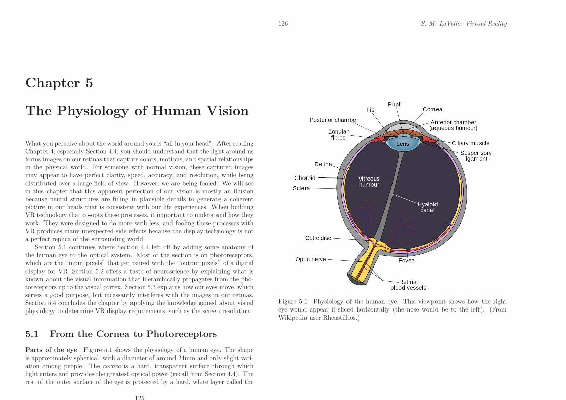
Parts of the eye Figure 5.1 shows the physiology of a human eye. The shapeis approximately spherical, with a diameter of around 24mm and only slight vari-ation among people. The cornea is a hard, transparent surface through whichlight enters and provides the greatest optical power (recall from Section 4.4). Therest of the outer surface of the eye is protected by a hard, white layer called the
125
126 S. M. LaValle: Virtual Reality
Figure 5.1: Physiology of the human eye. This viewpoint shows how the righteye would appear if sliced horizontally (the nose would be to the left). (FromWikipedia user Rhcastilhos.)
5.1. FROM THE CORNEA TO PHOTORECEPTORS 127
sclera. Most of the eye interior consists of vitreous humor, which is a transpar-ent, gelatinous mass that allows light rays to penetrate with little distortion orattenuation.
As light rays cross the cornea, they pass through a small chamber containingaqueous humour, which is another transparent, gelatinous mass. After crossingthis, rays enter the lens by passing through the pupil. The size of the pupil iscontrolled by a disc-shaped structure called the iris, which provides an aperturethat regulates the amount of light that is allowed to pass. The optical power ofthe lens is altered by ciliary muscles. After passing through the lens, rays passthrough the vitreous humor and strike the retina, which lines more than 180◦ ofthe inner eye boundary. Since Figure 5.1 shows a 2D cross section, the retinais shaped like an arc; however, keep in mind that it is a 2D surface. Imagine itas a curved counterpart to a visual display. To catch the light from the outputpixels, it is lined with photoreceptors, which behave like “input pixels”. The mostimportant part of the retina is the fovea; the highest visual acuity, which is ameasure of the sharpness or clarity of vision, is provided for rays that land onit. The optic disc is a small hole in the retina through which neural pulses aretransmitted outside of the eye through the optic nerve. It is on the same side ofthe fovea as the nose.
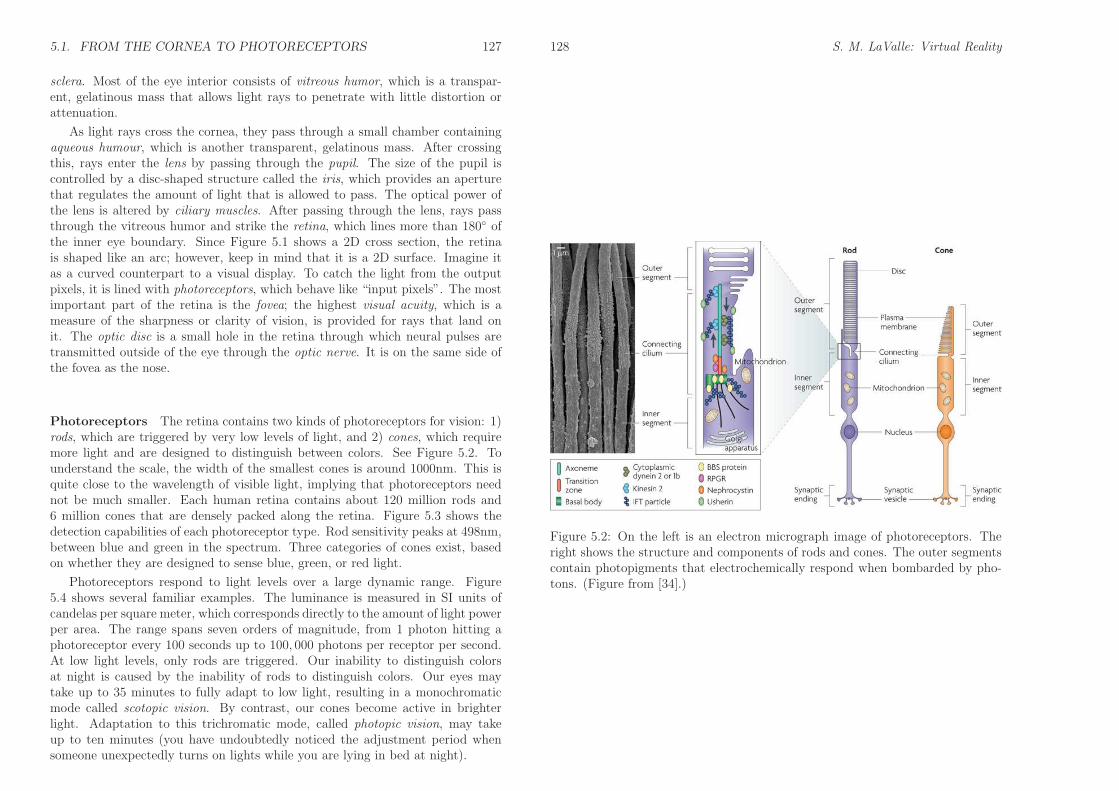
Photoreceptors The retina contains two kinds of photoreceptors for vision: 1)rods, which are triggered by very low levels of light, and 2) cones, which requiremore light and are designed to distinguish between colors. See Figure 5.2. Tounderstand the scale, the width of the smallest cones is around 1000nm. This isquite close to the wavelength of visible light, implying that photoreceptors neednot be much smaller. Each human retina contains about 120 million rods and6 million cones that are densely packed along the retina. Figure 5.3 shows thedetection capabilities of each photoreceptor type. Rod sensitivity peaks at 498nm,between blue and green in the spectrum. Three categories of cones exist, basedon whether they are designed to sense blue, green, or red light.
Photoreceptors respond to light levels over a large dynamic range. Figure5.4 shows several familiar examples. The luminance is measured in SI units ofcandelas per square meter, which corresponds directly to the amount of light powerper area. The range spans seven orders of magnitude, from 1 photon hitting aphotoreceptor every 100 seconds up to 100, 000 photons per receptor per second.At low light levels, only rods are triggered. Our inability to distinguish colorsat night is caused by the inability of rods to distinguish colors. Our eyes maytake up to 35 minutes to fully adapt to low light, resulting in a monochromaticmode called scotopic vision. By contrast, our cones become active in brighterlight. Adaptation to this trichromatic mode, called photopic vision, may takeup to ten minutes (you have undoubtedly noticed the adjustment period whensomeone unexpectedly turns on lights while you are lying in bed at night).
128 S. M. LaValle: Virtual Reality
Figure 5.2: On the left is an electron micrograph image of photoreceptors. Theright shows the structure and components of rods and cones. The outer segmentscontain photopigments that electrochemically respond when bombarded by pho-tons. (Figure from [34].)
5.1. FROM THE CORNEA TO PHOTORECEPTORS 129
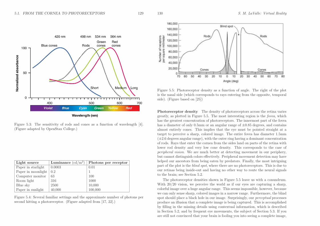
Figure 5.3: The sensitivity of rods and cones as a function of wavelength [4].(Figure adapted by OpenStax College.)
Light source Luminance (cd/m2) Photons per receptorPaper in starlight 0.0003 0.01Paper in moonlight 0.2 1Computer monitor 63 100Room light 316 1000Blue sky 2500 10,000Paper in sunlight 40,000 100,000
Figure 5.4: Several familiar settings and the approximate number of photons persecond hitting a photoreceptor. (Figure adapted from [17, 22].)
130 S. M. LaValle: Virtual Reality
Figure 5.5: Photoreceptor density as a function of angle. The right of the plotis the nasal side (which corresponds to rays entering from the opposite, temporalside). (Figure based on [25])
Photoreceptor density The density of photoreceptors across the retina variesgreatly, as plotted in Figure 5.5. The most interesting region is the fovea, whichhas the greatest concentration of photoreceptors. The innermost part of the foveahas a diameter of only 0.5mm or an angular range of ±0.85 degrees, and containsalmost entirely cones. This implies that the eye must be pointed straight at atarget to perceive a sharp, colored image. The entire fovea has diameter 1.5mm(±2.6 degrees angular range), with the outer ring having a dominant concentrationof rods. Rays that enter the cornea from the sides land on parts of the retina withlower rod density and very low cone density. This corresponds to the case ofperipheral vision. We are much better at detecting movement in our periphery,but cannot distinguish colors effectively. Peripheral movement detection may havehelped our ancestors from being eaten by predators. Finally, the most intriguingpart of the plot is the blind spot, where there are no photoreceptors. This is due toour retinas being inside-out and having no other way to route the neural signalsto the brain; see Section 5.2.
The photoreceptor densities shown in Figure 5.5 leave us with a conundrum.With 20/20 vision, we perceive the world as if our eyes are capturing a sharp,colorful image over a huge angular range. This seems impossible, however, becausewe can only sense sharp, colored images in a narrow range. Furthermore, the blindspot should place a black hole in our image. Surprisingly, our perceptual processesproduce an illusion that a complete image is being captured. This is accomplishedby filling in the missing details using contextual information, which is describedin Section 5.2, and by frequent eye movements, the subject of Section 5.3. If youare still not convinced that your brain is fooling you into seeing a complete image,
5.2. FROM PHOTORECEPTORS TO THE VISUAL CORTEX 131
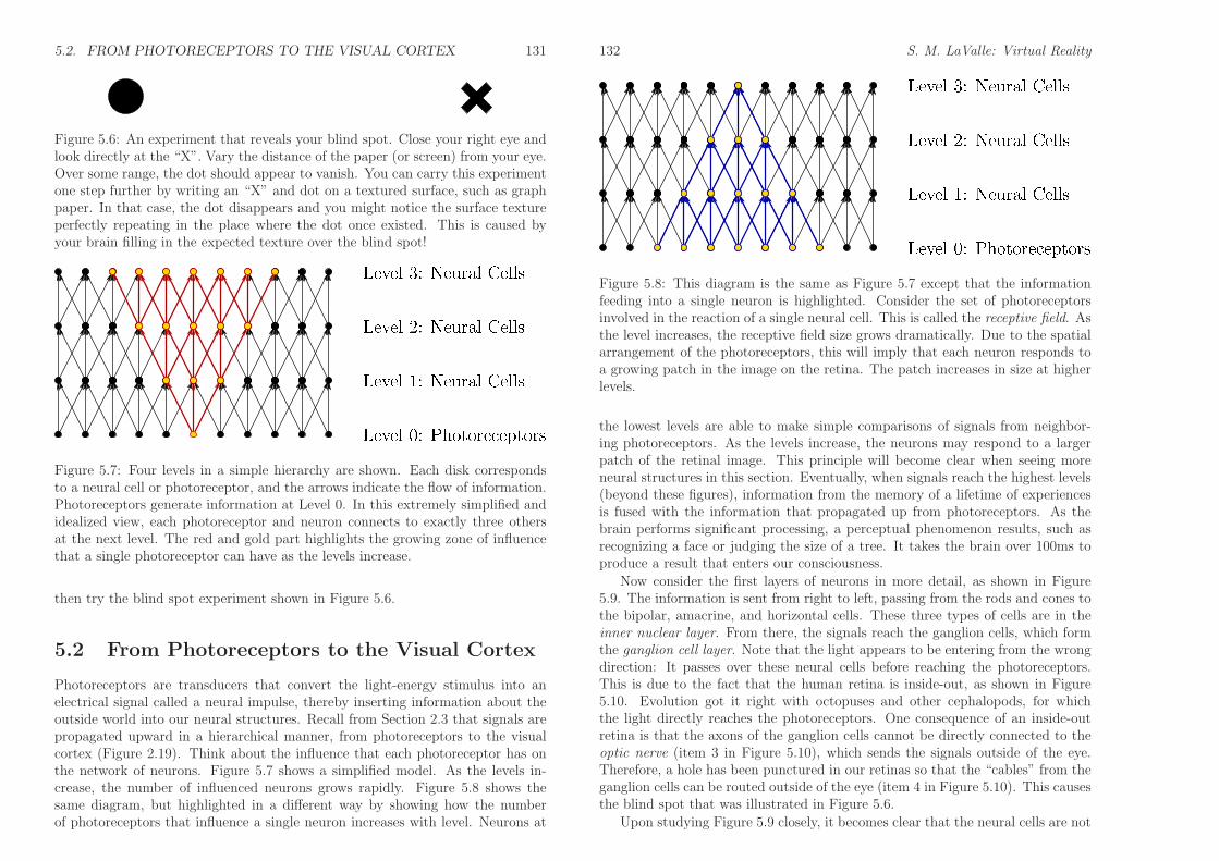
Figure 5.6: An experiment that reveals your blind spot. Close your right eye andlook directly at the “X”. Vary the distance of the paper (or screen) from your eye.Over some range, the dot should appear to vanish. You can carry this experimentone step further by writing an “X” and dot on a textured surface, such as graphpaper. In that case, the dot disappears and you might notice the surface textureperfectly repeating in the place where the dot once existed. This is caused byyour brain filling in the expected texture over the blind spot!
Figure 5.7: Four levels in a simple hierarchy are shown. Each disk correspondsto a neural cell or photoreceptor, and the arrows indicate the flow of information.Photoreceptors generate information at Level 0. In this extremely simplified andidealized view, each photoreceptor and neuron connects to exactly three othersat the next level. The red and gold part highlights the growing zone of influencethat a single photoreceptor can have as the levels increase.
then try the blind spot experiment shown in Figure 5.6.
5.2 From Photoreceptors to the Visual Cortex
Photoreceptors are transducers that convert the light-energy stimulus into anelectrical signal called a neural impulse, thereby inserting information about theoutside world into our neural structures. Recall from Section 2.3 that signals arepropagated upward in a hierarchical manner, from photoreceptors to the visualcortex (Figure 2.19). Think about the influence that each photoreceptor has onthe network of neurons. Figure 5.7 shows a simplified model. As the levels in-crease, the number of influenced neurons grows rapidly. Figure 5.8 shows thesame diagram, but highlighted in a different way by showing how the numberof photoreceptors that influence a single neuron increases with level. Neurons at
132 S. M. LaValle: Virtual Reality
Figure 5.8: This diagram is the same as Figure 5.7 except that the informationfeeding into a single neuron is highlighted. Consider the set of photoreceptorsinvolved in the reaction of a single neural cell. This is called the receptive field. Asthe level increases, the receptive field size grows dramatically. Due to the spatialarrangement of the photoreceptors, this will imply that each neuron responds toa growing patch in the image on the retina. The patch increases in size at higherlevels.
the lowest levels are able to make simple comparisons of signals from neighbor-ing photoreceptors. As the levels increase, the neurons may respond to a largerpatch of the retinal image. This principle will become clear when seeing moreneural structures in this section. Eventually, when signals reach the highest levels(beyond these figures), information from the memory of a lifetime of experiencesis fused with the information that propagated up from photoreceptors. As thebrain performs significant processing, a perceptual phenomenon results, such asrecognizing a face or judging the size of a tree. It takes the brain over 100ms toproduce a result that enters our consciousness.
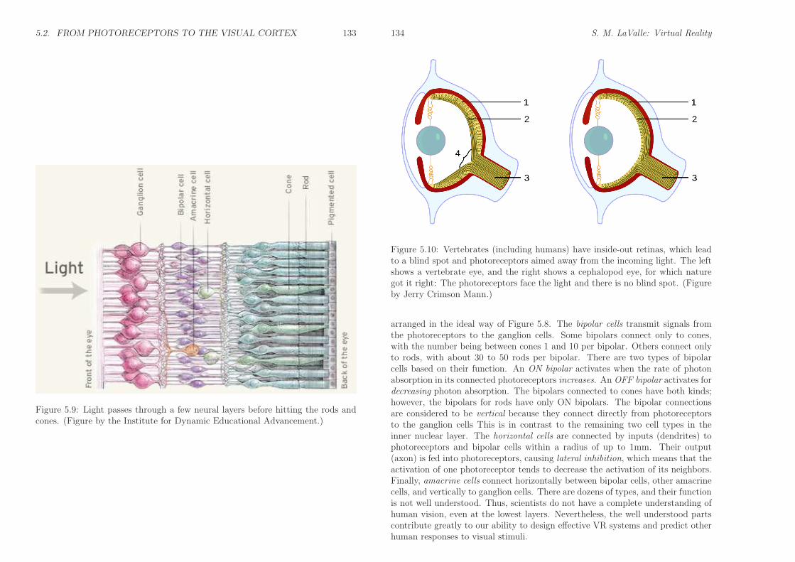
Now consider the first layers of neurons in more detail, as shown in Figure5.9. The information is sent from right to left, passing from the rods and cones tothe bipolar, amacrine, and horizontal cells. These three types of cells are in theinner nuclear layer. From there, the signals reach the ganglion cells, which formthe ganglion cell layer. Note that the light appears to be entering from the wrongdirection: It passes over these neural cells before reaching the photoreceptors.This is due to the fact that the human retina is inside-out, as shown in Figure5.10. Evolution got it right with octopuses and other cephalopods, for whichthe light directly reaches the photoreceptors. One consequence of an inside-outretina is that the axons of the ganglion cells cannot be directly connected to theoptic nerve (item 3 in Figure 5.10), which sends the signals outside of the eye.Therefore, a hole has been punctured in our retinas so that the “cables” from theganglion cells can be routed outside of the eye (item 4 in Figure 5.10). This causesthe blind spot that was illustrated in Figure 5.6.
Upon studying Figure 5.9 closely, it becomes clear that the neural cells are not
5.2. FROM PHOTORECEPTORS TO THE VISUAL CORTEX 133
Figure 5.9: Light passes through a few neural layers before hitting the rods andcones. (Figure by the Institute for Dynamic Educational Advancement.)
134 S. M. LaValle: Virtual Reality
Figure 5.10: Vertebrates (including humans) have inside-out retinas, which leadto a blind spot and photoreceptors aimed away from the incoming light. The leftshows a vertebrate eye, and the right shows a cephalopod eye, for which naturegot it right: The photoreceptors face the light and there is no blind spot. (Figureby Jerry Crimson Mann.)
arranged in the ideal way of Figure 5.8. The bipolar cells transmit signals fromthe photoreceptors to the ganglion cells. Some bipolars connect only to cones,with the number being between cones 1 and 10 per bipolar. Others connect onlyto rods, with about 30 to 50 rods per bipolar. There are two types of bipolarcells based on their function. An ON bipolar activates when the rate of photonabsorption in its connected photoreceptors increases. An OFF bipolar activates fordecreasing photon absorption. The bipolars connected to cones have both kinds;however, the bipolars for rods have only ON bipolars. The bipolar connectionsare considered to be vertical because they connect directly from photoreceptorsto the ganglion cells This is in contrast to the remaining two cell types in theinner nuclear layer. The horizontal cells are connected by inputs (dendrites) tophotoreceptors and bipolar cells within a radius of up to 1mm. Their output(axon) is fed into photoreceptors, causing lateral inhibition, which means that theactivation of one photoreceptor tends to decrease the activation of its neighbors.Finally, amacrine cells connect horizontally between bipolar cells, other amacrinecells, and vertically to ganglion cells. There are dozens of types, and their functionis not well understood. Thus, scientists do not have a complete understanding ofhuman vision, even at the lowest layers. Nevertheless, the well understood partscontribute greatly to our ability to design effective VR systems and predict otherhuman responses to visual stimuli.
5.2. FROM PHOTORECEPTORS TO THE VISUAL CORTEX 135
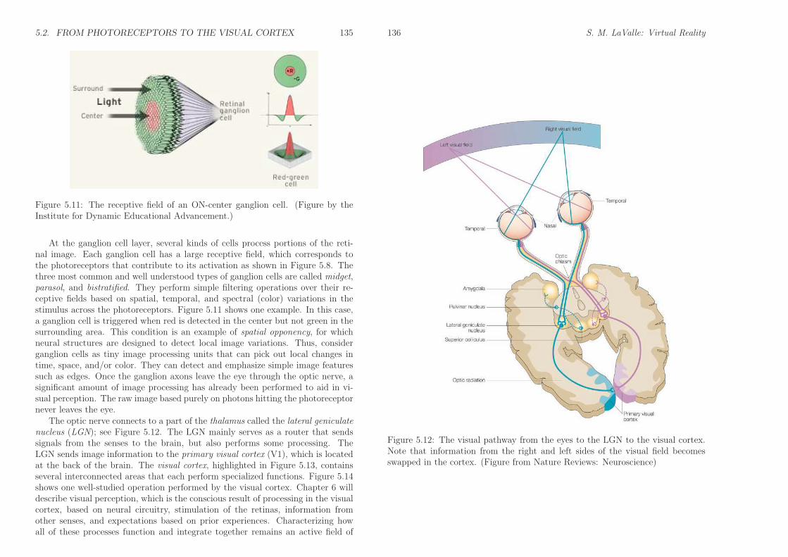
Figure 5.11: The receptive field of an ON-center ganglion cell. (Figure by theInstitute for Dynamic Educational Advancement.)
At the ganglion cell layer, several kinds of cells process portions of the reti-nal image. Each ganglion cell has a large receptive field, which corresponds tothe photoreceptors that contribute to its activation as shown in Figure 5.8. Thethree most common and well understood types of ganglion cells are called midget,parasol, and bistratified. They perform simple filtering operations over their re-ceptive fields based on spatial, temporal, and spectral (color) variations in thestimulus across the photoreceptors. Figure 5.11 shows one example. In this case,a ganglion cell is triggered when red is detected in the center but not green in thesurrounding area. This condition is an example of spatial opponency, for whichneural structures are designed to detect local image variations. Thus, considerganglion cells as tiny image processing units that can pick out local changes intime, space, and/or color. They can detect and emphasize simple image featuressuch as edges. Once the ganglion axons leave the eye through the optic nerve, asignificant amount of image processing has already been performed to aid in vi-sual perception. The raw image based purely on photons hitting the photoreceptornever leaves the eye.
The optic nerve connects to a part of the thalamus called the lateral geniculatenucleus (LGN); see Figure 5.12. The LGN mainly serves as a router that sendssignals from the senses to the brain, but also performs some processing. TheLGN sends image information to the primary visual cortex (V1), which is locatedat the back of the brain. The visual cortex, highlighted in Figure 5.13, containsseveral interconnected areas that each perform specialized functions. Figure 5.14shows one well-studied operation performed by the visual cortex. Chapter 6 willdescribe visual perception, which is the conscious result of processing in the visualcortex, based on neural circuitry, stimulation of the retinas, information fromother senses, and expectations based on prior experiences. Characterizing howall of these processes function and integrate together remains an active field of
136 S. M. LaValle: Virtual Reality
Figure 5.12: The visual pathway from the eyes to the LGN to the visual cortex.Note that information from the right and left sides of the visual field becomesswapped in the cortex. (Figure from Nature Reviews: Neuroscience)
5.3. EYE MOVEMENTS 137
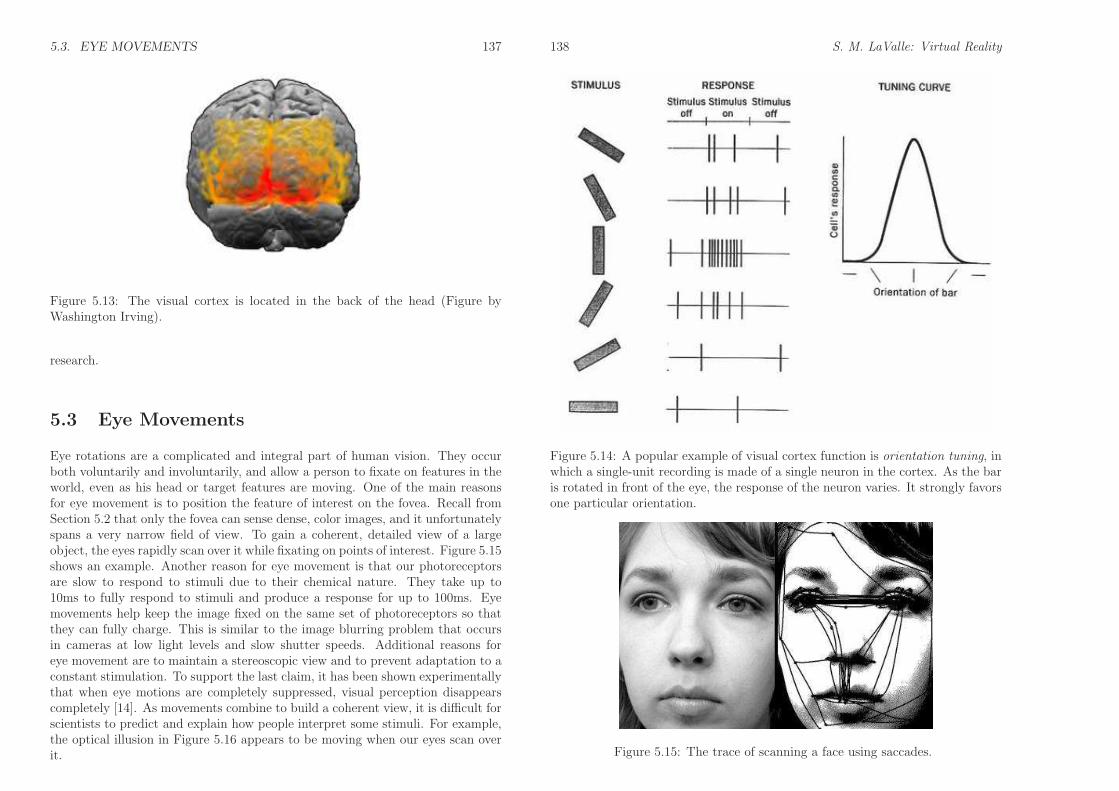
Figure 5.13: The visual cortex is located in the back of the head (Figure byWashington Irving).
research.
5.3 Eye Movements
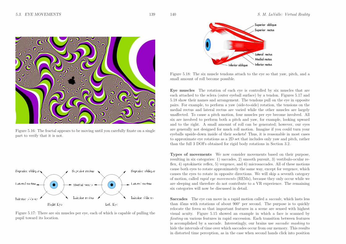
Eye rotations are a complicated and integral part of human vision. They occurboth voluntarily and involuntarily, and allow a person to fixate on features in theworld, even as his head or target features are moving. One of the main reasonsfor eye movement is to position the feature of interest on the fovea. Recall fromSection 5.2 that only the fovea can sense dense, color images, and it unfortunatelyspans a very narrow field of view. To gain a coherent, detailed view of a largeobject, the eyes rapidly scan over it while fixating on points of interest. Figure 5.15shows an example. Another reason for eye movement is that our photoreceptorsare slow to respond to stimuli due to their chemical nature. They take up to10ms to fully respond to stimuli and produce a response for up to 100ms. Eyemovements help keep the image fixed on the same set of photoreceptors so thatthey can fully charge. This is similar to the image blurring problem that occursin cameras at low light levels and slow shutter speeds. Additional reasons foreye movement are to maintain a stereoscopic view and to prevent adaptation to aconstant stimulation. To support the last claim, it has been shown experimentallythat when eye motions are completely suppressed, visual perception disappearscompletely [14]. As movements combine to build a coherent view, it is difficult forscientists to predict and explain how people interpret some stimuli. For example,the optical illusion in Figure 5.16 appears to be moving when our eyes scan overit.
138 S. M. LaValle: Virtual Reality
Figure 5.14: A popular example of visual cortex function is orientation tuning, inwhich a single-unit recording is made of a single neuron in the cortex. As the baris rotated in front of the eye, the response of the neuron varies. It strongly favorsone particular orientation.
Figure 5.15: The trace of scanning a face using saccades.
5.3. EYE MOVEMENTS 139
Figure 5.16: The fractal appears to be moving until you carefully fixate on a singlepart to verify that it is not.
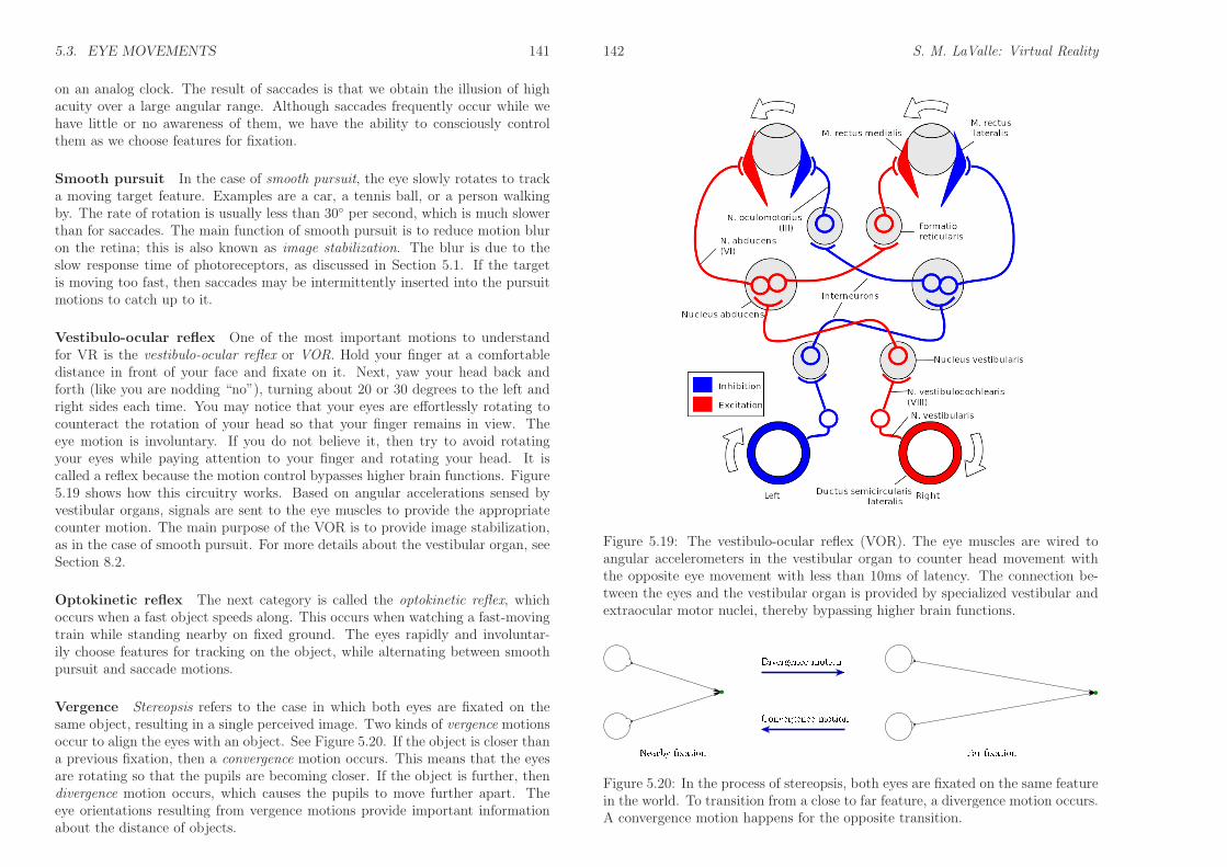
Figure 5.17: There are six muscles per eye, each of which is capable of pulling thepupil toward its location.
140 S. M. LaValle: Virtual Reality
Figure 5.18: The six muscle tendons attach to the eye so that yaw, pitch, and asmall amount of roll become possible.
Eye muscles The rotation of each eye is controlled by six muscles that areeach attached to the sclera (outer eyeball surface) by a tendon. Figures 5.17 and5.18 show their names and arrangement. The tendons pull on the eye in oppositepairs. For example, to perform a yaw (side-to-side) rotation, the tensions on themedial rectus and lateral rectus are varied while the other muscles are largelyunaffected. To cause a pitch motion, four muscles per eye become involved. Allsix are involved to perform both a pitch and yaw, for example, looking upwardand to the right. A small amount of roll can be generated; however, our eyesare generally not designed for much roll motion. Imagine if you could turn youreyeballs upside-down inside of their sockets! Thus, it is reasonable in most casesto approximate eye rotations as a 2D set that includes only yaw and pitch, ratherthan the full 3 DOFs obtained for rigid body rotations in Section 3.2.
Types of movements We now consider movements based on their purpose,resulting in six categories: 1) saccades, 2) smooth pursuit, 3) vestibulo-ocular re-flex, 4) optokinetic reflex, 5) vergence, and 6) microsaccades. All of these motionscause both eyes to rotate approximately the same way, except for vergence, whichcauses the eyes to rotate in opposite directions. We will skip a seventh categoryof motion, called rapid eye movements (REMs), because they only occur while weare sleeping and therefore do not contribute to a VR experience. The remainingsix categories will now be discussed in detail.
Saccades The eye can move in a rapid motion called a saccade, which lasts lessthan 45ms with rotations of about 900◦ per second. The purpose is to quicklyrelocate the fovea so that important features in a scene are sensed with highestvisual acuity. Figure 5.15 showed an example in which a face is scanned byfixating on various features in rapid succession. Each transition between featuresis accomplished by a saccade. Interestingly, our brains use saccadic masking tohide the intervals of time over which saccades occur from our memory. This resultsin distorted time perception, as in the case when second hands click into position
5.3. EYE MOVEMENTS 141
on an analog clock. The result of saccades is that we obtain the illusion of highacuity over a large angular range. Although saccades frequently occur while wehave little or no awareness of them, we have the ability to consciously controlthem as we choose features for fixation.
Smooth pursuit In the case of smooth pursuit, the eye slowly rotates to tracka moving target feature. Examples are a car, a tennis ball, or a person walkingby. The rate of rotation is usually less than 30◦ per second, which is much slowerthan for saccades. The main function of smooth pursuit is to reduce motion bluron the retina; this is also known as image stabilization. The blur is due to theslow response time of photoreceptors, as discussed in Section 5.1. If the targetis moving too fast, then saccades may be intermittently inserted into the pursuitmotions to catch up to it.
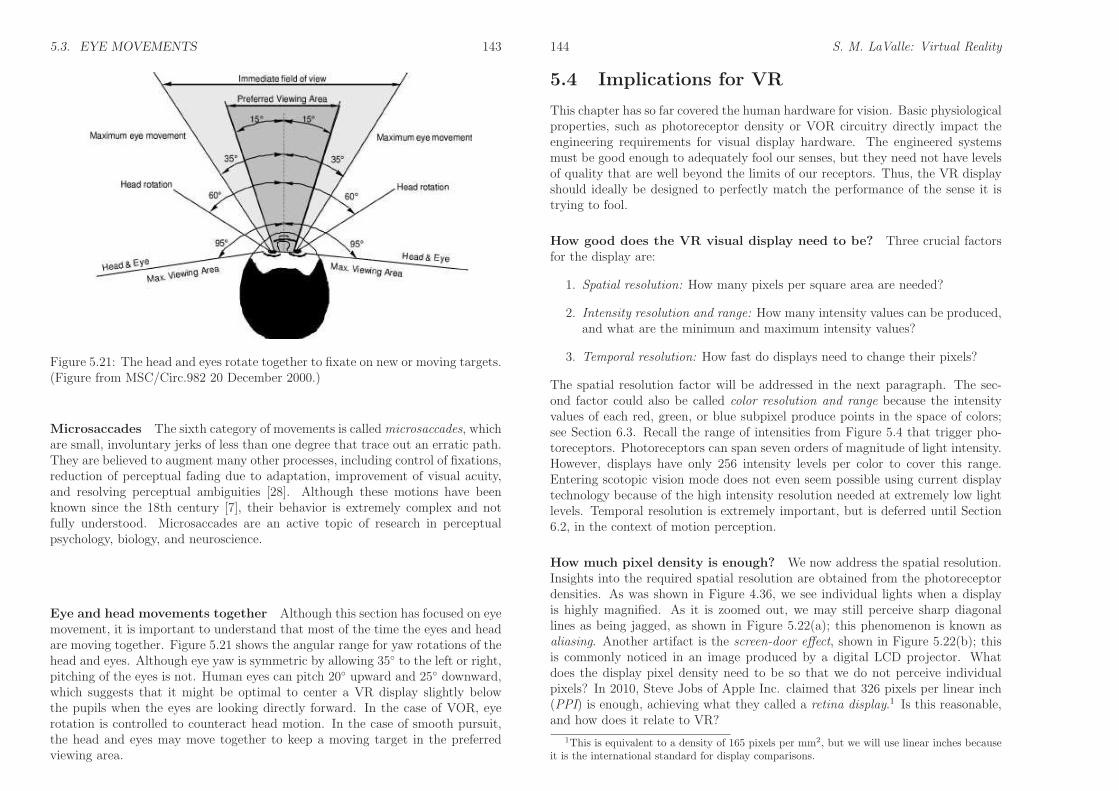
Vestibulo-ocular reflex One of the most important motions to understandfor VR is the vestibulo-ocular reflex or VOR. Hold your finger at a comfortabledistance in front of your face and fixate on it. Next, yaw your head back andforth (like you are nodding “no”), turning about 20 or 30 degrees to the left andright sides each time. You may notice that your eyes are effortlessly rotating tocounteract the rotation of your head so that your finger remains in view. Theeye motion is involuntary. If you do not believe it, then try to avoid rotatingyour eyes while paying attention to your finger and rotating your head. It iscalled a reflex because the motion control bypasses higher brain functions. Figure5.19 shows how this circuitry works. Based on angular accelerations sensed byvestibular organs, signals are sent to the eye muscles to provide the appropriatecounter motion. The main purpose of the VOR is to provide image stabilization,as in the case of smooth pursuit. For more details about the vestibular organ, seeSection 8.2.
Optokinetic reflex The next category is called the optokinetic reflex, whichoccurs when a fast object speeds along. This occurs when watching a fast-movingtrain while standing nearby on fixed ground. The eyes rapidly and involuntar-ily choose features for tracking on the object, while alternating between smoothpursuit and saccade motions.
Vergence Stereopsis refers to the case in which both eyes are fixated on thesame object, resulting in a single perceived image. Two kinds of vergence motionsoccur to align the eyes with an object. See Figure 5.20. If the object is closer thana previous fixation, then a convergence motion occurs. This means that the eyesare rotating so that the pupils are becoming closer. If the object is further, thendivergence motion occurs, which causes the pupils to move further apart. Theeye orientations resulting from vergence motions provide important informationabout the distance of objects.
142 S. M. LaValle: Virtual Reality
Figure 5.19: The vestibulo-ocular reflex (VOR). The eye muscles are wired toangular accelerometers in the vestibular organ to counter head movement withthe opposite eye movement with less than 10ms of latency. The connection be-tween the eyes and the vestibular organ is provided by specialized vestibular andextraocular motor nuclei, thereby bypassing higher brain functions.
Figure 5.20: In the process of stereopsis, both eyes are fixated on the same featurein the world. To transition from a close to far feature, a divergence motion occurs.A convergence motion happens for the opposite transition.
5.3. EYE MOVEMENTS 143
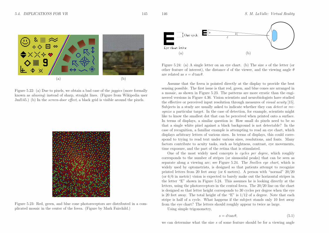
Figure 5.21: The head and eyes rotate together to fixate on new or moving targets.(Figure from MSC/Circ.982 20 December 2000.)
Microsaccades The sixth category of movements is calledmicrosaccades, whichare small, involuntary jerks of less than one degree that trace out an erratic path.They are believed to augment many other processes, including control of fixations,reduction of perceptual fading due to adaptation, improvement of visual acuity,and resolving perceptual ambiguities [28]. Although these motions have beenknown since the 18th century [7], their behavior is extremely complex and notfully understood. Microsaccades are an active topic of research in perceptualpsychology, biology, and neuroscience.
Eye and head movements together Although this section has focused on eyemovement, it is important to understand that most of the time the eyes and headare moving together. Figure 5.21 shows the angular range for yaw rotations of thehead and eyes. Although eye yaw is symmetric by allowing 35◦ to the left or right,pitching of the eyes is not. Human eyes can pitch 20◦ upward and 25◦ downward,which suggests that it might be optimal to center a VR display slightly belowthe pupils when the eyes are looking directly forward. In the case of VOR, eyerotation is controlled to counteract head motion. In the case of smooth pursuit,the head and eyes may move together to keep a moving target in the preferredviewing area.
144 S. M. LaValle: Virtual Reality
5.4 Implications for VR
This chapter has so far covered the human hardware for vision. Basic physiologicalproperties, such as photoreceptor density or VOR circuitry directly impact theengineering requirements for visual display hardware. The engineered systemsmust be good enough to adequately fool our senses, but they need not have levelsof quality that are well beyond the limits of our receptors. Thus, the VR displayshould ideally be designed to perfectly match the performance of the sense it istrying to fool.
How good does the VR visual display need to be? Three crucial factorsfor the display are:
1. Spatial resolution: How many pixels per square area are needed?
2. Intensity resolution and range: How many intensity values can be produced,and what are the minimum and maximum intensity values?
3. Temporal resolution: How fast do displays need to change their pixels?
The spatial resolution factor will be addressed in the next paragraph. The sec-ond factor could also be called color resolution and range because the intensityvalues of each red, green, or blue subpixel produce points in the space of colors;see Section 6.3. Recall the range of intensities from Figure 5.4 that trigger pho-toreceptors. Photoreceptors can span seven orders of magnitude of light intensity.However, displays have only 256 intensity levels per color to cover this range.Entering scotopic vision mode does not even seem possible using current displaytechnology because of the high intensity resolution needed at extremely low lightlevels. Temporal resolution is extremely important, but is deferred until Section6.2, in the context of motion perception.
How much pixel density is enough? We now address the spatial resolution.Insights into the required spatial resolution are obtained from the photoreceptordensities. As was shown in Figure 4.36, we see individual lights when a displayis highly magnified. As it is zoomed out, we may still perceive sharp diagonallines as being jagged, as shown in Figure 5.22(a); this phenomenon is known asaliasing. Another artifact is the screen-door effect, shown in Figure 5.22(b); thisis commonly noticed in an image produced by a digital LCD projector. Whatdoes the display pixel density need to be so that we do not perceive individualpixels? In 2010, Steve Jobs of Apple Inc. claimed that 326 pixels per linear inch(PPI) is enough, achieving what they called a retina display.1 Is this reasonable,and how does it relate to VR?
1This is equivalent to a density of 165 pixels per mm2, but we will use linear inches becauseit is the international standard for display comparisons.
5.4. IMPLICATIONS FOR VR 145
(a) (b)
Figure 5.22: (a) Due to pixels, we obtain a bad case of the jaggies (more formallyknown as aliasing) instead of sharp, straight lines. (Figure from Wikipedia userJmf145.) (b) In the screen-door effect, a black grid is visible around the pixels.
Figure 5.23: Red, green, and blue cone photoreceptors are distributed in a com-plicated mosaic in the center of the fovea. (Figure by Mark Fairchild.)
146 S. M. LaValle: Virtual Reality
(a) (b)
Figure 5.24: (a) A single letter on an eye chart. (b) The size s of the letter (orother feature of interest), the distance d of the viewer, and the viewing angle θare related as s = d tan θ.
Assume that the fovea is pointed directly at the display to provide the bestsensing possible. The first issue is that red, green, and blue cones are arranged ina mosaic, as shown in Figure 5.23. The patterns are more erratic than the engi-neered versions in Figure 4.36. Vision scientists and neurobiologists have studiedthe effective or perceived input resolution through measures of visual acuity [15].Subjects in a study are usually asked to indicate whether they can detect or rec-ognize a particular target. In the case of detection, for example, scientists mightlike to know the smallest dot that can be perceived when printed onto a surface.In terms of displays, a similar question is: How small do pixels need to be sothat a single white pixel against a black background is not detectable? In thecase of recognition, a familiar example is attempting to read an eye chart, whichdisplays arbitrary letters of various sizes. In terms of displays, this could corre-spond to trying to read text under various sizes, resolutions, and fonts. Manyfactors contribute to acuity tasks, such as brightness, contrast, eye movements,time exposure, and the part of the retina that is stimulated.
One of the most widely used concepts is cycles per degree, which roughlycorresponds to the number of stripes (or sinusoidal peaks) that can be seen asseparate along a viewing arc; see Figure 5.24. The Snellen eye chart, which iswidely used by optometrists, is designed so that patients attempt to recognizeprinted letters from 20 feet away (or 6 meters). A person with “normal” 20/20(or 6/6 in metric) vision is expected to barely make out the horizontal stripes inthe letter “E” shown in Figure 5.24. This assumes he is looking directly at theletters, using the photoreceptors in the central fovea. The 20/20 line on the chartis designed so that letter height corresponds to 30 cycles per degree when the eyeis 20 feet away. The total height of the “E” is 1/12 of a degree. Note that eachstripe is half of a cycle. What happens if the subject stands only 10 feet awayfrom the eye chart? The letters should roughly appear to twice as large.
Using simple trigonometry,
s = d tan θ, (5.1)
we can determine what the size s of some feature should be for a viewing angle
5.4. IMPLICATIONS FOR VR 147
θ at a distance d from the eye. For very small θ, tan θ ≈ θ (in radians). For theexample of the eye chart, s could correspond to the height of a letter. Doublingthe distance d and the size s should keep θ roughly fixed, which corresponds tothe size of the image on the retina.
We now return to the retina display concept. Suppose that a person with20/20 vision is viewing a large screen that is 20 feet (6.096m) away. To generate30 cycles per degree, it must have at least 60 pixels per degree. Using (5.1), thesize would be s = 20 ∗ tan 1◦ = 0.349ft, which is equivalent to 4.189in. Thus, only60/4.189 = 14.32 PPI would be sufficient. Now suppose that a smartphone screenis placed 12 inches from the user’s eye. In this case, s = 12∗tan 1◦ = 0.209in. Thisrequires that the screen have at least 60/0.209 = 286.4 PPI, which was satisfiedby the 326 PPI originally claimed by Apple.
In the case of VR, the user is not looking directly at the screen as in the caseof smartphones. By inserting a lens for magnification, the display can be broughteven closer to the eye. This is commonly done for VR headsets, as was shown inFigure 4.30. Suppose that the lens is positioned at its focal distance away from thescreen, which for the sake of example is only 1.5in (this is comparable to currentVR headsets). In this case, s = 1 ∗ tan 1◦ = 0.0261in, and the display must haveat least 2291.6 PPI to achieve 60 cycles per degree! One of the highest-densitysmartphone displays available today is in the Sony Xperia Z5 Premium. It hasonly 801 PPI, which means that the PPI needs to increase by roughly a factor ofthree to obtain retina display resolution for VR headsets.
This is not the complete story because some people, particularly youths, havebetter than 20/20 vision. The limits of visual acuity have been established tobe around 60 to 77 cycles per degree, based on photoreceptor density and neuralprocesses [5, 6]; however, this is based on shining a laser directly onto the retina,which bypasses many optical aberration problems as the light passes through theeye. A small number of people (perhaps one percent) have acuity up to 60 cyclesper degree. In this extreme case, the display density would need to be 4583 PPI.Thus, many factors are involved in determining a sufficient resolution for VR. Itsuffices to say that the resolutions that exist today in consumer VR headsets areinadequate, and retinal display resolution will not be achieved until the PPI isseveral times higher.
How much field of view is enough? What if the screen is brought even closerto the eye to fill more of the field of view? Based on the photoreceptor density plotin Figure 5.5 and the limits of eye rotations shown in Figure 5.21, the maximumfield of view seems to be around 270◦, which is larger than what could be providedby a flat screen (less than 180◦). Increasing the field of view by bringing the screencloser would require even higher pixel density, but lens aberrations (Section 4.3)at the periphery may limit the effective field of view. Furthermore, if the lensis too thick and too close to the eye, then the eyelashes may scrape it; Fresnellenses may provide a thin alternative, but introduce artifacts. Thus, the quest
148 S. M. LaValle: Virtual Reality
for a VR retina display may end with a balance between optical system qualityand limitations of the human eye. Curved screens may help alleviate some of theproblems.
Foveated rendering One of the frustrations with this analysis is that we havenot been able to exploit that fact that photoreceptor density decreases away fromthe fovea. We had to keep the pixel density high everywhere because we have nocontrol over which part of the display the user will be look at. If we could trackwhere the eye is looking and have a tiny, movable display that is always positionedin front of the pupil, with zero delay, then much fewer pixels would be needed. Thiswould greatly decrease computational burdens on graphical rendering systems(covered in Chapter 7). Instead of moving a tiny screen, the process can besimulated by keeping the fixed display but focusing the graphical rendering onlyin the spot where the eye is looking. This is called foveated rendering, which hasbeen shown to work [13], but is currently too costly and there is too much delayand other discrepancies between the eye movements and the display updates. Inthe near future, it may become an effective approach for the mass market.
VOR gain adaptation The VOR gain is a ratio that compares the eye rota-tion rate (numerator) to counter the rotation and translation rate of the head(denominator). Because head motion has six DOFs, it is appropriate to break thegain into six components. In the case of head pitch and yaw, the VOR gain isclose to 1.0. For example, if you yaw your head to the left at 10◦ per second, thenyour eyes yaw at 10◦ per second in the opposite direction. The VOR roll gain isvery small because the eyes have a tiny roll range. The VOR translational gaindepends on the distance to the features.
Recall from Section 2.3 that adaptation is a universal feature of our sensorysystems. VOR gain is no exception. For those who wear eyeglasses, the VOR gainmust adapt due to the optical transformations described in Section 4.2. Lensesaffect the field of view and perceived size and distance of objects. The VORcomfortably adapts to this problem by changing the gain. Now suppose thatyou are wearing a VR headset that may suffer from flaws such as an imperfectoptical system, tracking latency, and incorrectly rendered objects on the screen.In this case, adaptation may occur as the brain attempts to adapt its perceptionof stationarity to compensate for the flaws. In this case, your visual systemcould convince your brain that the headset is functioning correctly, and then yourperception of stationarity in the real world would become distorted until youreadapt. For example, after a flawed VR experience, you might yaw your headin the real world and have the sensation that truly stationary objects are slidingback and forth!2
2This frequently happened to the author while developing and testing the Oculus Rift.
5.4. IMPLICATIONS FOR VR 149
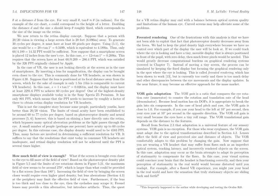
Figure 5.25: Most displays still work in the way as old TV sets and CRT monitors:By updating pixels line-by-line. For a display that has 60 FPS (frames per second),this could take up to 16.67ms.
Display scanout Recall from Section 4.5 that cameras have either a rolling orglobal shutter based on whether the sensing elements are scanned line-by-line orin parallel. Displays work the same way, but whereas cameras are an input device,displays are the output analog. Most displays today have a rolling scanout (calledraster scan), rather than global scanout. This implies that the pixels are updatedline by line, as shown in Figure 5.25. This procedure is an artifact of old TV setsand monitors, which each had a cathode ray tube (CRT) with phosphor elementson the screen. An electron beam was bent by electromagnets so that it wouldrepeatedly strike and refresh the glowing phosphors.
Due to the slow charge and response time of photoreceptors, we do not perceivethe scanout pattern during normal use. However, when our eyes, features in thescene, or both are moving, then side effects of the rolling scanout may becomeperceptible. Think about the operation of a line-by-line printer, as in the case ofa receipt printer on a cash register. If we pull on the tape while it is printing, thenthe lines would become stretched apart. If it is unable to print a single line atonce, then the lines themselves would become slanted. If we could pull the tape tothe side while it is printing, then the entire page would become slanted. You canalso achieve this effect by repeatedly drawing a horizontal line with a pencil whileusing the other hand to gently pull the paper in a particular direction. The paperin this analogy is the retina and the pencil corresponds to light rays attemptingto charge photoreceptors. Figure 5.26 shows how a rectangle would distort undercases of smooth pursuit and VOR. One possibility is to fix this by rendering adistorted image that will be corrected by the distortion due to the line-by-linescanout [23] (this was later suggested in [1]). Constructing these images requiresprecise calculations of the scanout timings. Yet another problem with displays isthat the pixels could take so long to switch (up to 20ms) that sharp edges appearto be blurred. We will continue discussing these problems in Section 6.2 in thecontext of motion perception, and Section 7.4 in the context of rendering.
150 S. M. LaValle: Virtual Reality
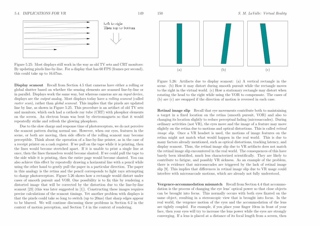
(a) (b) (c)
Figure 5.26: Artifacts due to display scanout: (a) A vertical rectangle in thescene. (b) How it may distort during smooth pursuit while the rectangle movesto the right in the virtual world. (c) How a stationary rectangle may distort whenrotating the head to the right while using the VOR to compensate. The cases of(b) are (c) are swapped if the direction of motion is reversed in each case.
Retinal image slip Recall that eye movements contribute both to maintaininga target in a fixed location on the retina (smooth pursuit, VOR) and also tochanging its location slightly to reduce perceptual fading (microsaccades). Duringordinary activities (not VR), the eyes move and the image of a feature may moveslightly on the retina due to motions and optical distortions. This is called retinal
image slip. Once a VR headset is used, the motions of image features on theretina might not match what would happen in the real world. This is due tomany factors already mentioned, such as optical distortions, tracking latency, anddisplay scanout. Thus, the retinal image slip due to VR artifacts does not matchthe retinal image slip encountered in the real world. The consequences of this havebarely been identified, much less characterized scientifically. They are likely tocontribute to fatigue, and possibly VR sickness. As an example of the problem,there is evidence that microsaccades are triggered by the lack of retinal imageslip [9]. This implies that differences in retinal image slip due to VR usage couldinterfere with microsaccade motions, which are already not fully understood.
Vergence-accommodation mismatch Recall from Section 4.4 that accommo-dation is the process of changing the eye lens’ optical power so that close objectscan be brought into focus. This normally occurs with both eyes fixated on thesame object, resulting in a stereoscopic view that is brought into focus. In thereal world, the vergence motion of the eyes and the accommodation of the lensare tightly coupled. For example, if you place your finger 10cm in front of yourface, then your eyes will try to increase the lens power while the eyes are stronglyconverging. If a lens is placed at a distance of its focal length from a screen, then
5.4. IMPLICATIONS FOR VR i
with normal eyes it will always be in focus while the eye is relaxed (recall Figure4.30). What if an object is rendered to the screen so that it appears to be only10cm away? In this case, the eyes strongly converge, but they do not need tochange the optical power of the eye lens. The eyes may nevertheless try to accom-modate, which would have the effect of blurring the perceived image. The resultis called vergence-accommodation mismatch because the stimulus provided by VRis inconsistent with the real world. Even if the eyes become accustomed to themismatch, the user may feel extra strain or fatigue after prolonged use [26, 30].The eyes are essentially being trained to allow a new degree of freedom: Sepa-rating vergence from accommodation, rather than coupling them. New displaytechnologies may provide some relief from this problem, but they are currentlytoo costly and imprecise. For example, the mismatch can be greatly reduced byusing eye tracking to estimate the amount of vergence and then altering the powerof the optical system [2, 21].
Further Reading
Most of the concepts from Sections 5.1 to 5.1 appear in standard textbooks on sensationand perception [12, 22, 33]. Chapter 7 of [22] contains substantially more neurosciencethan covered in this chapter. More details on photoreceptor structure appear in [6, 24,32]. The interface between eyes and engineered optical systems is covered in [31], ofwhich digital optical systems are also related [16].
Sweeping coverage of eye movements is provided in [20]. For eye movements froma neuroscience perspective, see [19]. VOR gain adaptation is studied in [8, 11, 29].Theories of microsaccade function are discussed in [28]. Coordination between smoothpursuit and saccades is explained in [10]. Coordination of head and eye movements isstudied in [18, 27]. See [3, 26, 30] regarding comfort issues with vergence-accommodationmismatch.
ii S. M. LaValle: Virtual Reality

Bibliography
[1] M. Abrash. Raster scan displays: More than meets the eye. Blog post.Retrieved from http://blogs.valvesoftware.com/abrash/raster-scan-displays-more-than-meets-the-eye/, January 2013. Last retrieved on Jan 10, 2016.
[2] K. Akeley, S. J. Watt, A. Reza Girschick, and M. S. Banks. A stereo displayprototype with multiple focal distances. ACM Transactions on Graphics,23(3), 2004.
[3] M. S. Banks, J. Kim, and T. Shibata. Insight into vergence-accommodationmismatch. In Proceedings of SPIE, 2013.
[4] J. K. Bowmaker and H. J. A. Dartnall. Visual pigment of rods and cones ina human retina. Journal of Physiology, 298:501–511, 1980.
[5] F. W. Campbell and D. G. Green. Optical and retinal factors affecting visualresolution. Journal of Physiology, 181:576–593, 1965.
[6] C. A. Curcio, K. R. Sloan, R. E. Kalina, and A. E. Hendrickson. Humanphotoreceptor topography. Journal of Comparative Neurobiology, 292:497–523, 1990.
[7] R. Darwin. New experiments on the ocular spectra of light and colours.Philosophical Transactions of the Royal Society of London, 76:313–348, 1786.
[8] J. L. Demer, J. Goldberg, H. A. Jenkins, and F. I. Porter. Vestibulo-ocularreflex during magnified vision: Adaptation to reduce visual-vestibular con-flict. Aviation, Space, and Environmental Medicine, 58(9 Pt 2):A175–A179,1987.
[9] R. Engbert and K. Mergenthaler. Mircosaccades are triggered by low retinalimage slip. Proceedings of the National Academy of Sciences of the United
States of America, 103(18):7192–7197, 2008.
[10] C. J. Erkelens. Coordination of smooth pursuit and saccades. Vision Re-
search, 46(1–2):163–170, 2006.
[11] G. M. Gauthier and D. A. Robinson. Adaptation of the human vestibulooc-ular reflex to magnifying lenses. Brain Research, 92(2):331–335, 1975.
iii
iv BIBLIOGRAPHY
[12] E. B. Goldstein. Sensation and Perception, 9th Ed. Wadsworth, Belmont,CA, 2014.
[13] B. Guentner, M. Finch, S. Drucker, D. Tan, and J. Snyder. Foveated3D graphics. Technical report, Microsoft Research, 2012. Available athttp://research.microsoft.com/.
[14] E. G. Heckenmueller. Stabilization of the retinal image: A review of method,effects, and theory. Psychological Bulletin, 63:157–169, 1965.
[15] M. Kalloniatis and C. Luu. Visual acuity. In H. Kolb, R. Nelson, E. Fernan-dez, and B. Jones, editors, Webvision: The Organization of the Retina and
Visual System. 2007. Last retrieved on October 18, 2016.
[16] B. C. Kress and P. Meyrueis. Applied Digital Optics: From Micro-optics to
Nanophotonics. Wiley, Hoboken, NJ, 2009.
[17] M. F. Land and S.-E. Nilsson. Animal Eyes. Oxford University Press, Oxford,UK, 2002.
[18] J. Lanman, E. Bizzi, and J. Allum. The coordination of eye and head move-ment during smooth pursuit. Brain Research, 153(1):39–53, 1978.
[19] R. J. Leigh and D. S. Zee. The Neurology of Eye Movements, 5th Ed. OxfordUniversity Press, 2015.
[20] S. Liversedge, I. Gilchrist, and S. Everling (eds). Oxford Handbook of Eye
Movements. Oxford University Press, 2011.
[21] G. D. Love, D. M. Hoffman, P. J. H. Hands, J. Gao, A. K. Kirby, and M. S.Banks. High-speed switchable lens enables the development of a volumetricstereoscopic display. Optics Express, 17(18):15716–15725, 2009.
[22] G. Mather. Foundations of Sensation and Perception. Psychology Press,Hove, UK, 2008.
[23] M. Mine and G. Bishop. Just-in-time pixels. Technical Report TR93-005,University of North Carolina, Chapel Hill, NC, 1993.
[24] D. Mustafi, A. H. Engel, and Palczewski. Structure of cone photoreceptors.Progress in Retinal and Eye Research, 28:289–302, 2009.
[25] G. Osterberg. Topography of the layer of rods and cones in the human retina.Acta Ophthalmologica, Supplement, 6:1–103, 1935.
[26] E. Peli. Optometric and perceptual issues with head-mounted displays. InP. Mouroulis, editor, Visual instrumentation : optical design and engineering
principles. McGraw-Hill, New York, NY, 1999.

BIBLIOGRAPHY v
[27] J. Pelz, M. Hayhoe, and R. Loeber. The coordination of eye, head, and handmovements in a natural task. Experimental Brain Research, 139(3):266–277,2001.
[28] M. Rolfs. Microsaccades: Small steps on a long way. Psychological Bulletin,49(20):2415–2441, 2009.
[29] M. Shelhamer, D. A. Robinson, and H. S. Tan. Context-specific adaptationof the gain of the vestibulo-ocular reflex in humans. Journal of Vestibular
Research: Equilibrium and Orientation, 2(1):89–96, 1992.
[30] T. Shibata, J. Kim, D. M. Hoffman, and M. S. Banks. The zone of comfort:predicting visual discomfort with stereo displays. Journal of Vision, 11(8):1–29, 2011.
[31] G. Smith and D. A. Atchison. The Eye and Visual Optical Instruments.Cambridge University Press, Cambridge, U.K., 1997.
[32] B. A. Wandell. Foundations of Vision. Sinauer Associates, 1995. Availableat https://foundationsofvision.stanford.edu/.
[33] J. M. Wolfe, K. R. Kluender, and D. M. Levi. Sensation and Perception, 4th
Ed. Sinauer, Sunderland, MA, 2015.
[34] A. F. Wright, C. F. Chakarova, M. M. Abd El-Aziz, and S. S. Bhattacharya.Photoreceptor degeneration: genetic and mechanistic dissection of a complextrait. Nature Reviews Genetics, 11:273–284, 2010.