Embed Size (px)
Citation preview
CANDU OverviewDr. George Bereznai
CHAPTER 5
Chapter 5: Steam, Turbine and Feedwaterpage 5 - J
STEAM, TURBINE AND FEEDWATER
CHAPTER OBJECTIVES:
At the end of this chapter, you will be able to describe the following featuresof the steam, turbine and feedwater systems used in CANDU generatingstations:
1. How steam ie produced, transfered to the turbine, condensed, and returnedto the boilers;
2. The reasons for the main design and operating features of the Turbine;3. The process of optimizing the thennodynamics of the steam and feedwater
cycle;4. The use of three element control to minimize fluctuations of steam
generator level;5. The use ofstandby equipment to ensure that the boliers are maintain their
role as heat sinks;6. The steam. flows during 'Poison Prevent' Operation, regulation of stearn
generator pressure and protection against overpressure.
The steam and feedwater system perfonns the following funl.1:ions:
a)
b)
c)
d)
e)
t)
g)
h)
- i)
Provides the means for the transfer ofheat energy from the primary heat transport system,and for the production ofsteam.
Conveys the stearn produced in the stearn generators to the high pressure turbine and otherbalance of plant loads.
Provides for overpressure protection ofthe steam generator secondary side.
Provides instrumentation for steam generator level and pressure control.
Provides for a crash cool ofthe steam generators on a loss-of-coola.'l.t.
Enables testing of one turbine stop valve at a time without interruption to the unit andwithout causing problems in control of steam generator water levels.
Provides feedwater to each stearn generator and maintains steam generator secondaty sidewater levels.
Provides for cooldown ofthe heat transport system fonowing a design basis earthquake.
Provides for a remote manual isolation of each pair of stearn generators from the steamsystem (as may be required in the event ofa tube leak).
.------- '---"----~
CANDU OverviewDr. George Bereznai
Chapter 5: Steam, Turbine and Feedwaterpage 5-2
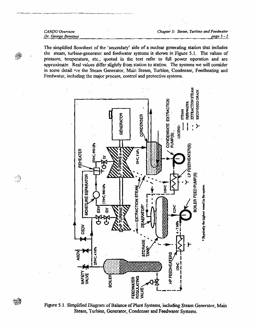
The simplified flowsheet of the <secondary' side of a nuclear generating station that includesthe steam, turbine-generator and feedwater systems is shown in Figure 5.1. The values ofpressure, temperature. etc., quoted in the text refer to full power operation and areapproximate. Real values differ slightly from station to station. The systems we will considerin some detail ne the Steam Generator, Main Stea.'n, Turbine, Condenser, Feedheating andFeedwater, including the major process, control and protective systems.
a::wf/)
ffi2o
zoi=~0:'
~
Figure 5.1. Simplified Diagram ofBalance ofPlant Systems, including Steam Generator, MainSteam, Turbine, Generator, Condenser and Feedwater Systems.
CANDU OverviewDr. George Bereznai
5.1 SwAM GENERATOR (BOILER)
Chapter 5: Steam, Turbine and Feedwaterpage 5 -3
During nonnal operation, the heat transport system transfers heat from the reactor to thesecondary coolant by way ofthe boilers. The boilers thus act as the principal heat sink: for thereactor. Reactor heat is transferred from the heat transport system to the boiler feedwater.As a result, the boiler produces steam to drive the turbine.
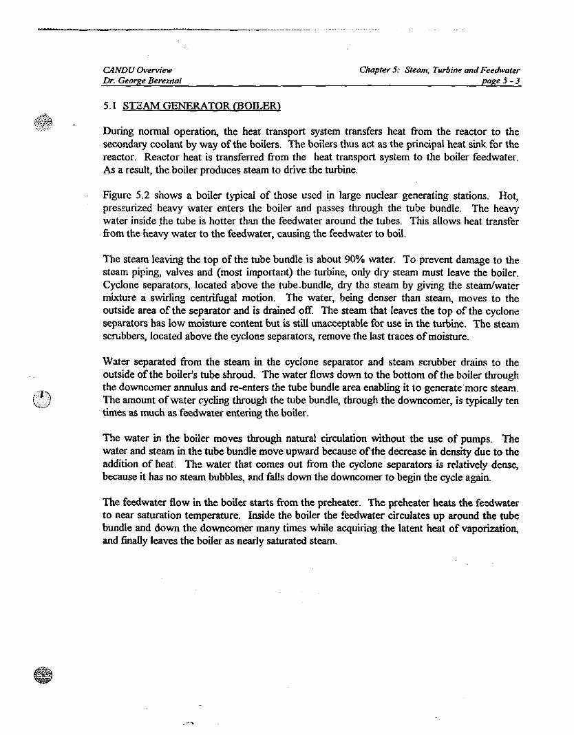
Figure 5.2 shows a boiler typical of those used in large nuclear generating stations. Hot,pressurized heavy water enters the boiler and passes through the tube bundle. .The heavywater inside the tube is hotter th'lll the feedwater around the tubes. This allows heat transferfrom the heavy water to the feedwater, causing the feedwater to boil.
The steam leaving the top of the tube bundle is about 90% water. To prevent damage to thesteam piping, valves and (most important) the turbine, only dry steam must leave the boiler.Cyclone separators, located above the tube.bundIe, dry the steam by giving the steam/watermixture a swirling centrifugal motion. The water, being denser than stearn, moves to theoutside area of the separator and is drained off. The steam that leaves the top of the cycloneseparators has low moisture content but is still unacceptable for use in the turbine. The steamscrubbers, located above the cyclone separators, remove the last traces of moisture.
Water separated from the steam in the cyclone separator and steam scrubber drains to theoutside ofthe boiler's tube shroud. The water flows down to the bottom ofthe boiler throughthe downcomer annulus and re-enters the tube bundle area enabling it to generate more steam.The amount ofwater cycling through the tube bundle, through the downcomer, is typically tentimes as much as feedwater entering the boiler.
The water in the boiler moves through natural circulation without the use of pumps. Thewater and steam in the tube bundle move upward because ofthe decrease in density due to theaddition of heat. The water that comes out from the cyclone separators is relatively dense,because it has no steam bubbles, ~.nd falls down the downcomer to begin the cycle again.
The feedwater flow in the boiler starts from the preheater. The preheater heats the feedwaterto near saturation temperature. Inside the boiler the feedwater circulates up around the tubebundle and down the downcomer many times while acquiring the latent heat of vaporization,and finally leaves the boiler as nearly saturated steam.
.-'
CANDU OverviewDr. George Bereznai
_.TER--I-
STEAM OUTI.ET
AAAAI I I II I I II I I I
1IJeE IlUNClE
++++I I I I'I I I I
Chapter 5: Steam, Turbine and Feedwaterpage5-4
110"""'-LEVElAT
100% Ff'
- NO.......LEVEl.AT.... Ff'
~
-STEAM___ =AND-WATER
IfEAVYWATEROUT
Figure 5.2. Typical Steam Generator or Boiler used in CANDU stations.
-------;--------
CANDU OverviewDr. George Bereznai
5.2 STEAM SYST2M
Chapter 5: Steam, Turbine and Feedwaterpage5-5
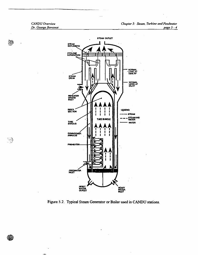
Figure 5.3 shows a simplified schematic of the steam system and components typical of a largeturbine unit. Safety valves installed on top of the boiler protect the steam system componentsfrom over pressure. The pressure from the boilers drives the steam to the high pressure (lIP)turbine. On route to the turbine the steam travels through several valves. Two of interest arethe emergency stop valves and the governor valves. The governor valve controls the quantityof steam flowing to the turbine, and therefore controls the speed of the turbine when notconnected to the grid, and when the generator is synchronized to the grid, it determines theelectrical output of the unit. Before reaching the governor valve the steam passes through theemergency stop valve. The emergency stop valve quickly stops the steam flow to the turbinein the event of a.'\ emergency that could damage the turbine.
GOVERHOAVAllIE
NOENSER
Figure 5.3. Simplified Steam System.
From the governor valve the steam passes through the lIP turbine. The lIP turbine convertsthe latent heat ofthe steam to mechanical energy. As the lIP turbine uses the latent heat in thesteam, the steam becomes wet (moist). Moisture content of more than 10% will causeexcessive erosion on the turbine blades. Removing the moisture in the steam allows furtherconversion ofthe remaining available energy. The lIPlLP arrangement of the turbine providesan opportunity at this stage to improve the quality of the steam to allow more energy to beconverted with risk ofdamage to the turbine.
Steam leaves the high pressure turbine at approximately 900 kPa and 170°C at 10"10 moisture.It passes to the moisture separator which removes the moisture in the steam. Steam leavingthe moisture separator has the same temperature and pressure a$ that at the turbine outlet butwithout moisture. It then passes thrOUgll a reheater to heat the steam. This increases thework that the steam can do in the Low Pressure (LP) turbine. The reheater uses steamdirectly from the boiler to heat the steam from the moisture separator. The steam leaves the
-----'--------------_ _ .
CANDU OverviewDr. George Bereznai
Chapter 5: Steam. Turbine and Feedwaterpage 5-6
reheater in a superheated condition at about 230°C and 900 kPa. Before entering the LPturbine, the steam passes through intercept valves. In a fashion similar to the emergency stopvalves, these valves shut off steam to the LP turbine in an emergency. Steam passes throughthe normally open intercept valves, passes through the iow pressure turbine, and is thenexhausted to the condenser at approximately 5 kPa(a), 35°C and 10% moisture.
Stopping the flow ofsteam to the turbine results in increased boiler pressure. This can happenon a turbine trip. Reducing reactor power and getting rid of the steam prevents excessiveboiler pressure build up. Adjusting the reactor power level too low can poison out thereactor. However, if the power level is kept above 60% full power, the reactor can keepoperating. Providing an alternative heat sink, while operating at this power level, will preventa boiler pressure increase. The alternate heat sink can be provided by blowing the steam toatmosphere or directly to the condenser. .All CANDU units have large steam reject valves ableto discharge steam either to the atmosphere or to the condenser with the reactor at 60% FPThey are also equipped with smaller steam reject valves that are able to discharge steam to theatmosphere at the decay heat power level, if the condenser is unavailable.
Main Steam
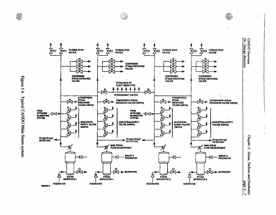
The steam system of a typical CANDU unit is shown on Figure 5.4. All the valves and othermajor equipment shown on the previous simplified diagrams can be identified, and the ones ofparticular relevance to the operation ofthe Main Steam system are discussed in the followingsections.
Main steam safety valves are provided on each steam main to protect the steam system and thesteam generators from overpressure.
Prevision is made to detect heavy water in the steam. Connections from each steam line to theD20 in light water detection system provide a continuous on-line measurement eapability.Each sampling line also has a low pressure low temperature grab sample valve for periodicassessment of steam chemistry and tritium content.
It may be desirable to isolate anyone pair of steam generators following a steaiJl generatortube rupture, or a process failure while operating with a steam generator tube leak. This isaccomplished by closing the appropriate turbine stop valves on the steam lines from two steamgenerators (the steam generator with the tube leak and its companion) and the appropriatesteam main interconnect valves by remote manual operation from the main control room.Steam supply to balance of plant steam loads are provided by connections between the steammain interconnect valves. Closure of both steam main interconnect valves also isolates thesesteam loads.
'@"'¥[tl'>:;(,.,
.:' ....,....;.,i(jjJ
J~~F'
~'fH!t~~;J
Q{l~.,~
\:l
~~tiS''"~~
., '"~t, ~
,,~
~QQ~~ c::~ ~~~n'2,
MAN 8TEAll1A.'ETY'AlVE8(M8''''
TURBINE 8TOPVAlVEa
A1lfOBPHERIC STEAMDlaCHARaE'Al'" (-I
"--Vl...- " .......~FEEDWATER
J-l>I<I-+-~
CI1NDENSE~STEAM DISCHARQEVAlVES
STEAMQENERATOR3
I .. ~TC'fcr~HzC>..../ ..... 8TEAIIJIll FLOW MEASU~EMENT
""'" STEAMIAFETYVALVE8(MIla..,
CX)NOENSEASTEAM DtSCHAROEVAlVES
TURBINE BTOPVALVES
ATMOSPHEAlC~_8T"".r--v'....r-':"" aaCHAAae
.AlVE' (AllOYoI
nEOWATER
""""NITROGENIlIRlICETlNtlSYSTEM
MAIN 8T15AM SAmYVAlVEI IMa",,)
CClNOENIERITEAM DISCHARGEVAlVEI
lIl~EDF.PlN/T USElla (TYP)
Tl,;ASINE 8TOPVAlVES
IN'TERCONNEOTVAlVEB
AnI08PHER)O ITEAMDl'SCHAAGE VAlVES (A8DVa)
GROUP :II-'-KI- FfeowATER
1-------1~1Il D20 IN H2O I., DETECTION II(
~ MNN8TEAM:Jl1 FLO«MEAWREMEM'
f~ Ill.OWDC1M4
tTEAMQENEAATOA4
FEEOW'ATER '
IlAlN 8T15AM8AFETY VAt.YES
(11II''''
_IERlTEAII OIICHAAGEY,AlVEI
TURBIHII STOPVALVES
ATMOSPHERICI ..-vI _ IT....r--v--.r- D18CHAAGE
VAl... (AllOVI)
FEEOWATER,1Ot'1'-'
lIlD,ONHzOOETIfcTION
FIlOlINITIIlOSlIUNK1!TllQ"STEM
fv.;:.
~[(j
~~l!?::>en
~
1
._-------_•..._-_.__..._..----------_. __ .-
CANDU OverviewDr. George Bereznai
Steam Generator Blowdown
Chapter 5: Steam, Turbine and Feedwaterpage 5-8
The steam generator blowdown system is provided to limit impurities in the steam generator.To accomplish this, provision has been made for a continuous blowdown, from the secondaryside, at a mas~ flowrate equal to 0.1 percent of the steaming rate. In the event that thefeedwater quality becomes poor, the blowdown rate can be increased to 0.3% of the steamingrate. Blowdown flow is taken from the downcomer area and the tube free lane. Shutoffvalves are provided to close off flow from either of these areas. The blowdown rate iscontrolled by a control valve. located in the turbine building. Environmentally and seismicallyqualified isolation valves are provided in each blowdown line to prevent draining of the steamgenerators, in the unlikely event ofa line break. These valves automatically close on initiationofGroup 2 feedwater. The steam generator blowdown discharges into tanks which reduce thetemperature and pressure of the blowdown water and provide an effective separation offlashed steam from the water.
Condenser Steam Discharge Valves
The main function ofthese valves is to discharge live steam to the condenser on loss of turbineso that the reactor can continue to operate at the power required to prevent a 'poison-out'.They are also used to discharge steam on a loss of line, or cn R turbine trip, so that the mainsteam safety valves do not lift. The valves function as follows:
a. During nonnal operation they operate on the pressure control mode, with an offset to biasthem closed.
b. During 'poison-prevent', their steady state opening is proportional to the power mismatchbetween the poison-prevent reactor power level and actual turbine steam consumption.
c. On a turbine trip, they are first opened fully and then returned to the pressure controlmode.
d. During shutdown to provide a heat sink through the condenser for decay heat removal.
Operation of the condenser steam discharge valves is conditional on the maintenance ofadequate condenser vacuum.
Atmospheric Steam Discharge Valves
These low capacity valves are used to control steam generator pressure via the steam pressurecontrol program. They are opened in proportion to the pressure error, normaUy with an offsetin the steam pressure setpoint. These valves may also be used to provide a heat sink duringshutdown for decay heat removal when the main condenser is unavailable.
..~ ".
--------_.._-", .... __ .---- .. _~
CANDU OverviewDr. George Bereznai
Steam Generator Pressure Control
Chapter 5: Steam, Turbine and Feedwaterpage 5 - 9
During normal operation, steam pressure is primarily controlled by adjusting reactor power. Iffor some reason the reactor regulating system does not allow the reactor to respond topressure controller demands, or if a r~actor power reduction occurs because of a trip, astepback, or a setback, the reactor setpoint is controlled directly by the respective reductionsignal, and the 'normal' mode of control of steam generator secondary side pressure isintenupted. Steam pressure control switches to the 'alternate' mode of adjusting the plantloads.
Turbine Control
When the plant is in the 'nonnal' mode, the turbine governor valves are controlled through theunit power regulator program; i.e., the unit power regulator calculates what the valve setpointshould be and pulses to that position. If'the plant is in the 'alternate' mode, the stearngenerator pressure control system controls the turbine in response to the steam pressure error,steam pressure error rate ofchange, and the rate ofchange ofreactcr power.
The turbine has a low stearn pressure unloader eAiemal to the control computers. Thisoverrides directly the turbine governor action including the steam generator pressure controlsignal, and causes a fast ronback ofthe turbine.
5.3 TURBINE
The turbine converts the pressure of the steam to rotational energy. This conversion involvestransformation of the heat energy into high velocity steam through fixed nozzles. The fixednozzles form the turbine fixed blades. The high velocity steam directs its kinetic energy on tothe moving blades forcing them to move (rotate).
From the first set of fixed and moving blades, the steam then moves through succeeding setsto repeat the process of energy conversions. A set of fixed blade nozzles and moving bladeconstitutes a turbine stage. It is common to use a number ofstages in a turbine to convert theuseful heat energy in the steam into mechanical energy. The moving blades are attached to ablade wheel and the blade wheel is mounted on the rotor shaft. The high velocity steamleaving the nozzle drives the wheel which in tum rotates the shaft.
The turbine wheels and casing get progressively larger as the steam goes from the highpressure end to the low pressure end. This is necessary to accommodate the expansion of thestearn as a direct result of pressure and temperature reduction. Steam entering the highpressure end of a modem nuclear turbine set is typically around 250°C and 4000 kPa. At thistemperature and pressure one kilogram of steam occupies 0.05 mJ
• The steam leaving theturbine unit and entering the condenser is typically around 35°C and 5 kPa(a). At thistemperature and pressure one kilogram of steam occupies 25.2 mJ
• The steam expandsroughly five hundred times from the inlet to the exhaust. In a large turbine generator set it isusually not possible to accommodate the large volume of steam in one turbine unit. Normallyone high pressure turbine will exhaust to two or more low pressure turbines in combinationwith the double flow design.
------------ ,---, _- -
CANDU OverviewDr. George Bereznai
Chapter 5: Steam, Turbine and Feedwaterpage 5-10
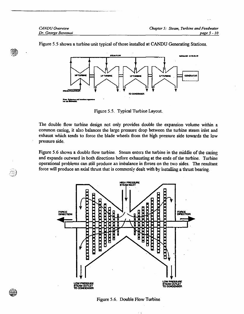
Figure 5.5 shows a turbine unit typical of those installed at CANDU Generating Stations.
.........ow
'-J.LPTUAIIlNE lI'~ IJI'TUAIltE
~~~,~~~~~+-_......10 CCNCBCSEA
Figure 5.5. Typical Turbine Layout.
The double flow turbine design not only provides double the expansion volume within acommon casing, it also balances the large pressure drop between the turbine steam inlet andexhaust which tends to force the blade wheels from the high pressure side towards the lowpressure side.
Figure 5.6 shows a doubl:: flow turbine. Steam enters the turbine in the middle of the casingand expands outward in both directions before eJ'.hausting at the ends of the turbine. Turbineoperational problems can stili produce an imbalance in forces on the two sides. The resultantforce will produce an axial thrust that is commonly dealt with by installing a thrust bearing.
~ ~
~:....L--e-lJ-Q..a-c-lHI-i-+~~_Q_I:;r_.a...~
!~'
!Figure 5.6. Double Flow Turbine
CANDU OvetviewDr. George Bereznai
5.4 CONDENSER
Chapter 5: Steam. Turbine and Feedwaterpage 5-lJ
The condenser is the final destination for most of the steam produced in the boiler, where it isturned back into water. The large decrease in volume creates a vacuum in the condenser.This permits steam flow from the high pressure boiler to the low pressure condenser so theturbine can extract mechanical energy efficiently.
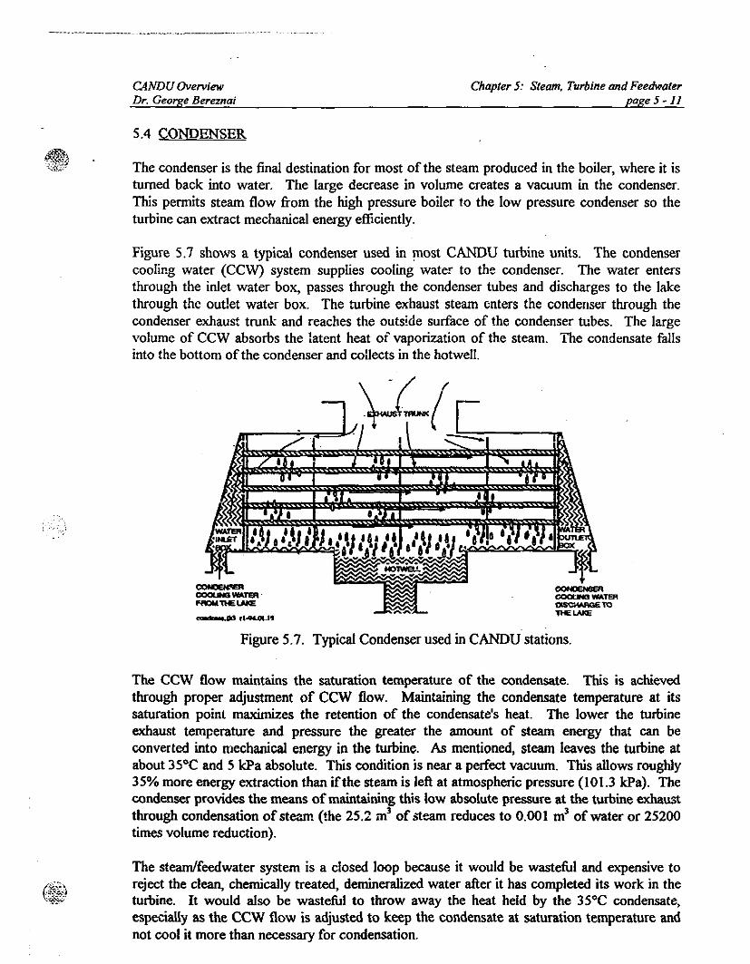
Figure 5.7 shows a typical condenser used in most CANDU turbine units. The condensercooling water (CCW) system supplies cooling water to the condenser. The water entersthrough the inlet water box, passes through the condenser tubes and discharges to the lakethrough the outlet water box. The turbine exhaust steam enters the condenser through thecondenser exhaust trunk and reaches the outside surface of the condenser tubes. The largevolume of CCW absorbs the latent heat of vaporization of the steam. The condensate fallsinto the bottom ofthe condenser and collects in the hotwell.
~dd ,......OI.lt
Figure 5.7. Typical Condenser used in CANDU stations.
The CCW flow maintains the saturation temperature of the condensate. This is achievedthrough proper adjustment of CCW flow. Maintaining the condensate temperature at itssaturation point maximizes the retention of the condensate's heat. The lower the turbineexhaust temperature and pressure the greater the amount of steam energy that can beconverted into mechanical energy in the turbine. AJ> mentioned, steam leaves the turbine atabout 35°C and 5 \cPa absolute. This condition is near a perfect vacuum. This allows roughly35% more energy extraction than ifthe steam is left at atmospheric pressure (101.3 \cPa). Thecondenser provides the means of maintaining this low absolute pressure at the turbine exhaustthrough condensation of steam (the 25.2 m3 of steam reduces to 0.001 m3 of water or 25200times volume reduction).
The steam/feedwater system is a closed loop because it would be wasteful and expensive toreject the clean, chemically treated, demineralized water after it has completed its work in theturbine. It would also be wasteful to throwaway the heat held by the 35°C condensate,especially as the CCW flow is adjusted to keep the condensate at saturation temperature andnot cool it more than necessary for condensation.
CANDU OverviewDr. George Bereznai
5.5 FEEDWATER SYSTEM
Chapter 5: Steam. Turbine and FeedwaterpageS -12
The feedwater system supplies normal feedwater to the steam generators. The feedwatersystem comprises the main feedwater pumps on Class N power and a diesel-driven auxiliaryfeedwater pump. The feedwater is demineralized and preheated light water. The feedwaterlines run from the feedwater regulating valve station in the turbine building to the reactorbuilding and hence, to each steam generator.
Figure 5.1 shows a simplified steam system and boiler feedwater system. The feedwatersystem is generally divided into three parts: .
• low pressure feedheating system;
• deaerator and storage tank;
• high pressure feedheating system.
The water leaving the condenser is at relatively low temperature and pressure. A series ofheat exchangers raises the condensate temperature to 170°C. The preheaters then increase thetemperature to 240°C (almost saturation temperature in the boiler). A set of pumps, known asboiler feed pumps (BFP), force the feedwater into the boilers operating at 4000 kPa. .
Low Pressure Feedheating System
The first stage in the boiler feedwater heating is through the LP feedheating system. Thecondensate extraction pump (CEP) delivers the condensate from the condenser hotwel! to theLP feedheaters. The low pressure feedheating system gets its name from the low pressurecondition of the feedwater, at about 1400 kPa, compared to the 4000 kPa in the boiler.
The LP feedheaters use extraction steam (wet steam removed from the turbine before itreaches the exhaust end) from the LP turbines as their heating medium. The extraction steamtransfers its latent heat ofvaporization to the feedwater through a process similar to that in thecondenser. A series of low pressure feedheaters heat the feedwater. The extractiof' steamcondenses in the shell of the heater. A separate pump recovers this condensate by pumping itto the condenser hotwell. The feedwater leaves the last LP feedheater at approximately 80°Cto 100°C. The heated feedwater then goes to the next stage ofthe feedheating process.
Deaerator and Storage Tank
The deaerator is the next stage in the feedwater heating process. This is the highest vessel inthe· system. The deaerator adds heat to and removes non-condensable gases from thefeedwater. Some of these gases can increase the corrosion rate of the metals in the highpressure feedheating system and boiler. All non-condensable gases will take-up space in thesteam system we wish to occupy with steam.
CANDU OverviewDr. George Bereznai
Chapter 5: Steam, Turbine and Feedwaterpage5-13
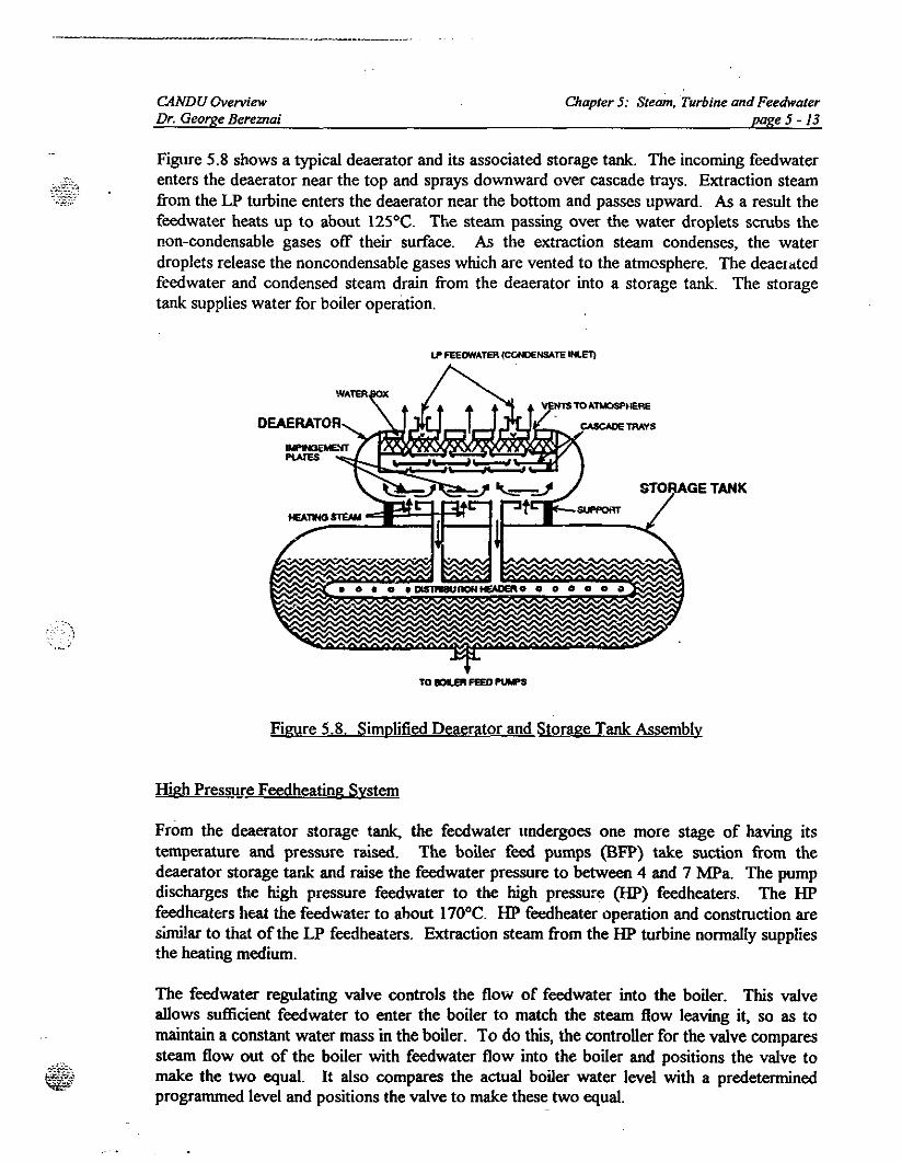
Figure 5.8 shows a typical deaerator and its associated storage tank. The incoming feedwaterenters the deaerator near the top and sprays downward over cascade trays. Extraction steamfrom the LP turbine enters the deaerator near the bottom and passes upward. As a result thefeedwater heats up to about 125°C. The steam passing over the water droplets scrubs thenon-condensable gases off their surface. As the extraction steam condenses, the waterdroplets release the noncondensable gases which are vented to the atmosphere. The deaeratedfeedwater and condensed steam drain from the deaerator into a storage tank. The storagetank supplies water for boiler operation.
LP FEEOW'ATeR (CONDENSATE INlET)
STORAGE TANK
TO IOILEPI FEED P\APS
Figure 5.8. Simplified Deaerator and Storage Tank Assembly
High Pressure Feedheating System
From the deaerator storage tank, the fecdwater undergoes one more stage of having itstemperature and pressure raised. The boiler feed pumps (BFP) take suction from thedeaerator storage tank and raise the feedwater pressure to between 4 and 7 MPa. The pumpdischarges the high pressure feedwater to the high pressure (lIP) feedheaters. The lIPfeedheaters heal the feedwater to about 170°C. lIP feedheater operation and construction aresimilar to that ofthe LP feedheaters. Extraction steam from the lIP turbine normally suppliesthe heating medium.
The feedwater regulating valve controls the flow of feedwater into the boiler. This valveallows sufficient feedwater to enter the boiler to match the steam flow leaving it, so as tomaintain a constant water mass in the boiler. To do this, the controller for the valve comparessteam flow out of the boiler with feedwater flow into the boiler and positions the valve tomake the two equal. It also compares the actual boiler water level with a predeterminedprogrammed level and positions the valve to make these two equal.
CANDU OverviewDr. George Bereznai
Chapter 5: Steam, Turbine and Feedwaterpage 5 - 14
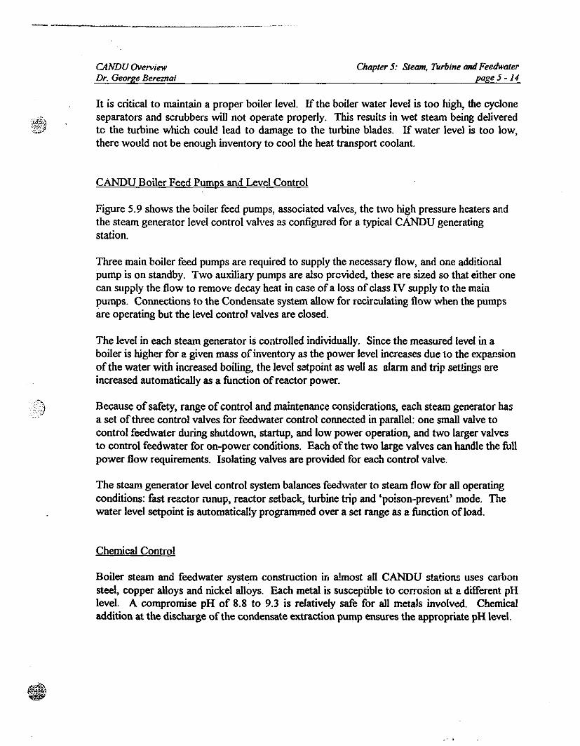
It is critical to maintain a proper boiler level. If the boiler water level is too high, the cycloneseparators and scrubbers will not operate properly. This results in wet steam being deliveredto the turbine whioh could lead to damage to the turbine blades. If water level is too low,there would not be enough inventory to cool the heat transport coolant.
CANDU Boiler Feed Pumps and Level Control
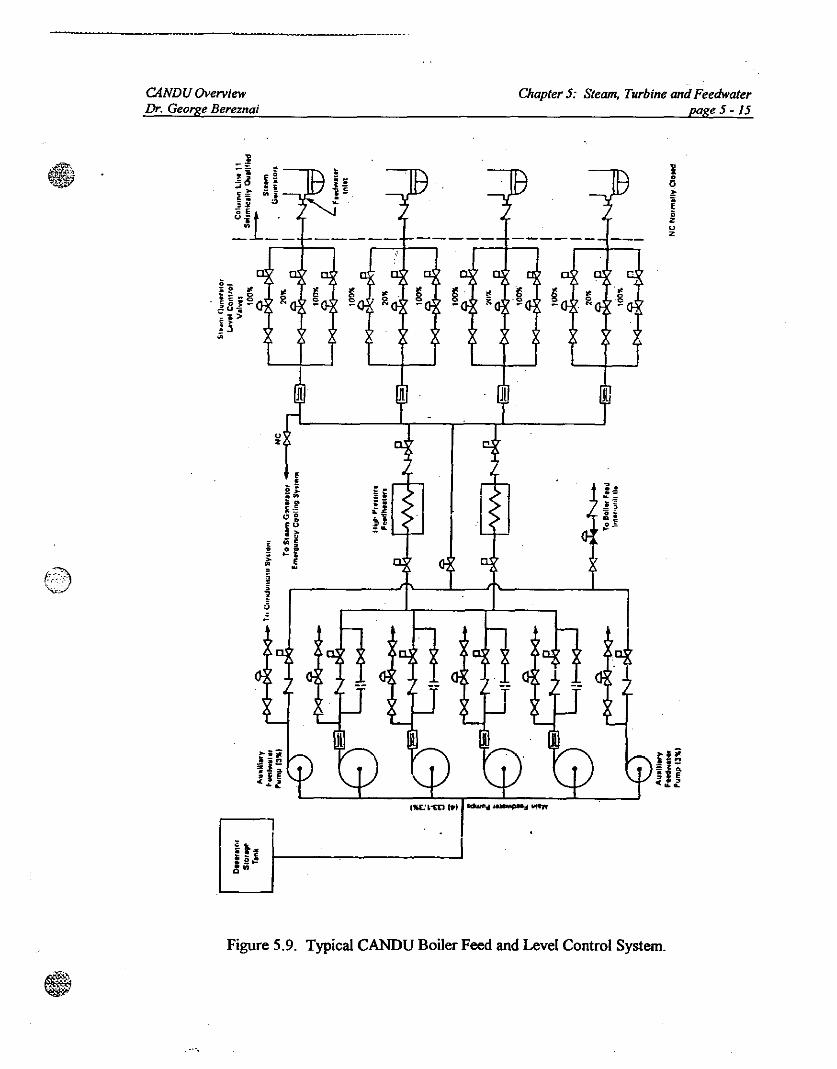
Figure 5.9 shows the boiler feed pumps, associated valves, the two high pressure heaters andthe steam generator level control valves as configured for a typical cANDu generatingstation.
Three main boiler feed pumps are required to supply the neoessary flow, and one additionalpump is on standby. Two auxiliary pumps are also provided, these are sized so that either onecan supply the flow to remove decay heat in case ofa loss of class IV supply to the mainpumps. Connections to the Condensate system allow for recirculating flow when the pumpsare operating but the level control valves are closed.
The level in each steam generator is controlled individually. Since the measured level in aboiler is higher for a given mass ofinventory as the power level increases due to the expansionofthe water with increased boiling, the level setpoint as well as alarm and trip settings areincreased automatically as a function ofreactor power.
Because of safety, range ofcontrol and maintenance considerations, each stearn generator hasa set ofthree control valves for feedwater control connected in parallel: one small valve tocontrol feedwater during shutdown, startup, and low power operation, and two larger valvesto control feedwater for on-power conditions. Each ofthe two large valves can handle the fullpower flow requirements. Isolating valves are provided for each control valve.
The steam generator level control system balances feedwater to steam flow for all operatingconditions: fast reactor runup, reactor setback, turbine trip and 'poison-prevent' mode. Thewater level setpoint is automatically programmed over a set range as a function ofload.
Chemical Control
Boiler steam and feedwater system construction in almost all CANDU stations uses carbonsteel, copper alloys and nickel alloys. Each metal is susceptible to corrosion at a different pHlevel. A compromise pH of 8.8 to 9.3 is relatively safe for all metals involved. Chemicaladdition at the discharge of the condensate extraction pump ensures the appropriate pH level.
CANDU OverviewDr. George Bereznai
Chapter J: Steam, Turbine andFeedwaterpage J-15
e 11 ~ '" ~ ~ ~ ~ ~0=. .. 8 01< ~0
~ ~ .~
S~ - N
.>5
Jl
uz
Jl
QIIJ!" f---------
Figure 5.9. Typical CANDU Boiler Feed and Level Control System.
-_._--._--
CANDU OverviewDr. George Bereznai
Other methods used to prevent corrosion are:
• oxygen removal from the system,
• chemical addition to react with oxygen.
Chapter 5: Steam, Turbine and Feedwaterpage 5 -16
Most oxygen is removed from the system by the scrubbing action of the deaerator. Hydrazineadditior, to the feedwater, after the deaerator, removes the remaining oxygen. Its reactionwith oxygen produces noncorrosive nitrogen gas and water. Unfortunately, hydrazine alsoproduces ammonia which attacks copper alloys.
High quality feedwater and makeup water is vital as low quality will produce deposits in theboiler and turbine causing:
• reduced heat transfer because ofan insulating scale layer on the boiler tube surface;
• increased risk of stress corrosion cracking;
• corrosion oftubes and other components.
AlI will shorten the life of the boilers and turbines. Demineralization, deaeration, oxygenremoval and pH control ensure that we have good quality boiler water. A blowdown systemin each boiler allows removal of a.'ly impurities that collect in the boilers. This systemminimizes accumulation of impurities by draining the contlllt'Joated water out of the boiler.Blowdown can be intermittent or continuous, depending on the water condition.
5.6 GENERATOR
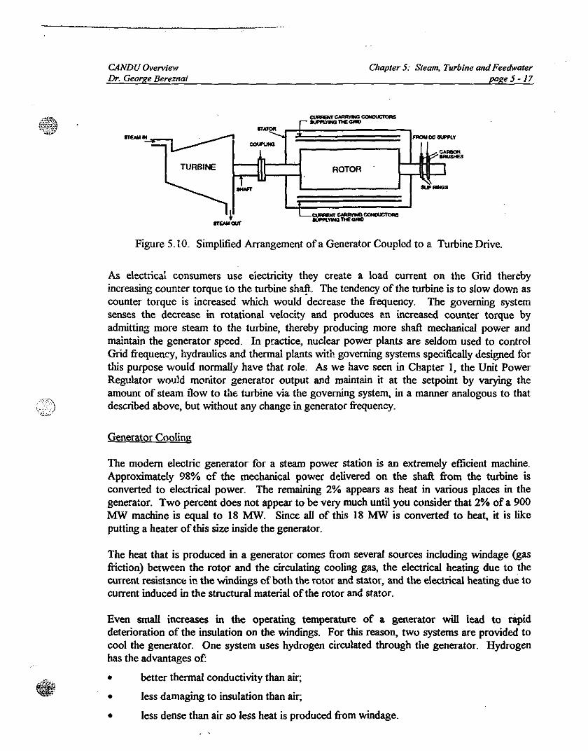
Figure 5.10 shows a simplified arrangement ofa generator c.oupled to a steam turbine drive.The stationary conductors (coils) and the associated iron cores are referred to as a stator.Conductors (coils) and the associate iron core mounted on the shaft are referred to as a rotor.
Insulated slip rings on the shaft transfer DC current to create a magnetic field in the rotor.The stator windings act as the conductors for the main generator current while the turbineprovides the mechanical torque on the shaft of the generator. The rotating motion providedby the shaft produces the relative motion between the rotor magnetic field and the statorconductors. As a result, a voltage is induced in the stator conductors and transferred to thetransmission lines through a step-up transformer.
In a generator, the rotor velocity determines the frequency. When the generator is connectedto the grid the frequency is fixed at 50 or 60 Hz depending on the bulk electric system. Sincethe frequency for the Grid is controlled at a fixed value, the velocity of the rotor is keptconstant.
------,...---------.,..---------
CANDU OverviewDr. George Bereznai
Chapter 5: Steam, Turbine andFeedwaterpage5-}7
sr...~r ...........- ....
"""'DOcouPUHO
h 17:II ROTOR I
.Lr .. ...L_~CClNOUCTOIlS
TURBINE
Figure 5.10. Simplified Arrangement ofa Generator Coupled to a Turbine Drive.
As electrical consumers use eiectricity they create a load current on the Grid therebyincreasing counter torque to the turbine sh~. The tendency of the turbine is to slow down ascounter torque is increased which would decrease the frequency. The governing systemsenses the decrease in rotational velocity and produces l!n increased counter torque byadmitting more stearn to the turbine, thereby producing more shaft mechanical power andmaintain the generator speed. In practice, nuclear power plants are seldom used to controlGrid frequency, hydraulics and thermal plants with governing systems specifically designed fortins purpose would normally have that role. As we have seen in Chapter I, the Unit PowerRegulator would monitor generator output and maintain it at the setpoint by varying theamount of steam now to the turbine via the governing system, in a manner analogous to thatdescribed above, but without any change in generator frequency.
Generator Cooling
The modern electric generator for a stearn power station is an extremely efficient machine.Approximately 98% of the mechanical power delivered on the shaft from the turbine isconverted to eleLtrical power. The remaining 2% appears as heat in various places in thegenerator. Two percent does not appear to be very much until you consider that 2% of a 900MW machine is equal to 18 MW. Since all of this 18 MW is converted to heat, it is likeputting a heater of this size inside the generator.
The heat that is produced in a generator comes from several sources including windage (gasmction) between the rotor and the circulating cooling gas, the electrical heating due to thecurrent resistance in the windings of both the fOtor and stator, and the electrical heating due tocurrent induced in the structural material of the rotor and stator.
Even small increases in the operating temperature of a generator will lead to rapiddeterioration of the insulation on the windings. For this reason, two systems are provided tocool the generator. One system uses hydrogen circulated through the generator. Hydrogenhas the advantages of:
•••
better thermal conductivity than air;
less damaging to insulation than air;
less dense than air so less heat is produced from windage.
.. '.
--- -_. -_._---
CANDU OverviewDr. George Bereznai
Chapter 5: Steam, Turbine and Feedwaterpage 5 -18
The disadvantage i~ that it is explosive when mixed with air. To avoid this hazard, thegenerator requires very good seals to prevent air inIeakage or leakage of hydrogen out of thegenerator.
By itself, the hydrogen cooling sy~tem is inadequate. To complement it, a stator cooling watersystem is also provided. The conductors in the stator are hollow and water is circulatedthrough them. This water has to be exceptionally pure to prevent leakage of current from thestator conductors to ground through the coolant.
Turning Gear
When a turbine comes to rest, after operating, the cooler and denser steam tends to collect inthe lower half of the cylinder and makes the lower half of the rotor cool quicker than the upperhalf This causes the shaft to 'hog' (bend upwards). When at rest and cool, the shaft willbegin to 'sag' under its own weight. If the turbine shaft is not rotated, hogging, especiallyabove a critical temperature, can become permanent and the shaft would have to be sent to themanufacturer for heat treatment and straightening Sagging does not usually becomepermanent but it takes time to recover the sag. To prevent a bent shaft due to sag or hog theshaft is rotated by a turning gear which is a motor driven gear train mechanism on the turbinegenerator shaft.
Lubrication System
Each unit of the turbine and the generator has its own rotor/shaft that is supported at each endby journal bearings. Journal bearings get hot due to friction and heat conduction along theshaft from hot parts of the turbine. The journal bearings are normally lined with white metalknown as antifriction metal or babbitt, which is a lead-tin alloy with a melting point that can beas low as 182°C. A centralized lubricating system is employed to protect the bearings fromdamage due to metal to metal contact and high temperature. This extends the life of thebearings and reduces the chance offailure. A bearing failure is a very serious incident as far asthe turbine-generator is concerned and would cause extensive damage. For this reason it isalways important to have sufficient oil flow through the bearings for lubrication and coolingpurposes.
5.7 CONVENTIONAL PLANT SERVICES
Conventional plant services include water supply, heating, ventilation, air conditioning,chlorinating, fire protection, compressed gases and electric power systems.
The water supply systems provide cooling water, demineralized water and domestic water tostation users.
Heating, ventilation and air conditioning is provided to ensure a controlled environment duringwinter and summer.
CANDU OverviewDr. George Bereznai
Chapter 5: Steam, Turbine and Feedwaterpage 5 -19
Chlorination systems are used for treatment of domestic water, fresh water supply to the pretreatment plant, condenser cooling water and raw service water. Separate chlorinationsystems are provided, in the water treatment plant, in the Group 1 pumphouse, and the Group2 pumphouse.
Compressed gas systems supply compressed air, helium, nitrogen and carbon dioxide gases,an:! vacuum to all plant systems as required.
Provision is made to detect heavy water in the steam. Connection from each steam line to theD20 in light water detection system provide a continuous on-line measurement capability.Each sampling line also has a low pressure low temperature grab sample valve for periodicassessment of steaill chemistry and tritium content.
..-


![1 Eric Grol SystemAnalysis.ppt [Read-Only] library/events/2008/seca... · • Single pass SOFC ... Boiler Feedwater Supercritical Steam Condenser Steam Turbine Air Heat Recovery N](https://img.pdfslide.us/doc/110x75/5abaa5427f8b9a76038bc126/1-eric-grol-read-only-libraryevents2008seca-single-pass-sofc-boiler.jpg)