Embed Size (px)
Citation preview
8/4/2019 Chapter3 Chlorine
http://slidepdf.com/reader/full/chapter3-chlorine 1/35
0
Chapter 3
CHLORINE

8/4/2019 Chapter3 Chlorine
http://slidepdf.com/reader/full/chapter3-chlorine 2/35
1
Introduction
Water disinfection by chlorination, massively introduced worldwide in the early twentieth
century, set off a technological revolution in water treatment, complementing the known and used process of filtration. As already stated in a previous chapter, it was responsible for increasing life
expectancy by 50% in the developed countries.
The keys to its success are its easy accessibility in almost all of the world’s countries,
reasonable cost, capacity for oxidation –the mechanism for destroying organic matter- , and residualeffect. All of this allows it in a fairly simple way to ensure the harmlessness of drinking water from
the moment of its production to its use, thereby benefiting not only small systems, but also large
cities with extensive distribution networks.
Although chlorine and chlorine-related substances are not perfect disinfectants, they have anumber of characteristics that make them highly valuable:
• They have broad-spectrum germicidal potency.
• They show a good degree of persistence in water distribution systems. Their easily
measurable residual properties can be monitored in water networks after treatment and/or
delivery to users.
• The feeding equipment is simple, reliable and inexpensive. At the small community level,
there are also a number of “appropriate technology” devices that local operators are able to
handle easily.
• Chlorine and chlorine-based compounds are easily found, even in remote areas of developing
countries.
• This method is economic and cost-effective.
The following chlorine-related compounds for water disinfection can be found in the market:
• gaseous chlorine
• chlorinated lime
• sodium hypochlorite
• calcium hypochlorite
The choice of these products will depend on the answer that is given to these questions:
• How much disinfectant is needed?
• How easily is the product obtained?
• Does the necessary technical capacity exist for using, operating and maintaining theequipment?
• Are the necessary resources available to keep workers from being exposed to health risks
during the storage and handling of the substance?
• Does the economic and financial capacity exist to assume the investment, operating and
maintenance costs?
To answer these questions, the technical, economic and social conditions at the target site
will need to be studied.
The amount of disinfectant that will be needed will depend upon the water flow to be treated,
the required dosage according to the water quality and the country’s drinking water standards.
8/4/2019 Chapter3 Chlorine
http://slidepdf.com/reader/full/chapter3-chlorine 3/35
2
There is an unwritten rule, however, that limits the amount of chlorine gas that can be used as
compared with other chlorine compounds. That ceiling stands at a volume of 500 /day. Chlorine
gas is not recommendable for flows of less than 500 m3/day. This means that considering a supply
of 100 liters a day per inhabitant, typical of the rural environment, the use of chlorine gas isrecommendable only for populations of over 5,000 people.
The supply of the product definitely affects the choice that is made. Inasmuch as the rural
areas are generally far from the cities and difficult to reach, it may be necessary to decide on
another disinfectant or to prepare sodium hypochlorite on site.
In making a selection, available technical capacity must also be considered. The operation of
chlorine gas facilities requires trained and competent personnel. These are hard to find and difficult
to pay in rural areas. Furthermore, continuous and stable electric power is needed to operate the
pumps for this system.
The extreme danger posed by gaseous chlorine means that it is important to have thetechnical means and trained personnel to minimize and control the risks inherent to installations of
this kind. An undiscovered leak that is not controlled in time could cause serious accidents that
could endanger human lives.
To conclude, in the case of the disinfection costs, it will be necessary to consider the
circumstances. A more expensive solution could be advisable, for example, if it were more reliable,
durable and simple to operate and its spare parts and supplies were more easily obtained. It is
usually worth paying a little more if the additional investment ensures the success of the operation;
in the long run, it may even turn out to be cheaper. Inasmuch as the concentrations of active
chlorine in the different products vary, the needed volume of that active chlorine will also vary,
meaning that the transportation costs to be considered will also differ according to the volumes
needed. In any case, health must be the main consideration when choosing the most appropriatealternative.
Properties of the chlorine products and description of the method
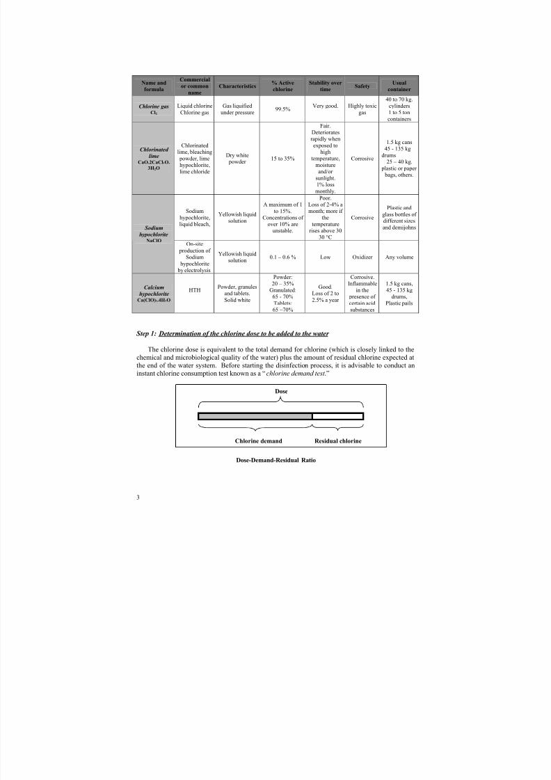
Commercial chlorine products are obtained by different methods, which determine their
concentration of active chlorine, presentation and stability. The comparative table below lists the
major properties of each.
The concept of “active chlorine” that is used throughout this chapter should be explained
here. “Active chlorine” is the percentage by weight of molecular chlorine rendered by a molecule
of the compound. If, for example, a certain solution contains 10% active chlorine, this is equivalent
to 10 g of chlorine gas being bubbled (and totally absorbed) in 100 ml (100 g) of water without anyloss, hence the “10%.” The word “active” means that this chlorine is ready to enter into action; it is
prepared and “waiting” to attack the organic matter or any other substance that it is capable of
oxidizing.
Disinfection using chlorine and chlorine-based compounds should be carried out in three
successive steps that will vary to some degree according to the product that is used:
Step 1: Determination of the chlorine dose to be added to the water system
Step 2: Preparation of non-gas solutions
Step 3: Feeder calibration.
8/4/2019 Chapter3 Chlorine
http://slidepdf.com/reader/full/chapter3-chlorine 4/35
3
Name and
formula
Commercial
or common
name
Characteristics% Active
chlorine
Stability over
timeSafety
Usual
container
Chlorine gasCl2
Liquid chlorine
Chlorine gas
Gas liquified
under pressure99.5%
Very good. Highly toxic
gas
40 to 70 kg.
cylinders1 to 5 toncontainers
Chlorinated
limeCaO.2CaCl2O.
3H2O
Chlorinatedlime, bleaching
powder, limehypochlorite,
lime chloride
Dry white powder
15 to 35%
Fair.Deteriorates
rapidly whenexposed to
hightemperature,
moistureand/or
sunlight.1% loss
monthly.
Corrosive
1.5 kg cans45 - 135 kg
drums25 – 40 kg.
plastic or paper bags, others.
Sodium
hypochlorite,liquid bleach,
Yellowish liquid
solution
A maximum of 1
to 15%.Concentrations of
over 10% areunstable.
Poor.Loss of 2-4% amonth; more if
thetemperature
rises above 3030 °C
Corrosive
Plastic and
glass bottles of different sizesand demijohns Sodium
hypochloriteNaClO
On-site
production of Sodium
hypochlorite by electrolysis
Yellowish liquidsolution
0.1 – 0.6 % Low Oxidizer Any volume
Calciumhypochlorite
Ca(ClO)2.4H2O
HTH Powder, granulesand tablets.
Solid white
Powder:20 – 35%
Granulated:65 - 70%
Tablets:65 –70%
Good.Loss of 2 to
2.5% a year
Corrosive.Inflammable
in the presence of
certain acidsubstances
1.5 kg cans,
45 - 135 kgdrums,
Plastic pails
Step 1: Determination of the chlorine dose to be added to the water
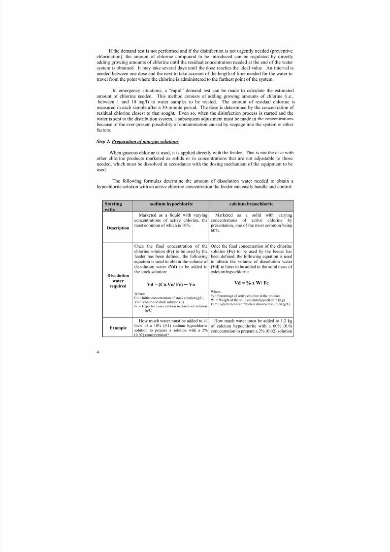
The chlorine dose is equivalent to the total demand for chlorine (which is closely linked to the
chemical and microbiological quality of the water) plus the amount of residual chlorine expected at
the end of the water system. Before starting the disinfection process, it is advisable to conduct an
instant chlorine consumption test known as a “chlorine demand test .”
Dose-Demand-Residual Ratio
Chlorine demand Residual chlorine
Dose
8/4/2019 Chapter3 Chlorine
http://slidepdf.com/reader/full/chapter3-chlorine 5/35
4
If the demand test is not performed and if the disinfection is not urgently needed (preventive
chlorination), the amount of chlorine compound to be introduced can be regulated by directly
adding growing amounts of chlorine until the residual concentration needed at the end of the water
system is obtained. It may take several days until the dose reaches the ideal value. An interval isneeded between one dose and the next to take account of the length of time needed for the water to
travel from the point where the chlorine is administered to the farthest point of the system.
In emergency situations, a “rapid” demand test can be made to calculate the estimated
amount of chlorine needed. This method consists of adding growing amounts of chlorine (i.e.,
between 1 and 10 mg/l) to water samples to be treated. The amount of residual chlorine is
measured in each sample after a 30-minute period. The dose is determined by the concentration of
residual chlorine closest to that sought. Even so, when the disinfection process is started and the
water is sent to the distribution system, a subsequent adjustment must be made in the concentrations
because of the ever-present possibility of contamination caused by seepage into the system or other
factors.
Step 2: Preparation of non-gas solutions
When gaseous chlorine is used, it is applied directly with the feeder. That is not the case withother chlorine products marketed as solids or in concentrations that are not adjustable to those
needed, which must be dissolved in accordance with the dosing mechanism of the equipment to be
used.
The following formulas determine the amount of dissolution water needed to obtain a
hypochlorite solution with an active chlorine concentration the feeder can easily handle and control:
Startingwith:
sodium hypochlorite calcium hypochlorite
Description
Marketed as a liquid with varyingconcentrations of active chlorine, the
most common of which is 10%.
Marketed as a solid with varyingconcentrations of active chlorine by
presentation, one of the most common being
60%.
Dissolution
water
required
Once the final concentration of the
chlorine solution (Fc) to be used by thefeeder has been defined, the following
equation is used to obtain the volume of
dissolution water (Vd) to be added to
the stock solution:
Vd = (Co.Vo/ Fc) – Vo
Where:
Co = Initial concentration of stock solution (g/L)Vo = Volume of stock solution (L)
Fc = Expected concentration in dissolved solution(g/L)
Once the final concentration of the chlorine
solution (Fc) to be used by the feeder has been defined, the following equation is used
to obtain the volume of dissolution water
(Vd) in liters to be added to the solid mass of
calcium hypochlorite:
Vd = % x W/ Fc
Where:% = Percentage of active chlorine in the product
W = Weight of the solid calcium hypochlorite (Kg)Fc = Expected concentration in dissolved solution (g/L)
Example
How much water must be added to 40
liters of a 10% (0.1) sodium hypochloritesolution to prepare a solution with a 2%
(0.02) concentration?
How much water must be added to 1.2 kg
of calcium hypochlorite with a 60% (0.6)
concentration to prepare a 2% (0.02) solution
8/4/2019 Chapter3 Chlorine
http://slidepdf.com/reader/full/chapter3-chlorine 6/35
5
Vd = 0.1 x 40 - 40 = 160 L0.02
for feeding?
Vd = 0.6 x 1.2 = 36 L
0.02
To facilitate the operation, the dissolution tanks (at least two) should have a 24-hour capacity.
The product must also be completely dissolved in the water, helped by an electric mixer, if
necessary. Particles or impurities are usually found; therefore, feeders should be equipped with a
filter to trap them. Furthermore, the alkalinity of concentrated sodium hypochlorite precipitates the
hardness of the dissolution water, which can cause scaling on feeders and pipes. The solution
should therefore be prepared 24 hours beforehand, to give the precipitates time to settle.
Step 3: Feeder calibration
Calibration of feeders to apply the optimum amount of the product depends on three
elements, to wit:
• The physical characteristics of the product to be used: gas, liquid or solid.
• The necessary dose of chlorine to obtain the expected residual chlorine concentration at the
end of the system.
• The water flow to be disinfected. If variations in the flow cannot be controlled, as in the case
of springs, the maximum source flow should be used.
The size of the chlorine dose will be obtained by studying the chlorine demand (Step 1) and
the expected concentration of residual chlorine, as usually defined by each country’s water quality
standards. In this connection and as a reference figure, the WHO considers that a concentration of
0.5 mg/l of free residual chlorine in the water after a 30-minute contact period is a guarantee of
satisfactory disinfection.
The water flow to be treated, for its part, not only affects the size of the chlorine dose, but
also the type of equipment that is most suitable. A chlorine gas injection feeder to disinfect 10 /s is
not the same as a constant charge sodium hypochlorite feeding tank to disinfect 1l/s. Thecalibration procedure varies according to the feeder and the latter depends on the water flow to be
disinfected.
In light of those elements, the dosers that are commercially available can be broken down
into gas chlorinators and mechanical feeders and feeding pumps for liquid solutions. These devices
can be calibrated either by hand or automatically in the most sophisticated systems. The former are
employed more for medium-sized cities and small communities. The calibration methods to be
used according to the feeders involved are summarized below.
Feeder Chlorinators for chlorine gasMechanical feeders and Feeding
pumps for liquid solutions
Description
Gas chlorinators have rotameters or
measurement devices that make it possible tocalibrate the equipment. Even so, the bestway to determine the real feeding rate of the
chlorine gas is through changes in the weightof the cylinders. Proper scales must be usedthat will make it possible to determine thisexpenditure over time.
The same equation used to determine
the amount of dissolution water is usedto find out the amount of hypochloritesolution to be employed. It is important
to have two dissolution tanks of the proper sizes to allow for the continuousfeed of the chlorine solution to themechanical feeder or regulating tank
equipped with feeding pump.
8/4/2019 Chapter3 Chlorine
http://slidepdf.com/reader/full/chapter3-chlorine 7/35
6
The dose is
calculated using thefollowing formula
M = D x Q
Where:
M (gCl/h) = Amount of chlorine to be fed
D (gCl/ m3) = Chlorine dose
Q (m3/h) = Water flow to be treated
M = (D x Q)/C
Where:
M (L/h) = Amount of chlorine to be fedD (mg/L) = Chlorine dose
Q (L/h) = Water flow to be treatedC(mg/L) = Solution concentration
Example
A 4 gCl/m3 chlorine solution in a water
source with a flow of 1,000m3/h will require
an expenditure of 4 KgCl/h or 96 Kg of
chlorine a day. This will make it possible for a one-ton cylinder to supply 10 days of chlorine.
2 L/h are needed for a chlorine doseequivalent to 4 mg/L in a water source
with a flow of 10,000 L/h and a 2%concentration of hypochlorite solution.
Chlorine disinfection mechanisms
Drinking water is chlorinated by the bubbling of chlorine gas or the dissolving of chlorinecompounds and their subsequent dosing. Chlorine in any of its forms hydrolyzes in the presence of
water and forms hypochlorous acid (HOCl) in the following way:
• The reaction in the case of gaseous chlorine is as follows:
Cl2 + H2O = H+ + Cl- + HOCl (hypochlorous acid)
• For sodium hypochlorite , the reaction that takes place is:
NaOCl (sodium hypochlorite) + H2O = Na+ + OH- + HOCl
• With calcium hypochlorite and the active portion of chlorinated lime, the reaction is asfollows:
Ca(OCl)2 + 2H2O = Ca++ + 2OH- + 2HOCl
When ammonia is present in the water, chemical disinfection produces compounds such as
chloramines, dichloramines and trichloramines. The chloramines serve as disinfectants also, but
they react very slowly. Although chlorhydric acid (HCl) and calcium and sodium hydroxide are
formed, as well, they play no part in the disinfection process.
The disinfecting agent is hypochlorous acid (HOCl), which splits into hydrogenous ions (H+)
and hypochlorite (OCl-) and takes on its oxidizing properties:
HOCl = H+ + OCl-
Both segments of the agent are microbicides and operate by inhibiting enzymatic activity and
inactivating bacteria and viruses.
Hypochlorous acid (HOCl) and hypochlorite ions (OCl-) are both present to some degree when
the pH of the water is between 6 and 9 (the normal range for natural drinking water). When the pH
value of the chlorinated water is 7.5,
Performance of hypochlorous acid fractions
at varying pH levels
8/4/2019 Chapter3 Chlorine
http://slidepdf.com/reader/full/chapter3-chlorine 8/35
7
50% of the chlorine concentration present will consist of undissolved hypochlorous acid and the
other 50% will be hypochlorite ions. The figure shows the different percentages of HOCl and OCl - at varying pH levels.
The different concentrations of the two species make a considerable difference in the
bactericidal property of the chlorine, inasmuch as these two compounds have different germicidal
properties. As a matter of fact, HOCl efficiency is at least 80 greater than that of OCl-.
That is the reason why, when monitoring chlorine in water, it is advisable to monitor the pH
level as well, for this will give an idea of the real bactericidal potential of the disinfectants that are
present. It is important to mention that the WHO recommends a pH < 8 for appropriate
disinfection.
Turbidity is another significant element in disinfection. Excessive turbidity will reduce theeffectiveness of chlorine absorption and at the same time will protect bacteria and viruses from its
oxidizing effects. For that reason, the WHO recommends a turbidity of less than 5 NTU, with under
1 NTU as the ideal.
Chlorine disinfection by-products
In a water supply system, chlorination is normally performed at the end of the treatment, after
filtration. This is sometimes called post-chlorination. Occasionally a pre-chlorination is carried out
prior to any other treatment to control algae that can clog the filters and to eliminate the smell and
taste of the water. In this case and when the raw water contains some organic materials known as
“precursors,” (organic matter, humic acids, etc.) disinfection by-products (DBPs) may be produced.
The most characteristic constituents of chlorination DBPs are the trihalomethanes (THM).
This subject was addressed in the previous chapter. For further information, see the
bibliography at the end of the chapter, which includes the PAHO/ILSI publication that covers
almost all aspects of DBPs, technical, toxicological and epidemiological.
Equipment
The choice of the chlorine doser or feeder depends on three elements:
• The characteristics of the chlorine product to be used.
• The chlorine dose to be added to the water.
• The water flow to be disinfected.
With this information, some of the most widely used equipment can be classified as follows:
Classification Feeding device ProductService range
(inhabitants)
8/4/2019 Chapter3 Chlorine
http://slidepdf.com/reader/full/chapter3-chlorine 9/35
8
Chlorine gasPressurized (direct)
Vacuum (venturi or ejector)
Chlorine gas
Chlorine gas
from 5,000inhabitants to large
cities
Under atmospheric pressure, constant head
Float valve in a boxFloating tube with a hole
Glass/bottle system
Na or Ca hypochlorite Na or Ca hypochlorite
Na or Ca hypochlorite< 20.000
Under positive or negative pressure
Diaphragm pump (positive)
Suction feeder (negative)
Na or Ca hypochlorite
Na or Ca hypochlorite[2.000 – 300.000]
Solution
On-site sodium hypochlorite generator < 5.000 inhab.
SolidErosion feeder
Other feeding devices
Calcium hypochlorite
Chlorinated lime
[2.000 – 50.000]
< 2.000
Chlorine gas feeders
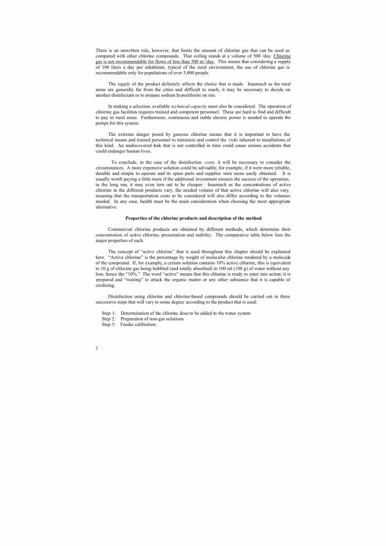
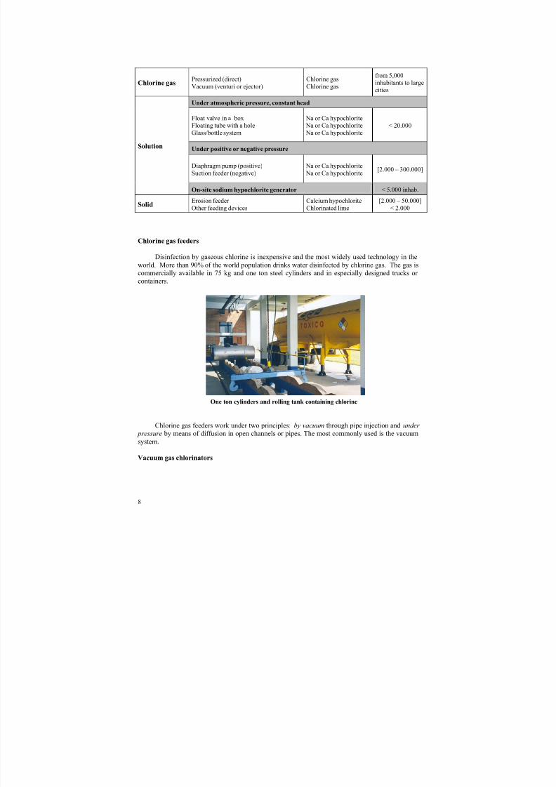
Disinfection by gaseous chlorine is inexpensive and the most widely used technology in the
world. More than 90% of the world population drinks water disinfected by chlorine gas. The gas is
commercially available in 75 kg and one ton steel cylinders and in especially designed trucks or
containers.
One ton cylinders and rolling tank containing chlorine
Chlorine gas feeders work under two principles: by vacuum through pipe injection and under
pressure by means of diffusion in open channels or pipes. The most commonly used is the vacuum
system.
Vacuum gas chlorinators
8/4/2019 Chapter3 Chlorine
http://slidepdf.com/reader/full/chapter3-chlorine 10/35
9
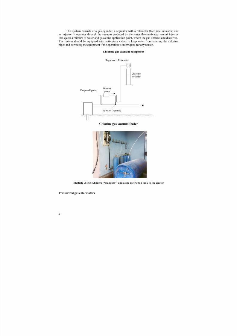
This system consists of a gas cylinder, a regulator with a rotameter (feed rate indicator) and
an injector. It operates through the vacuum produced by the water flow-activated venturi injector
that ejects a mixture of water and gas at the application point, where the gas diffuses and dissolves.
The system should be equipped with anti-return valves to keep water from entering the chlorine pipes and corroding the equipment if the operation is interrupted for any reason.
Chlorine gas vacuum equipment
Chlorine gas vacuum feeder
Multiple 75 Kg cylinders (“manifold”) and a one metric ton tank to the ejector
Pressurized gas chlorinators
Deep well pumpBooster
pump
Chlorine
cylinder
Injector (venturi)
Regulator + Rotameter
8/4/2019 Chapter3 Chlorine
http://slidepdf.com/reader/full/chapter3-chlorine 11/35
10
Chlorinecylinder
Canal de
Feeding channel
Diffuser
Regulator + Rotameter
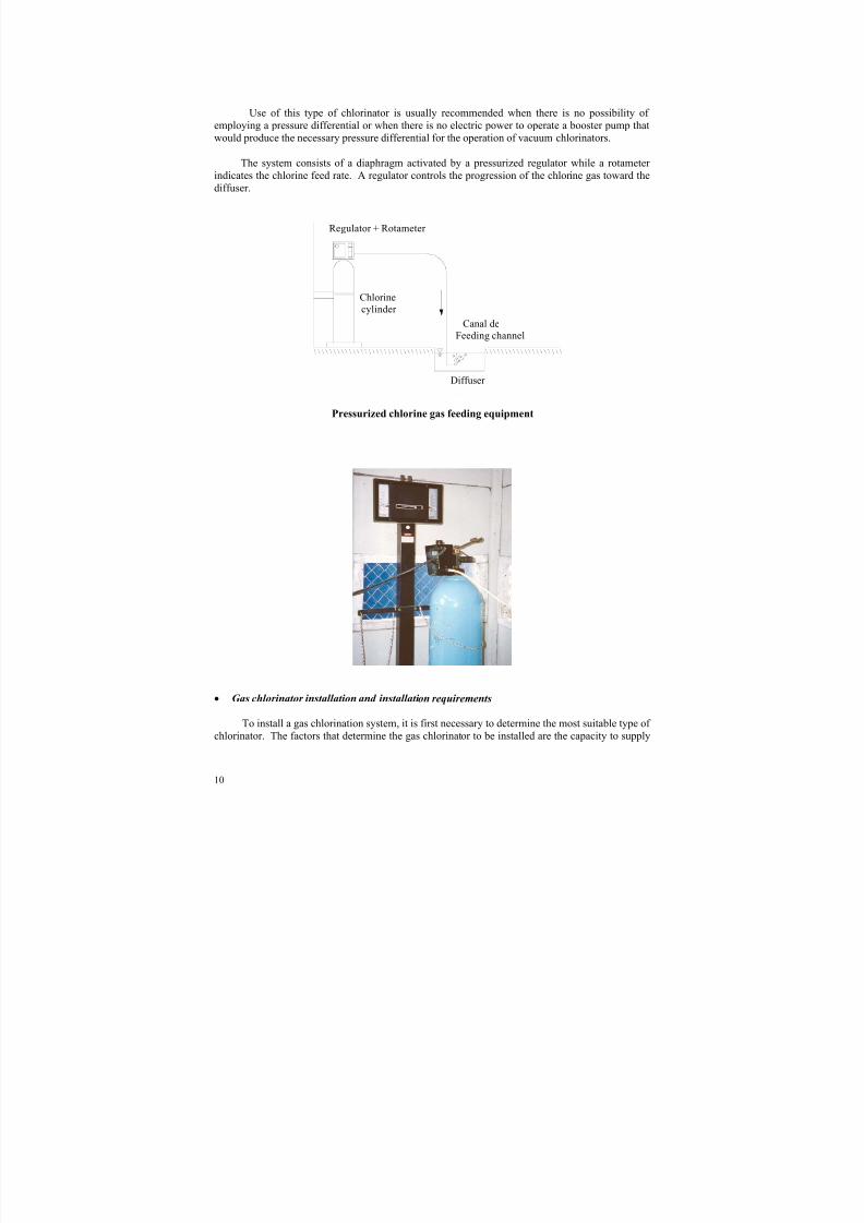
Use of this type of chlorinator is usually recommended when there is no possibility of
employing a pressure differential or when there is no electric power to operate a booster pump that
would produce the necessary pressure differential for the operation of vacuum chlorinators.
The system consists of a diaphragm activated by a pressurized regulator while a rotameter
indicates the chlorine feed rate. A regulator controls the progression of the chlorine gas toward the
diffuser.
Pressurized chlorine gas feeding equipment
• Gas chlorinator installation and installation requirements
To install a gas chlorination system, it is first necessary to determine the most suitable type of
chlorinator. The factors that determine the gas chlorinator to be installed are the capacity to supply
8/4/2019 Chapter3 Chlorine
http://slidepdf.com/reader/full/chapter3-chlorine 12/35
11
the necessary amount of chlorine per unit of time (kg/h) and the operational flexibility. The
equation for making this calculation was explained above with reference to chlorinator calibration.
Converted appropriately, the equation stands as follows:
M = 3.6 D x Q
Where:
M (gCl/h) = Amount of chlorine to be injected
D (mgCl/l) = Chlorine dose
Q (l/s) = Maximum water flow to be treated.
The typical feeding rates for the smallest vacuum chlorinators range from approximately 10
to 100 g/h. The most common devices have maximum operating capacities of 2 kg/h, 5 kg/h and 10
kg/h, making it possible to serve medium-sized to large cities.
The smallest pressurized chlorinators have a capacity of between 10 y 150 g/h. A simplecalculation reveals that if 1 mgCl/liter is added to the water for disinfection purposes and if the
population’s daily water use is 100 liters/inhabitant x day, a dose of 100 g chlorine/h could disinfect
the drinking water for a population of 24,000 inhabitants and 1 kg chlorine/h, for a population of 240,000 people.
The maximum continuous feeding rate must be calculated according to the lowest
environmental temperature forecast because the pressure of the chlorine gas in the cylinder varies
according to that temperature. The environmental temperature must be above –5 °C for a
continuous chlorine gas feeding rate of 120 g/h.
As for the installation requirements and precautions, since the most precise way to determine
the effective chlorine gas feeding rate being dosed is by measuring the weight of the chlorineconsumed, appropriate scales must be used. Correct weighing will make it possible to calculate the
exact amount of chlorine being dosed over a given period of time and also when and how soon the
cylinders should be replaced. The scales for small water supply systems are designed for use with
45 or 70 kg cylinders in an upright position. All chlorine gas installations must be equipped with
chains or other anchoring devices well attached to a wall to keep the chlorine cylinders from being
accidentally tipped over.
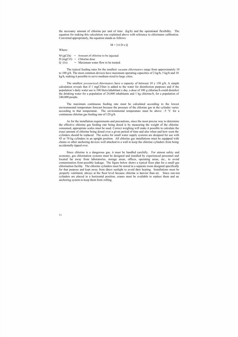
Since chlorine is a dangerous gas, it must be handled carefully. For utmost safety and
economy, gas chlorination systems must be designed and installed by experienced personnel and
located far away from laboratories, storage areas, offices, operating areas, etc., to avoid
contamination from possible leakage. The figure below shows a typical floor plan for a small gas
chlorination facility. The chlorine cylinders must be stored in a separate room designed specificallyfor that purpose and kept away from direct sunlight to avoid their heating. Installations must be
properly ventilated, always at the floor level because chlorine is heavier than air. Since one-ton
cylinders are placed in a horizontal position, cranes must be available to replace them and an
anchoring system to keep them from rolling.
8/4/2019 Chapter3 Chlorine
http://slidepdf.com/reader/full/chapter3-chlorine 13/35
12
In the case of pressurized chlorination systems, it is important for the contact chamber,
whether channel or tank, to be designed to carry a minimum water head of 0.5 meters over the
diffuser to ensure that all of the chlorine gas is dissolved and avoid its loss in the air. Since the pressure of the chlorine gas in the cylinder itself activates this type of chlorinator, there is no need
for external electric power. This is an advantage when there is no source of hydraulic or electric
power to produce the pressure differential required by a vacuum chlorinator.
Relatively little electric power is needed to operate vacuum chlorinators, only enough to
introduce the water flow through the ejector (venturi). The needed water flow and differential
pressure can be produced by electric or hydraulic means with the aid of a small 1 to 1.5 HP
auxiliary (booster) pump. In choosing electrically-operated equipment, the reliability and stability
of the power source is an important consideration.
In both systems, as a safety measure, a manual pressure relief valve is inserted between the
chlorinator and the diffuser to discharge (outside the building) any remaining chlorine gas whencylinders are replaced. In this connection, all large treatment plants must always have a leak
detection system and a stock of chlorine neutralizing products on hand.
Care must be taken with the materials used in chlorination equipment because they react
differently to oxidation. The following table shows the resistance of some of the most common
materials.
Resistance of some materials to different forms of chlorineSolid steel Stainless steel Copper PVC Teflon (PTFE)
Dry gaseous
chlorine
Good up to
120 °C
Good up to 150 °C Good up to
200 °C
Good up to
40 °C
Good up to
200 °C
Chlorine cylinders
Empty
cylinders
Booster pump
Scale
Ventilation at ceiling
level
Cart
Fixed vent at
floor level
Fixed vent at
floor level
Leak detector
Leak detector
Doors equipped
with safety locking device
External light and fan switches
Typical floor plan for a small gas chlorination facility
8/4/2019 Chapter3 Chlorine
http://slidepdf.com/reader/full/chapter3-chlorine 14/35
13
Moist
gaseous
chlorine
Nil Nil Nil Good up to40 °C
Good up to200 °C
Liquidchlorine Good Good Good Nil Acceptable
• Operation and maintenance of gas chlorinators
Vacuum chlorinators need to be regularly inspected and maintained by trained operators.
The manufacturer’s instructions must be followed to ensure that they operate properly and to avoid
costly repairs and accidents. This type of system is generally long-lasting and relatively free from
problems. Extreme care must be taken to keep moisture out of the gaseous chlorine in the feeding
system, for moist chlorine gas will rapidly corrode or destroy the equipment: the plastic parts, metal
fittings, valves, flexible connections, etc. The materials used in the chlorination system, including
spare parts and accessories, must be appropriate for the handling of moist and dry gaseous chlorine.Ferric chloride scaling on the pipes, generally due to impurities in the chlorine, must be removed
regularly. An appropriate quantity of spare parts must be available at all times. Flexible
connections must be replaced as recommended by the manufacturer. Lead gaskets between the
cylinder and the chlorinator should be used only once. When the joints between cylinder andchlorinator must be opened to replace cylinders, or for any other reason, the gaskets must be
replaced by new ones recommended by the manufacturer. The reuse of used gaskets is probably the
most common cause of chlorine gas leakage.
The same care must be taken with pressurized chlorination equipment. It is also necessary
to keep in mind that a counter pressure of more than 10 m of water column will cause problems in
the diffusion of the chlorine in the pipes; in that case, vacuum-type chlorinators should be chosen.
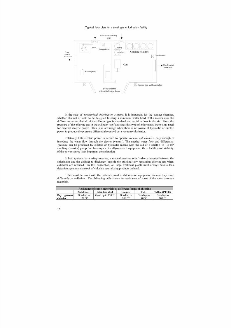
It is common practice for an operator to check and, if necessary, adjust the chlorine gas dose
three or four times during an eight-hour shift. Care should be taken not to extract more than 18 kg
of chlorine gas a day from a single cylinder; more
will result in the freezing of the cylinder due to a
rapid fall in pressure, known as the “Joule-
Thompson effect.”
An experienced operator should take less than
15 minutes to routinely replace an empty cylinder
with a full one. For safety reasons, at least two
operators should be present for this operation.
Because of its extreme toxicity and corrosiveness, strict safety regulations govern the use of
gaseous chlorine. In the case of fire, the tanks or cylinders should be removed first because their
fire resistance is guaranteed only up to 88 °C (with a 30-bar internal pressure). Because steel will burn in the presence of chlorine, care must be taken not to crack the containers (by not using a
hammer to unblock or unfreeze valves). Moist chlorine is highly corrosive: a chlorine leak will
Personal safety
8/4/2019 Chapter3 Chlorine
http://slidepdf.com/reader/full/chapter3-chlorine 15/35
14
cause external corrosion and the entry of water into pipes carrying chlorine will cause them to
corrode inside.
Gas masks must be used when handling the containers in any of the areas where chlorine isstored and it should be recalled that masks with carbon filters have a limited service life.
Hypochlorite feeders operated under atmospheric pressure
All chorine-based products, except for chlorine gas, are liquid or, if solid, can be dissolved
and used as a solution. Hypochlorite disinfection is the most popular method used in rural areas. It
is simple, easy and inexpensive and there are many available devices using the appropriate
technology.
There are several ways to feed a solution and dosers can be classified according to their
driving force, which can be of two kinds: atmospheric pressure and positive or negative pressure.
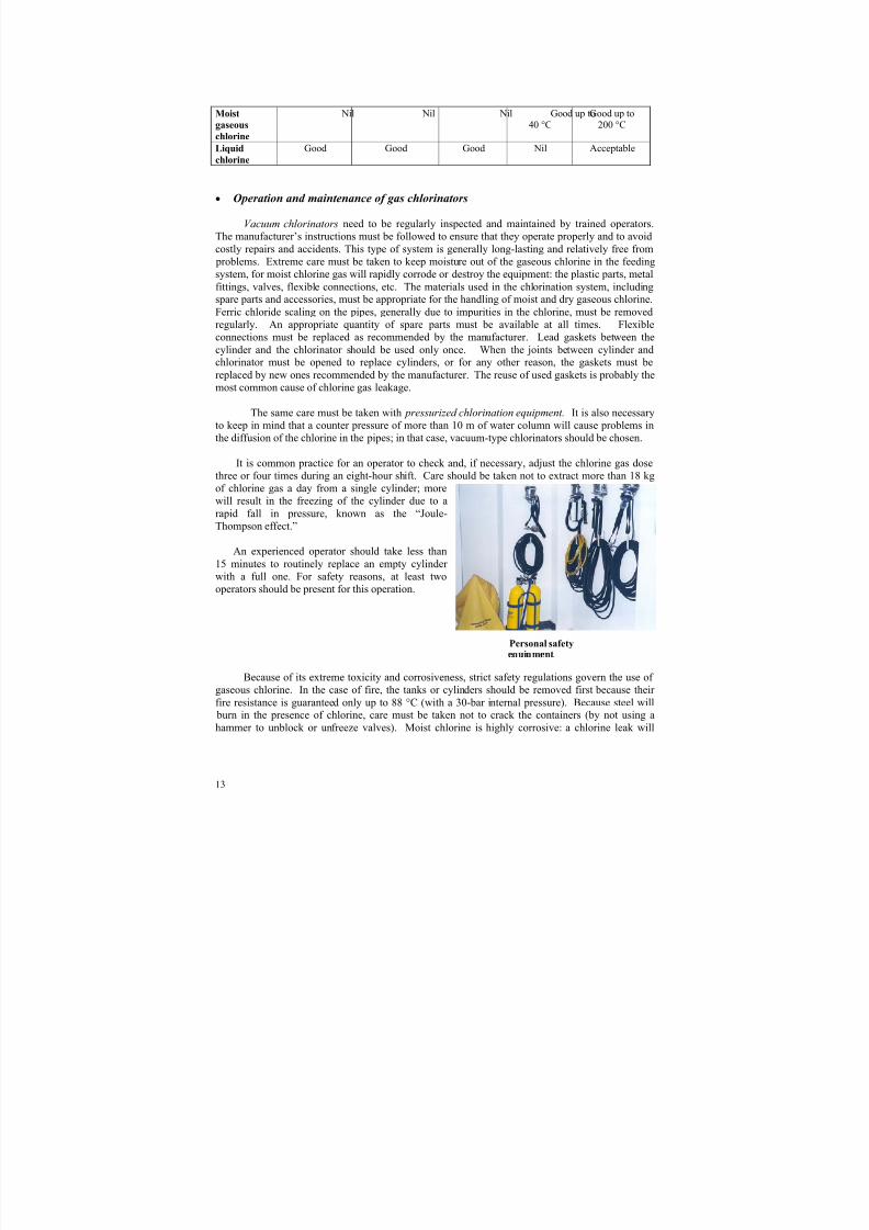
Some of the devices that work under atmospheric pressure have been designed with a
varying head, such as the paddle wheel feeder or the Archimedes wheel .
Paddle wheel feeder Archimedes wheel
The most popular devices, however, are those that operate under the “constant head”
principle, which are more precise and reliable. A constant head system is composed of two
elements: a constant head tank of a stock solution to be fed and a regulating mechanism. Three of
the most recommended systems are shown, perhaps the most popular of which is the floating tube
with a hole that is used in many countries. All three systems can be built from materials that areeasily obtained locally.
to application pointwheel
channel
holes
solution
paddle
tank with constant head
stock
8/4/2019 Chapter3 Chlorine
http://slidepdf.com/reader/full/chapter3-chlorine 16/35
15
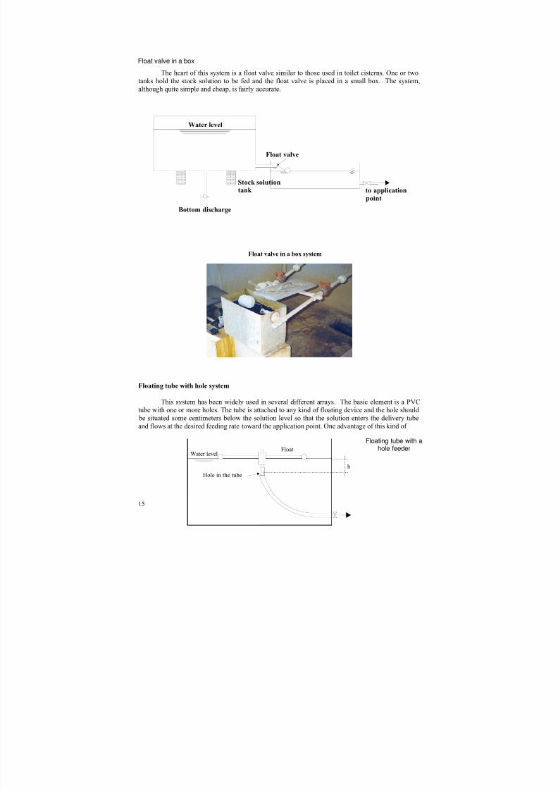
The heart of this system is a float valve similar to those used in toilet cisterns. One or two
tanks hold the stock solution to be fed and the float valve is placed in a small box. The system,
although quite simple and cheap, is fairly accurate.
Floating tube with hole system
This system has been widely used in several different arrays. The basic element is a PVC
tube with one or more holes. The tube is attached to any kind of floating device and the hole should
be situated some centimeters below the solution level so that the solution enters the delivery tube
and flows at the desired feeding rate toward the application point. One advantage of this kind of
Water level
Float valve
Stock solution
tank
Bottom discharge
to application
point
Hole in the tube
FloatWater level
h
Float valve in a box system
Float valve in a box
Floating tube with a hole feeder
8/4/2019 Chapter3 Chlorine
http://slidepdf.com/reader/full/chapter3-chlorine 17/35
16
hypochlorinator is that it does not corrode because it is made of plastic piping. Furthermore, thereare no valves to break down and the obstructions produced by calcium or magnesium scaling is
easily removed. The feeding rate can be easily adjusted merely by changing the depth of the holes.
When properly designed, installed and maintained, this kind of chlorinator has proven to be exact
and reliable.
• Installation and installation requirements
These systems should be built of materials that are resistant to the corrosion caused by astrong hypochlorite solution. The solution tank can be made of high-density polyethylene (PEHD),
fiberglass or asbestos-cement. The floater can be PVC or wood. No aluminum, steel, copper or
stainless steel should be used because they are rapidly destroyed.
This device, like all constant head systems, is easy to install. Its application is limited to
cases where the hypochlorite solution can flow by gravity toward the mixing site, whether channel
or chlorine contact chamber, or directly toward a storage tank. The installation should include an
airspace in the discharge pipe to avoid possible siphoning. The system should also be designed in
such a way that there is no chance of having the contents of the solution tank discharge all at once
accidentally into the mixture channel or the contact chamber if an accessory or pipe is broken or
any other type of spill occurs. The installation design should facilitate handling of the chlorine
compounds and solution mixtures and adjustment of the dosing. A water faucet should be located
conveniently for use in preparing stock solutions and for general hygiene.
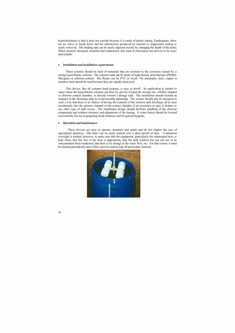
• Operation and maintenance
These devices are easy to operate, maintain and repair and do not require the care of
specialized operators. The latter can be easily trained over a short period of time. Continuous
oversight is needed, however, to make sure that the equipment, particularly the submerged hole, is
kept clean, that the size of the dose is appropriate, that the tank solution has not run out or its
concentration been weakened, that there is no change in the water flow, etc. For that reason, it must
be cleaned periodically and a filter must be used to trap all particulate material.
8/4/2019 Chapter3 Chlorine
http://slidepdf.com/reader/full/chapter3-chlorine 18/35
17
Great care must be taken when preparing the hypochlorite solution by hand, as explained
earlier. When using calcium hypochlorite, the concentration of the solution must be between 1%
and 3% available chlorine to impede the excessive formation of calcium scaling and sediments.
Sodium hypochlorite solutions can have a 10% concentration. Higher concentrations are notadvisable because they lose their strength rapidly and if too high they can crystallize.
Bottle/glass system
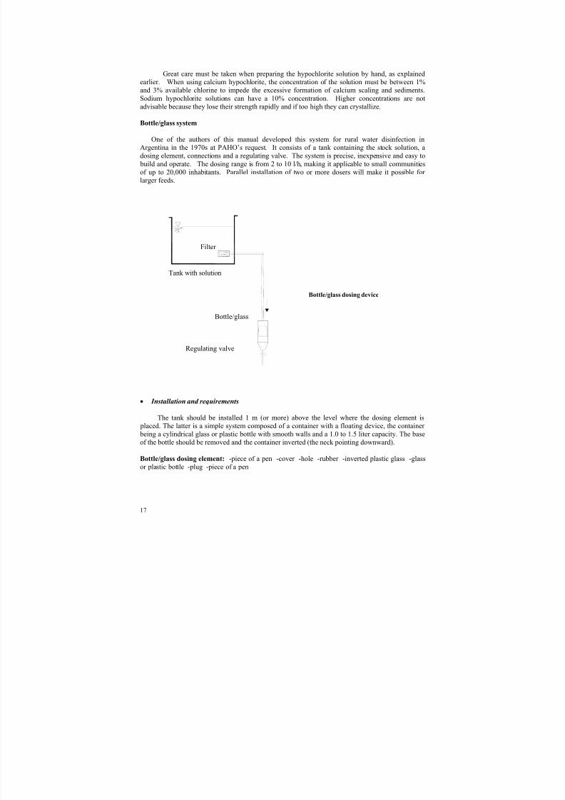
One of the authors of this manual developed this system for rural water disinfection in
Argentina in the 1970s at PAHO’s request. It consists of a tank containing the stock solution, a
dosing element, connections and a regulating valve. The system is precise, inexpensive and easy to
build and operate. The dosing range is from 2 to 10 l/h, making it applicable to small communities
of up to 20,000 inhabitants. Parallel installation of two or more dosers will make it possible for
larger feeds.
Bottle/glass dosing device
• Installation and requirements
The tank should be installed 1 m (or more) above the level where the dosing element is
placed. The latter is a simple system composed of a container with a floating device, the container
being a cylindrical glass or plastic bottle with smooth walls and a 1.0 to 1.5 liter capacity. The base
of the bottle should be removed and the container inverted (the neck pointing downward).
Bottle/glass dosing element: -piece of a pen -cover -hole -rubber -inverted plastic glass -glass
or plastic bottle -plug -piece of a pen
Tank with solution
Filter
Bottle/glass
Regulating valve
8/4/2019 Chapter3 Chlorine
http://slidepdf.com/reader/full/chapter3-chlorine 19/35
18
A small cover made of wood or plastic is glued to the upper part (area of the removed base)
of the device using epoxy glue. This cover has two holes: a central hole, where another ¼” plastic
tube or a piece of pen is introduced (without any ink cartridge) and left protruding approximately 1
cm. This tube should be firmly welded or glued to the cover and its borders should be leveled andsmoothed. The second hole allows the air to flow freely.
The floating device is a plastic glass or jar, with or without a top, placed upside down (with
the mouth facing downward) inside the bottle. A piece of soft rubber is glued to the outside of the
base. With the air trapped inside, the jar or the plastic glass will operate as a floating device. The
flow is regulated using a simple locally manufactured valve.
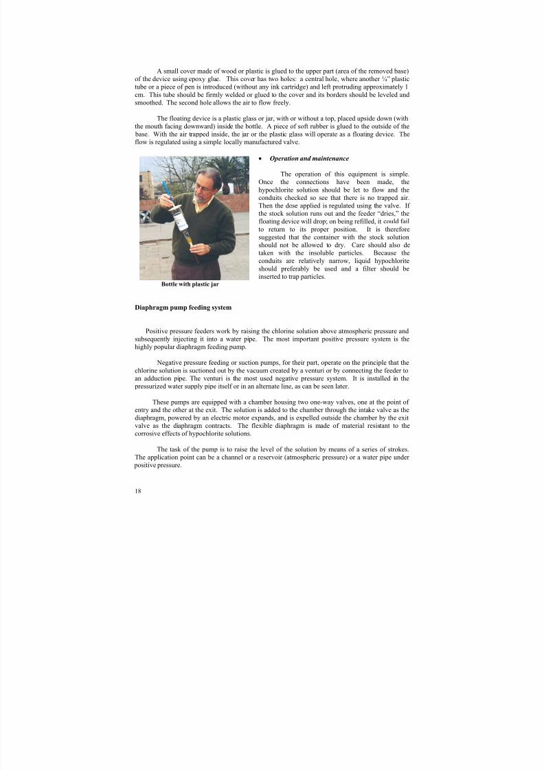
• Operation and maintenance
The operation of this equipment is simple.
Once the connections have been made, the
hypochlorite solution should be let to flow and theconduits checked so see that there is no trapped air.
Then the dose applied is regulated using the valve. If
the stock solution runs out and the feeder “dries,” the
floating device will drop; on being refilled, it could fail
to return to its proper position. It is therefore
suggested that the container with the stock solution
should not be allowed to dry. Care should also de
taken with the insoluble particles. Because the
conduits are relatively narrow, liquid hypochlorite
should preferably be used and a filter should be
inserted to trap particles.
Bottle with plastic jar
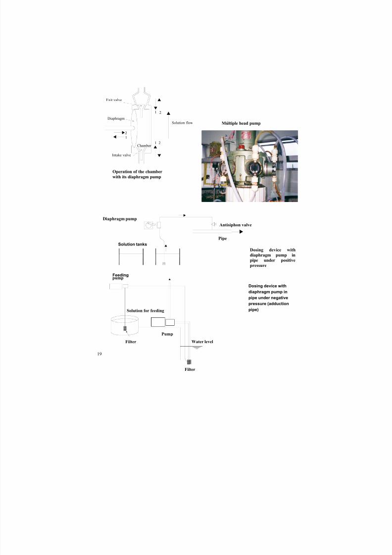
Diaphragm pump feeding system
Positive pressure feeders work by raising the chlorine solution above atmospheric pressure and
subsequently injecting it into a water pipe. The most important positive pressure system is the
highly popular diaphragm feeding pump.
Negative pressure feeding or suction pumps, for their part, operate on the principle that the
chlorine solution is suctioned out by the vacuum created by a venturi or by connecting the feeder to
an adduction pipe. The venturi is the most used negative pressure system. It is installed in the pressurized water supply pipe itself or in an alternate line, as can be seen later.
These pumps are equipped with a chamber housing two one-way valves, one at the point of
entry and the other at the exit. The solution is added to the chamber through the intake valve as the
diaphragm, powered by an electric motor expands, and is expelled outside the chamber by the exit
valve as the diaphragm contracts. The flexible diaphragm is made of material resistant to the
corrosive effects of hypochlorite solutions.
The task of the pump is to raise the level of the solution by means of a series of strokes.
The application point can be a channel or a reservoir (atmospheric pressure) or a water pipe under
positive pressure.
8/4/2019 Chapter3 Chlorine
http://slidepdf.com/reader/full/chapter3-chlorine 20/35
19
Dosing device with
diaphragm pump in
pipe under positive
pressure
Solution flow
1
1 2
2
2
1
Exit valve
Intake valve
Diaphragm
Chamber
Diaphragm pump
Pipe
Tanques de solución
Antisiphon valve
Filter
Solution for feeding
pump
Pump
Water level
Filter
Múltiple head pump
Operation of the chamber
with its diaphragm pump
Solution tanks
Dosing device with
diaphragm pump in
pipe under negative
pressure (adduction
pipe)
Feeding
8/4/2019 Chapter3 Chlorine
http://slidepdf.com/reader/full/chapter3-chlorine 21/35
20
This type of hypochlorinator has a large capacity; the smallest device supplies nearly one liter of hypochlorite/hour and the largest almost 200 liters/hour. A widely varying water flow can be
disinfected, depending upon the concentration of the solution and the desired dose of chlorine.
• Installation and installation requirements
Diaphragm pumps are usually powered by electric motors; hydraulically-powered pumps are
less common. The latter can be used when there is no reliable source of electric power. An
advantage of this system is that the hypochlorite feeding speed can be calibrated to the water flow
speed by using a special device. A disadvantage of using hydraulic power is its mechanical
complexity, which often causes operating and maintenance problems. Relatively little power,generally from ¼ to ¾ HP, is needed to operate the hypochlorinator. In choosing this type of
chlorinator, it is important to consider the reliability and quality of the power source to be used.
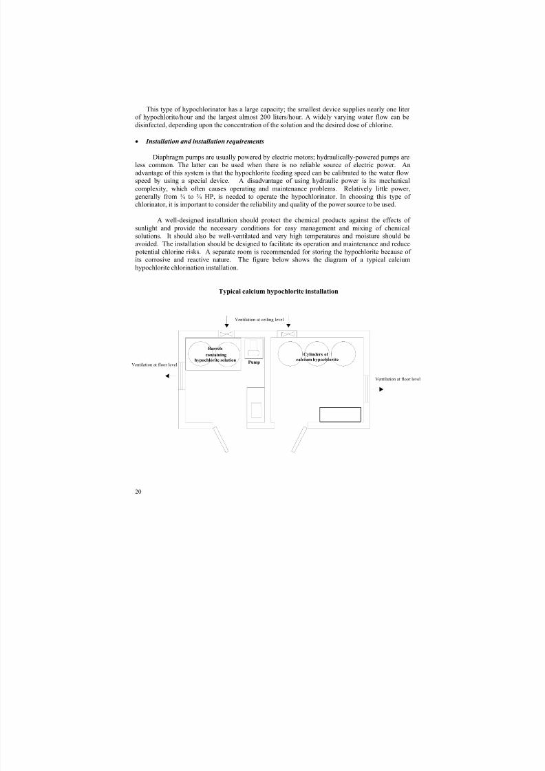
A well-designed installation should protect the chemical products against the effects of
sunlight and provide the necessary conditions for easy management and mixing of chemical
solutions. It should also be well-ventilated and very high temperatures and moisture should be
avoided. The installation should be designed to facilitate its operation and maintenance and reduce
potential chlorine risks. A separate room is recommended for storing the hypochlorite because of
its corrosive and reactive nature. The figure below shows the diagram of a typical calcium
hypochlorite chlorination installation.
Typical calcium hypochlorite installation
Cylinders of
calcium hypochloritePump
Barrels
containinghypochlorite solution
Ventilation at ceiling level
Ventilation at floor level
Ventilation at floor level
8/4/2019 Chapter3 Chlorine
http://slidepdf.com/reader/full/chapter3-chlorine 22/35
21
• Operation and maintenance
The capacity of diaphragm pumps can be regulated to adjust the hypochlorite solution feed
by adjusting either the frequency or length of the pump stroke. Most hypochlorinators use variable
speed motors to regulate the frequency or length of the pump stroke. Some employ mechanical
means to adjust its length and a few make use of both methods. Control of the pump stroke
frequency appears to be the method of choice of most small water supply systems because of its
simplicity. Starting and stopping, as well as the feed rate, tend to be controlled manually, although
starting and stopping can also be controlled automatically using a magnetic switch connected
directly to the water pump regulator. Complicated control systems that adjust the feed rate
automatically are not generally recommended for use by small communities.
Chlorinators of this kind are simple to operate and maintain, but do require continuous andappropriate maintenance. The feed can be exact and uniform if the equipment valves are kept free
from precipitates and scaling. A concentration of 1 to 3% is recommended for calcium hypochlorite
solutions in order to reach an economic balance between the costs of pumping and of preventing
calcium precipitation in the check valves and diaphragm chamber. Special care must be takenwhen the water is hard, containing high contents of dissolved solids, or when using dissolved
chlorinated lime. The use of sodium hypochlorite solutions with a concentration of less than 10% is
recommended in order to avoid precipitates and maintain the stability of the chlorine.
Because the diaphragm pump is made up of metal pieces, these can corrode and reduce its
service life. For that reason, the pump must be replaced periodically. The check valves are exposed
to calcium scaling and so must be cleaned with an acid solution to avoid their deficient operation or
having to replace them more frequently due to a loss of elasticity as a result of oxidation.Hypochlorite solutions must also be handled with care. Inasmuch as they are highly corrosive, the
tools and containers used to prepare them must be made of plastic or ceramic or other corrosion-
resistant materials. Personnel must be trained to handle spills and in the correct equipment
operation and maintenance procedures.
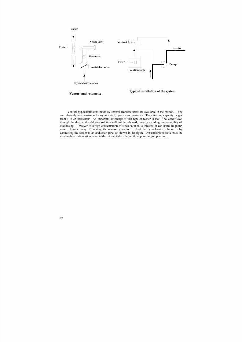
Suction feeders (venturi-type)
The suction feeder in widest use employs a venturi device that makes it possible to feed
chlorinated solutions through pressurized pipes. This type of chlorinator is based on the same
principle as that of the ejector used in gas chlorinators. The vacuum created by the water flow
through the venturi pipe suctions the hypochlorite solution and discharges it directly into the mainwater stream or a secondary one. The feed is regulated by adjusting a needle valve installed
between the venturi device and the rotameter.
Agua
Venturi
Rotámetro
Válvulaanti-sifón
Vávula deaguja Alimentador
Venturi
Tanque de
solución
BombaFiltro
8/4/2019 Chapter3 Chlorine
http://slidepdf.com/reader/full/chapter3-chlorine 23/35
22
Venturi y rotámetro
Venturi hypochlorinators made by several manufacturers are available in the market. Theyare relatively inexpensive and easy to install, operate and maintain. Their feeding capacity rangesfrom 1 to 25 liters/hour. An important advantage of this type of feeder is that if no water flowsthrough the device, the chlorine solution will not be released, thereby avoiding the possibility of
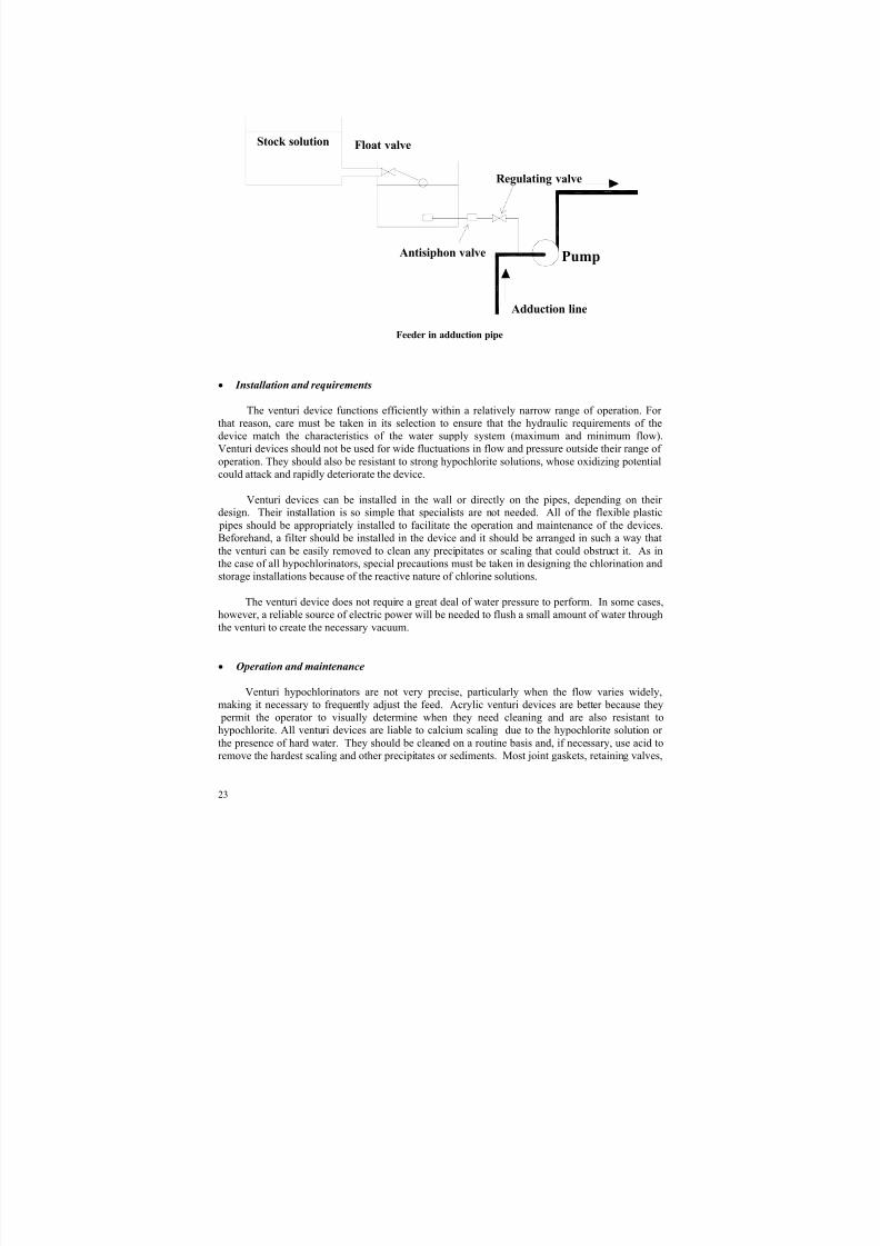
overdosing. However, if a high concentration of stock solution is injected, it can harm the pumprotor. Another way of creating the necessary suction to feed the hypochlorite solution is byconnecting the feeder to an adduction pipe, as shown in the figure. An antisiphon valve must beused in this configuration to avoid the return of the solution if the pump stops operating.
Water
Venturi
Rotameter
Antisiphon valve
Needle valve
Hypochlorite solution
Venturi feeder
Solution tank
PumpFilter
Venturi and rotameteTypical installation of the system
8/4/2019 Chapter3 Chlorine
http://slidepdf.com/reader/full/chapter3-chlorine 24/35
23
Pump
Stock solution Float valve
Adduction line
Regulating valve
Antisiphon valve
Feeder in adduction pipe
• Installation and requirements
The venturi device functions efficiently within a relatively narrow range of operation. For that reason, care must be taken in its selection to ensure that the hydraulic requirements of thedevice match the characteristics of the water supply system (maximum and minimum flow).Venturi devices should not be used for wide fluctuations in flow and pressure outside their range of
operation. They should also be resistant to strong hypochlorite solutions, whose oxidizing potentialcould attack and rapidly deteriorate the device.
Venturi devices can be installed in the wall or directly on the pipes, depending on their design. Their installation is so simple that specialists are not needed. All of the flexible plastic pipes should be appropriately installed to facilitate the operation and maintenance of the devices.Beforehand, a filter should be installed in the device and it should be arranged in such a way thatthe venturi can be easily removed to clean any precipitates or scaling that could obstruct it. As inthe case of all hypochlorinators, special precautions must be taken in designing the chlorination andstorage installations because of the reactive nature of chlorine solutions.
The venturi device does not require a great deal of water pressure to perform. In some cases,
however, a reliable source of electric power will be needed to flush a small amount of water throughthe venturi to create the necessary vacuum.
• Operation and maintenance
Venturi hypochlorinators are not very precise, particularly when the flow varies widely,making it necessary to frequently adjust the feed. Acrylic venturi devices are better because they permit the operator to visually determine when they need cleaning and are also resistant tohypochlorite. All venturi devices are liable to calcium scaling due to the hypochlorite solution or the presence of hard water. They should be cleaned on a routine basis and, if necessary, use acid toremove the hardest scaling and other precipitates or sediments. Most joint gaskets, retaining valves,
8/4/2019 Chapter3 Chlorine
http://slidepdf.com/reader/full/chapter3-chlorine 25/35
24
springs and joints deteriorate over time because of being in contact with hypochlorite; they should,therefore, be replaced periodically. These spare parts should be made of proper materials and be onhand at all times.
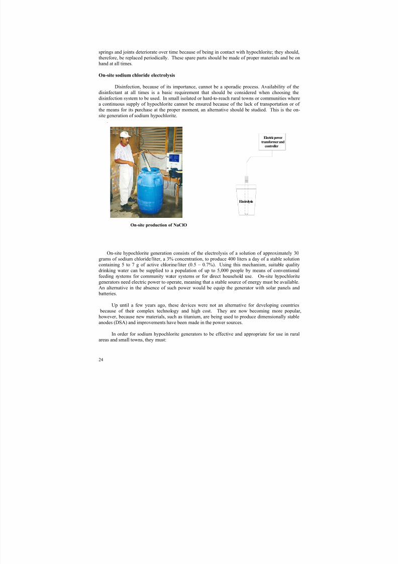
On-site sodium chloride electrolysis
Disinfection, because of its importance, cannot be a sporadic process. Availability of thedisinfectant at all times is a basic requirement that should be considered when choosing thedisinfection system to be used. In small isolated or hard-to-reach rural towns or communities wherea continuous supply of hypochlorite cannot be ensured because of the lack of transportation or of the means for its purchase at the proper moment, an alternative should be studied. This is the on-site generation of sodium hypochlorite.
.
On-site production of NaClO
On-site hypochlorite generation consists of the electrolysis of a solution of approximately 30grams of sodium chloride/liter, a 3% concentration, to produce 400 liters a day of a stable solutioncontaining 5 to 7 g of active chlorine/liter (0.5 – 0.7%). Using this mechanism, suitable qualitydrinking water can be supplied to a population of up to 5,000 people by means of conventionalfeeding systems for community water systems or for direct household use. On-site hypochloritegenerators need electric power to operate, meaning that a stable source of energy must be available.An alternative in the absence of such power would be equip the generator with solar panels and batteries.
Up until a few years ago, these devices were not an alternative for developing countries because of their complex technology and high cost. They are now becoming more popular,however, because new materials, such as titanium, are being used to produce dimensionally stableanodes (DSA) and improvements have been made in the power sources.
In order for sodium hypochlorite generators to be effective and appropriate for use in ruralareas and small towns, they must:
Electrolysis
Electric powertransformer andcontroller
8/4/2019 Chapter3 Chlorine
http://slidepdf.com/reader/full/chapter3-chlorine 26/35
25
• be inexpensive;
• be easy to operate and maintain;
• be reliable and durable, offering uniform production;• be able to use locally available table salt (sodium chloride), and
• have a production capacity of between 0.5 and 2.0 kg of chlorine every 24 hours.
Commercial devices have been developed in several countries and PAHO/CEPIS has madetechnical evaluations of the most widely used. The characteristics and requirements of the water supply system in question should govern the application of these systems.
• Installation and requirements
The system includes dissolution tanks. A reserve of salt must also be stored, requiringadditional space. Although the devices for producing NaOCl are easily installed, precautions must
be taken to separate them from the components that are susceptible to corrosion, such as theelectrical controls, motors, pumps, regulators and other metal equipment, because the area adjacentto the production units tends to be highly corrosive. The installations must be designed in such away that they facilitate the handling of the salt and the transfer of the hypochlorite solution fromone tank to another and to the application site. The premises should be well-ventilated.
The efficiency of sodium hypochlorite production varies slightly according to the differenttypes of device. Experience has shown that 6 to 10 kilowatts/hour of electric power are needed to produce one kilogram of available chlorine. This small amount of power can be obtained from avariety of sources, such as solar cells, windmill or hydraulic energy-powered electric generators,etc. Irrespective of the choice made, the source of energy must be reliable. An advantage of theon-site sodium hypochlorite production system is that it can operate during the hours when there is
electricity and store the hypochlorite for use when there is none.
These devices are very safe because they produce sodium hypochlorite solutions with a lowconcentration in relatively small amounts and most of these solutions are used immediately or within a very short period of time. Even though the procedure is low-risk, care must be taken,especially when opening the electrolytic cell, because of the possibility of a gaseous chlorine build-up. The precautions cited for the use of sodium hypochlorite should be followed in general.
• Operation and maintenance
This type of device is reliable if it is made from materials that are resistant to the highlycorrosive properties of the chemical products that are to be used and produced. Maintenance should
be carried out at regular intervals in accordance with the specifications. A problem that can arisewith certain types of devices is electrode scaling due to the presence of calcium and magnesium inthe salt. The scaling can be reduced by using refined salt and good quality dissolution water. Theuse of water softeners helps. Titanium anodes with a coating of iridium or ruthenium oxide aregenerally more lasting (between four and six years) than graphite anodes (used by some devicesinstead of titanium anodes), which last about a year. The titanium anodes can be cleaned using achlorhydric acid solution.
8/4/2019 Chapter3 Chlorine
http://slidepdf.com/reader/full/chapter3-chlorine 27/35
26
Solid calcium hypochlorite feeders
Calcium hypochlorite feeders are manufactured for large and small flows. The former are
volumetric or gravimetric feeders that drop a measured amount (in volume or weight) into a smalldissolution tank (always accompanied by mixing), where it dissolves and is later fed at theapplication point. The use of these devices is not popular, for when large flows are to be treatedchorine gas is the choice. To disinfect small flows (typical in medium-sized and smallcommunities), devices operating through tablet erosion or the direct feeding of solid calciumhypochlorite pills are preferred.
The concentration of active chlorine in these presentations is between 65 and 70%, unlike the33% concentration of powdered calcium hypochlorite, marketed under different brands. Care must be taken, however, to ensure that they are appropriate for disinfecting drinking water and that theydo not contain substances like cyanurates. Sodium cyanurates, which also release chlorine on beingdissolved in water, should only be used in emergency situations, because not enough evidence
exists about their harmlessness when used over long periods of time.
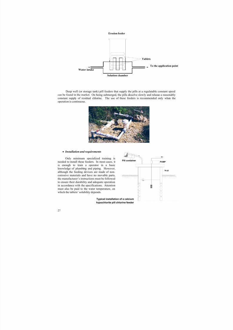
Tablet and pill erosion feeder
Erosion feeders use high concentration calcium hypochlorite tablets (HTH) that can beobtained from distributors or prepared locally by mechanically compressing powdered calciumhypochlorite. This system has found an important niche in the disinfection of water supply systemsfor small communities and households. The devices are easy to handle and maintain and are cheapand durable, as well. The tablets are safer than the hypochlorite solutions and the gaseous chlorineand are easier to handle and store.
Erosion feeders gradually dissolve hypochlorite tablets at a preset rate while a water current
flows around them. This mechanism provides the necessary chlorine dose to disinfect the water.As the tablets dissolve, they are replaced by new ones that fall into the chamber by gravity. Theconcentrated chlorine solution feeds a tank, an open channel or a reservoir, as the case may be.
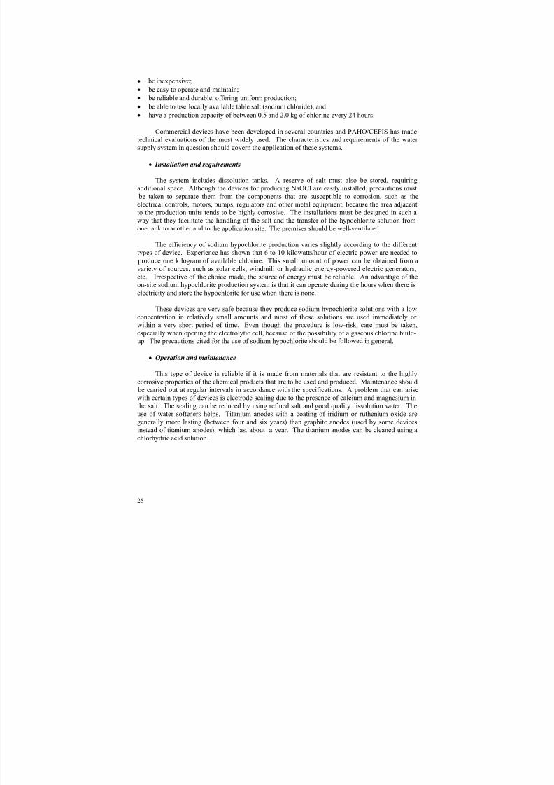
Dissolution feeders and tanks
8/4/2019 Chapter3 Chlorine
http://slidepdf.com/reader/full/chapter3-chlorine 28/35
27
Well
PUMP
Erosion feeder
Deep well (or storage tank) pill feeders that supply the pills at a regulatable constant speedcan be found in the market. On being submerged, the pills dissolve slowly and release a reasonablyconstant supply of residual chlorine. The use of these feeders is recommended only when theoperation is continuous.
• Installation and requirements
Only minimum specialized training is
needed to install these feeders. In most cases, itis enough to train a operator in a basicknowledge of plumbing and piping. However,although the feeding devices are made of non-corrosive materials and have no movable parts,the manufacturer’s instructions must be followedto ensure their durability and adequate operationin accordance with the specifications. Attentionmust also be paid to the water temperature, onwhich the tablets’ solubility depends.
Tablets
To the application point
Solution chamber
Water intake
Typical installation of a calcium
hypochlorite pill chlorine feeder
Pill container
8/4/2019 Chapter3 Chlorine
http://slidepdf.com/reader/full/chapter3-chlorine 29/35
28
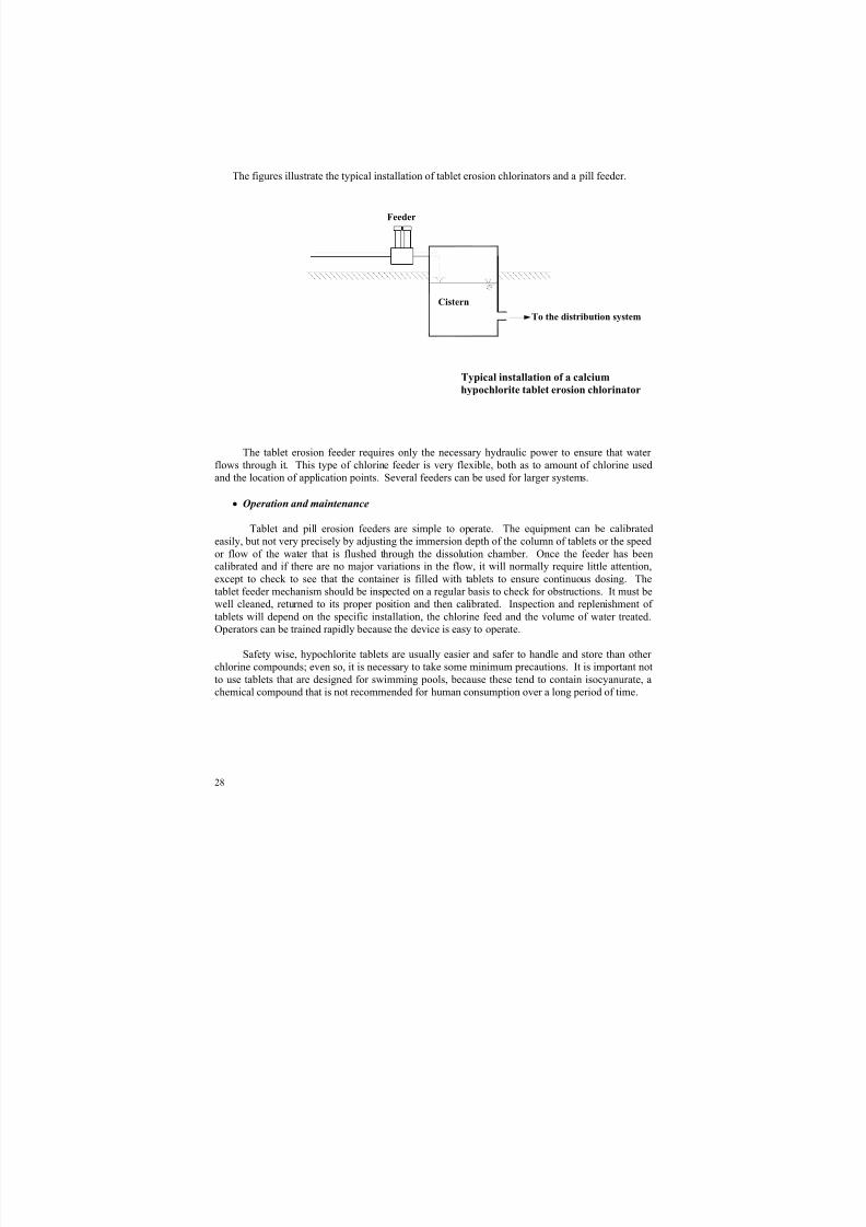
The figures illustrate the typical installation of tablet erosion chlorinators and a pill feeder.
h
Typical installation of a calcium
hypochlorite tablet erosion chlorinator
The tablet erosion feeder requires only the necessary hydraulic power to ensure that water flows through it. This type of chlorine feeder is very flexible, both as to amount of chlorine usedand the location of application points. Several feeders can be used for larger systems.
• Operation and maintenance
Tablet and pill erosion feeders are simple to operate. The equipment can be calibratedeasily, but not very precisely by adjusting the immersion depth of the column of tablets or the speedor flow of the water that is flushed through the dissolution chamber. Once the feeder has beencalibrated and if there are no major variations in the flow, it will normally require little attention,except to check to see that the container is filled with tablets to ensure continuous dosing. Thetablet feeder mechanism should be inspected on a regular basis to check for obstructions. It must be
well cleaned, returned to its proper position and then calibrated. Inspection and replenishment of tablets will depend on the specific installation, the chlorine feed and the volume of water treated.Operators can be trained rapidly because the device is easy to operate.
Safety wise, hypochlorite tablets are usually easier and safer to handle and store than other chlorine compounds; even so, it is necessary to take some minimum precautions. It is important notto use tablets that are designed for swimming pools, because these tend to contain isocyanurate, achemical compound that is not recommended for human consumption over a long period of time.
Feeder
To the distribution systemCistern

8/4/2019 Chapter3 Chlorine
http://slidepdf.com/reader/full/chapter3-chlorine 30/35
29
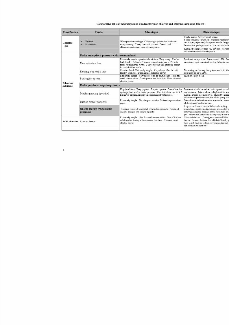
Advantages and disadvantages of the methods
The following table has been prepared to facilitate the comparison of the chlorine feeders
described.
8/4/2019 Chapter3 Chlorine
http://slidepdf.com/reader/full/chapter3-chlorine 31/35
8/4/2019 Chapter3 Chlorine
http://slidepdf.com/reader/full/chapter3-chlorine 32/35
0
Monitoring of chlorine compounds and chlorine-based products
Regular measurement of the amount of residual chlorine will make it possible to control the
operation of the feeder and the absence of contamination in the water d istribution system. For thatreason, such measurement is essential.
There are several methods for measuring residual chlorine in the water. Two of the simplestare the following:
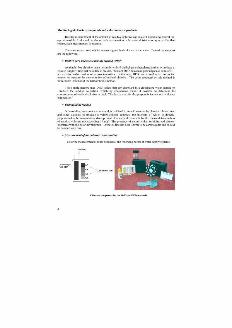
• Diethyl-para-phenylenediamine method (DPD)
Available free chlorine reacts instantly with N-diethyl-para-phenylenediamine to produce areddish tint providing that no iodine is present. Standard DPD-potassium permanganate solutionsare used to produce colors of various intensities. In this way, DPD can be used as a colorimetricmethod to measure the concentration of residual chlorine. The color produced by this method is
more stable than that of the Orthotolidine method.
This simple method uses DPD tablets that are dissolved in a chlorinated water sample to produce the reddish coloration, which by comparison makes it possible to determine theconcentration of residual chlorine in mg/l. The device used for this purpose is known as a “chlorinecomparator.”
• Orthotolidine method
Orthotolidine, an aromatic compound, is oxidized in an acid solution by chlorine, chlorazinesand other oxidants to produce a yellow-colored complex, the intensity of which is directly proportional to the amount of oxidants present. The method is suitable for the routine determination
of residual chlorine not exceeding 10 mg/l. The presence of natural color, turbidity and nitratesinterferes with the color development. Orthotolidine has been shown to be carcinogenic and should be handled with care.
• Measurement of the chlorine concentration
Chlorine measurements should be taken at the following points of water supply systems:
Chlorine comparers by the O-T and DPD methods
0,5
0,4
0,3
0,2
Test tube
Colorimetric scale
Water sample
with DPD
8/4/2019 Chapter3 Chlorine
http://slidepdf.com/reader/full/chapter3-chlorine 33/35
1
• After chlorination, at the exit of the treatment plant, to check whether the amounts of
disinfectant are correct.
It is important to bear in mind that if there is no storage reservoir for water and disinfectantmixing at the treatment plant, the contact time between the chlorine and the water may beso short that the chlorine demand is not met. In this case, the value that is obtained cansignal the presence of “active chlorine,” but in the following minutes this chlorine will beconsumed by organic matter. It is advisable, then, to wait at least 30 minutes after injectingthe chlorine in the water to measure the residual concentration of the disinfectant.
• At the tap of the consumer farthest from the treatment plant. This measurement will make it
possible to determine the presence of any contamination in the water distribution system.
These measurements should be taken several times a day every day of the year.
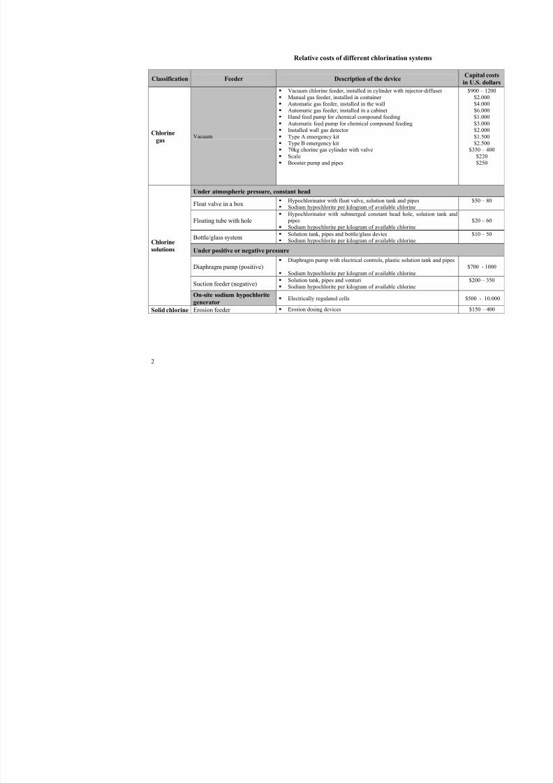
Feeder and operation and maintenance costs
The costs of the feeders will vary according to the amount and type of chemical product to beused, the type of control exercised (if needed) and the installation needs. The estimated costs of thedevices can be found in the table below.
The operating and maintenance costs vary according to the type of chemical product used andthe size and complexity of the device. Feeder manufacturers provide a list of recommended spare parts, which should be kept on hand as a minimum. Most manufacturers train treatment plant personnel in the maintenance and servicing of their equipment. Some even run exchange programsunder which that equipment is given maintenance in their facilities. This allows operating personnel to send such devices to be repaired while a replacement unit operates.
Chlorination costs are generally very low; even so, there are differences when the cost of chlorine gas is compared with that of hypochlorination. In many parts of the world, the cost of thegas is one-quarter or one-half that of an equivalent hypochlorite solution. However, the initialinvestment and installation and operational costs for a gas chlorination system are usually higher than those of hypochlorination installations, some of which cost practically nothing. This often places gaseous chlorine at an economic disadvantage in the case of very small water supplysystems.
Experience suggests the breakeven point between the costs of gas and of hypochlorination to be a dosing rate of roughly 500 to 1,000 mg of chlorine a day. The selection of gas or hypochloriteswill have to be carefully studied in the case of medium-sized communities because the advantagesand disadvantages can overlap and the choice may have to be based on additional elements. The
operator’s required skill and the community’s capacity to cover its cost are important considerationswhen making a choice. A detailed analysis of all important elements and the predominatingcircumstances is needed in each case.
8/4/2019 Chapter3 Chlorine
http://slidepdf.com/reader/full/chapter3-chlorine 34/35
2
Relative costs of different chlorination systems
Classification Feeder Description of the deviceCa
in U
Chlorine
gasVacuum
Vacuum chlorine feeder, installed in cylinder with injector-diffuser
Manual gas feeder, installed in container Automatic gas feeder, installed in the wall Automatic gas feeder, installed in a cabinet Hand feed pump for chemical compound feeding
Automatic feed pump for chemical compound feeding Installed wall gas detector
Type A emergency kit Type B emergency kit 70kg chorine gas cylinder with valve
Scale Booster pump and pipes
$
$
Under atmospheric pressure, constant head
Float valve in a box Hypochlorinator with float valve, solution tank and pipes Sodium hypochlorite per kilogram of available chlorine
Floating tube with hole Hypochlorinator with submerged constant head hole, solution tank and
pipes
Sodium hypochlorite per kilogram of available chlorine
Bottle/glass system Solution tank, pipes and bottle/glass device Sodium hypochlorite per kilogram of available chlorine
Under positive or negative pressure
Diaphragm pump (positive) Diaphragm pump with electrical controls, plastic solution tank and pipes
Sodium hypochlorite per kilogram of available chlorine$7
Suction feeder (negative) Solution tank, pipes and venturi
Sodium hypochlorite per kilogram of available chlorine
$
Chlorine
solutions
On-site sodium hypochlorite
generator Electrically regulated cells $50
Solid chlorine Erosion feeder Erosion dosing devices $
8/4/2019 Chapter3 Chlorine
http://slidepdf.com/reader/full/chapter3-chlorine 35/35
Information sources
Christman, K. Chlorine. Work presented in the PAHO Symposium: Water Quality, Effective
Disinfection (1998). Also published on CD-Rom. Available from PAHO/CEPIS.
Góngora, J. Sistemas de desinfección por medios hidráulicos para agua potable rural. Experienciacolombiana, Work presented in the CEPIS publication “Investigación sobre desinfección de agua enabastecimientos rurales” (1983).
PAHO. La desinfección del agua . PAHO/HEP/99/32 (1999) Publication.
PAHO/ILSI. La calidad del agua en América Latina. Ponderación de los riesgos microbiológicoscontra los riesgos de los subproductos de la desinfección química, ILSI Press, Washington DC(1996).
Reiff, F. Disinfection practices in developing areas. Work presented in the NSF Course on Water Disinfection in Washington DC (1998).
Reiff, F.;Witt, V. Guía para la selección y aplicación de tecnologías de desinfección del agua paraconsumo humano en pueblos pequeños y comunidades rurales en América Latina y el Caribe. PAHO/WHO Document, Technical Series No. 30 (1995).
Rojas, R., Guevara, S. Celdas electrolíticas para producción in situ de hipoclorito de sodio; CEPIS/GTZ Publicación (1999).
Solsona, F. Investigación sobre desinfección de agua para abastecimientos rurales en Argentina. Work presented in the CEPIS Publication “Investigación sobre Desinfección de agua en
abastecimientos rurales” (1983).
Solsona, F. Water disinfection for small community supplies, Chapter on water disinfection for theIRC manual “Small Community Supplies” and available as a separata from PAHO/CEPIS (2001).
Solsona, F. Disinfection for small water supplies; technical guide. CSIR Publication, South Africa(1990).
White, C. Handbook of chlorination, Van Nostrand Reinhold (1972).
WHO/WRC. Disinfection of rural and small community water supplies (1989).