Embed Size (px)
Citation preview
8/10/2019 Chapter18 Student 2
http://slidepdf.com/reader/full/chapter18-student-2 1/118
PHYSICS CHAPTER 18
1
CHAPTER 18:
Electric current and direct-
current circuits(7 Hours)
w w w . k m s
. m a t r i k . e
d u
. m y / p h y s i c s
8/10/2019 Chapter18 Student 2
http://slidepdf.com/reader/full/chapter18-student-2 2/118
PHYSICS CHAPTER 18
2
At the end of this chapter, students should be able to:
Describe microscopic model of current.
Define and use electric current formulae,
Learning Outcome:
18.1 Electrical conduction (1 hour)
w w w . k m s
. m a t r i k . e
d u
. m y / p h y s i c s
8/10/2019 Chapter18 Student 2
http://slidepdf.com/reader/full/chapter18-student-2 3/118
PHYSICS CHAPTER 18
3
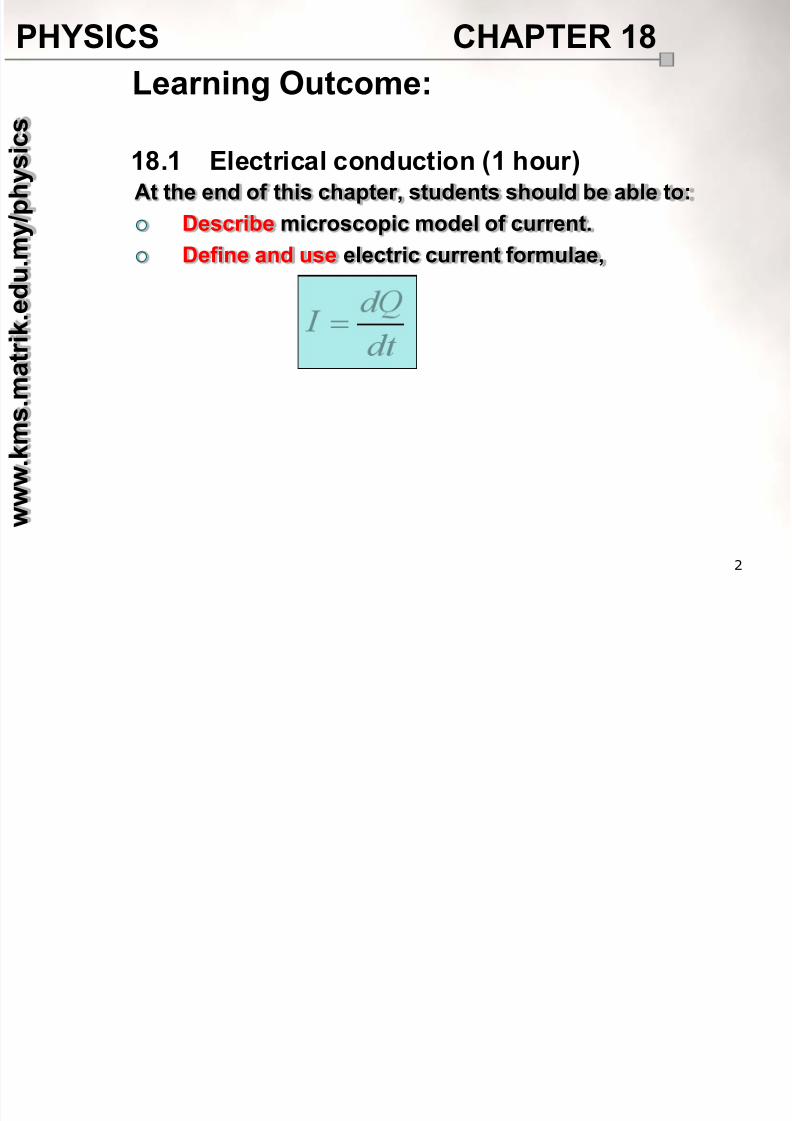
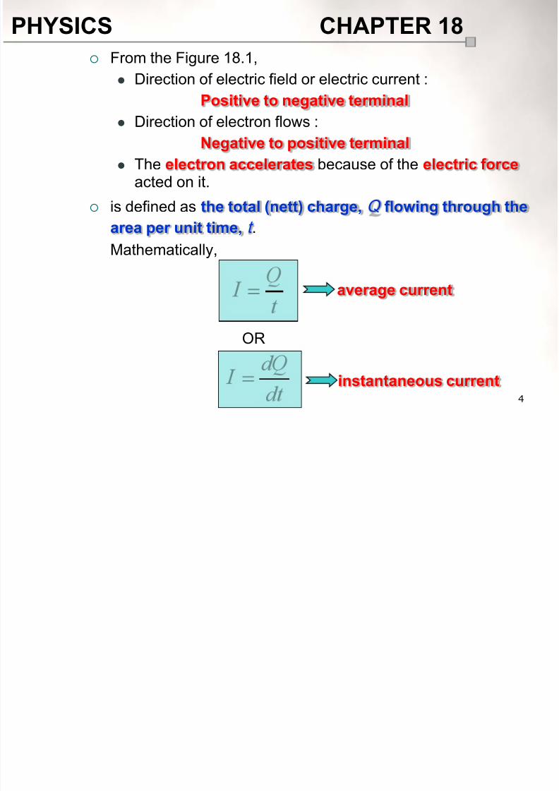
18.1.1 Electric current, I
Consider a simple closed circuit consists of wires, a battery anda light bulb as shown in Figure 18.1.
18.1 Electrical conduction
Area, A
e F
E
I
Figure 18.1
8/10/2019 Chapter18 Student 2
http://slidepdf.com/reader/full/chapter18-student-2 4/118
PHYSICS CHAPTER 18
4
From the Figure 18.1,
Direction of electric field or electric current :
Positive to negative terminal
Direction of electron flows :
Negative to positive terminal
The electron accelerates because of the electric forceacted on it.
is defined as the total (nett) charge, Q flowing through the
area per unit time, t .
Mathematically,
OR
instantaneous current
average current
8/10/2019 Chapter18 Student 2
http://slidepdf.com/reader/full/chapter18-student-2 5/118
PHYSICS CHAPTER 18
5
It is a base and scalar quantities.
The S.I. unit of the electric current is the ampere (A).
1 ampere of current is defined as one coulomb of chargepassing through the surface area in one second.
OR
1
sC1second1
coulomb1
ampere1
Note:
If the charge move around a circuit in the same directionat all times, the current is called direct current (dc), which is
produced by the battery.
8/10/2019 Chapter18 Student 2
http://slidepdf.com/reader/full/chapter18-student-2 6/118
PHYSICS CHAPTER 18
6
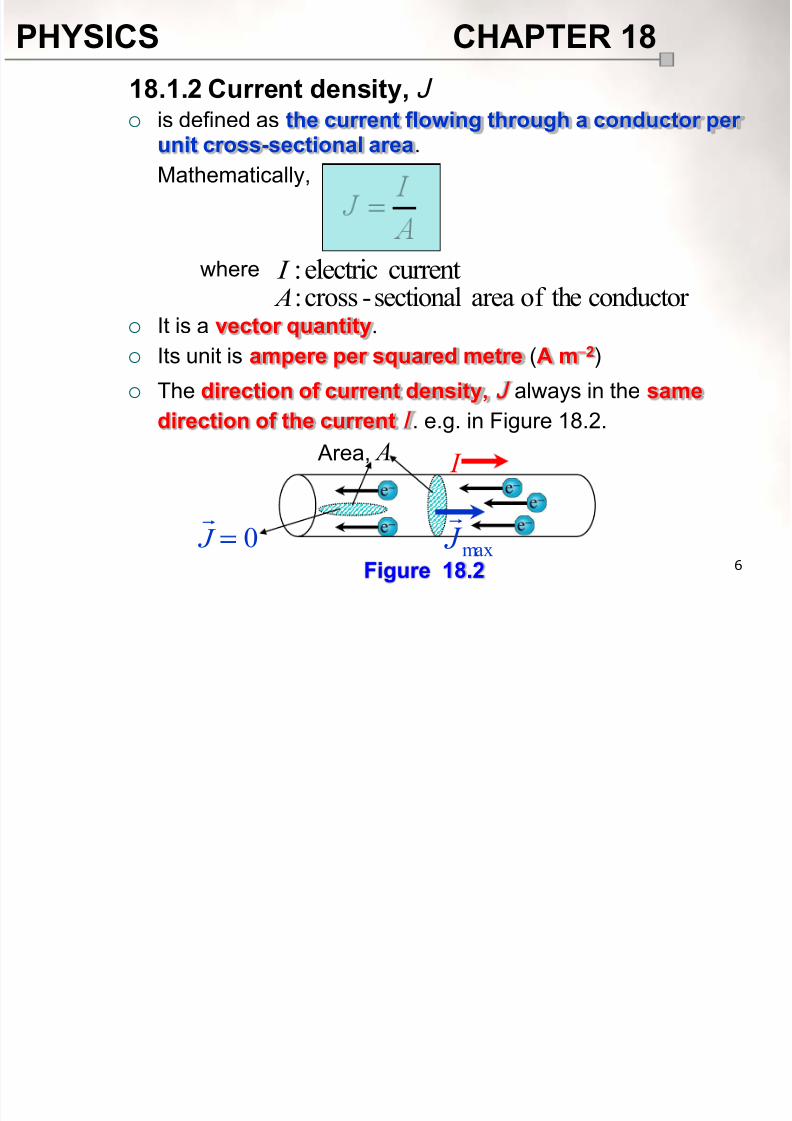
is defined as the current flowing through a conductor per
unit cross-sectional area.
Mathematically,
It is a vector quantity.
Its unit is ampere per squared metre (A m 2)
The direction of current density, J always in the same
direction of the current I . e.g. in Figure 18.2.
18.1.2 Current density, J
where currentelectric: I conductor theof areasectional-cross: A
I
max J
0 J
Area, A
Figure 18.2
8/10/2019 Chapter18 Student 2
http://slidepdf.com/reader/full/chapter18-student-2 7/118
8/10/2019 Chapter18 Student 2
http://slidepdf.com/reader/full/chapter18-student-2 8/118
PHYSICS CHAPTER 18
8
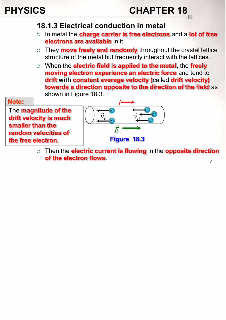
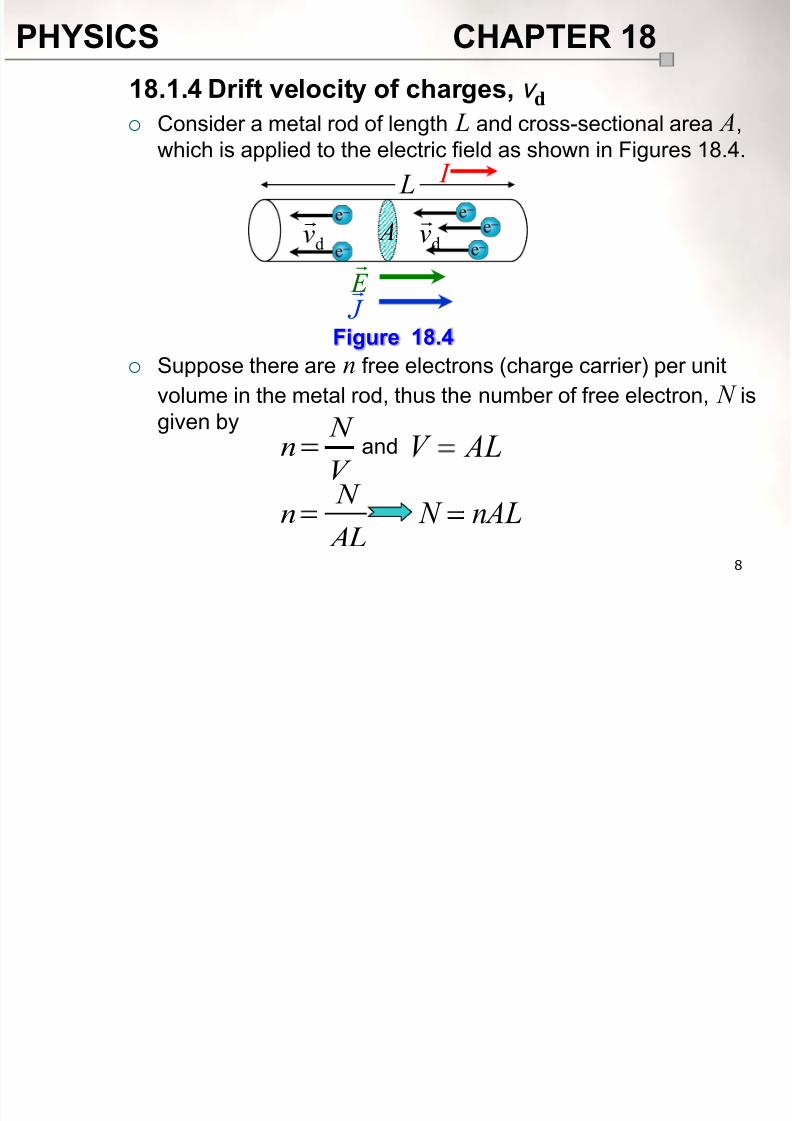
Consider a metal rod of length L and cross-sectional area A,
which is applied to the electric field as shown in Figures 18.4.
Suppose there are n free electrons (charge carrier) per unit
volume in the metal rod, thus the number of free electron, N isgiven by
18.1.4 Drift velocity of charges, v d
E
J
I
dv
dv
L
A
Figure 18.4
V
N n ALV and
AL
N n nAL N
8/10/2019 Chapter18 Student 2
http://slidepdf.com/reader/full/chapter18-student-2 9/118
PHYSICS CHAPTER 18
9
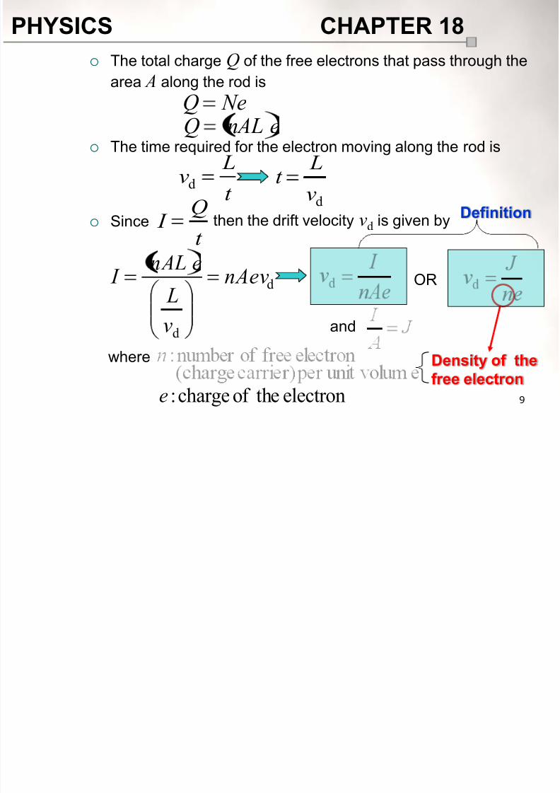
The total charge Q of the free electrons that pass through the
area A along the rod is
The time required for the electron moving along the rod is
Since
NeQenALQ
t
Lvd
dv
Lt
then the drift velocity vd is given by
t
Q I
d
d
nAev
v L
enAL I
and
OR
where
electrontheof charge:e
Definition
Density of the
free electron
8/10/2019 Chapter18 Student 2
http://slidepdf.com/reader/full/chapter18-student-2 10/118
PHYSICS CHAPTER 18
10
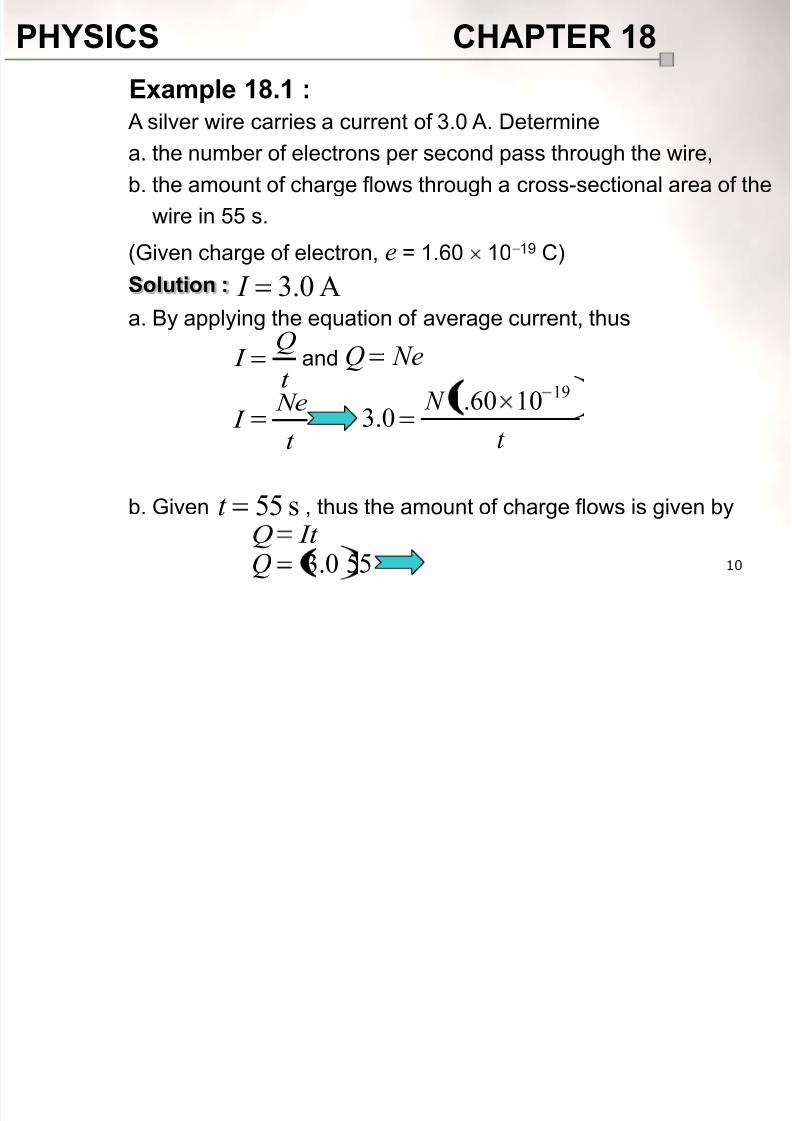
A silver wire carries a current of 3.0 A. Determine
a. the number of electrons per second pass through the wire,
b. the amount of charge flows through a cross-sectional area of the
wire in 55 s.
(Given charge of electron, e = 1.60 10 19 C)
Solution :
a. By applying the equation of average current, thus
b. Given , thus the amount of charge flows is given by
Example 18.1 :
A0.3 I
t
Q I
t N
19
1060.10.3
and NeQ
t Ne I
s55t It Q
550.3Q
8/10/2019 Chapter18 Student 2
http://slidepdf.com/reader/full/chapter18-student-2 11/118
PHYSICS CHAPTER 18
11
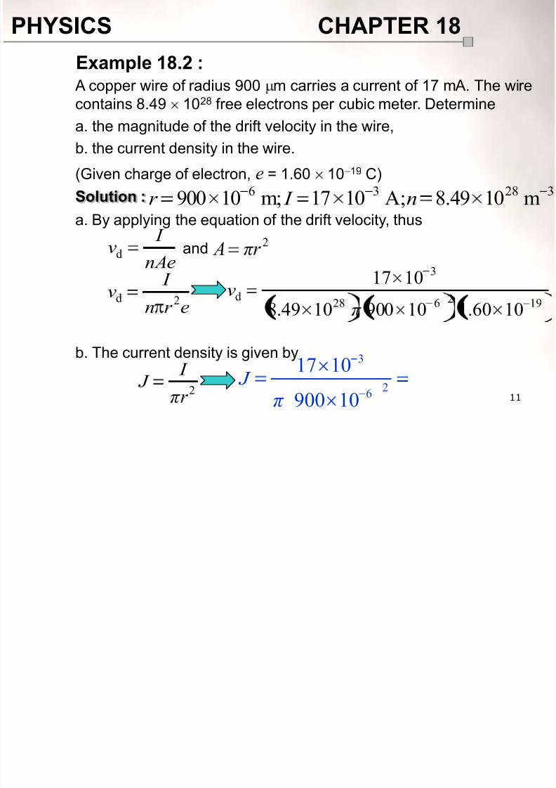
A copper wire of radius 900 m carries a current of 17 mA. The wire
contains 8.49 1028 free electrons per cubic meter. Determine
a. the magnitude of the drift velocity in the wire,
b. the current density in the wire.
(Given charge of electron, e = 1.60 10 19 C)
Solution :
a. By applying the equation of the drift velocity, thus
b. The current density is given by
Example 18.2 :
32836 m1049.8A;1017m;10900 n I r
nAe
I vd
192628
3
d
1060.1109001049.8
1017
π v
and2πr A
er n
I v 2d
2πr
I
J
3
26
17 10
900 10 J
π
8/10/2019 Chapter18 Student 2
http://slidepdf.com/reader/full/chapter18-student-2 12/118
PHYSICS CHAPTER 18
12
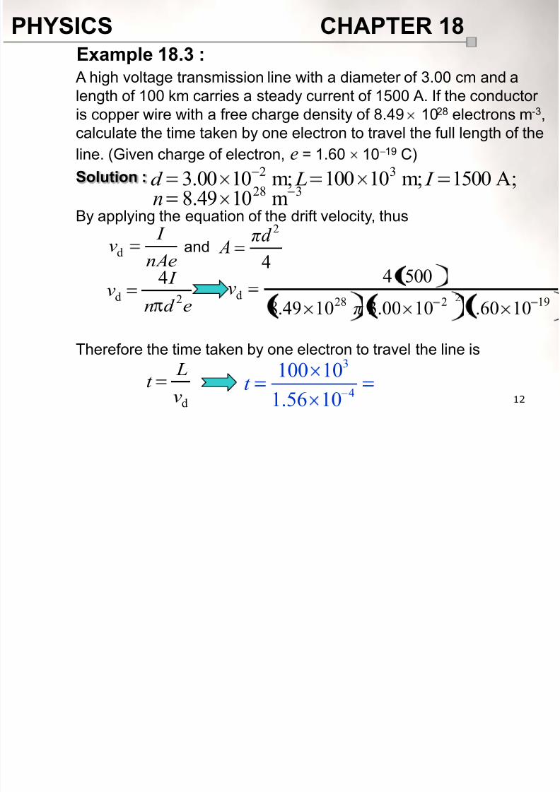
A high voltage transmission line with a diameter of 3.00 cm and a
length of 100 km carries a steady current of 1500 A. If the conductoris copper wire with a free charge density of 8.49 1028 electrons m-3,
calculate the time taken by one electron to travel the full length of the
line. (Given charge of electron, e = 1.60 10 19 C)
Solution :
By applying the equation of the drift velocity, thus
Therefore the time taken by one electron to travel the line is
Example 18.3 :
nAe
I vd
192228d1060.11000.31049.8
15004
π v
and4
2πd A
ed n
I
v 2d
4
dv
Lt
3
4
100 10
1.56 10t
A;1500m;10100m;1000.332
I Ld 328 m1049.8n
8/10/2019 Chapter18 Student 2
http://slidepdf.com/reader/full/chapter18-student-2 13/118
PHYSICS CHAPTER 18
13
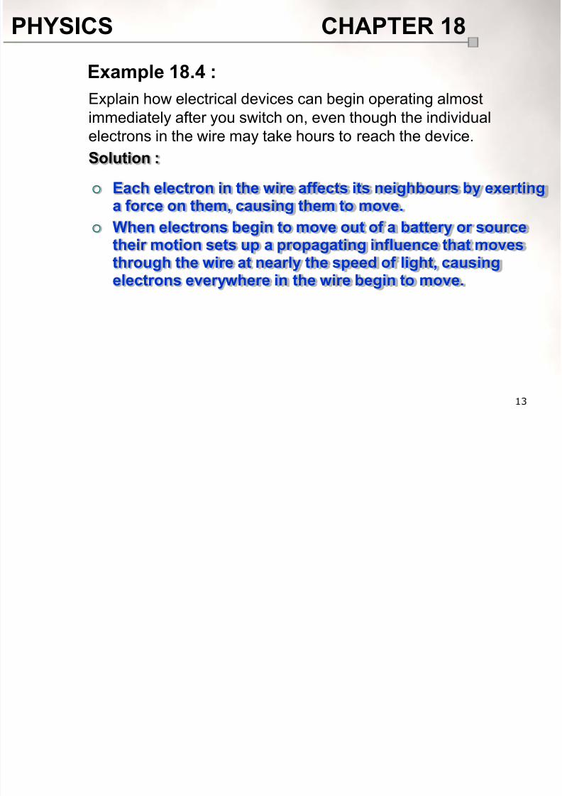
Explain how electrical devices can begin operating almostimmediately after you switch on, even though the individual
electrons in the wire may take hours to reach the device.
Solution :
Example 18.4 :
Each electron in the wire affects its neighbours by exertinga force on them, causing them to move.
When electrons begin to move out of a battery or sourcetheir motion sets up a propagating influence that movesthrough the wire at nearly the speed of light, causingelectrons everywhere in the wire begin to move.
8/10/2019 Chapter18 Student 2
http://slidepdf.com/reader/full/chapter18-student-2 14/118
PHYSICS CHAPTER 18
14
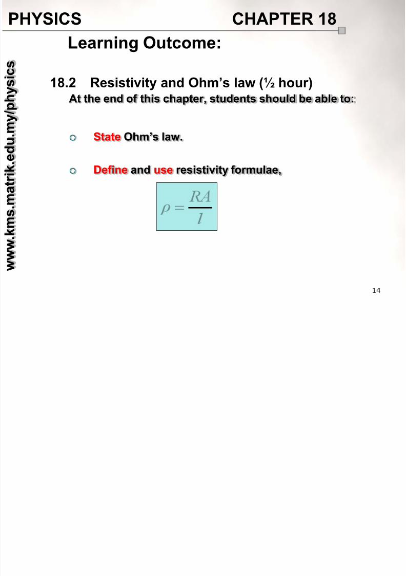
At the end of this chapter, students should be able to:
State Ohm’s law.
Define and use resistivity formulae,
Learning Outcome:
18.2 Resistivity and Ohm’s law (½ hour)
w w w . k m s
. m a t r i k . e
d u
. m y / p h y s i c
s
8/10/2019 Chapter18 Student 2
http://slidepdf.com/reader/full/chapter18-student-2 15/118
PHYSICS CHAPTER 18
15
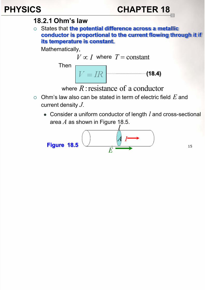
States that the potential difference across a metallic
conductor is proportional to the current flowing through it ifits temperature is constant.
Mathematically,
Ohm’s law also can be stated in term of electric field E and
current density J . Consider a uniform conductor of length l and cross-sectional
area A as shown in Figure 18.5.
18.2.1 Ohm’s law
(18.4)
I V
where conductor aof resistance: R
where constantT Then
Figure 18.5 E
I A
l
8/10/2019 Chapter18 Student 2
http://slidepdf.com/reader/full/chapter18-student-2 16/118
PHYSICS CHAPTER 18
16
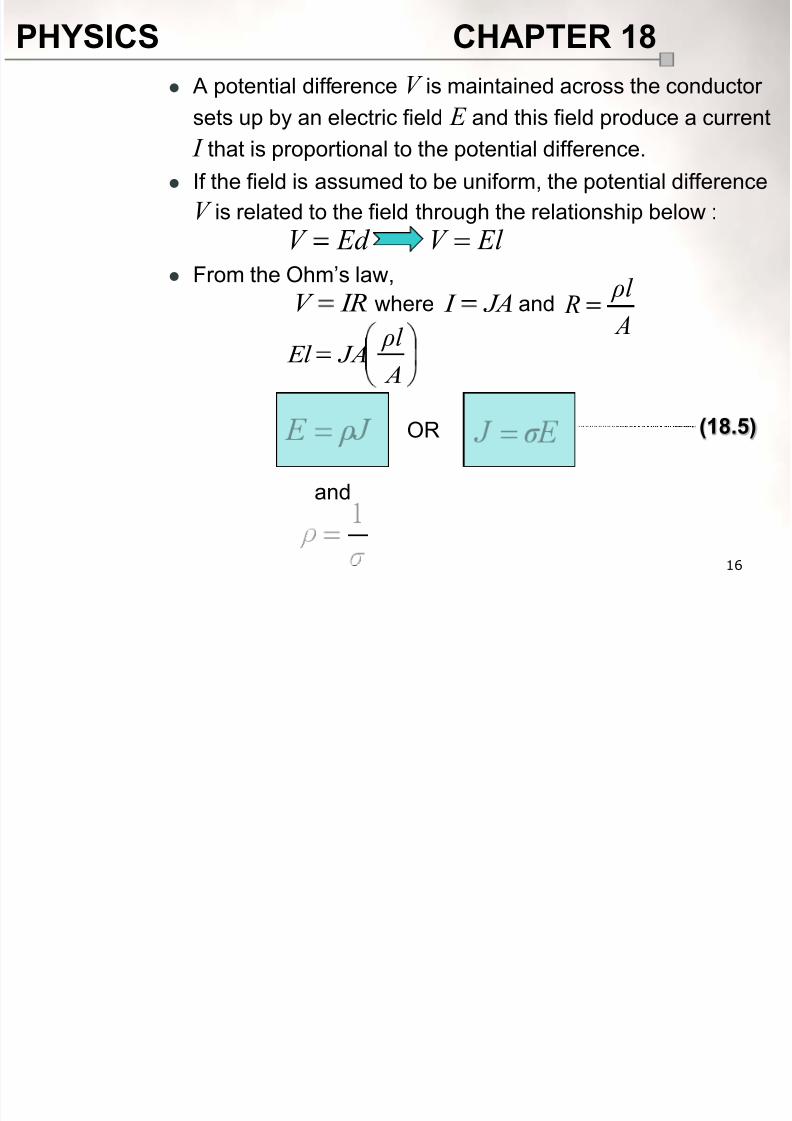
A potential difference V is maintained across the conductor
sets up by an electric field E and this field produce a current
I that is proportional to the potential difference.
If the field is assumed to be uniform, the potential difference
V is related to the field through the relationship below :
From the Ohm’s law,
Ed V El V
IRV JA I where
A
ρl JA El
A
ρl Rand
and
OR (18.5)
8/10/2019 Chapter18 Student 2
http://slidepdf.com/reader/full/chapter18-student-2 17/118
PHYSICS CHAPTER 18
17
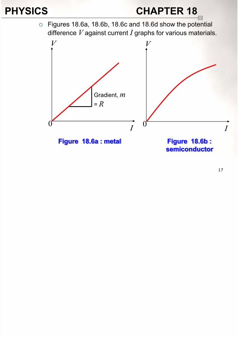
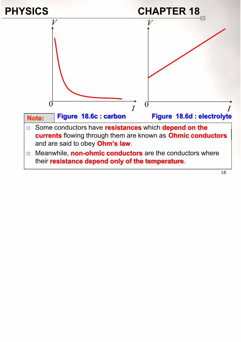
Figures 18.6a, 18.6b, 18.6c and 18.6d show the potential
difference V against current I graphs for various materials.
V
I 0
Gradient, m
= R
Figure 18.6a : metal
V
I 0
Figure 18.6b :
semiconductor
8/10/2019 Chapter18 Student 2
http://slidepdf.com/reader/full/chapter18-student-2 18/118
PHYSICS CHAPTER 18
18
V
I 0
Figure 18.6c : carbon
V
I 0
Figure 18.6d : electrolyteNote:
Some conductors have resistances which depend on thecurrents flowing through them are known as Ohmic conductors
and are said to obey Ohm’s law.
Meanwhile, non-ohmic conductors are the conductors where
their resistance depend only of the temperature.
8/10/2019 Chapter18 Student 2
http://slidepdf.com/reader/full/chapter18-student-2 19/118
PHYSICS CHAPTER 18
19
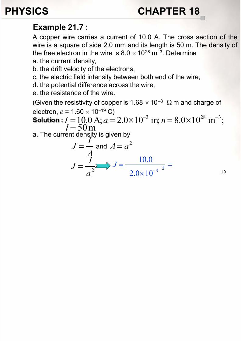
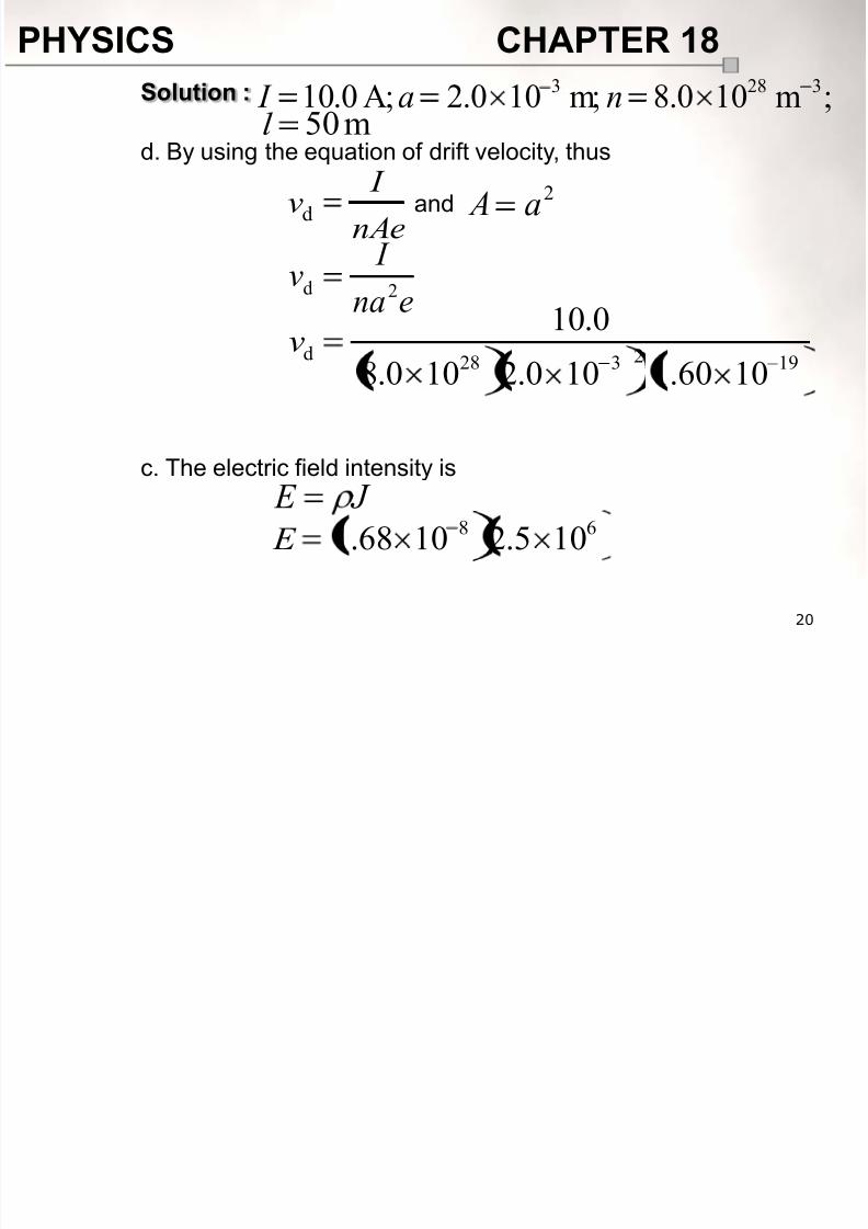
A copper wire carries a current of 10.0 A. The cross section of the
wire is a square of side 2.0 mm and its length is 50 m. The density of the free electron in the wire is 8.0 1028 m 3. Determine
a. the current density,
b. the drift velocity of the electrons,
c. the electric field intensity between both end of the wire,
d. the potential difference across the wire,e. the resistance of the wire.
(Given the resistivity of copper is 1.68 10 8 m and charge of
electron, e = 1.60 10 19 C)
Solution :
a. The current density is given by
Example 21.7 :
;m100.8m;100.2A;0.10 3283 na I m50l
A
I J
2a Aand
2a
I
J 23
10.0
2.0 10 J
8/10/2019 Chapter18 Student 2
http://slidepdf.com/reader/full/chapter18-student-2 20/118
PHYSICS CHAPTER 18
20
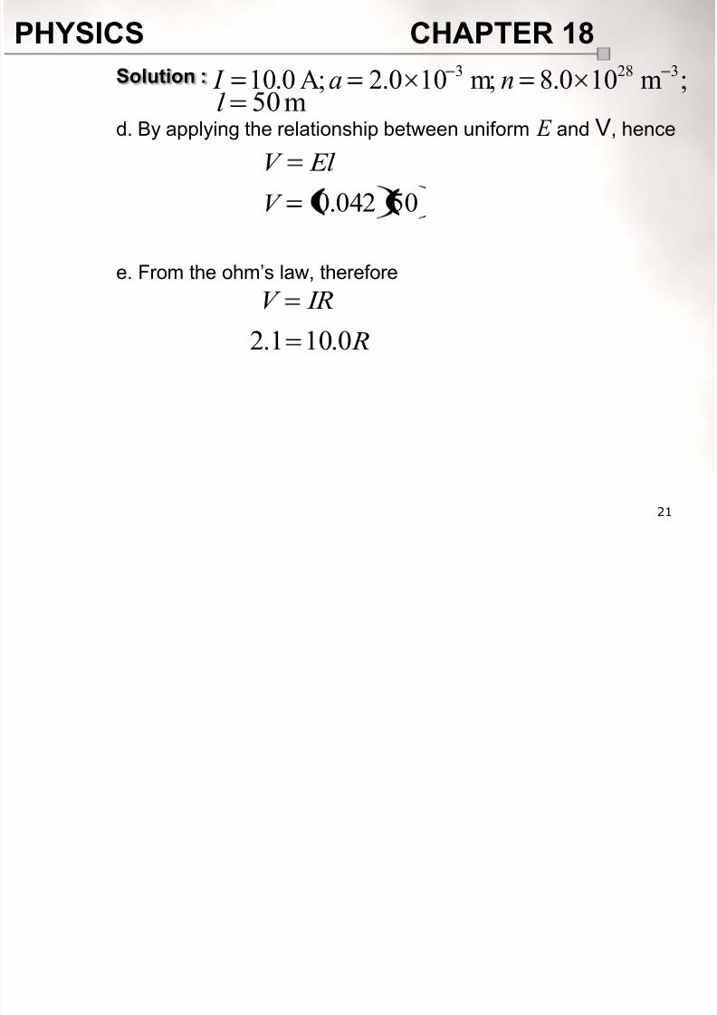
Solution :
d. By using the equation of drift velocity, thus
c. The electric field intensity is
;m100.8m;100.2A;0.10 3283 na I m50l
nAe
I vd
192328d
1060.1100.2100.8
0.10v
and2a A
ena
I v
2d
J E 68 105.21068.1 E
8/10/2019 Chapter18 Student 2
http://slidepdf.com/reader/full/chapter18-student-2 21/118
PHYSICS CHAPTER 18
21
Solution :
d. By applying the relationship between uniform E and V, hence
e. From the ohm’s law, therefore
;m100.8m;100.2A;0.10 3283 na I m50l
El V
50042.0V
IRV
R0.101.2
8/10/2019 Chapter18 Student 2
http://slidepdf.com/reader/full/chapter18-student-2 22/118
PHYSICS CHAPTER 18
22
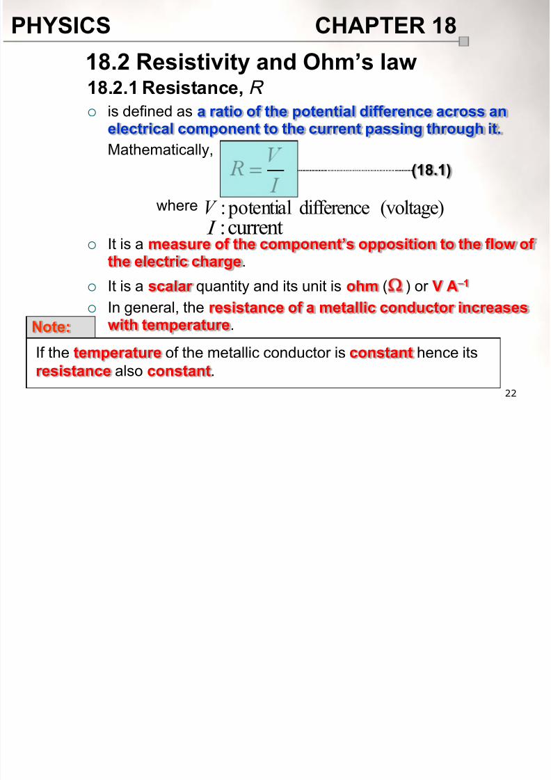
18.2.1 Resistance, R
is defined as a ratio of the potential difference across anelectrical component to the current passing through it.
Mathematically,
It is a measure of the component’s opposition to the flow ofthe electric charge.
It is a scalar quantity and its unit is ohm ( ) or V A1
In general, the resistance of a metallic conductor increaseswith temperature.
18.2 Resistivity and Ohm’s law
where (voltage)difference potential:V current: I
Note:
If the temperature of the metallic conductor is constant hence its
resistance also constant.
(18.1)
8/10/2019 Chapter18 Student 2
http://slidepdf.com/reader/full/chapter18-student-2 23/118
PHYSICS CHAPTER 18
23
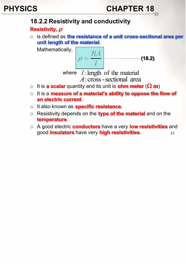
Resistivity,
is defined as the resistance of a unit cross-sectional area perunit length of the material.
Mathematically,
It is a scalar quantity and its unit is ohm meter ( m)
It is a measure of a material’s ability to oppose the flow of
an electric current. It also known as specific resistance.
Resistivity depends on the type of the material and on thetemperature.
A good electric conductors have a very low resistivities and
good insulators have very high resistivities.
18.2.2 Resistivity and conductivity
where materialtheof length:l areasectional-cross: A
(18.2)
8/10/2019 Chapter18 Student 2
http://slidepdf.com/reader/full/chapter18-student-2 24/118
PHYSICS CHAPTER 18
24
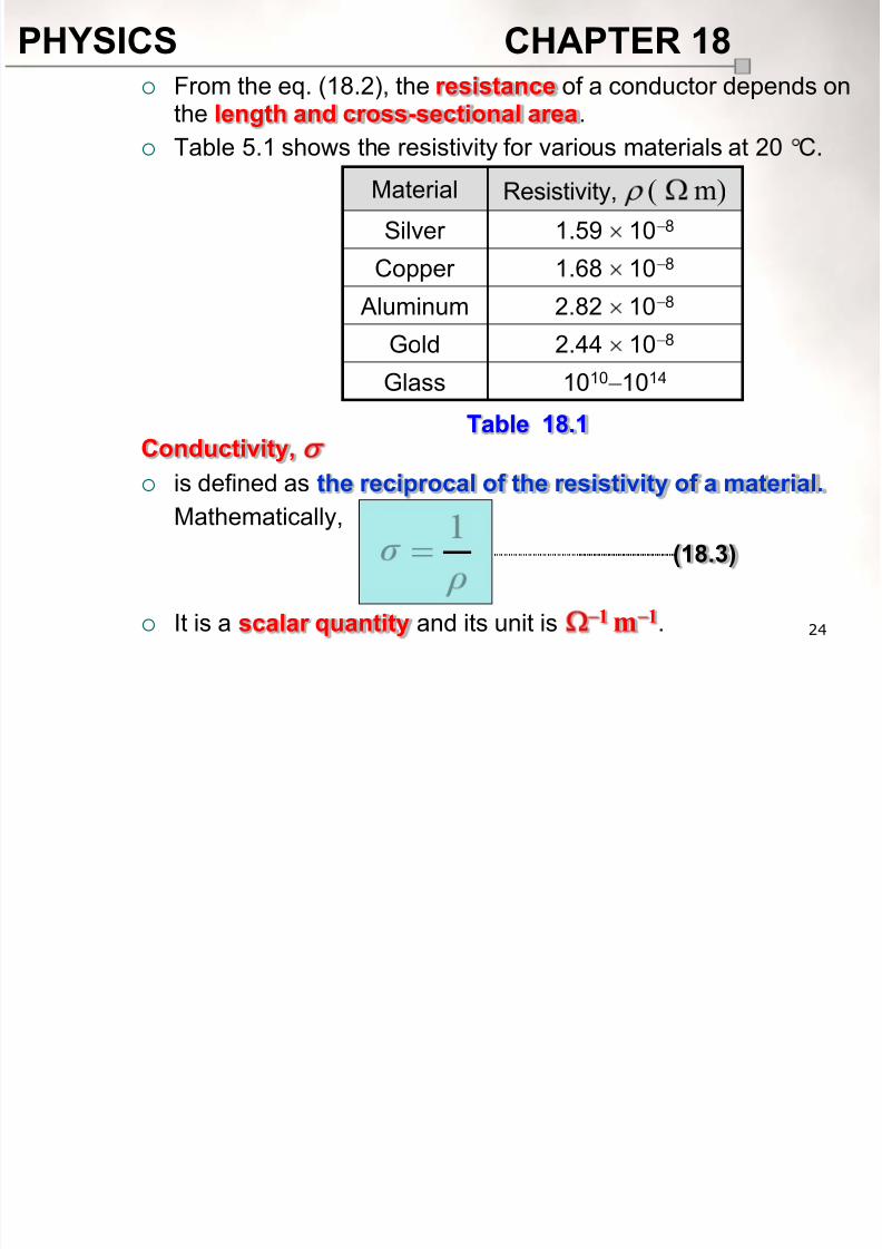
From the eq. (18.2), the resistance of a conductor depends onthe length and cross-sectional area.
Table 5.1 shows the resistivity for various materials at 20 C.
Conductivity,
is defined as the reciprocal of the resistivity of a material.
Mathematically,
It is a scalar quantity and its unit is 1m 1.
Material Resistivity, ( m)
Silver 1.59 10 8
Copper 1.68 10 8
Aluminum 2.82 108
Gold 2.44 10 8
Glass 1010 1014
Table 18.1
(18.3)
8/10/2019 Chapter18 Student 2
http://slidepdf.com/reader/full/chapter18-student-2 25/118
PHYSICS CHAPTER 18
25
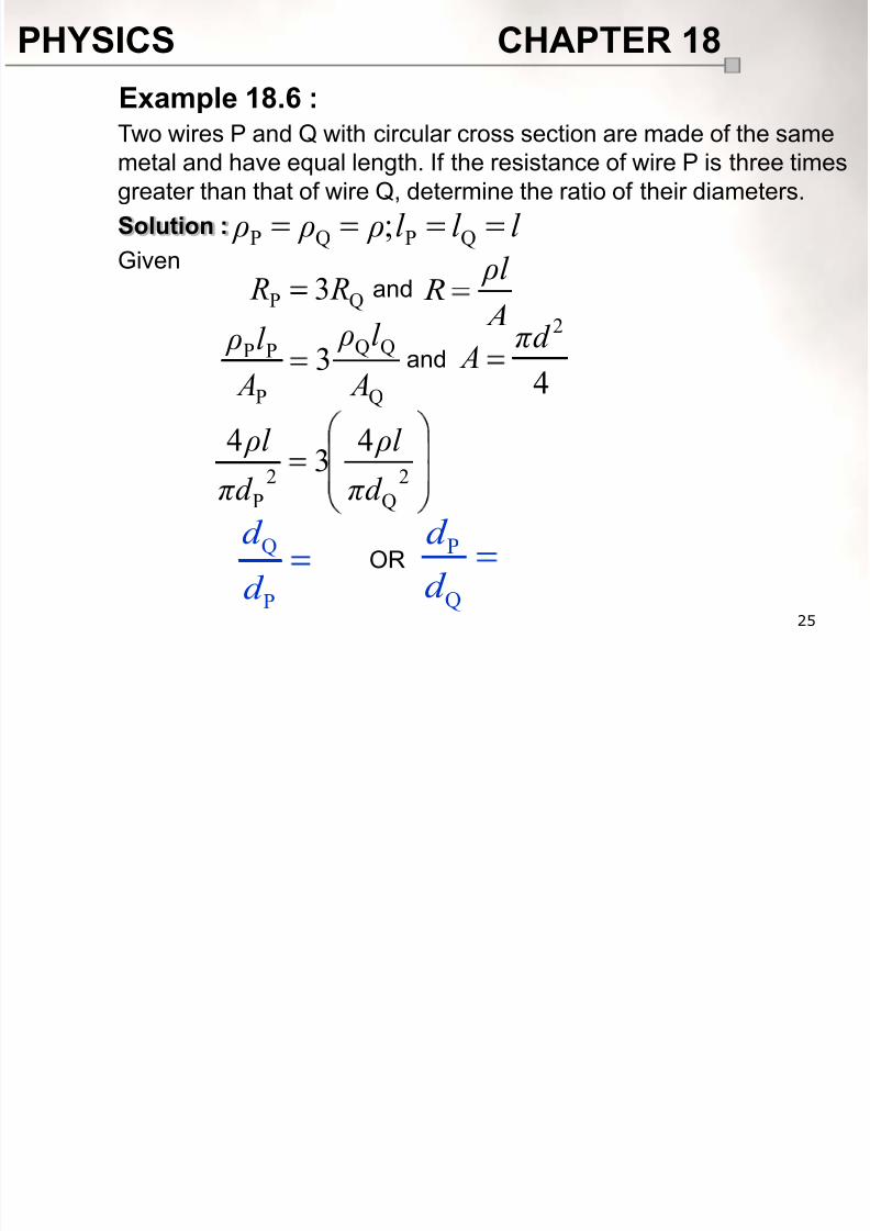
Two wires P and Q with circular cross section are made of the same
metal and have equal length. If the resistance of wire P is three timesgreater than that of wire Q, determine the ratio of their diameters.
Solution :
Given
Example 18.6 :
l l l ρ ρ ρ QPQP ;
QP3 R R and
A
ρl R
Q
P
d
d
Q
P
PP 3 A
l ρ
A
l ρand
4
2πd A
2
Q
2
P
43
4
πd
ρl
πd
ρl
ORP
Q
d
d
8/10/2019 Chapter18 Student 2
http://slidepdf.com/reader/full/chapter18-student-2 26/118
PHYSICS CHAPTER 18
26
When a potential difference of 240 V is applied across a wire that is
200 cm long and has a 0.50 mm radius, the current density is7.14 109 A m 2. Calculate
a. the resistivity of the wire,
b. the conductivity of the wire.
Solution :
a. From the definition of resistance, thus
b. The conductivity of the wire is given by
Example 18.7 :
I
V R where
A
ρl R
JA
V
A
ρl 91014.7
240
00.2 ρ
8
1
1.68 10σ
m;1050.0m;00.2V;240 3r l V
29 mA1014.7 J
and JA I
ρσ
1
8/10/2019 Chapter18 Student 2
http://slidepdf.com/reader/full/chapter18-student-2 27/118
PHYSICS CHAPTER 18
27
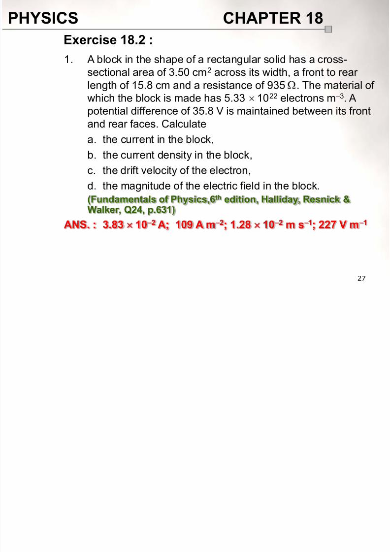
Exercise 18.2 :
1. A block in the shape of a rectangular solid has a cross-
sectional area of 3.50 cm2 across its width, a front to rearlength of 15.8 cm and a resistance of 935 . The material of
which the block is made has 5.33 1022 electrons m 3. A
potential difference of 35.8 V is maintained between its front
and rear faces. Calculate
a. the current in the block,
b. the current density in the block,
c. the drift velocity of the electron,
d. the magnitude of the electric field in the block.
(Fundamentals of Physics,6th edition, Halliday, Resnick &Walker, Q24, p.631)
ANS. : 3.83 10 2 A; 109 A m 2; 1.28 10 2 m s 1; 227 V m 1
8/10/2019 Chapter18 Student 2
http://slidepdf.com/reader/full/chapter18-student-2 28/118
PHYSICS CHAPTER 18
28
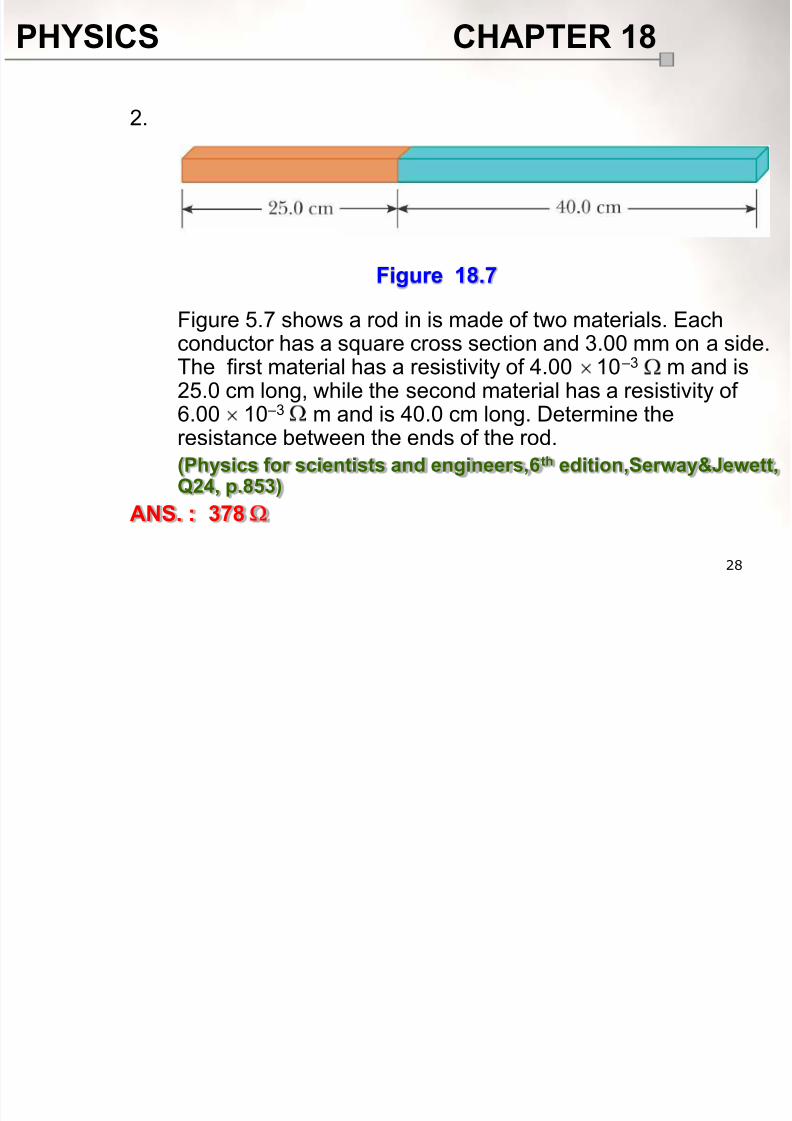
2.
Figure 5.7 shows a rod in is made of two materials. Eachconductor has a square cross section and 3.00 mm on a side.The first material has a resistivity of 4.00 10 –3 m and is25.0 cm long, while the second material has a resistivity of
6.00 10 –3
m and is 40.0 cm long. Determine theresistance between the ends of the rod.
(Physics for scientists and engineers,6th edition,Serway&Jewett,Q24, p.853)
ANS. : 378
Figure 18.7
8/10/2019 Chapter18 Student 2
http://slidepdf.com/reader/full/chapter18-student-2 29/118
PHYSICS CHAPTER 18
29
3. A 2.0 m length of wire is made by welding the end of a 120 cm
long silver wire to the end of an 80 cm long copper wire. Eachpiece of wire is 0.60 mm in diameter. A potential difference of
5.0 V is maintained between the ends of the 2.0 m composite
wire. Determine
a. the current in the copper and silver wires.
b. the magnitude of the electric field in copper and silverwires.
c. the potential difference between the ends of the silver
section of wire.
(Given (silver) is 1.47 108
m and (copper) is 1.7210 8 m)
(University physics,11th edition, Young&Freedman, Q25.56,
p.976)
ANS. : 45 A; 2.76 V m 1, 2.33 V m 1; 2.79 V
8/10/2019 Chapter18 Student 2
http://slidepdf.com/reader/full/chapter18-student-2 30/118
PHYSICS CHAPTER 18
30
At the end of this chapter, students should be able to:
Explain the effect of temperature on electrical resistance
in metals and superconductors
Define and explain temperature coefficient of resistivity,.
Apply resistance :
Learning Outcome:
18.3 Variation of resistance with temperature(1 hour)
w w w . k m s
. m a t r i k . e
d u
. m y / p h y s i c
s
8/10/2019 Chapter18 Student 2
http://slidepdf.com/reader/full/chapter18-student-2 31/118
PHYSICS CHAPTER 18
31
18.3.1 Effect of temperature on resistance
Metal
When the temperature increases, the number of free
electrons per unit volume in metal remains unchanged.
Metal atoms in the crystal lattice vibrate with greateramplitude and cause the number of collisions between thefree electrons and metal atoms increase. Hence the resistancein the metal increases.
Superconductor Superconductor is a class of metals and compound whose
resistance decreases to zero when they are below the
critical temperature T c.
18.3 Variation of resistance with
temperature
8/10/2019 Chapter18 Student 2
http://slidepdf.com/reader/full/chapter18-student-2 32/118
PHYSICS CHAPTER 18
32
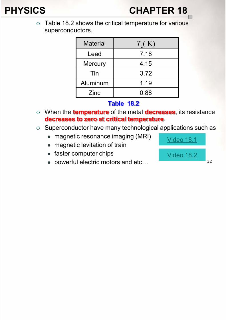
Table 18.2 shows the critical temperature for varioussuperconductors.
When the temperature of the metal decreases, its resistance
decreases to zero at critical temperature. Superconductor have many technological applications such as
magnetic resonance imaging (MRI)
magnetic levitation of train
faster computer chips
powerful electric motors and etc…
Material T c( K)
Lead 7.18
Mercury 4.15
Tin 3.72
Aluminum 1.19
Zinc 0.88
Table 18.2
Video 18.1
Video 18.2
8/10/2019 Chapter18 Student 2
http://slidepdf.com/reader/full/chapter18-student-2 33/118
PHYSICS CHAPTER 18
33
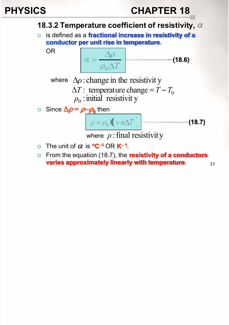
is defined as a fractional increase in resistivity of a
conductor per unit rise in temperature.OR
Since =0
then
The unit of is C 1 OR K 1.
From the equation (18.7), the resistivity of a conductors
varies approximately linearly with temperature.
18.3.2 Temperature coefficient of resistivity,
where yresistivitin thechange: ρ0changeure temperat: T T T
yresistivitinitial:0 ρ
yresistivitfinal: ρwhere
(18.6)
(18.7)

8/10/2019 Chapter18 Student 2
http://slidepdf.com/reader/full/chapter18-student-2 34/118
PHYSICS CHAPTER 18
34
From the definition of resistivity, thus
then the equation (18.7) can be expressed as
Table 18.3 shows the temperature coefficients of resistivity forvarious materials.
R ρ
(18.8)
where resistanceinitial:0 Rresistancefinal: R
Material ( C 1)
Silver 4.10 10 3
Mercury 0.89 10 3
Iron 6.51 10 3
Aluminum 4.29 10 3
Copper 6.80 10 3
Table 18.3

8/10/2019 Chapter18 Student 2
http://slidepdf.com/reader/full/chapter18-student-2 35/118
PHYSICS CHAPTER 18
35
Figures 18.7a, 18.7b, 18.7c and 18.7d show the resistance Ragainst temperature T graphs for various materials.
R
T 0
0 R
cT
Figure 18.7a : metal Figure 18.7b : semiconductor
R
T 0
R
T 0Figure 18.7c : superconductor
R
T 0Figure 18.7d : carbon

8/10/2019 Chapter18 Student 2
http://slidepdf.com/reader/full/chapter18-student-2 36/118
PHYSICS CHAPTER 18

8/10/2019 Chapter18 Student 2
http://slidepdf.com/reader/full/chapter18-student-2 37/118
PHYSICS CHAPTER 18
37
Solution :
b. Given
By using the equation for temperature variation of resistance,thus
C27C;20;1025 03
0 T T R
T α R R 100 I
V Randwhere
I
V R
A100.10 30 I
T α
I
V
I
V 1
0
271080.61100.10
11 3
3 I
PHYSICS CHAPTER 18

8/10/2019 Chapter18 Student 2
http://slidepdf.com/reader/full/chapter18-student-2 38/118
PHYSICS CHAPTER 18
38
At the end of this chapter, students should be able to:
Define emf,
Explain the difference between emf of a battery and
potential difference across the battery terminals.
Apply formulae,
Learning Outcome:
18.4 Electromotive force (emf), potential
difference and internal resistance (½ hour)
w w w . k m s
. m a t r i k . e
d u
. m y / p h y s i c
s
PHYSICS CHAPTER 18

8/10/2019 Chapter18 Student 2
http://slidepdf.com/reader/full/chapter18-student-2 39/118
PHYSICS CHAPTER 18
39
18.4.1 Emf, and potential difference, V
Consider a circuit consisting of a battery (cell) that is connected
by wires to an external resistor R as shown in Figure 18.8.
18.4 Electromotive force (emf), potential
difference and internal resistance
I Battery (cell)
A Br ε
R
I
Figure 18.8
PHYSICS CHAPTER 18

8/10/2019 Chapter18 Student 2
http://slidepdf.com/reader/full/chapter18-student-2 40/118
PHYSICS CHAPTER 18
40
A current I flows from the terminal A to the terminal B.
For the current to flow continuously from terminal A to B, a
source of electromotive force (e.m.f.), is required such asbattery to maintained the potential difference between point Aand point B.
Electromotive force (emf), is defined as the energy providedby the source (battery/cell) to each unit charge that flows
through the external and internal resistances.
Terminal potential difference (voltage), V is defined as the work
done in bringing a unit (test) charge from the negative tothe positive terminals of the battery through the externalresistance only.
The unit for both e.m.f. and potential difference are volt (V).
When the current I flows naturally from the battery there is an
internal drop in potential difference (voltage) equal to Ir . Thus
the terminal potential difference (voltage), V is given by
PHYSICS CHAPTER 18

8/10/2019 Chapter18 Student 2
http://slidepdf.com/reader/full/chapter18-student-2 41/118
PHYSICS CHAPTER 18
41
then
Equation (18.9) is valid if the battery (cell) supplied the
current to the circuit where
For the battery without internal resistance or if no currentflows in the circuit (open circuit), then equation (18.9) can bewritten as
(18.9)
and IRV
(18.10)
where e.m.f.:ε
(voltage)difference potentialterminal:V r OR difference potentialindropinternal: V Ir
resistanceexternaltotal: R(battery)cellaof resistanceinternal:r
V ε
V ε
PHYSICS CHAPTER 18

8/10/2019 Chapter18 Student 2
http://slidepdf.com/reader/full/chapter18-student-2 42/118
PHYSICS CHAPTER 18
42
is defined as the resistance of the chemicals inside the
battery (cell) between the poles and is given by
The value of internal resistance depends on the type ofchemical material in the battery.
The symbol of emf and internal resistance in the electrical circuit
are shown in Figures 18.9a and 18.9b.
18.4.2 Internal resistance of a battery, r
when the cell (battery) is used.
where resistanceinternalacrossdifference potential:r V circuitin thecurrent: I
r εOR
Figure 18.9a Figure 18.9b
PHYSICS CHAPTER 18

8/10/2019 Chapter18 Student 2
http://slidepdf.com/reader/full/chapter18-student-2 43/118
PHYSICS CHAPTER 18
43
A battery has an emf of 9.0 V and an internal resistance of 6.0 .
Determinea. the potential difference across its terminals when it is supplying a
current of 0.50 A,
b. the maximum current which the battery could supply.
Solution :
a. GivenBy applying the expression for emf, thus
b. The current is maximum when the total external resistance, R =0,therefore
Example 18.9 :
0.6V;0.9 r ε
A50.0 I
0.650.00.9 V Ir V ε
0.600.9 max I
r R I ε
PHYSICS CHAPTER 18

8/10/2019 Chapter18 Student 2
http://slidepdf.com/reader/full/chapter18-student-2 44/118
PHYSICS CHAPTER 18
44
A car battery has an emf of 12.0 V and an internal resistance of
1.0 . The external resistor of resistance 5.0 is connected in serieswith the battery as shown in Figure 18.10.
Determine the reading of the ammeter and voltmeter if both meters
are ideal.
Example 18.10 :
R
V
r
A
Figure 18.10
PHYSICS CHAPTER 18

8/10/2019 Chapter18 Student 2
http://slidepdf.com/reader/full/chapter18-student-2 45/118
PHYSICS CHAPTER 18
45
Solution :
By applying the equation of e.m.f., the current in the circuit is
Therefore the reading of the ammeter is .
The voltmeter measures the potential difference across the
terminals of the battery equal to the potential difference across
the total external resistor , thus its reading is
0.5;0.1V;0.12 Rr ε
IRV
r R I ε
0.10.50.12 I
0.50.2V

8/10/2019 Chapter18 Student 2
http://slidepdf.com/reader/full/chapter18-student-2 46/118
PHYSICS CHAPTER 18

8/10/2019 Chapter18 Student 2
http://slidepdf.com/reader/full/chapter18-student-2 47/118
PHYSICS CHAPTER 18
47
is defined as the energy liberated per unit time in the
electrical device.
The electrical power P supplied to the electrical device is given
by
When the electric current flows through wire or passive resistor,hence the potential difference across it is
then the electrical power can be written as
It is a scalar quantity and its unit is watts (W).
18.5.2 Power, P
t
VIt
t
W P
(18.11)
IRV
OR (18.12)
PHYSICS CHAPTER 18

8/10/2019 Chapter18 Student 2
http://slidepdf.com/reader/full/chapter18-student-2 48/118
PHYSICS CHAPTER 18
48
In Figure 18.11, a battery has an emf of 12 V and an internal
resistance of 1.0 . Determinea. the rate of energy transferred to electrical energy in the battery,
b. the rate of heat dissipated in the battery,
c. the amount of heat loss in the 5.0 resistor if the current flows
through it for 20 minutes.
Example 18.11 :
Figure 18.11
R
r
PHYSICS CHAPTER 18

8/10/2019 Chapter18 Student 2
http://slidepdf.com/reader/full/chapter18-student-2 49/118
PHYSICS CHAPTER 18
49
Solution :
The current in the circuit is given by
a. The rate of energy transferred to electrical energy (power) in the
battery is
b. The rate of heat dissipated due to the internal resistance is
c. GivenThe amount of heat loss in the resistor is
0.5;0.1V;0.12 Rr ε
I ε P
A0.2 I r R I ε 0.10.50.12 I
0.120.2 P
r I P 2 0.10.2
2 P
s12006020t
Rt I H 2 12000.50.22
H
PHYSICS CHAPTER 18

8/10/2019 Chapter18 Student 2
http://slidepdf.com/reader/full/chapter18-student-2 50/118
PHYSICS CHAPTER 18
50
18.5.1 Electrical energy, E
Consider a circuit consisting of a battery that is connected bywires to an electrical device (such as a lamp, motor or batterybeing charged) as shown in Figure 18.12 where the potential
different across that electrical device is V .
18.5 Electrical energy and power
Figure 18.12
Electrical device
A B
V I I
PHYSICS CHAPTER 18

8/10/2019 Chapter18 Student 2
http://slidepdf.com/reader/full/chapter18-student-2 51/118
PHYSICS CHAPTER 18
51
A current I flows from the terminal A to the terminal B, if it flows
for time t , the charge Q which it carries from B to A is given by
Then the work done on this charge Q from B to A (equal to the
electrical energy supplied) is
If the electrical device is passive resistor (device whichconvert all the electrical energy supplied into heat), the heat
dissipated H is given by
QV W
It Q
(18.13)
OR
(18.14)
PHYSICS CHAPTER 18

8/10/2019 Chapter18 Student 2
http://slidepdf.com/reader/full/chapter18-student-2 52/118
PHYSICS CHAPTER 18
52
Cells in series
Consider two cells are connected in series as shown in Figure18.13.
The total emf, and the total internal resistance, r are given by
18.5.3 Combination of cells
1r 2r 1ε 2ε
Figure 18.13
and
(18.15)
(18.16)Note:
If one cell, e.m.f. 2 say, is turned round ‘in opposition’ to theothers, then but the total internal resistance remainsunaltered.
21 εεε
PHYSICS CHAPTER 18

8/10/2019 Chapter18 Student 2
http://slidepdf.com/reader/full/chapter18-student-2 53/118
PHYSICS CHAPTER 18
53
Cells in parallel
Consider two equal cells are connected in parallel as shown in
Figure 18.14.
The total emf, and the total internal resistance, r are given by
1r
1r
1ε
1ε
Figure 18.14
and
(18.17)
(18.18)
Note:
If different cells are connected in parallel, there is no simpleformula for the total emf and the total internal resistance where
Kirchhoff’s laws have to be used.
PHYSICS CHAPTER 18

8/10/2019 Chapter18 Student 2
http://slidepdf.com/reader/full/chapter18-student-2 54/118
PHYSICS CHAPTER 18
54
Exercise 18.3 :
1. A wire of unknown composition has a resistance of 35.0
when immersed in the water at 20.0 C. When the wire isplaced in the boiling water, its resistance rises to 47.6 .
Calculate the temperature on a hot day when the wire has a
resistance of 37.8 .
(Physics,7th edition, Cutnell & Johnson, Q15, p.639)
ANS. : 37.8 C2. a. A battery of emf 6.0 V is connected across a 10 resistor.
If the potential difference across the resistor is 5.0 V,
determine
i. the current in the circuit,
ii. the internal resistance of the battery.
b. When a 1.5 V dry cell is short-circuited, a current of 3.0 Aflows through the cell. What is the internal resistance of thecell?
ANS. : 0.50 A, 2.0 ; 0.50
PHYSICS CHAPTER 18

8/10/2019 Chapter18 Student 2
http://slidepdf.com/reader/full/chapter18-student-2 55/118
PHYSICS CHAPTER 18
55
3. An electric toy of resistance 2.50 is operated by a dry cell of
emf 1.50 V and an internal resistance 0.25 .a. What is the current does the toy drawn?
b. If the cell delivers a steady current for 6.00 hours, calculate
the charge pass through the toy.
c. Determine the energy was delivered to the toy.
ANS. : 0.55 A; 1.19 104 C; 16.3 kJ
4. A wire 5.0 m long and 3.0 mm in diameter has a resistance of
100 . A 15 V of potential difference is applied across the
wire. Determine
a. the current in the wire,b. the resistivity of the wire,
c. the rate at which heat is being produced in the wire.
(College Physics,6th edition, Wilson, Buffa & Lou, Q75, p.589)
ANS. : 0.15 A; 1.40 10 4 m; 2.30 W
PHYSICS CHAPTER 18

8/10/2019 Chapter18 Student 2
http://slidepdf.com/reader/full/chapter18-student-2 56/118
PHYSICS CHAPTER 18
56
At the end of this chapter, students should be able to:
Deduce and calculate effective resistance of resistors
in series and parallel.
Learning Outcome:
18.6 Resistors in series and parallel (1 hour)
w w w . k m s . m a t r i k . e
d u . m y / p h y s i c
s
PHYSICS CHAPTER 18

8/10/2019 Chapter18 Student 2
http://slidepdf.com/reader/full/chapter18-student-2 57/118
PHYSICS CHAPTER 18
57
18.6.1 Resistors in series
The symbol of resistor in an electrical circuit can be shown inFigure 18.15.
Consider three resistors are connected in series to the batteryas shown in Figure 18.16.
18.6 Resistors in series and parallel
OR
R R
Figure 18.15
1 R 2 R3 R
V
1V 2V 3V
I I
Figure 18.16
PHYSICS CHAPTER 18

8/10/2019 Chapter18 Student 2
http://slidepdf.com/reader/full/chapter18-student-2 58/118
PHYSICS CHAPTER 18
58
Characteristics of resistors in series
The same current I flows through each resistor where
Assuming that the connecting wires have no resistance, the
total potential difference, V is given by
From the definition of resistance, thus
Substituting for V 1, V 2 , V 3 and V in the eq. (18.19) gives
(18.19)
(18.20)
where resistancet)(equivaleneffective:eff R
PHYSICS CHAPTER 18

8/10/2019 Chapter18 Student 2
http://slidepdf.com/reader/full/chapter18-student-2 59/118
PHYSICS CHAPTER 18
59
V
1 R
3 R
2 R
Consider three resistors are connected in parallel to the battery
as shown in Figures 18.17a and 18.17b.
18.6.2 Resistors in parallel
I I
2 I
1 I
3 I
1V 2V
3V V 1 R
3 R2 R
I
I
1 I
3 I
2 I
Figure 18.17a
Figure 18.17b
2V
3V
1V
PHYSICS CHAPTER 18

8/10/2019 Chapter18 Student 2
http://slidepdf.com/reader/full/chapter18-student-2 60/118
PHYSICS CHAPTER 18
60
Characteristics of resistors in parallel
There same potential difference, V across each resistor
where
The charge is conserved, therefore the total current I in the
circuit is given by
From the definition of resistance, thus
Substituting for I 1, I
2, I
3and I in the eq. (18.21) gives
(18.21)
(18.22)
PHYSICS CHAPTER 18

8/10/2019 Chapter18 Student 2
http://slidepdf.com/reader/full/chapter18-student-2 61/118
PHYSICS CHAPTER 18
61
For the circuit in Figure 18.18, calculate
a. the effective resistance of the circuit,
b. the current passes through the 12 resistor,c. the potential difference across 4.0 resistor,
d. the power delivered by the battery.
The internal resistance of the battery may be ignored.
Example 18.15 :
Figure 18.18
0.4
0.2
V0.8
12
PHYSICS CHAPTER 18

8/10/2019 Chapter18 Student 2
http://slidepdf.com/reader/full/chapter18-student-2 62/118
PHYSICS CHAPTER 18
62
Solution :
a.
The resistors R1 and R2 are in series, thus R12 is
Since R12 and R3 are in parallel, therefore Reff is given by
V0.8;0.2;12;0.4 321 V R R R
1 R
V
2 R
3 R
12 R
V
3 R
1612 R
2112 R R R 120.412 R
312eff
111
R R R 2
1
16
11
eff R
PHYSICS CHAPTER 18

8/10/2019 Chapter18 Student 2
http://slidepdf.com/reader/full/chapter18-student-2 63/118
PHYSICS CHAPTER 18
63
Solution :
b. Since R12 and R3 are in parallel, thus
Therefore the current passes through R2 is given by
c. Since R1 and R2 are in series, thus
Hence the potential difference across R1 is
d. The power delivered by the battery is
V0.8;0.2;12;0.4 321 V R R R
V0.8312 V V V
12
122
R
V I
A50.021 I I
111 R I V
16
0.82 I
0.450.01V
eff
2
R
V P
78.1
0.82
P
PHYSICS CHAPTER 18

8/10/2019 Chapter18 Student 2
http://slidepdf.com/reader/full/chapter18-student-2 64/118
PHYSICS CHAPTER 18
64
For the circuit in Figure 18.19, calculate the effective resistancebetween the points A and B.
Solution : ;20;10;0.5;0.5 4321 R R R R 105 R
Example 18.16 :
Figure 18.19 0.5
10 10
A
B
0.5
20
2 R
3 R5 R
A
B
1 R
4 R
3 R5 R
A
B
12 R
4 R

8/10/2019 Chapter18 Student 2
http://slidepdf.com/reader/full/chapter18-student-2 65/118
PHYSICS CHAPTER 18

8/10/2019 Chapter18 Student 2
http://slidepdf.com/reader/full/chapter18-student-2 66/118
PHYSICS CHAPTER 18
66
Solution :
Since R1234 and R5 are connected in parallel , therefore the
effective resistance Reff is given by
;20;10;0.5;0.5 4321 R R R R 105 R
51234eff
111
R R R
10
1
25
11
eff R
A
B
eff R
PHYSICS CHAPTER 18

8/10/2019 Chapter18 Student 2
http://slidepdf.com/reader/full/chapter18-student-2 67/118
PHYSICS CHAPTER 18
67
Exercise 18.4 :1. Determine the equivalent resistances of the resistors in
Figures 18.20, 18.21 and 18.22.
ANS. : 0.80 ; 2.7 ; 8.0
0.2
0.2
0.2
0.2
Figure 18.20 Figure 18.21
0.6
01
0.6
0.4
18
16
0.8
0.9
16
0.6
20
Figure 18.22
PHYSICS CHAPTER 18

8/10/2019 Chapter18 Student 2
http://slidepdf.com/reader/full/chapter18-student-2 68/118
68
2.
The circuit in Figure 18.23 includes a battery with a finite
internal resistance, r = 0.50 .
a. Determine the current flowing through the 7.1 and 3.2
resistors.
b. How much current flows through the battery?
c. What is the potential difference between the terminals ofthe battery?
(Physics,3th edition, James S. Walker, Q39, p.728)
ANS. : 1.1 A, 0.3 A; 1.4 A; 11.3 V
0.1
r
1.7
8.5
5.4 2.3
Figure 18.23
PHYSICS CHAPTER 18

8/10/2019 Chapter18 Student 2
http://slidepdf.com/reader/full/chapter18-student-2 69/118
69
3.
Four identical resistors are connected to a battery as shown inFigure 18.24. When the switch is open, the current through
the battery is I 0.
a. When the switch is closed, will the current through thebattery increase, decrease or stay the same? Explain.
b. Calculate the current that flows through the battery when
the switch is closed, Give your answer in terms of I 0.
(Physics,3th edition, James S. Walker, Q45, p.728)
ANS. : U think
Figure 18.24
ε R
R
R
R
PHYSICS CHAPTER 18

8/10/2019 Chapter18 Student 2
http://slidepdf.com/reader/full/chapter18-student-2 70/118
70
At the end of this chapter, students should be able to:
State and use Kirchhoff’s Laws.
Learning Outcome:
18.7 Kirchhoff’s laws (1 hour)
w w w . k m s . m a t r i k . e
d u . m y / p h y s i c s
PHYSICS CHAPTER 18

8/10/2019 Chapter18 Student 2
http://slidepdf.com/reader/full/chapter18-student-2 71/118
71
18.7.1 Kirchhoff’s first law (junction or current law)
states the sum of the currents entering any junctions in acircuit must equal the sum of the currents leaving that
junction.
OR
For example :
18.7 Kirchhoff’s laws
(18.23)
A B
2 I
1 I
5 I
4 I 3 I 3 I
321 I I I 543 I I I
outin I I
Figure 18.26
PHYSICS CHAPTER 18

8/10/2019 Chapter18 Student 2
http://slidepdf.com/reader/full/chapter18-student-2 72/118
72
states in any loop, the sum of emfs is equal to the sum of
the products of current and resistance.OR In any loop,
Sign convention
For emf, :
18.7.2 Kirchhoff’s second law (loop or voltage law)
(18.24)
εε
direction of loop
+- ε-ε
+
direction of loop
PHYSICS CHAPTER 18

8/10/2019 Chapter18 Student 2
http://slidepdf.com/reader/full/chapter18-student-2 73/118
73
For product of IR:
Choose and labeling the current at each junction in the circuitgiven.
Choose any one junction in the circuit and apply theKirchhoff’s first law.
Choose any two closed loops in the circuit and designate a
direction (clockwise OR anticlockwise) to travel around theloop in applying the Kirchhoff’s second law.
Solving the simultaneous equation to determine the unknowncurrents and unknown variables.
IR
direction of loop
I
R IR
I
R
direction of loop
18.7.3 Problem solving strategy (Kirchhoff’s Laws)
PHYSICS CHAPTER 18

8/10/2019 Chapter18 Student 2
http://slidepdf.com/reader/full/chapter18-student-2 74/118
74
For example, Consider a circuit is shown in Figure 18.25a.
At junction A or D (applying the Kirchhoff’s first law) :
1 R
3 R
1εE
D
F
2 R2ε
3ε
C
A
B
1 I 1 I
1 I 1 I
2 I 2 I
3 I 3 I
3 I 3 I
Loop 1
Loop 2Loop 3
Figure 18.25a
outin I I
321 I I I (1)
PHYSICS CHAPTER 18

8/10/2019 Chapter18 Student 2
http://slidepdf.com/reader/full/chapter18-student-2 75/118
75
For the closed loop (either clockwise or anticlockwise), applythe Kirchhoff’s second law.
From Loop 1
Figure 18.25b
(2)
FEDAF
1ε 1 RE
D
F
2 R2ε A
1 I 1 I
1 I
1
I
2 I 2 I Loop 1
112221 R I R I εε
IR
PHYSICS CHAPTER 18

8/10/2019 Chapter18 Student 2
http://slidepdf.com/reader/full/chapter18-student-2 76/118
76
From Loop 2
Figure 18.25c
(3)
ABCDA
2ε
3 R
D2 R
3ε
C
A
B
2
I 2
I
3 I 3 I
3 I 3 I
Loop 2
332232 R I R I εε
IR
PHYSICS CHAPTER 18

8/10/2019 Chapter18 Student 2
http://slidepdf.com/reader/full/chapter18-student-2 77/118
77
From Loop 3
By solving equation (1) and any two equations from theclosed loop, hence each current in the circuit can be
determined.
Figure 18.25d
(4)
FECBF
1 R
3 R
1εE F
3ε
C B
1 I 1 I
1 I 1 I
3 I 3 I
3 I 3 I
Loop 3
113331 R I R I εε
Note:From the calculation,
sometimes we get
negative value of
current. This negative
sign indicates thatthe direction of the
actual current is
opposite to the
direction of the
current drawn.
PHYSICS CHAPTER 18

8/10/2019 Chapter18 Student 2
http://slidepdf.com/reader/full/chapter18-student-2 78/118
78
For the circuit in Figure 18.26, Determine the current and its direction
in the circuit.
Example 18.17 :
Figure 18.26
1.15
.226
50.8 2,V1.51
4,V5.01
PHYSICS CHAPTER 18

8/10/2019 Chapter18 Student 2
http://slidepdf.com/reader/full/chapter18-student-2 79/118
79
Solution :
By applying the Kirchhoff’s 2nd law, thus
IRε
I I I I I 450.8222.61.155.110.15
1.15
.226
50.8 2,V1.51
4,V5.01Loop 1
I
I
I I
PHYSICS CHAPTER 18

8/10/2019 Chapter18 Student 2
http://slidepdf.com/reader/full/chapter18-student-2 80/118
80
For the circuit in Figure 18.27, determine
a. the currents I 1, I 2 and I ,
b. the potential difference across the 6.7 resistor,
c. the power dissipated from the 1.2 resistor.
Example 18.18 :
Figure 18.27
8.9
9.3
V.09V21
7.6
.21
I 1 I 2 I
PHYSICS CHAPTER 18

8/10/2019 Chapter18 Student 2
http://slidepdf.com/reader/full/chapter18-student-2 81/118
81
Solution :
a.
At junction A, by using the Kirchhoff’s 1st law, thus
By using the Kirchhoff’s 2nd law,
From Loop 1:
outin I I
I I I 21
8.9
9.3
V.09V21
7.6
.21
1 I 2 I
I
1 I 2 I I
A
B
Loop 1 Loop 2
(1)
IRε
11 8.92.19.312 I I I
122.17.13 1 I I (2)
PHYSICS CHAPTER 18

8/10/2019 Chapter18 Student 2
http://slidepdf.com/reader/full/chapter18-student-2 82/118
82
Solution :
a. From Loop 2:
By solving the simultaneous equations, we get
b. The potential difference across the 6.7 resistor is given by
c. The power dissipated from the 1.2 resistor is
IRε
I I 2.17.60.9 2
0.92.17.6 2 I I (3)
A75.1A;03.1A;72.021 I I I
R I V 2
7.603.1V
R I P 2
2.175.12
P
PHYSICS CHAPTER 18

8/10/2019 Chapter18 Student 2
http://slidepdf.com/reader/full/chapter18-student-2 83/118
83
Exercise 18.5 :
1. For a circuit in Figure 18.28,
Given 1= 8V,
R2= 2,
R3= 3,
R1 = 1 and I = 3 A.Ignore the internal resistance in each battery. Calculate
a. the currents I 1 and I 2.
b. the emf, 2.
ANS. : 1.0 A, 4.0 A; 17 V
Figure 18.28
3 R
1ε
2 R2ε
1 I
2 I
I
1 R
PHYSICS CHAPTER 18

8/10/2019 Chapter18 Student 2
http://slidepdf.com/reader/full/chapter18-student-2 84/118
84
2.
Determine the current in each resistor in the circuit shown in
Figure 18.29.(College Physics,6th edition, Wilson, Buffa & Lou, Q57, p.619)
ANS. : 3.75 A; 1.25 A; 1.25 A
Figure 18.29
0.4
0.4V.05
V.05
.04V01
PHYSICS CHAPTER 18

8/10/2019 Chapter18 Student 2
http://slidepdf.com/reader/full/chapter18-student-2 85/118
85
At the end of this chapter, students should be able to:
Explain the principle of a potential divider.
Apply equation of potential divider ,
Learning Outcome:
18.8 Potential divider (½ hour)
w w w . k m
s . m a t r i k . e d
u . m y / p h y s i c s
PHYSICS CHAPTER 18

8/10/2019 Chapter18 Student 2
http://slidepdf.com/reader/full/chapter18-student-2 86/118
86
A potential divider produces an output voltage that is a fraction
of the supply voltage V . This is done by connecting tworesistors in series as shown in Figure 18.30.
Since the current flowing through each resistor is the same,
thus
18.8 Potential divider
V
1V
1 R I
2V
2 R I
21eff R R R
eff R
V I
and21 R R
V I
Figure 18.30
PHYSICS CHAPTER 18

8/10/2019 Chapter18 Student 2
http://slidepdf.com/reader/full/chapter18-student-2 87/118
87
Therefore, the potential difference (voltage) across R1 is given
by
Similarly,
Resistance R1 and R2 can be replaced by a uniform
homogeneous wire as shown in Figure 18.31.
Figure 18.31
11 IRV (18.25)
(18.26)
V
I
2l 1l I
BA C
2V 1V
PHYSICS CHAPTER 18

8/10/2019 Chapter18 Student 2
http://slidepdf.com/reader/full/chapter18-student-2 88/118
88
The total resistance, RAB in the wire is
Since the current flowing through the wire is the same, thus
A
ρl RCBACAB R R R
A
ρl
A
ρl R 21
AB
and
AB R
V I
21 l l A
ρ
V I
21AB l l A
ρ R
PHYSICS CHAPTER 18

8/10/2019 Chapter18 Student 2
http://slidepdf.com/reader/full/chapter18-student-2 89/118
89
Therefore, the potential difference (voltage) across the wire with
length l 1 is given by
Similarly,
AC1 IRV A ρl
l l A
ρV V 1
21
1
(18.27)
(18.28)
Note:
From Ohm’s law,
l V
A
ρl I IRV
PHYSICS CHAPTER 18

8/10/2019 Chapter18 Student 2
http://slidepdf.com/reader/full/chapter18-student-2 90/118
90
For the circuit in Figure 18.32,
a. calculate the output voltage.
b. If a voltmeter of resistance 4000 is connected across the output,
determine the reading of the voltmeter.
Example 18.19 :
Figure 18.32
0004
V21
0008
outV
PHYSICS CHAPTER 18

8/10/2019 Chapter18 Student 2
http://slidepdf.com/reader/full/chapter18-student-2 91/118
91
Solution :
a. The output voltage is given by
b. The connection between the voltmeter and 4000 resistor is
parallel, thus the equivalent resistance is
Hence the new output voltage is given by
Therefore the reading of the voltmeter is 2.4 V.
V12;4000;8000 21 V R R
V R R
RV 21
2out
V0.4outV
4000
1
4000
11
eq R
1240008000
4000outV
2000eq R
V4.2outV
1220008000
2000outV
PHYSICS CHAPTER 18

8/10/2019 Chapter18 Student 2
http://slidepdf.com/reader/full/chapter18-student-2 92/118
92
At the end of this chapter, students should be able to:
Explain principles of potentiometer and Wheatstone
Bridge and their applications.
Use related equations,
and
Learning Outcome:
18.9 Potentiometer and Wheatstone bridge (½ hour)
w w w . k m
s . m a t r i k . e d
u . m y / p h y s i
c s
PHYSICS CHAPTER 18

8/10/2019 Chapter18 Student 2
http://slidepdf.com/reader/full/chapter18-student-2 93/118
93
18.9.1 Potentiometer
Consider a potentiometer circuit is shown in Figure 18.33.
The potentiometer is balanced when the jockey (sliding contact)
is at such a position on wire AB that there is no current
through the galvanometer . Thus
18.9 Potentiometer and Wheatstone bridge
Figure 18.33
(Driver cell -accumulator)
Jockey
V
BAC
xV
I
G
+ -
I
I I
Galvanometer reading = 0
PHYSICS CHAPTER 18

8/10/2019 Chapter18 Student 2
http://slidepdf.com/reader/full/chapter18-student-2 94/118
94
When the potentiometer in balanced, the unknown voltage
(potential difference being measured) is equal to the
voltage across AC.
Potentiometer can be used to
compare the emfs of two cells.
measure an unknown emf of a cell. measure the internal resistance of a cell.
Compare the emfs of two cells
In this case, a potentiometer is set up as illustrated in Figure18.34, in which AB is a wire of uniform resistance and J is a
sliding contact (jockey) onto the wire. An accumulator X maintains a steady current I through the wire
AB.
PHYSICS CHAPTER 18X

8/10/2019 Chapter18 Student 2
http://slidepdf.com/reader/full/chapter18-student-2 95/118
95
Initially, a switch S is connected to the terminal (1) and the
jockey moved until the emf 1 exactly balances the potential
difference (p.d.) from the accumulator (galvanometer reading is
zero) at point C. Hence
Figure 18.34
X
BA I
G
I
(2)
(1)
2εS
I I
1ε
CJ
D1l 2l
PHYSICS CHAPTER 18

8/10/2019 Chapter18 Student 2
http://slidepdf.com/reader/full/chapter18-student-2 96/118
96
After that, the switch S is connected to the terminal (2) and the
jockey moved until the emf 2 balances the p.d. from the
accumulator at point D. Hence
AC1 V ε
ACAC IRV where
A
ρl R 1
ACand
11 l A
ρI ε (1)
then
AD2 V ε
ADAD IRV where
A
ρl R 2
ADand
22 l A
ρI ε (2)
then
PHYSICS CHAPTER 18

8/10/2019 Chapter18 Student 2
http://slidepdf.com/reader/full/chapter18-student-2 97/118
97
By dividing eq. (1) and eq. (2) then
Measure an unknown emf of a cell By using the same circuit shown in Figure 18.34, the value of
unknown emf can be determined if the cell 1 is replaced with astandard cell.
A standard cell is one in which provides a constant and
accurately known emf . Thus the emf 2 can be calculated byusing the equation (18.29).
(18.29)
PHYSICS CHAPTER 18

8/10/2019 Chapter18 Student 2
http://slidepdf.com/reader/full/chapter18-student-2 98/118
98
Measure the internal resistance of a cell
Consider a potentiometer circuit as shown in Figure 18.35.
Figure 18.35
ε
BA I
G
I
1ε
0l C
J
S R
r
I I
PHYSICS CHAPTER 18

8/10/2019 Chapter18 Student 2
http://slidepdf.com/reader/full/chapter18-student-2 99/118
99
An accumulator of emf maintains a steady current I through
the wire AB.
Initially, a switch S is opened and the jockey J moved until theemf 1 exactly balances the emf from the accumulator
(galvanometer reading is zero) at point C. Hence
After the switch S is closed, the current I 1 flows through theresistance box R and the jockey J moved until the galvanometer
reading is zero (balanced condition) at point D as shown in
Figure 18.36.
AC1 V ε
ACAC IRV where
A
ρl
R
0
ACand
01 l A
ρI ε (1)
then
PHYSICS CHAPTER 18

8/10/2019 Chapter18 Student 2
http://slidepdf.com/reader/full/chapter18-student-2 100/118
100
Figure 18.36
ε
BA I
G
I
1ε
J
S
R
r
I I
1 I
Dl
1 I
1 I
1 I
1 I
PHYSICS CHAPTER 18
H

8/10/2019 Chapter18 Student 2
http://slidepdf.com/reader/full/chapter18-student-2 101/118
101
Hence
From the equation of emf,
ADV V
ADAD IRV where
A
ρl
RADand
l A
ρI V (2)
then
r I V ε 11
1
1
I
V εr
R
V I 1and
RV
V εr 1 (3)
PHYSICS CHAPTER 18
B b tit ti (1) d (2) i t th (3) t

8/10/2019 Chapter18 Student 2
http://slidepdf.com/reader/full/chapter18-student-2 102/118
102
By substituting eqs. (1) and (2) into the eq. (3), we get
The value of internal resistance, r is determined by plotting
the graph of 1 /l against 1 /R . Rearranging eq. (4) :
R
l
l l r 0
Rl
l r 10 (4)
c xm y Then compare with
00
111
l Rl
r
l
PHYSICS CHAPTER 18

8/10/2019 Chapter18 Student 2
http://slidepdf.com/reader/full/chapter18-student-2 103/118
103
Therefore the graph is straight line as shown in Figure 18.37.
0
,Gradientl
r m
0
1
l
R
1
l
1
0
Figure 18.37
PHYSICS CHAPTER 18Example 18 20 :

8/10/2019 Chapter18 Student 2
http://slidepdf.com/reader/full/chapter18-student-2 104/118
104
Cells A and B and centre-zero galvanometer G are connected to a
uniform wire OS using jockeys X and Y as shown in 18.38.
a. the potential difference across OY when OY = 75.0 cm,
b. the potential difference across OY when Y touches S and the
galvanometer is balanced,
c. the internal resistance of the cell A,
d. the emf of cell A.
Example 18.20 :
Figure 18.38
A
SO
GB
X
Y
The length of the uniform wire OS is
1.00 m and its resistance is 12 .
When OY is 75.0 cm, the
galvanometer does not show any
deflection when OX= 50.0 cm. If Ytouches the end S of the wire, OX =
62.5 cm when the galvanometer is
balanced. The emf of the cell B is 1.0
V. Calculate
PHYSICS CHAPTER 18
S V0112001
Rl

8/10/2019 Chapter18 Student 2
http://slidepdf.com/reader/full/chapter18-student-2 105/118
105
Solution :
a. Given
When G = 0 (balance condition), thus
V0.1;12m;00.1 BOSOS ε Rl m50.0m;75.0 OX1OY1 l l
Aε
SO
GBε
X Y
0
OY1l
OX1l
Since wire OS is uniform thus
OS
OS
1OXOX1 R
l
l R
and
0.61200.1
50.0OX1 R
0.91200.1
75.0OY1 R
BOX1 εV OX11OX1 R I V and
1 I 1 I
1 I
1 I 1 I
BOX11 ε R I 0.10.61 I
A17.01 I
PHYSICS CHAPTER 18
S l ti V0112001
Rl

8/10/2019 Chapter18 Student 2
http://slidepdf.com/reader/full/chapter18-student-2 106/118
106
Solution :
a. Therefore the potential difference across OY is given by
b. Given
V0.1;12m;00.1 BOSOS ε Rl
OY11OY1 R I V 0.917.0OY1V
m625.0m;00.1 OX2OY2 l l
Aε
SO
GBε
X
Y
0
OY2l
OX2l
2 I 2 I
2 I
2 I 2 I Since wire OS is uniform thus
OS
OS
2OXOX2 R
l
l R
and
5.712
00.1
625.0OX2 R
121200.1
00.1OY2 R
PHYSICS CHAPTER 18
S l ti V0112001
Rl

8/10/2019 Chapter18 Student 2
http://slidepdf.com/reader/full/chapter18-student-2 107/118
107
Solution :
b. When G = 0 (balance condition), thus
Therefore the potential difference across OY is given by
c. The emf of cell A is given by
For case in the question (a) :
V0.1;12m;00.1 BOSOS ε Rl
BOX2 εV OX22OX2 R I V and
BOX22 ε R I 0.15.72 I
A13.02 I
OY22OY2 R I V 1213.0OY2V
r R I εA
)( 1OY1A r R I ε
r ε 0.917.0A(1)
PHYSICS CHAPTER 18
S l ti V0112001
Rl

8/10/2019 Chapter18 Student 2
http://slidepdf.com/reader/full/chapter18-student-2 108/118
108
Solution :
c. For case in the question (b) :
(1) = (2):
d. The emf of cell A is
V0.1;12m;00.1 BOSOS ε Rl
)( 2OY2A r R I εr ε 1213.0A
(2)
r r 1213.00.917.0
r ε 0.917.0A
65.00.917.0Aε
PHYSICS CHAPTER 18
18 9 2 Wh t t b id

8/10/2019 Chapter18 Student 2
http://slidepdf.com/reader/full/chapter18-student-2 109/118
109
It is used to measured the unknown resistance of the
resistor . Figure 18.39 shows the Wheatstone bridge circuit consists of a
cell of emf (accumulator), a galvanometer , know resistances
( R1, R2 and R3) and unknown resistance Rx.
The Wheatstone bridge is said to be balanced when no currentflows through the galvanometer .
18.9.2 Wheatstone bridge
ε
BA G
C
D
1 R2 R
3 R x R
0
I I
2 I
1 I
2 I
1 I
Figure 18.39

8/10/2019 Chapter18 Student 2
http://slidepdf.com/reader/full/chapter18-student-2 110/118
PHYSICS CHAPTER 18
The application of the Wheatstone bridge is Metre Bridge

8/10/2019 Chapter18 Student 2
http://slidepdf.com/reader/full/chapter18-student-2 111/118
111
The application of the Wheatstone bridge is Metre Bridge.
Figure 18.40 shows a Metre bridge circuit.
The metre bridge is balanced when the jockey J is at such a
position on wire AB that there is no current through the
galvanometer . Thus the current I 1 flows through the resistance
Rx and R but current I 2 flows in the wire AB.
0
Accumulator
Jockey
Thick copper
strip
(Unknown
resistance) (resistance box)
Wire of uniform
resistance
x R
A
ε
G
B
R
J
2l 1l
Figure 18.40
I I
1 I
2 I
1 I
PHYSICS CHAPTER 18
Let V : p d across R and V : p d across R

8/10/2019 Chapter18 Student 2
http://slidepdf.com/reader/full/chapter18-student-2 112/118
112
Let V x : p.d. across Rx and V : p.d. across R,
At balance condition,
By applying Ohm’s law, thus
Dividing gives
AJx V V JBV V and
AJ2x1 R I R I JB21 R I R I and
A
ρl R 1
AJJB2
AJ2
1
x1
R I
R I
R I
R I where and
A
ρl R 2
JB
A
ρl
A
ρl
R
R
2
1
x
(18.31)
PHYSICS CHAPTER 18

8/10/2019 Chapter18 Student 2
http://slidepdf.com/reader/full/chapter18-student-2 113/118
113
An unknown length of platinum wire 0.920 mm in diameter is placed
as the unknown resistance in a Wheatstone bridge as shown inFigure 18.41.
Resistors R1 and R2 have resistance of 38.0 and 46.0
respectively. Balance is achieved when the switch closed and R3 is
3.48 . Calculate the length of the platinum wire if its resistivity is
10.6 10 8 m.
Example 18.21 :
Figure 18.41
PHYSICS CHAPTER 18
Solution : ;046;038m;109200 3
RRd

8/10/2019 Chapter18 Student 2
http://slidepdf.com/reader/full/chapter18-student-2 114/118
114
Solution :
At balance condition, the ammeter reading is zero thus theresistance of the platinum wire is given by
From the definition of resistivity, thus
;0.46;0.38m;10920.0 21 R Rd ;mΩ106.10;48.3 8
3 ρ R
1
2
3
x
R
R
R
R
21.4x R
0.38
0.46
48.3
x R
l
A R ρ x
4
2d Aand
l d R ρ
4
2x
l 410920.021.4106.10
238
PHYSICS CHAPTER 18
Exercise 18 6 :

8/10/2019 Chapter18 Student 2
http://slidepdf.com/reader/full/chapter18-student-2 115/118
115
Exercise 18.6 :1. In Figure 18.42, PQ is a uniform wire of length 1.0 m and
resistance 10.0 .
ANS. : 0.50 V; 7.5 ; 25.0 cm; 25.0 cm
2S
1ε
PQ
G
2ε
T
1 R
2 R
1S
Figure 18.42
1 is an accumulator of emf 2.0 V
and negligible internal resistance.
R1 is a 15 resistor and R2 is a
5.0 resistor when S1 and S2
open, galvanometer G is balanced
when QT is 62.5 cm. When both S1
and S2 are closed, the balancelength is 10.0 cm. Calculate
a. the emf of cell 2.
b. the internal resistance of cell 2.
c. the balance length QT when S2
is opened and S1 closed.
d. the balance length QT when S1
is opened and S2 closed.
PHYSICS CHAPTER 18

8/10/2019 Chapter18 Student 2
http://slidepdf.com/reader/full/chapter18-student-2 116/118
116
R
2. The circuit shown in Figure 18.43 is known as a Wheatstone
bridge.
Determine the value of the resistor R such that the currentthrough the 85.0 resistor is zero.
(Physics,3th edition, James S. Walker, Q93, p.731)
ANS. : 7.50
Figure 18.43

8/10/2019 Chapter18 Student 2
http://slidepdf.com/reader/full/chapter18-student-2 117/118
PHYSICS CHAPTER 18

8/10/2019 Chapter18 Student 2
http://slidepdf.com/reader/full/chapter18-student-2 118/118
Next Chapter…CHAPTER 19:
Magnetic Field
w w . k m
s . m a t r i k . e d
u . m y / p h y s i c s