Embed Size (px)
DESCRIPTION
Solids
Citation preview

Normal Stress 1
Normal Stress (1.1-1.2A)MAE 314 – Solid MechanicsYun Jing

2
Review of statics
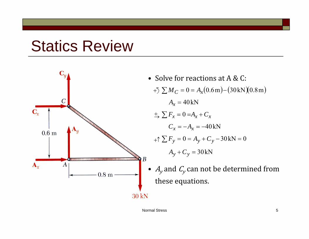
This is a structure which was designed to support a 30kN load, it consists of a boom AB and of a rod BC. The boom and rod are connected by a pin at B and are supported by pins and brackets at A and C. (1) Is there a reaction moment at A? why? (2) What is the reaction force in the vertical direction at A? (3) What is the internal force in AB? (4) What is the internal force in BC?

Two-force member
Normal Stress 3

Normal Stress 4
Statics Review
Pins norxnmoment
Normal Stress 5
Statics Review
• Ay andCy cannotbedeterminedfromtheseequations.
kN30
0kN300
kN40
0
kN40
m8.0kN30m6.00
yy
yyy
xx
xxx
x
xC
CA
CAF
AC
CAF
A
AM
• SolveforreactionsatA&C:

Normal Stress 6
Statics Review
• Results: kN30kN40kN40 yx CCA
0
m8.00
y
yB
A
AM• Considerafree‐bodydiagramfortheboom:
kN30yC
substituteintothestructureequilibriumequation
Seesection1.1intextforcompletestaticanalysisandreviewofmethodofjoints.
Bx

Normal Stress 7

Normal Stress 8
Introduction to Normal Stress

Normal Stress 9
Introduction to Normal StressStress Forceperunitarea
AF

Normal Stress 10
Ifstressvariesoveracross‐section,theresultantoftheinternalforcesforanaxiallyloadedmemberisnormal toasectioncutperpendiculartotheaxis.Thus,wecanwritethestressatapointas
WeassumetheforceFisevenlydistributedoverthecross‐sectionofthebar.InrealityF resultantforceovertheendofthebar.
Introduction to Normal Stress
AP
AF
aveA
0
lim
A
ave dAdFAP

SignconventionTensile memberisintension
Compressive memberisincompression
Units force/areaEnglish: lb/in2 psi
kip/in2 ksi
SI: N/m2 Pa PascalkN/m2 kPaMPa,GPa,etc.
Normal Stress 11
Introduction to Normal Stress
00
Tensile
Compressive

Normal Stress 12
Homogenous:materialisthesamethroughoutthebar Cross‐section:sectionperpendiculartolongitudinalaxisofbar
Prismatic:cross‐sectiondoesnotchangealongaxisofbar
Definitions and Assumptions
F’ F
A
Prismatic Non-Prismatic

Normal Stress 13
Uniaxialbar: abarwithonlyoneaxis
NormalStress σ : stressactingperpendiculartothecross‐section.
Deformationofthebarisuniformthroughout. UniformStressState
Stressismeasuredfarfromthepointofapplication.
Loadsmustactthroughthecentroid ofthecross‐section.
Definitions and Assumptions

Normal Stress 14
Theuniformstressstatedoesnotapplyneartheendsofthebar.
Assumethedistributionofnormalstressesinanaxiallyloadedmemberisuniform,exceptintheimmediatevicinityofthepointsofapplicationoftheloadsSaint‐Venant’sPrinciple .
Definitions and Assumptions
“Uniform” Stress

Introduction to Normal Stress
Normal Stress 15
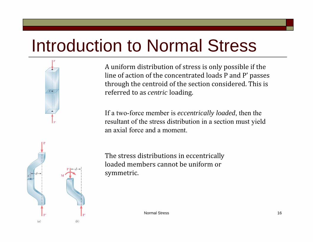
Introduction to Normal StressAuniformdistributionofstressisonlypossibleifthelineofactionoftheconcentratedloadsPandP’passesthroughthecentroidofthesectionconsidered.Thisisreferredtoascentric loading.
If a two-force member is eccentrically loaded, then the resultant of the stress distribution in a section must yield an axial force and a moment.
Normal Stress 16
Thestressdistributionsineccentricallyloadedmemberscannotbeuniformorsymmetric.

Normal Stress 17
Howdoweknowallloadsmustactthroughthecentroidofthecross‐section?
LetusrepresentP,theresultantforce,byauniformstressoverthecross‐section sothattheyarestaticallyequivalent .
Definitions and Assumptions

Normal Stress 18
Momentsduetoσ:
SetMx Mx andMy My
Definitions and Assumptions
Ay
Ax
dAxM
dAyM
AA
AA
xdAA
dAxP
x
ydAA
dAyP
y
11
11
Equationsforthecentroid
MM xx MM yy

Normal Stress 19
Example Problem Canthestructureweusedforourstaticsreviewsafelysupporta
30kNload? Assumetheentirestructureismadeofsteelwithamaximumallowablestressσall 165MPa.
Cross-section 30 mm x 50 mm

Normal Stress 20
Example Problem Twocylindricalrodsareweldedtogetherandloadedasshown.Find
thenormalstressatthemidsectionofeachrod.
mmd
mmd
30
50
2
1

Shearing and Bearing Stress 21
Shearing and Bearing Stress (1.2C-1.2E, 1.4)MAE 314 – Solid MechanicsYun Jing

Shearing and Bearing Stress 22
What is Shearing Stress?
Welearnedaboutnormalstress σ ,whichactsperpendicular tothecross‐section.
Shearstress τ actstangential tothesurfaceofamaterialelement.
Normal stress results in a volume change.
Shear stress results in a shape change.

Shearing and Bearing Stress 23
Where Do Shearing Stresses Occur? Shearingstressesarecommonlyfoundinbolts,pins,and
rivets.
Free Body Diagram of Bolt
Boltisin“single”shear
ForcePresultsinshearingstress
ForceFresultsinbearingstresswilldiscusslater

Shearing and Bearing Stress 24
Wedonot assumeτ isuniformoverthecross‐section,becausethisisnotthecase.
τ istheaverageshearstress.
Themaximumvalueofτ maybeconsiderablygreaterthanτave,whichisimportantfordesignpurposes.
Shear Stress Defined
AF
AP
ave

Shearing and Bearing Stress 25
Double Shear
Free Body Diagram of Bolt Free Body Diagram of Center of Bolt
AF
A
F
AP
ave 22
Boltisin“double”shear

Shearing and Bearing Stress 26
Bearing Stress Bearing stress is a normal stress, not a shearing stress.
Thus,
where Ab = projected area where bearing pressure is appliedP = bearing force
tdP
AP
bb
Single shear case

Would like to determine the stresses in the members and connections of the structure shown.
Must consider maximum normal stresses in AB and BC, and the shearing stress and bearing stress at each pinned connection
From a statics analysis:FAB = 40 kN (compression) FBC = 50 kN (tension)
Example

Rod & Boom Normal Stresses

Pin Shearing Stresses

Pin Shearing Stresses

Pin Bearing Stresses

Rod & Boom Normal StressesThe rod is in tension with an axial force of 50 kN.
The boom is in compression with an axial force of 40 kN and average normal stress of –26.7 MPa.
The minimum area sections at the boom ends are unstressed since the boom is in compression.
MPa167m10300
1050
m10300mm25mm40mm20
26
3,
26
NAP
A
endBC
At the flattened rod ends, the smallest cross-sectional area occurs at the pin centerline,
At the rod center, the average normal stress in the circular cross-section (A = 314x10-6m2) is BC = +159 MPa.

Pin Shearing StressesThe cross-sectional area for pins at A, B,
and C,
262
2 m104912mm25
rA
MPa102m10491N1050
26
3,
A
PaveC
The force on the pin at C is equal to the force exerted by the rod BC,
The pin at A is in double shear with a total force equal to the force exerted by the boom AB,
MPa7.40m10491
kN2026,
A
PaveA

Divide the pin at B into sections to determine the section with the largest shear force,
(largest) kN25
kN15
G
E
P
P
MPa9.50m10491
kN2526,
A
PGaveB
Evaluate the corresponding average shearing stress,
Pin Shearing Stresses

Pin Bearing Stresses
To determine the bearing stress at A in the boom AB, we have t = 30 mm and d = 25 mm,
MPa3.53mm25mm30
kN40
tdP
b
To determine the bearing stress at A in the bracket, we have t = 2(25 mm) = 50 mm and d = 25 mm,
MPa0.32mm25mm50
kN40
tdP
b

Shearing and Bearing Stress 36
Equilibrium of Shear Stresses Consideraninfinitesimalelementofmaterial.Applyasingleshear
stress,τ1.
Totalshearforceonsurfaceis τ1 bc.
Forequilibriuminthey‐direction,applyτ1 on ‐ surface.
Formomentequilibriumaboutthez‐axis,applyτ2 ontopandbottomsurfaces.
Momentequilibriumequationaboutz‐axis:
Thus,ashearstressmustbebalancedbythreeotherstressesfortheelementtobeinequilibrium.
1
2
2
1
bacabc )()( 21
21
Shearing and Bearing Stress 37
Equilibrium of Shear Stresses
1
2
2
1
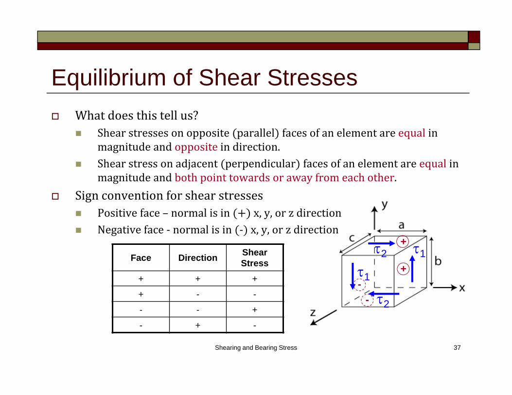
Face Direction Shear Stress
+ + +
+ - -
- - +
- + -
Whatdoesthistellus? Shearstressesonopposite parallel facesofanelementareequal in
magnitudeandopposite indirection. Shearstressonadjacent perpendicular facesofanelementareequal in
magnitudeandbothpointtowardsorawayfromeachother. Signconventionforshearstresses
Positiveface– normalisin x,y,orzdirection Negativeface‐ normalisin ‐ x,y,orzdirection
+
+-
-

Shearing and Bearing Stress 38
σx stressinx‐direction appliedintheplanenormaltox‐axis σ y stressiny‐direction appliedintheplanenormaltoy‐axis σ z stressinz‐direction appliedintheplanenormaltoz‐axis τxy stressiny‐direction appliedintheplanenormaltox‐axis τ xz stressinz‐direction appliedintheplanenormaltox‐axis τ zy stressiny‐direction appliedintheplanenormaltoz‐axis Andsoon…
Define General State of Stressy
z x

Shearing and Bearing Stress 39
Thereare9componentsofstress:σx,σ y,σ z,τxy,τ xz,τ yx,τ yz,τ zx,τ zy
Asshownpreviously,inordertomaintainequilibrium:τ xy τ yx,τ xz τ zx,τ yz τ zy
Thereareonly6independentstresscomponents.
Define General State of Stressy
z x

Shearing and Bearing Stress 40
Example Problem AloadP 10kipsisappliedtoarodsupportedasshown
byaplatewitha0.6in.diameterhole.Determinetheshearstressintherodandtheplate.

Shearing and Bearing Stress 41
Example Problem LinkABisusedtosupporttheendofahorizontalbeam.IflinkABis
subjecttoa10kipscompressiveforcedeterminethenormalandbearingstressinthelinkandtheshearstressineachofthepins.
ind
int
inb
1
41
2

Oblique Planes and Design Considerations 42
Oblique Planes and Design Considerations (1.3, 1.5)
MAE 314 – Solid MechanicsYun Jing

Oblique Planes and Design Considerations 43
Stress on an Oblique Plane Whathavewelearnedsofar?
Axialforcesinatwo‐forcemembercausenormalstresses.
Transverseforcesexertedonboltsandpinscauseshearingstresses.

Oblique Planes and Design Considerations 44
Stress on an Oblique Plane Axialforcescausebothnormalandshearingstressesonplaneswhich
arenotperpendiculartotheaxis.

Oblique Planes and Design Considerations 45
Stress on an Oblique Plane Axialforcescausebothnormalandshearingstressesonplaneswhich
arenotperpendiculartotheaxis.
Consideraninclinedsectionofauniaxialbar.
TheresultantforceintheaxialdirectionmustequalPtosatisfyequilibrium.
Theforcecanberesolvedintocomponentsperpendiculartothesection,F,andparalleltothesection,V.
TheareaofthesectioniscosPF sinPV
cos/cos 00 AAAA

Oblique Planes and Design Considerations 46
Stress on an Oblique Plane Wecanformulatetheaveragenormalstressonthesectionas
Theaverageshearstressonthesectionis
Thus,anormal force appliedtoabaronaninclinedsectionproducesacombinationofshear andnormalstresses.
2
00
coscos/
cosAP
AP
AF
cossincos/
sin
00 AP
AP
AV

Oblique Planes and Design Considerations 47
Stress on an Oblique Plane Sinceσ andτ arefunctionsofsineandcosine,weknowthe
maximumandminimumvalueswilloccuratθ 00,450,and900.
At θ=±900 σ=0
At θ=±450 σ=P/2A0
At θ=00 σ=P/A0 (max)
At θ=±900 τ=0
At θ=±450 τ=P/2A0 (max)
At θ=00 τ=0
2
0
cosAP
cossin0A
P

Oblique Planes and Design Considerations
Stress on an Oblique Plane Whatdoesthismeaninreality?

Oblique Planes and Design Considerations 49
Design Considerations Fromadesignperspective,itisimportanttoknowthe
largestloadwhichamaterialcanholdbeforefailing.
Thisloadiscalledtheultimateload,Pu.
Ultimatenormalstressisdenotedasσu andultimateshearstressisdenotedasτu.
APu
u
APu
u

Oblique Planes and Design Considerations 50
Design Considerations Often the allowable load is considerably smaller than the
ultimate load.
It is a common design practice to use factor of safety.
all
u
PP
loadallowableloadultimate
SF ..
all
u
stressallowablestressultimate
SF
..all
u
stressallowablestressultimate
SF
..

Oblique Planes and Design Considerations 51
Example Problem Twowoodenmembersaresplicedasshown.Ifthemaximum
allowabletensilestressinthespliceis75psi,determinethelargestloadthatcanbesafelysupportedandtheshearingstressinthesplice.

Oblique Planes and Design Considerations 52
Example Problem Aloadissupportedbyasteelpininsertedintoahanging
woodenpiece.Giventheinformationbelow,determinetheloadPifanoverallfactorofsafetyof3.2isdesired.
mmd
mmc
mmb
MPa
MPa
tensioninMPa
steelu
woodu
woodu
12
55
40
145
5.7
)(60
_
_
_