Embed Size (px)
Citation preview
CHAPTER
3Virtual Machines and Virtualizationof Clusters and Data Centers
CHAPTER OUTLINE
Summary . . . . . . . . . . . . . . . . . . . . . . . . . . . . . . . . . . . . . . . . . . . . . . . . . . . . . . . . . . . . . . . . . . . . . . . . . . . . . . . . . . . . . . . . . . . 1303.1 Implementation Levels of Virtualization . . . . . . . . . . . . . . . . . . . . . . . . . . . . . . . . . . . . . . . . . . . . . . . . . . . . . . . . . . 130
3.1.1 Levels of Virtualization Implementation. . . . . . . . . . . . . . . . . . . . . . . . . . . . . . . . . . . . . . . . . . . . . . 1303.1.2 VMM Design Requirements and Providers . . . . . . . . . . . . . . . . . . . . . . . . . . . . . . . . . . . . . . . . . . . . 1333.1.3 Virtualization Support at the OS Level . . . . . . . . . . . . . . . . . . . . . . . . . . . . . . . . . . . . . . . . . . . . . . . 1353.1.4 Middleware Support for Virtualization. . . . . . . . . . . . . . . . . . . . . . . . . . . . . . . . . . . . . . . . . . . . . . . . 138
3.2 Virtualization Structures/Tools and Mechanisms . . . . . . . . . . . . . . . . . . . . . . . . . . . . . . . . . . . . . . . . . . . . . . . . . . 1403.2.1 Hypervisor and Xen Architecture . . . . . . . . . . . . . . . . . . . . . . . . . . . . . . . . . . . . . . . . . . . . . . . . . . . . 1403.2.2 Binary Translation with Full Virtualization. . . . . . . . . . . . . . . . . . . . . . . . . . . . . . . . . . . . . . . . . . . . 1413.2.3 Para-Virtualization with Compiler Support . . . . . . . . . . . . . . . . . . . . . . . . . . . . . . . . . . . . . . . . . . . . 143
3.3 Virtualization of CPU, Memory, and I/O Devices . . . . . . . . . . . . . . . . . . . . . . . . . . . . . . . . . . . . . . . . . . . . . . . . . . 1453.3.1 Hardware Support for Virtualization. . . . . . . . . . . . . . . . . . . . . . . . . . . . . . . . . . . . . . . . . . . . . . . . . 1453.3.2 CPU Virtualization . . . . . . . . . . . . . . . . . . . . . . . . . . . . . . . . . . . . . . . . . . . . . . . . . . . . . . . . . . . . . . . . . 1473.3.3 Memory Virtualization . . . . . . . . . . . . . . . . . . . . . . . . . . . . . . . . . . . . . . . . . . . . . . . . . . . . . . . . . . . . . . 1483.3.4 I/O Virtualization. . . . . . . . . . . . . . . . . . . . . . . . . . . . . . . . . . . . . . . . . . . . . . . . . . . . . . . . . . . . . . . . . . . 1503.3.5 Virtualization in Multi-Core Processors . . . . . . . . . . . . . . . . . . . . . . . . . . . . . . . . . . . . . . . . . . . . . . . 153
3.4 Virtual Clusters and Resource Management . . . . . . . . . . . . . . . . . . . . . . . . . . . . . . . . . . . . . . . . . . . . . . . . . . . . . . 1553.4.1 Physical versus Virtual Clusters . . . . . . . . . . . . . . . . . . . . . . . . . . . . . . . . . . . . . . . . . . . . . . . . . . . . . 1563.4.2 Live VM Migration Steps and Performance Effects . . . . . . . . . . . . . . . . . . . . . . . . . . . . . . . . . . . . 1593.4.3 Migration of Memory, Files, and Network Resources. . . . . . . . . . . . . . . . . . . . . . . . . . . . . . . . . . 1623.4.4 Dynamic Deployment of Virtual Clusters . . . . . . . . . . . . . . . . . . . . . . . . . . . . . . . . . . . . . . . . . . . . . 165
3.5 Virtualization for Data-Center Automation . . . . . . . . . . . . . . . . . . . . . . . . . . . . . . . . . . . . . . . . . . . . . . . . . . . . . . . . 1693.5.1 Server Consolidation in Data Centers . . . . . . . . . . . . . . . . . . . . . . . . . . . . . . . . . . . . . . . . . . . . . . . . 1693.5.2 Virtual Storage Management . . . . . . . . . . . . . . . . . . . . . . . . . . . . . . . . . . . . . . . . . . . . . . . . . . . . . . . . 1713.5.3 Cloud OS for Virtualized Data Centers . . . . . . . . . . . . . . . . . . . . . . . . . . . . . . . . . . . . . . . . . . . . . . . 1723.5.4 Trust Management in Virtualized Data Centers . . . . . . . . . . . . . . . . . . . . . . . . . . . . . . . . . . . . . . . 176
3.6 Bibliographic Notes and Homework Problems. . . . . . . . . . . . . . . . . . . . . . . . . . . . . . . . . . . . . . . . . . . . . . . . . . . . 179Acknowledgments . . . . . . . . . . . . . . . . . . . . . . . . . . . . . . . . . . . . . . . . . . . . . . . . . . . . . . . . . . . . . . . . . . . . . . . . . . . . . . . . . . 179References . . . . . . . . . . . . . . . . . . . . . . . . . . . . . . . . . . . . . . . . . . . . . . . . . . . . . . . . . . . . . . . . . . . . . . . . . . . . . . . . . . . . . . . . . 180Homework Problems. . . . . . . . . . . . . . . . . . . . . . . . . . . . . . . . . . . . . . . . . . . . . . . . . . . . . . . . . . . . . . . . . . . . . . . . . . . . . . . . 183
Distributed and Cloud Computing© 2012 Elsevier, Inc. All rights reserved.
129
SUMMARYThe reincarnation of virtual machines (VMs) presents a great opportunity for parallel, cluster, grid,cloud, and distributed computing. Virtualization technology benefits the computer and IT industriesby enabling users to share expensive hardware resources by multiplexing VMs on the same set ofhardware hosts. This chapter covers virtualization levels, VM architectures, virtual networking,virtual cluster construction, and virtualized data-center design and automation in cloud computing.In particular, the designs of dynamically structured clusters, grids, and clouds are presented withVMs and virtual clusters.
3.1 IMPLEMENTATION LEVELS OF VIRTUALIZATIONVirtualization is a computer architecture technology by which multiple virtual machines (VMs) aremultiplexed in the same hardware machine. The idea of VMs can be dated back to the 1960s [53].The purpose of a VM is to enhance resource sharing by many users and improve computer perfor-mance in terms of resource utilization and application flexibility. Hardware resources (CPU, mem-ory, I/O devices, etc.) or software resources (operating system and software libraries) can bevirtualized in various functional layers. This virtualization technology has been revitalized as thedemand for distributed and cloud computing increased sharply in recent years [41].
The idea is to separate the hardware from the software to yield better system efficiency. Forexample, computer users gained access to much enlarged memory space when the concept of virtualmemory was introduced. Similarly, virtualization techniques can be applied to enhance the use ofcompute engines, networks, and storage. In this chapter we will discuss VMs and their applicationsfor building distributed systems. According to a 2009 Gartner Report, virtualization was the topstrategic technology poised to change the computer industry. With sufficient storage, any computerplatform can be installed in another host computer, even if they use processors with differentinstruction sets and run with distinct operating systems on the same hardware.
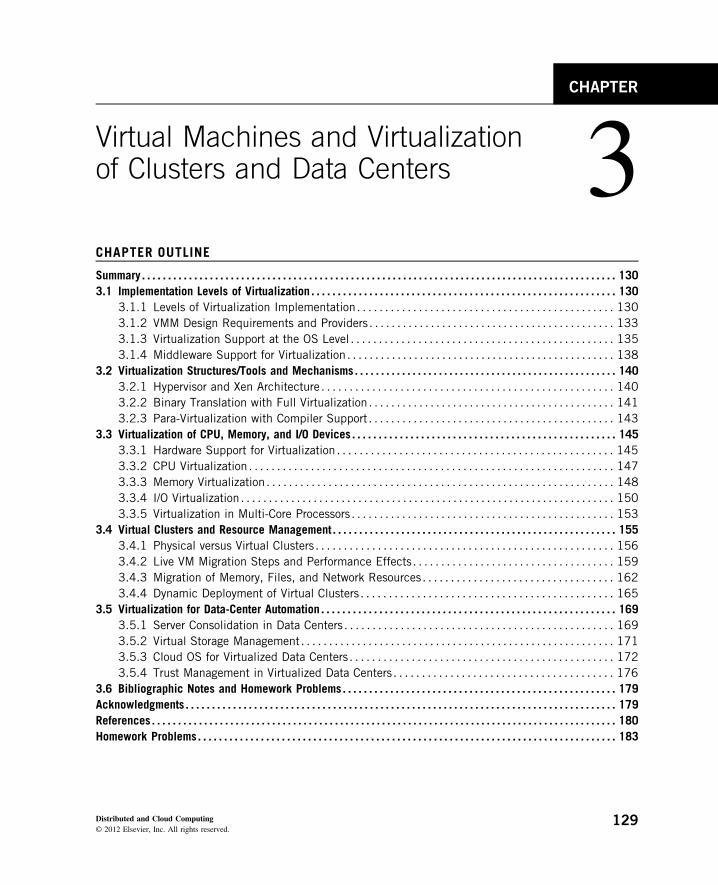
3.1.1 Levels of Virtualization ImplementationA traditional computer runs with a host operating system specially tailored for its hardware architec-ture, as shown in Figure 3.1(a). After virtualization, different user applications managed by theirown operating systems (guest OS) can run on the same hardware, independent of the host OS. Thisis often done by adding additional software, called a virtualization layer as shown in Figure 3.1(b).This virtualization layer is known as hypervisor or virtual machine monitor (VMM) [54]. The VMsare shown in the upper boxes, where applications run with their own guest OS over the virtualizedCPU, memory, and I/O resources.
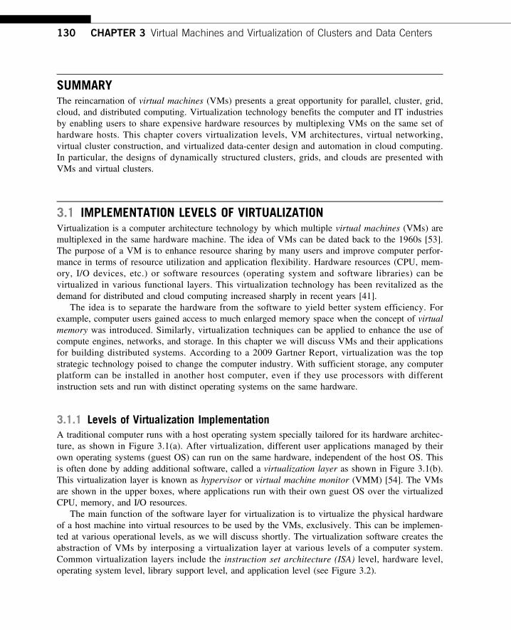
The main function of the software layer for virtualization is to virtualize the physical hardwareof a host machine into virtual resources to be used by the VMs, exclusively. This can be implemen-ted at various operational levels, as we will discuss shortly. The virtualization software creates theabstraction of VMs by interposing a virtualization layer at various levels of a computer system.Common virtualization layers include the instruction set architecture (ISA) level, hardware level,operating system level, library support level, and application level (see Figure 3.2).
130 CHAPTER 3 Virtual Machines and Virtualization of Clusters and Data Centers
Application level
JVM / .NET CLR / Panot
WINE/ WABI/ LxRun / Visual MainWin / vCUDA
Jail / Virtual Environment / Ensim’s VPS / FVM
VMware / Virtual PC / Denali / Xen / L4 /Plex 86 / User mode Linux / Cooperative Linux
Bochs / Crusoe / QEMU / BIRD / Dynamo
Operating system level
Library (user-level API) level
Hardware abstraction layer (HAL) level
Instruction set architecture (ISA) level
FIGURE 3.2
Virtualization ranging from hardware to applications in five abstraction levels.
Application
Host operating system
Hardware
Hardware running the Host OS
(a) Traditional computer (b) After virtualization
Application
Guest OS
Application
Guest OS Virt
ual
Mac
hine
s
Virtualization layer (Hypervisor or VMM)
FIGURE 3.1
The architecture of a computer system before and after virtualization, where VMM stands for virtual machinemonitor.
3.1 Implementation Levels of Virtualization 131
3.1.1.1 Instruction Set Architecture LevelAt the ISA level, virtualization is performed by emulating a given ISA by the ISA of the hostmachine. For example, MIPS binary code can run on an x86-based host machine with the help ofISA emulation. With this approach, it is possible to run a large amount of legacy binary code writ-ten for various processors on any given new hardware host machine. Instruction set emulation leadsto virtual ISAs created on any hardware machine.
The basic emulation method is through code interpretation. An interpreter program interprets thesource instructions to target instructions one by one. One source instruction may require tens orhundreds of native target instructions to perform its function. Obviously, this process is relativelyslow. For better performance, dynamic binary translation is desired. This approach translates basicblocks of dynamic source instructions to target instructions. The basic blocks can also be extendedto program traces or super blocks to increase translation efficiency. Instruction set emulationrequires binary translation and optimization. A virtual instruction set architecture (V-ISA) thusrequires adding a processor-specific software translation layer to the compiler.
3.1.1.2 Hardware Abstraction LevelHardware-level virtualization is performed right on top of the bare hardware. On the one hand, thisapproach generates a virtual hardware environment for a VM. On the other hand, the process managesthe underlying hardware through virtualization. The idea is to virtualize a computer’s resources, such asits processors, memory, and I/O devices. The intention is to upgrade the hardware utilization rate bymultiple users concurrently. The idea was implemented in the IBM VM/370 in the 1960s. Morerecently, the Xen hypervisor has been applied to virtualize x86-based machines to run Linux or otherguest OS applications. We will discuss hardware virtualization approaches in more detail in Section 3.3.
3.1.1.3 Operating System LevelThis refers to an abstraction layer between traditional OS and user applications. OS-level virtualiza-tion creates isolated containers on a single physical server and the OS instances to utilize the hard-ware and software in data centers. The containers behave like real servers. OS-level virtualization iscommonly used in creating virtual hosting environments to allocate hardware resources among alarge number of mutually distrusting users. It is also used, to a lesser extent, in consolidating serverhardware by moving services on separate hosts into containers or VMs on one server. OS-levelvirtualization is depicted in Section 3.1.3.
3.1.1.4 Library Support LevelMost applications use APIs exported by user-level libraries rather than using lengthy system callsby the OS. Since most systems provide well-documented APIs, such an interface becomes anothercandidate for virtualization. Virtualization with library interfaces is possible by controlling the com-munication link between applications and the rest of a system through API hooks. The softwaretool WINE has implemented this approach to support Windows applications on top of UNIX hosts.Another example is the vCUDA which allows applications executing within VMs to leverage GPUhardware acceleration. This approach is detailed in Section 3.1.4.
3.1.1.5 User-Application LevelVirtualization at the application level virtualizes an application as a VM. On a traditional OS, anapplication often runs as a process. Therefore, application-level virtualization is also known as
132 CHAPTER 3 Virtual Machines and Virtualization of Clusters and Data Centers
process-level virtualization. The most popular approach is to deploy high level language (HLL)VMs. In this scenario, the virtualization layer sits as an application program on top of the operatingsystem, and the layer exports an abstraction of a VM that can run programs written and compiledto a particular abstract machine definition. Any program written in the HLL and compiled for thisVM will be able to run on it. The Microsoft .NET CLR and Java Virtual Machine (JVM) are twogood examples of this class of VM.
Other forms of application-level virtualization are known as application isolation, applicationsandboxing, or application streaming. The process involves wrapping the application in a layer thatis isolated from the host OS and other applications. The result is an application that is much easierto distribute and remove from user workstations. An example is the LANDesk application virtuali-zation platform which deploys software applications as self-contained, executable files in an isolatedenvironment without requiring installation, system modifications, or elevated security privileges.
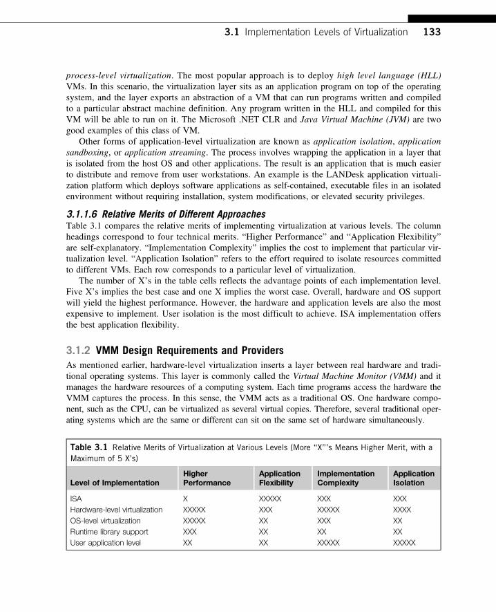
3.1.1.6 Relative Merits of Different ApproachesTable 3.1 compares the relative merits of implementing virtualization at various levels. The columnheadings correspond to four technical merits. “Higher Performance” and “Application Flexibility”are self-explanatory. “Implementation Complexity” implies the cost to implement that particular vir-tualization level. “Application Isolation” refers to the effort required to isolate resources committedto different VMs. Each row corresponds to a particular level of virtualization.
The number of X’s in the table cells reflects the advantage points of each implementation level.Five X’s implies the best case and one X implies the worst case. Overall, hardware and OS supportwill yield the highest performance. However, the hardware and application levels are also the mostexpensive to implement. User isolation is the most difficult to achieve. ISA implementation offersthe best application flexibility.
3.1.2 VMM Design Requirements and ProvidersAs mentioned earlier, hardware-level virtualization inserts a layer between real hardware and tradi-tional operating systems. This layer is commonly called the Virtual Machine Monitor (VMM) and itmanages the hardware resources of a computing system. Each time programs access the hardware theVMM captures the process. In this sense, the VMM acts as a traditional OS. One hardware compo-nent, such as the CPU, can be virtualized as several virtual copies. Therefore, several traditional oper-ating systems which are the same or different can sit on the same set of hardware simultaneously.
Table 3.1 Relative Merits of Virtualization at Various Levels (More “X”’s Means Higher Merit, with aMaximum of 5 X’s)
Level of ImplementationHigherPerformance
ApplicationFlexibility
ImplementationComplexity
ApplicationIsolation
ISA X XXXXX XXX XXXHardware-level virtualization XXXXX XXX XXXXX XXXXOS-level virtualization XXXXX XX XXX XXRuntime library support XXX XX XX XXUser application level XX XX XXXXX XXXXX
3.1 Implementation Levels of Virtualization 133
There are three requirements for a VMM. First, a VMM should provide an environment for pro-grams which is essentially identical to the original machine. Second, programs run in this environ-ment should show, at worst, only minor decreases in speed. Third, a VMM should be in completecontrol of the system resources. Any program run under a VMM should exhibit a function identicalto that which it runs on the original machine directly. Two possible exceptions in terms of differ-ences are permitted with this requirement: differences caused by the availability of system resourcesand differences caused by timing dependencies. The former arises when more than one VM is run-ning on the same machine.
The hardware resource requirements, such as memory, of each VM are reduced, but the sum ofthem is greater than that of the real machine installed. The latter qualification is required because ofthe intervening level of software and the effect of any other VMs concurrently existing on the samehardware. Obviously, these two differences pertain to performance, while the function a VMM pro-vides stays the same as that of a real machine. However, the identical environment requirementexcludes the behavior of the usual time-sharing operating system from being classed as a VMM.
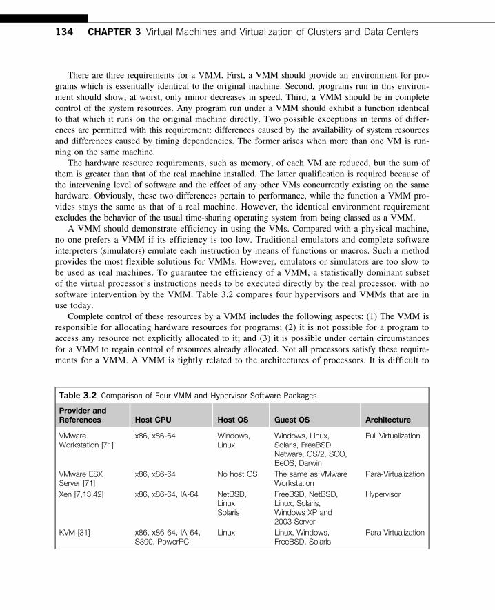
A VMM should demonstrate efficiency in using the VMs. Compared with a physical machine,no one prefers a VMM if its efficiency is too low. Traditional emulators and complete softwareinterpreters (simulators) emulate each instruction by means of functions or macros. Such a methodprovides the most flexible solutions for VMMs. However, emulators or simulators are too slow tobe used as real machines. To guarantee the efficiency of a VMM, a statistically dominant subsetof the virtual processor’s instructions needs to be executed directly by the real processor, with nosoftware intervention by the VMM. Table 3.2 compares four hypervisors and VMMs that are inuse today.
Complete control of these resources by a VMM includes the following aspects: (1) The VMM isresponsible for allocating hardware resources for programs; (2) it is not possible for a program toaccess any resource not explicitly allocated to it; and (3) it is possible under certain circumstancesfor a VMM to regain control of resources already allocated. Not all processors satisfy these require-ments for a VMM. A VMM is tightly related to the architectures of processors. It is difficult to
Table 3.2 Comparison of Four VMM and Hypervisor Software Packages
Provider andReferences Host CPU Host OS Guest OS Architecture
VMwareWorkstation [71]
x86, x86-64 Windows,Linux
Windows, Linux,Solaris, FreeBSD,Netware, OS/2, SCO,BeOS, Darwin
Full Virtualization
VMware ESXServer [71]
x86, x86-64 No host OS The same as VMwareWorkstation
Para-Virtualization
Xen [7,13,42] x86, x86-64, IA-64 NetBSD,Linux,Solaris
FreeBSD, NetBSD,Linux, Solaris,Windows XP and2003 Server
Hypervisor
KVM [31] x86, x86-64, IA-64,S390, PowerPC
Linux Linux, Windows,FreeBSD, Solaris
Para-Virtualization
134 CHAPTER 3 Virtual Machines and Virtualization of Clusters and Data Centers
implement a VMM for some types of processors, such as the x86. Specific limitations include theinability to trap on some privileged instructions. If a processor is not designed to support virtualiza-tion primarily, it is necessary to modify the hardware to satisfy the three requirements for a VMM.This is known as hardware-assisted virtualization.
3.1.3 Virtualization Support at the OS LevelWith the help of VM technology, a new computing mode known as cloud computing is emerging.Cloud computing is transforming the computing landscape by shifting the hardware and staffing costsof managing a computational center to third parties, just like banks. However, cloud computing has atleast two challenges. The first is the ability to use a variable number of physical machines and VMinstances depending on the needs of a problem. For example, a task may need only a single CPU dur-ing some phases of execution but may need hundreds of CPUs at other times. The second challengeconcerns the slow operation of instantiating new VMs. Currently, new VMs originate either as freshboots or as replicates of a template VM, unaware of the current application state. Therefore, to bettersupport cloud computing, a large amount of research and development should be done.
3.1.3.1 Why OS-Level Virtualization?As mentioned earlier, it is slow to initialize a hardware-level VM because each VM creates its ownimage from scratch. In a cloud computing environment, perhaps thousands of VMs need to be initi-alized simultaneously. Besides slow operation, storing the VM images also becomes an issue. As amatter of fact, there is considerable repeated content among VM images. Moreover, full virtualiza-tion at the hardware level also has the disadvantages of slow performance and low density, and theneed for para-virtualization to modify the guest OS. To reduce the performance overhead ofhardware-level virtualization, even hardware modification is needed. OS-level virtualization providesa feasible solution for these hardware-level virtualization issues.
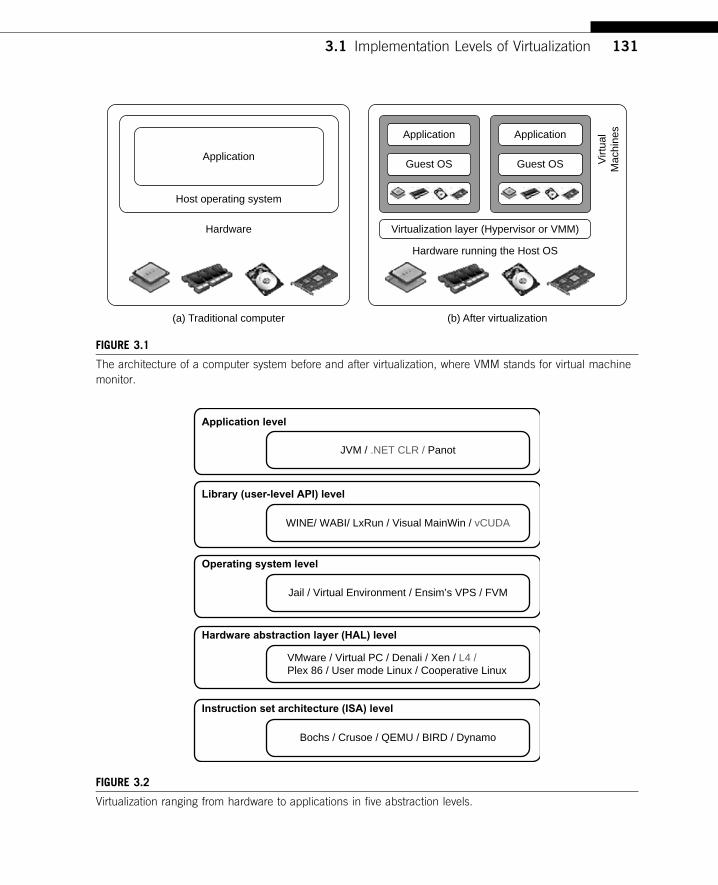
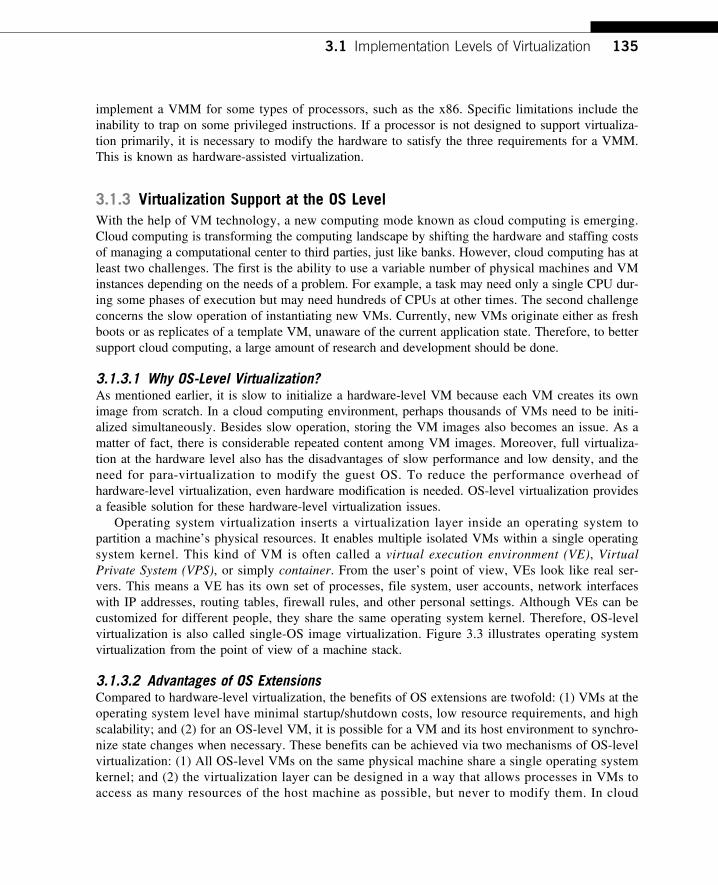
Operating system virtualization inserts a virtualization layer inside an operating system topartition a machine’s physical resources. It enables multiple isolated VMs within a single operatingsystem kernel. This kind of VM is often called a virtual execution environment (VE), VirtualPrivate System (VPS), or simply container. From the user’s point of view, VEs look like real ser-vers. This means a VE has its own set of processes, file system, user accounts, network interfaceswith IP addresses, routing tables, firewall rules, and other personal settings. Although VEs can becustomized for different people, they share the same operating system kernel. Therefore, OS-levelvirtualization is also called single-OS image virtualization. Figure 3.3 illustrates operating systemvirtualization from the point of view of a machine stack.
3.1.3.2 Advantages of OS ExtensionsCompared to hardware-level virtualization, the benefits of OS extensions are twofold: (1) VMs at theoperating system level have minimal startup/shutdown costs, low resource requirements, and highscalability; and (2) for an OS-level VM, it is possible for a VM and its host environment to synchro-nize state changes when necessary. These benefits can be achieved via two mechanisms of OS-levelvirtualization: (1) All OS-level VMs on the same physical machine share a single operating systemkernel; and (2) the virtualization layer can be designed in a way that allows processes in VMs toaccess as many resources of the host machine as possible, but never to modify them. In cloud
3.1 Implementation Levels of Virtualization 135
computing, the first and second benefits can be used to overcome the defects of slow initialization ofVMs at the hardware level, and being unaware of the current application state, respectively.
3.1.3.3 Disadvantages of OS ExtensionsThe main disadvantage of OS extensions is that all the VMs at operating system level on a singlecontainer must have the same kind of guest operating system. That is, although different OS-levelVMs may have different operating system distributions, they must pertain to the same operatingsystem family. For example, a Windows distribution such as Windows XP cannot run on aLinux-based container. However, users of cloud computing have various preferences. Some preferWindows and others prefer Linux or other operating systems. Therefore, there is a challenge forOS-level virtualization in such cases.
Figure 3.3 illustrates the concept of OS-level virtualization. The virtualization layer is insertedinside the OS to partition the hardware resources for multiple VMs to run their applications inmultiple virtual environments. To implement OS-level virtualization, isolated execution environ-ments (VMs) should be created based on a single OS kernel. Furthermore, the access requests froma VM need to be redirected to the VM’s local resource partition on the physical machine. For
Phy
sica
l ser
ver
(Har
dwar
e no
de)
#3
root
user
user
ApplicationsoftwareV
irtua
l priv
ate
serv
er
root
user
user
Applicationsoftware
Virt
ual p
rivat
e se
rver
root
user
user
ApplicationsoftwareV
irtua
l priv
ate
serv
er
Network
Hardware
Host operating system
OpenVZ layer
OpenVZ templates
Network
Hardware
Host operating system
OpenVZ layer
OpenVZ templates
Phy
sica
l ser
ver
(Har
dwar
e no
de)
#1
Virt
ual p
rivat
e se
rver root
user
user
Applicationsoftware
root
user
user
ApplicationsoftwareV
irtua
l priv
ate
serv
er
Phy
sica
l ser
ver
(Har
dwar
e no
de)
#2
Network
Hardware
Host operating system
OpenVZ layer
OpenVZ templates
Phy
sica
l ser
ver
(Har
dwar
e no
de)
#1
Virt
ual p
rivat
e se
rver root
user
user
Applicationsoftware
root
user
user
ApplicationsoftwareV
irtua
l priv
ate
serv
er
FIGURE 3.3
The OpenVZ virtualization layer inside the host OS, which provides some OS images to create VMs quickly.(Courtesy of OpenVZ User’s Guide [65] )
136 CHAPTER 3 Virtual Machines and Virtualization of Clusters and Data Centers
example, the chroot command in a UNIX system can create several virtual root directories within ahost OS. These virtual root directories are the root directories of all VMs created.
There are two ways to implement virtual root directories: duplicating common resources to eachVM partition; or sharing most resources with the host environment and only creating privateresource copies on the VM on demand. The first way incurs significant resource costs and overheadon a physical machine. This issue neutralizes the benefits of OS-level virtualization, compared withhardware-assisted virtualization. Therefore, OS-level virtualization is often a second choice.
3.1.3.4 Virtualization on Linux or Windows PlatformsBy far, most reported OS-level virtualization systems are Linux-based. Virtualization support on theWindows-based platform is still in the research stage. The Linux kernel offers an abstraction layerto allow software processes to work with and operate on resources without knowing the hardwaredetails. New hardware may need a new Linux kernel to support. Therefore, different Linux plat-forms use patched kernels to provide special support for extended functionality.
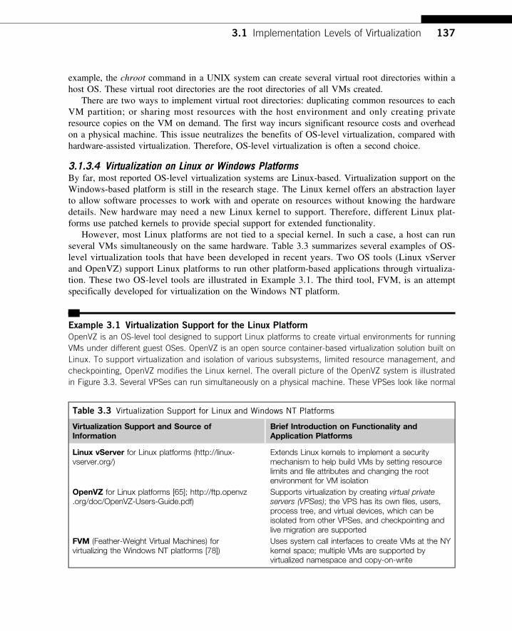
However, most Linux platforms are not tied to a special kernel. In such a case, a host can runseveral VMs simultaneously on the same hardware. Table 3.3 summarizes several examples of OS-level virtualization tools that have been developed in recent years. Two OS tools (Linux vServerand OpenVZ) support Linux platforms to run other platform-based applications through virtualiza-tion. These two OS-level tools are illustrated in Example 3.1. The third tool, FVM, is an attemptspecifically developed for virtualization on the Windows NT platform.
Example 3.1 Virtualization Support for the Linux Platform
OpenVZ is an OS-level tool designed to support Linux platforms to create virtual environments for runningVMs under different guest OSes. OpenVZ is an open source container-based virtualization solution built onLinux. To support virtualization and isolation of various subsystems, limited resource management, andcheckpointing, OpenVZ modifies the Linux kernel. The overall picture of the OpenVZ system is illustratedin Figure 3.3. Several VPSes can run simultaneously on a physical machine. These VPSes look like normal
Table 3.3 Virtualization Support for Linux and Windows NT Platforms
Virtualization Support and Source ofInformation
Brief Introduction on Functionality andApplication Platforms
Linux vServer for Linux platforms (http://linux-vserver.org/)
Extends Linux kernels to implement a securitymechanism to help build VMs by setting resourcelimits and file attributes and changing the rootenvironment for VM isolation
OpenVZ for Linux platforms [65]; http://ftp.openvz.org/doc/OpenVZ-Users-Guide.pdf)
Supports virtualization by creating virtual privateservers (VPSes); the VPS has its own files, users,process tree, and virtual devices, which can beisolated from other VPSes, and checkpointing andlive migration are supported
FVM (Feather-Weight Virtual Machines) forvirtualizing the Windows NT platforms [78])
Uses system call interfaces to create VMs at the NYkernel space; multiple VMs are supported byvirtualized namespace and copy-on-write
3.1 Implementation Levels of Virtualization 137
Linux servers. Each VPS has its own files, users and groups, process tree, virtual network, virtual devices,and IPC through semaphores and messages.
The resource management subsystem of OpenVZ consists of three components: two-level disk alloca-tion, a two-level CPU scheduler, and a resource controller. The amount of disk space a VM can use is setby the OpenVZ server administrator. This is the first level of disk allocation. Each VM acts as a standardLinux system. Hence, the VM administrator is responsible for allocating disk space for each user andgroup. This is the second-level disk quota. The first-level CPU scheduler of OpenVZ decides which VM togive the time slice to, taking into account the virtual CPU priority and limit settings.
The second-level CPU scheduler is the same as that of Linux. OpenVZ has a set of about 20 parameterswhich are carefully chosen to cover all aspects of VM operation. Therefore, the resources that a VM can useare well controlled. OpenVZ also supports checkpointing and live migration. The complete state of a VM canquickly be saved to a disk file. This file can then be transferred to another physical machine and the VM canbe restored there. It only takes a few seconds to complete the whole process. However, there is still a delayin processing because the established network connections are also migrated.
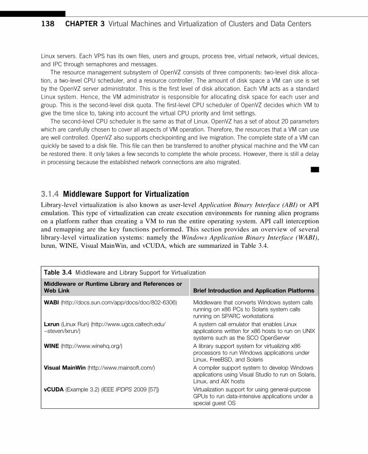
3.1.4 Middleware Support for VirtualizationLibrary-level virtualization is also known as user-level Application Binary Interface (ABI) or APIemulation. This type of virtualization can create execution environments for running alien programson a platform rather than creating a VM to run the entire operating system. API call interceptionand remapping are the key functions performed. This section provides an overview of severallibrary-level virtualization systems: namely the Windows Application Binary Interface (WABI),lxrun, WINE, Visual MainWin, and vCUDA, which are summarized in Table 3.4.
Table 3.4 Middleware and Library Support for Virtualization
Middleware or Runtime Library and References orWeb Link Brief Introduction and Application Platforms
WABI (http://docs.sun.com/app/docs/doc/802-6306) Middleware that converts Windows system callsrunning on x86 PCs to Solaris system callsrunning on SPARC workstations
Lxrun (Linux Run) (http://www.ugcs.caltech.edu/~steven/lxrun/)
A system call emulator that enables Linuxapplications written for x86 hosts to run on UNIXsystems such as the SCO OpenServer
WINE (http://www.winehq.org/) A library support system for virtualizing x86processors to run Windows applications underLinux, FreeBSD, and Solaris
Visual MainWin (http://www.mainsoft.com/) A compiler support system to develop Windowsapplications using Visual Studio to run on Solaris,Linux, and AIX hosts
vCUDA (Example 3.2) (IEEE IPDPS 2009 [57]) Virtualization support for using general-purposeGPUs to run data-intensive applications under aspecial guest OS
138 CHAPTER 3 Virtual Machines and Virtualization of Clusters and Data Centers
The WABI offers middleware to convert Windows system calls to Solaris system calls. Lxrun isreally a system call emulator that enables Linux applications written for x86 hosts to run on UNIXsystems. Similarly, Wine offers library support for virtualizing x86 processors to run Windows appli-cations on UNIX hosts. Visual MainWin offers a compiler support system to develop Windows appli-cations using Visual Studio to run on some UNIX hosts. The vCUDA is explained in Example 3.2with a graphical illustration in Figure 3.4.
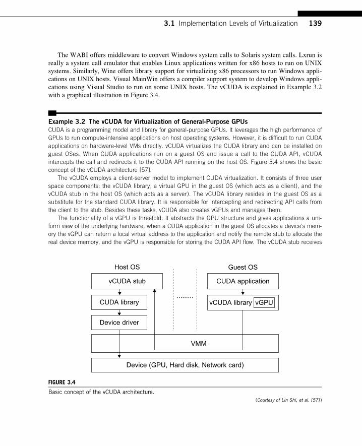
Example 3.2 The vCUDA for Virtualization of General-Purpose GPUs
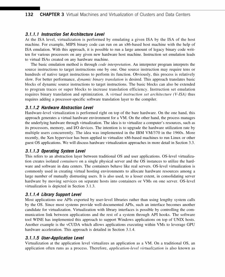
CUDA is a programming model and library for general-purpose GPUs. It leverages the high performance ofGPUs to run compute-intensive applications on host operating systems. However, it is difficult to run CUDAapplications on hardware-level VMs directly. vCUDA virtualizes the CUDA library and can be installed onguest OSes. When CUDA applications run on a guest OS and issue a call to the CUDA API, vCUDAintercepts the call and redirects it to the CUDA API running on the host OS. Figure 3.4 shows the basicconcept of the vCUDA architecture [57].
The vCUDA employs a client-server model to implement CUDA virtualization. It consists of three userspace components: the vCUDA library, a virtual GPU in the guest OS (which acts as a client), and thevCUDA stub in the host OS (which acts as a server). The vCUDA library resides in the guest OS as asubstitute for the standard CUDA library. It is responsible for intercepting and redirecting API calls fromthe client to the stub. Besides these tasks, vCUDA also creates vGPUs and manages them.
The functionality of a vGPU is threefold: It abstracts the GPU structure and gives applications a uni-form view of the underlying hardware; when a CUDA application in the guest OS allocates a device’s mem-ory the vGPU can return a local virtual address to the application and notify the remote stub to allocate thereal device memory, and the vGPU is responsible for storing the CUDA API flow. The vCUDA stub receives
Host OS Guest OS
vCUDA stub CUDA application
vCUDA library vGPUCUDA library
Device driver
VMM
Device (GPU, Hard disk, Network card)
.........
FIGURE 3.4
Basic concept of the vCUDA architecture.(Courtesy of Lin Shi, et al. [57] )
3.1 Implementation Levels of Virtualization 139
and interprets remote requests and creates a corresponding execution context for the API calls from theguest OS, then returns the results to the guest OS. The vCUDA stub also manages actual physical resourceallocation.
3.2 VIRTUALIZATION STRUCTURES/TOOLS AND MECHANISMSIn general, there are three typical classes of VM architecture. Figure 3.1 showed the architectures ofa machine before and after virtualization. Before virtualization, the operating system manages thehardware. After virtualization, a virtualization layer is inserted between the hardware and the operat-ing system. In such a case, the virtualization layer is responsible for converting portions of the realhardware into virtual hardware. Therefore, different operating systems such as Linux and Windowscan run on the same physical machine, simultaneously. Depending on the position of the virtualiza-tion layer, there are several classes of VM architectures, namely the hypervisor architecture, para-virtualization, and host-based virtualization. The hypervisor is also known as the VMM (VirtualMachine Monitor). They both perform the same virtualization operations.
3.2.1 Hypervisor and Xen ArchitectureThe hypervisor supports hardware-level virtualization (see Figure 3.1(b)) on bare metal devices likeCPU, memory, disk and network interfaces. The hypervisor software sits directly between the physi-cal hardware and its OS. This virtualization layer is referred to as either the VMM or the hypervisor.The hypervisor provides hypercalls for the guest OSes and applications. Depending on the functional-ity, a hypervisor can assume a micro-kernel architecture like the Microsoft Hyper-V. Or it canassume a monolithic hypervisor architecture like the VMware ESX for server virtualization.
A micro-kernel hypervisor includes only the basic and unchanging functions (such as physicalmemory management and processor scheduling). The device drivers and other changeable componentsare outside the hypervisor. A monolithic hypervisor implements all the aforementioned functions,including those of the device drivers. Therefore, the size of the hypervisor code of a micro-kernel hyper-visor is smaller than that of a monolithic hypervisor. Essentially, a hypervisor must be able to convertphysical devices into virtual resources dedicated for the deployed VM to use.
3.2.1.1 The Xen ArchitectureXen is an open source hypervisor program developed by Cambridge University. Xen is a micro-kernel hypervisor, which separates the policy from the mechanism. The Xen hypervisor implementsall the mechanisms, leaving the policy to be handled by Domain 0, as shown in Figure 3.5. Xendoes not include any device drivers natively [7]. It just provides a mechanism by which a guest OScan have direct access to the physical devices. As a result, the size of the Xen hypervisor is keptrather small. Xen provides a virtual environment located between the hardware and the OS.A number of vendors are in the process of developing commercial Xen hypervisors, among themare Citrix XenServer [62] and Oracle VM [42].
The core components of a Xen system are the hypervisor, kernel, and applications. The organi-zation of the three components is important. Like other virtualization systems, many guest OSescan run on top of the hypervisor. However, not all guest OSes are created equal, and one in
140 CHAPTER 3 Virtual Machines and Virtualization of Clusters and Data Centers
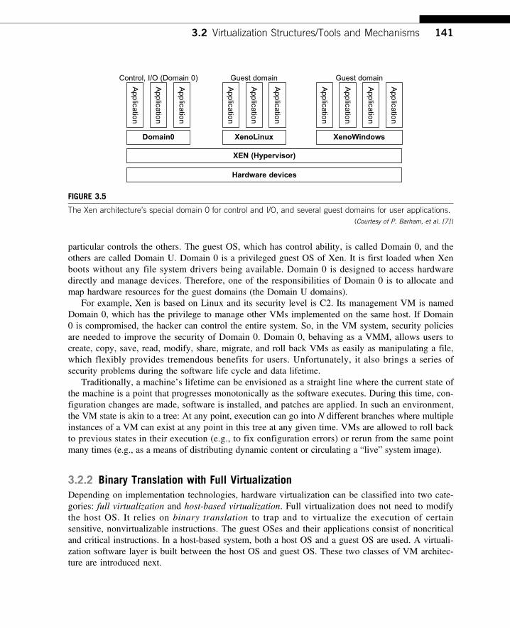
particular controls the others. The guest OS, which has control ability, is called Domain 0, and theothers are called Domain U. Domain 0 is a privileged guest OS of Xen. It is first loaded when Xenboots without any file system drivers being available. Domain 0 is designed to access hardwaredirectly and manage devices. Therefore, one of the responsibilities of Domain 0 is to allocate andmap hardware resources for the guest domains (the Domain U domains).
For example, Xen is based on Linux and its security level is C2. Its management VM is namedDomain 0, which has the privilege to manage other VMs implemented on the same host. If Domain0 is compromised, the hacker can control the entire system. So, in the VM system, security policiesare needed to improve the security of Domain 0. Domain 0, behaving as a VMM, allows users tocreate, copy, save, read, modify, share, migrate, and roll back VMs as easily as manipulating a file,which flexibly provides tremendous benefits for users. Unfortunately, it also brings a series ofsecurity problems during the software life cycle and data lifetime.
Traditionally, a machine’s lifetime can be envisioned as a straight line where the current state ofthe machine is a point that progresses monotonically as the software executes. During this time, con-figuration changes are made, software is installed, and patches are applied. In such an environment,the VM state is akin to a tree: At any point, execution can go into N different branches where multipleinstances of a VM can exist at any point in this tree at any given time. VMs are allowed to roll backto previous states in their execution (e.g., to fix configuration errors) or rerun from the same pointmany times (e.g., as a means of distributing dynamic content or circulating a “live” system image).
3.2.2 Binary Translation with Full VirtualizationDepending on implementation technologies, hardware virtualization can be classified into two cate-gories: full virtualization and host-based virtualization. Full virtualization does not need to modifythe host OS. It relies on binary translation to trap and to virtualize the execution of certainsensitive, nonvirtualizable instructions. The guest OSes and their applications consist of noncriticaland critical instructions. In a host-based system, both a host OS and a guest OS are used. A virtuali-zation software layer is built between the host OS and guest OS. These two classes of VM architec-ture are introduced next.
Domain0 XenoLinux
XEN (Hypervisor)
Hardware devices
XenoWindows
Control, I/O (Domain 0)
Application
Application
Application
Application
Application
Application
Application
Application
Application
Application
Guest domain Guest domain
FIGURE 3.5
The Xen architecture’s special domain 0 for control and I/O, and several guest domains for user applications.(Courtesy of P. Barham, et al. [7] )
3.2 Virtualization Structures/Tools and Mechanisms 141
3.2.2.1 Full VirtualizationWith full virtualization, noncritical instructions run on the hardware directly while criticalinstructions are discovered and replaced with traps into the VMM to be emulated by software. Boththe hypervisor and VMM approaches are considered full virtualization. Why are only criticalinstructions trapped into the VMM? This is because binary translation can incur a large performanceoverhead. Noncritical instructions do not control hardware or threaten the security of the system, butcritical instructions do. Therefore, running noncritical instructions on hardware not only canpromote efficiency, but also can ensure system security.
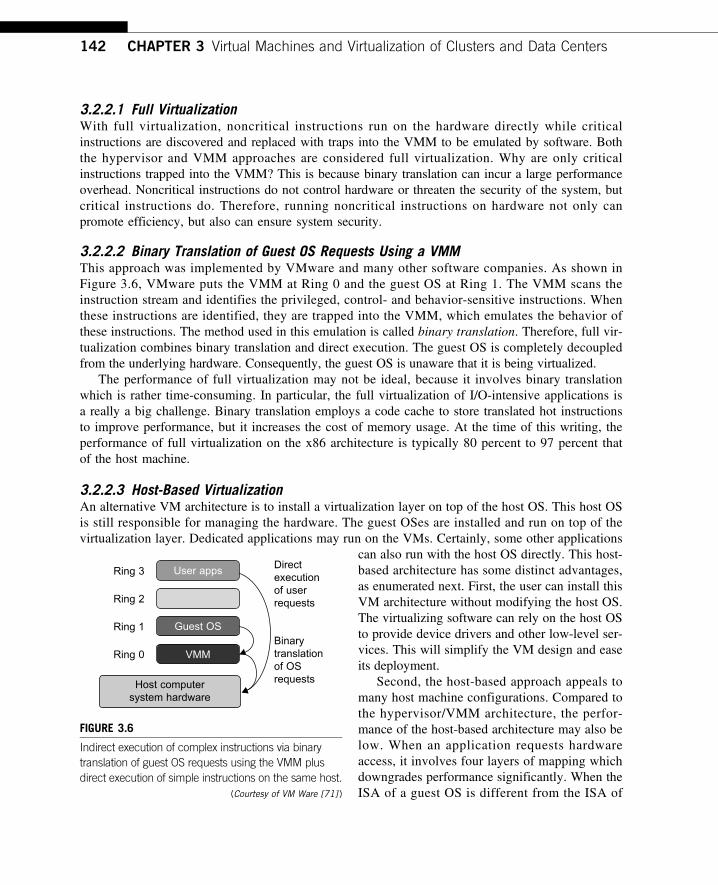
3.2.2.2 Binary Translation of Guest OS Requests Using a VMMThis approach was implemented by VMware and many other software companies. As shown inFigure 3.6, VMware puts the VMM at Ring 0 and the guest OS at Ring 1. The VMM scans theinstruction stream and identifies the privileged, control- and behavior-sensitive instructions. Whenthese instructions are identified, they are trapped into the VMM, which emulates the behavior ofthese instructions. The method used in this emulation is called binary translation. Therefore, full vir-tualization combines binary translation and direct execution. The guest OS is completely decoupledfrom the underlying hardware. Consequently, the guest OS is unaware that it is being virtualized.
The performance of full virtualization may not be ideal, because it involves binary translationwhich is rather time-consuming. In particular, the full virtualization of I/O-intensive applications isa really a big challenge. Binary translation employs a code cache to store translated hot instructionsto improve performance, but it increases the cost of memory usage. At the time of this writing, theperformance of full virtualization on the x86 architecture is typically 80 percent to 97 percent thatof the host machine.
3.2.2.3 Host-Based VirtualizationAn alternative VM architecture is to install a virtualization layer on top of the host OS. This host OSis still responsible for managing the hardware. The guest OSes are installed and run on top of thevirtualization layer. Dedicated applications may run on the VMs. Certainly, some other applications
can also run with the host OS directly. This host-based architecture has some distinct advantages,as enumerated next. First, the user can install thisVM architecture without modifying the host OS.The virtualizing software can rely on the host OSto provide device drivers and other low-level ser-vices. This will simplify the VM design and easeits deployment.
Second, the host-based approach appeals tomany host machine configurations. Compared tothe hypervisor/VMM architecture, the perfor-mance of the host-based architecture may also below. When an application requests hardwareaccess, it involves four layers of mapping whichdowngrades performance significantly. When theISA of a guest OS is different from the ISA of
Ring 3
Ring 2
Ring 1Binarytranslationof OSrequests
Directexecutionof userrequests
Ring 0
User apps
Guest OS
VMM
Host computersystem hardware
FIGURE 3.6
Indirect execution of complex instructions via binarytranslation of guest OS requests using the VMM plusdirect execution of simple instructions on the same host.
(Courtesy of VM Ware [71] )
142 CHAPTER 3 Virtual Machines and Virtualization of Clusters and Data Centers
the underlying hardware, binary translation must be adopted. Although the host-based architecture hasflexibility, the performance is too low to be useful in practice.
3.2.3 Para-Virtualization with Compiler SupportPara-virtualization needs to modify the guest operating systems. A para-virtualized VM providesspecial APIs requiring substantial OS modifications in user applications. Performance degradation isa critical issue of a virtualized system. No one wants to use a VM if it is much slower than using aphysical machine. The virtualization layer can be inserted at different positions in a machine soft-ware stack. However, para-virtualization attempts to reduce the virtualization overhead, and thusimprove performance by modifying only the guest OS kernel.
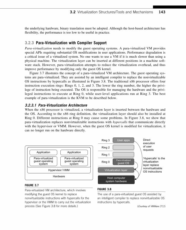
Figure 3.7 illustrates the concept of a para-virtualized VM architecture. The guest operating sys-tems are para-virtualized. They are assisted by an intelligent compiler to replace the nonvirtualizableOS instructions by hypercalls as illustrated in Figure 3.8. The traditional x86 processor offers fourinstruction execution rings: Rings 0, 1, 2, and 3. The lower the ring number, the higher the privi-lege of instruction being executed. The OS is responsible for managing the hardware and the privi-leged instructions to execute at Ring 0, while user-level applications run at Ring 3. The bestexample of para-virtualization is the KVM to be described below.
3.2.3.1 Para-Virtualization ArchitectureWhen the x86 processor is virtualized, a virtualization layer is inserted between the hardware andthe OS. According to the x86 ring definition, the virtualization layer should also be installed atRing 0. Different instructions at Ring 0 may cause some problems. In Figure 3.8, we show thatpara-virtualization replaces nonvirtualizable instructions with hypercalls that communicate directlywith the hypervisor or VMM. However, when the guest OS kernel is modified for virtualization, itcan no longer run on the hardware directly.
ApplicationApplication
Para-virtualizedguest operating
system
Hypervisor /VMM
Hardware
Para-virtualizedguest operating
system
FIGURE 3.7
Para-virtualized VM architecture, which involvesmodifying the guest OS kernel to replacenonvirtualizable instructions with hypercalls for thehypervisor or the VMM to carry out the virtualizationprocess (See Figure 3.8 for more details.)
Ring 3
Ring 2
Ring 1‘Hypercalls’ to thevirtualizationlayer replacenonvirtualizableOS instructions
Directexecutionof userrequests
Ring 0
User apps
Host computersystem hardware
Virtualization layer
Para-virtualized
guest OS
FIGURE 3.8
The use of a para-virtualized guest OS assisted byan intelligent compiler to replace nonvirtualizable OSinstructions by hypercalls.
(Courtesy of VMWare [71] )
3.2 Virtualization Structures/Tools and Mechanisms 143
Although para-virtualization reduces the overhead, it has incurred other problems. First, itscompatibility and portability may be in doubt, because it must support the unmodified OS aswell. Second, the cost of maintaining para-virtualized OSes is high, because they may requiredeep OS kernel modifications. Finally, the performance advantage of para-virtualization variesgreatly due to workload variations. Compared with full virtualization, para-virtualization isrelatively easy and more practical. The main problem in full virtualization is its low performancein binary translation. To speed up binary translation is difficult. Therefore, many virtualizationproducts employ the para-virtualization architecture. The popular Xen, KVM, and VMware ESXare good examples.
3.2.3.2 KVM (Kernel-Based VM)This is a Linux para-virtualization system—a part of the Linux version 2.6.20 kernel. Memorymanagement and scheduling activities are carried out by the existing Linux kernel. The KVM doesthe rest, which makes it simpler than the hypervisor that controls the entire machine. KVM is ahardware-assisted para-virtualization tool, which improves performance and supports unmodifiedguest OSes such as Windows, Linux, Solaris, and other UNIX variants.
3.2.3.3 Para-Virtualization with Compiler SupportUnlike the full virtualization architecture which intercepts and emulates privileged and sensitiveinstructions at runtime, para-virtualization handles these instructions at compile time. The guest OSkernel is modified to replace the privileged and sensitive instructions with hypercalls to the hypervi-sor or VMM. Xen assumes such a para-virtualization architecture.
The guest OS running in a guest domain may run at Ring 1 instead of at Ring 0. This impliesthat the guest OS may not be able to execute some privileged and sensitive instructions. Theprivileged instructions are implemented by hypercalls to the hypervisor. After replacing the instructionswith hypercalls, the modified guest OS emulates the behavior of the original guest OS. On an UNIXsystem, a system call involves an interrupt or service routine. The hypercalls apply a dedicated serviceroutine in Xen.
Example 3.3 VMware ESX Server for Para-Virtualization
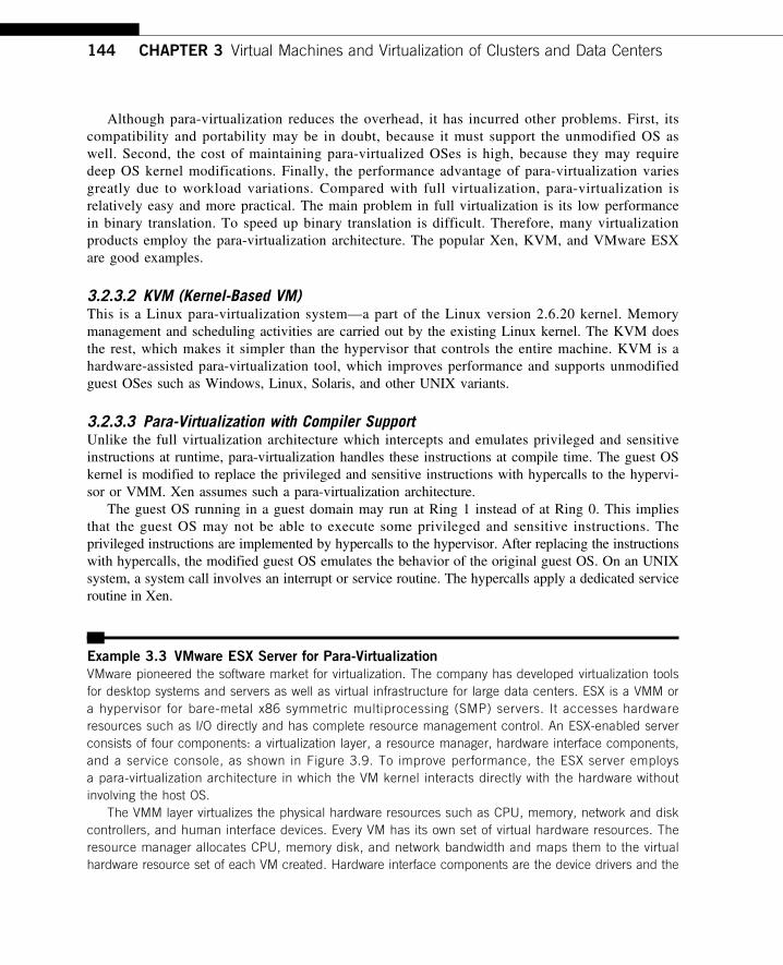
VMware pioneered the software market for virtualization. The company has developed virtualization toolsfor desktop systems and servers as well as virtual infrastructure for large data centers. ESX is a VMM ora hypervisor for bare-metal x86 symmetric multiprocessing (SMP) servers. It accesses hardwareresources such as I/O directly and has complete resource management control. An ESX-enabled serverconsists of four components: a virtualization layer, a resource manager, hardware interface components,and a service console, as shown in Figure 3.9. To improve performance, the ESX server employsa para-virtualization architecture in which the VM kernel interacts directly with the hardware withoutinvolving the host OS.
The VMM layer virtualizes the physical hardware resources such as CPU, memory, network and diskcontrollers, and human interface devices. Every VM has its own set of virtual hardware resources. Theresource manager allocates CPU, memory disk, and network bandwidth and maps them to the virtualhardware resource set of each VM created. Hardware interface components are the device drivers and the
144 CHAPTER 3 Virtual Machines and Virtualization of Clusters and Data Centers
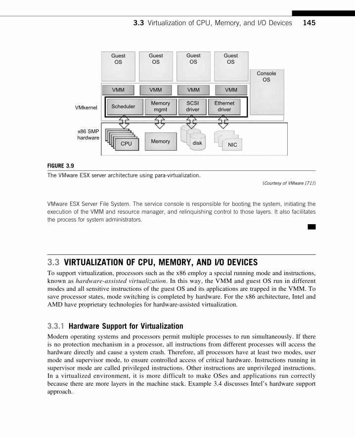
VMware ESX Server File System. The service console is responsible for booting the system, initiating theexecution of the VMM and resource manager, and relinquishing control to those layers. It also facilitatesthe process for system administrators.
3.3 VIRTUALIZATION OF CPU, MEMORY, AND I/O DEVICESTo support virtualization, processors such as the x86 employ a special running mode and instructions,known as hardware-assisted virtualization. In this way, the VMM and guest OS run in differentmodes and all sensitive instructions of the guest OS and its applications are trapped in the VMM. Tosave processor states, mode switching is completed by hardware. For the x86 architecture, Intel andAMD have proprietary technologies for hardware-assisted virtualization.
3.3.1 Hardware Support for VirtualizationModern operating systems and processors permit multiple processes to run simultaneously. If thereis no protection mechanism in a processor, all instructions from different processes will access thehardware directly and cause a system crash. Therefore, all processors have at least two modes, usermode and supervisor mode, to ensure controlled access of critical hardware. Instructions running insupervisor mode are called privileged instructions. Other instructions are unprivileged instructions.In a virtualized environment, it is more difficult to make OSes and applications run correctlybecause there are more layers in the machine stack. Example 3.4 discusses Intel’s hardware supportapproach.
GuestOS
VMM
VMkernel
x86 SMPhardware
Scheduler
CPU Memory disk NIC
Memorymgmt
SCSIdriver
Ethernetdriver
VMM VMM VMM
ConsoleOS
GuestOS
GuestOS
GuestOS
FIGURE 3.9
The VMware ESX server architecture using para-virtualization.(Courtesy of VMware [71] )
3.3 Virtualization of CPU, Memory, and I/O Devices 145
At the time of this writing, many hardware virtualization products were available. The VMwareWorkstation is a VM software suite for x86 and x86-64 computers. This software suite allows usersto set up multiple x86 and x86-64 virtual computers and to use one or more of these VMs simulta-neously with the host operating system. The VMware Workstation assumes the host-based virtuali-zation. Xen is a hypervisor for use in IA-32, x86-64, Itanium, and PowerPC 970 hosts. Actually,Xen modifies Linux as the lowest and most privileged layer, or a hypervisor.
One or more guest OS can run on top of the hypervisor. KVM (Kernel-based Virtual Machine)is a Linux kernel virtualization infrastructure. KVM can support hardware-assisted virtualization andparavirtualization by using the Intel VT-x or AMD-v and VirtIO framework, respectively. TheVirtIO framework includes a paravirtual Ethernet card, a disk I/O controller, a balloon device foradjusting guest memory usage, and a VGA graphics interface using VMware drivers.
Example 3.4 Hardware Support for Virtualization in the Intel x86 Processor
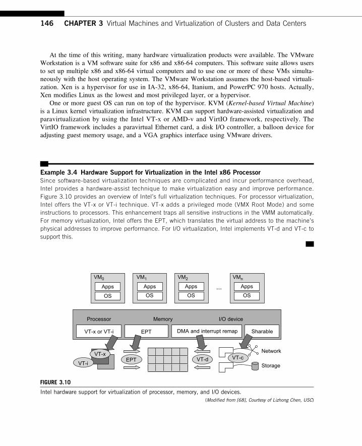
Since software-based virtualization techniques are complicated and incur performance overhead,Intel provides a hardware-assist technique to make virtualization easy and improve performance.Figure 3.10 provides an overview of Intel’s full virtualization techniques. For processor virtualization,Intel offers the VT-x or VT-i technique. VT-x adds a privileged mode (VMX Root Mode) and someinstructions to processors. This enhancement traps all sensitive instructions in the VMM automatically.For memory virtualization, Intel offers the EPT, which translates the virtual address to the machine’sphysical addresses to improve performance. For I/O virtualization, Intel implements VT-d and VT-c tosupport this.
VM0
Apps
OS OS OS
Apps Apps ...
Processor
VT-x or VT-i
VT-i
VT-xEPT VT-d VT-c
EPT DMA and interrupt remap Sharable
Network
Storage
Memory I/O device
OS
Apps
VM1 VM2 VMn
FIGURE 3.10
Intel hardware support for virtualization of processor, memory, and I/O devices.(Modified from [68], Courtesy of Lizhong Chen, USC)
146 CHAPTER 3 Virtual Machines and Virtualization of Clusters and Data Centers
3.3.2 CPU VirtualizationA VM is a duplicate of an existing computer system in which a majority of the VM instructions areexecuted on the host processor in native mode. Thus, unprivileged instructions of VMs run directly on thehost machine for higher efficiency. Other critical instructions should be handled carefully for correctnessand stability. The critical instructions are divided into three categories: privileged instructions, control-sensitive instructions, and behavior-sensitive instructions. Privileged instructions execute in a privilegedmode and will be trapped if executed outside this mode. Control-sensitive instructions attempt to changethe configuration of resources used. Behavior-sensitive instructions have different behaviors dependingon the configuration of resources, including the load and store operations over the virtual memory.
A CPU architecture is virtualizable if it supports the ability to run the VM’s privileged andunprivileged instructions in the CPU’s user mode while the VMM runs in supervisor mode. Whenthe privileged instructions including control- and behavior-sensitive instructions of a VM are exe-cuted, they are trapped in the VMM. In this case, the VMM acts as a unified mediator for hardwareaccess from different VMs to guarantee the correctness and stability of the whole system. However,not all CPU architectures are virtualizable. RISC CPU architectures can be naturally virtualizedbecause all control- and behavior-sensitive instructions are privileged instructions. On the contrary,x86 CPU architectures are not primarily designed to support virtualization. This is because about 10sensitive instructions, such as SGDT and SMSW, are not privileged instructions. When these instruc-tions execute in virtualization, they cannot be trapped in the VMM.
On a native UNIX-like system, a system call triggers the 80h interrupt and passes control to theOS kernel. The interrupt handler in the kernel is then invoked to process the system call. On a para-virtualization system such as Xen, a system call in the guest OS first triggers the 80h interrupt nor-mally. Almost at the same time, the 82h interrupt in the hypervisor is triggered. Incidentally,control is passed on to the hypervisor as well. When the hypervisor completes its task for the guestOS system call, it passes control back to the guest OS kernel. Certainly, the guest OS kernel mayalso invoke the hypercall while it’s running. Although paravirtualization of a CPU lets unmodifiedapplications run in the VM, it causes a small performance penalty.
3.3.2.1 Hardware-Assisted CPU VirtualizationThis technique attempts to simplify virtualization because full or paravirtualization is complicated.Intel and AMD add an additional mode called privilege mode level (some people call it Ring-1) tox86 processors. Therefore, operating systems can still run at Ring 0 and the hypervisor can run atRing -1. All the privileged and sensitive instructions are trapped in the hypervisor automatically.This technique removes the difficulty of implementing binary translation of full virtualization. Italso lets the operating system run in VMs without modification.
Example 3.5 Intel Hardware-Assisted CPU Virtualization
Although x86 processors are not virtualizable primarily, great effort is taken to virtualize them. They are usedwidely in comparing RISC processors that the bulk of x86-based legacy systems cannot discard easily. Virtuali-zation of x86 processors is detailed in the following sections. Intel’s VT-x technology is an example ofhardware-assisted virtualization, as shown in Figure 3.11. Intel calls the privilege level of x86 processors theVMX Root Mode. In order to control the start and stop of a VM and allocate a memory page to maintain the
3.3 Virtualization of CPU, Memory, and I/O Devices 147
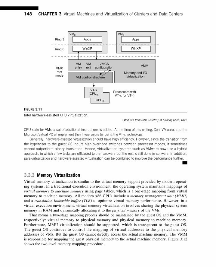
CPU state for VMs, a set of additional instructions is added. At the time of this writing, Xen, VMware, and theMicrosoft Virtual PC all implement their hypervisors by using the VT-x technology.
Generally, hardware-assisted virtualization should have high efficiency. However, since the transition fromthe hypervisor to the guest OS incurs high overhead switches between processor modes, it sometimescannot outperform binary translation. Hence, virtualization systems such as VMware now use a hybridapproach, in which a few tasks are offloaded to the hardware but the rest is still done in software. In addition,para-virtualization and hardware-assisted virtualization can be combined to improve the performance further.
3.3.3 Memory VirtualizationVirtual memory virtualization is similar to the virtual memory support provided by modern operat-ing systems. In a traditional execution environment, the operating system maintains mappings ofvirtual memory to machine memory using page tables, which is a one-stage mapping from virtualmemory to machine memory. All modern x86 CPUs include a memory management unit (MMU)and a translation lookaside buffer (TLB) to optimize virtual memory performance. However, in avirtual execution environment, virtual memory virtualization involves sharing the physical systemmemory in RAM and dynamically allocating it to the physical memory of the VMs.
That means a two-stage mapping process should be maintained by the guest OS and the VMM,respectively: virtual memory to physical memory and physical memory to machine memory.Furthermore, MMU virtualization should be supported, which is transparent to the guest OS.The guest OS continues to control the mapping of virtual addresses to the physical memoryaddresses of VMs. But the guest OS cannot directly access the actual machine memory. The VMMis responsible for mapping the guest physical memory to the actual machine memory. Figure 3.12shows the two-level memory mapping procedure.
VT-xCPU0
VM0
Ring 3
Ring 0
VMXroot
mode
Apps
WinXP
VM0
Apps
WinXP
VMMVM
entry
VM control structure
VMexit
VMCSconfiguration
Memory and I/Ovirtualization
VT-xCPU0
Processors withVT-x (or VT-i)
FIGURE 3.11
Intel hardware-assisted CPU virtualization.(Modified from [68], Courtesy of Lizhong Chen, USC)
148 CHAPTER 3 Virtual Machines and Virtualization of Clusters and Data Centers
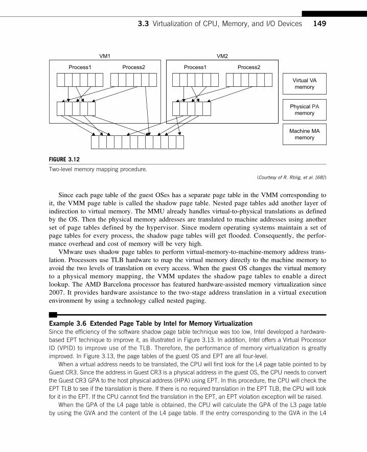
Since each page table of the guest OSes has a separate page table in the VMM corresponding toit, the VMM page table is called the shadow page table. Nested page tables add another layer ofindirection to virtual memory. The MMU already handles virtual-to-physical translations as definedby the OS. Then the physical memory addresses are translated to machine addresses using anotherset of page tables defined by the hypervisor. Since modern operating systems maintain a set ofpage tables for every process, the shadow page tables will get flooded. Consequently, the perfor-mance overhead and cost of memory will be very high.
VMware uses shadow page tables to perform virtual-memory-to-machine-memory address trans-lation. Processors use TLB hardware to map the virtual memory directly to the machine memory toavoid the two levels of translation on every access. When the guest OS changes the virtual memoryto a physical memory mapping, the VMM updates the shadow page tables to enable a directlookup. The AMD Barcelona processor has featured hardware-assisted memory virtualization since2007. It provides hardware assistance to the two-stage address translation in a virtual executionenvironment by using a technology called nested paging.
Example 3.6 Extended Page Table by Intel for Memory Virtualization
Since the efficiency of the software shadow page table technique was too low, Intel developed a hardware-based EPT technique to improve it, as illustrated in Figure 3.13. In addition, Intel offers a Virtual ProcessorID (VPID) to improve use of the TLB. Therefore, the performance of memory virtualization is greatlyimproved. In Figure 3.13, the page tables of the guest OS and EPT are all four-level.
When a virtual address needs to be translated, the CPU will first look for the L4 page table pointed to byGuest CR3. Since the address in Guest CR3 is a physical address in the guest OS, the CPU needs to convertthe Guest CR3 GPA to the host physical address (HPA) using EPT. In this procedure, the CPU will check theEPT TLB to see if the translation is there. If there is no required translation in the EPT TLB, the CPU will lookfor it in the EPT. If the CPU cannot find the translation in the EPT, an EPT violation exception will be raised.
When the GPA of the L4 page table is obtained, the CPU will calculate the GPA of the L3 page tableby using the GVA and the content of the L4 page table. If the entry corresponding to the GVA in the L4
VM1
Process1 Process2
VM2
Process1 Process2
Virtual VAmemory
Physical PAmemory
Machine MAmemory
FIGURE 3.12
Two-level memory mapping procedure.(Courtesy of R. Rblig, et al. [68] )
3.3 Virtualization of CPU, Memory, and I/O Devices 149
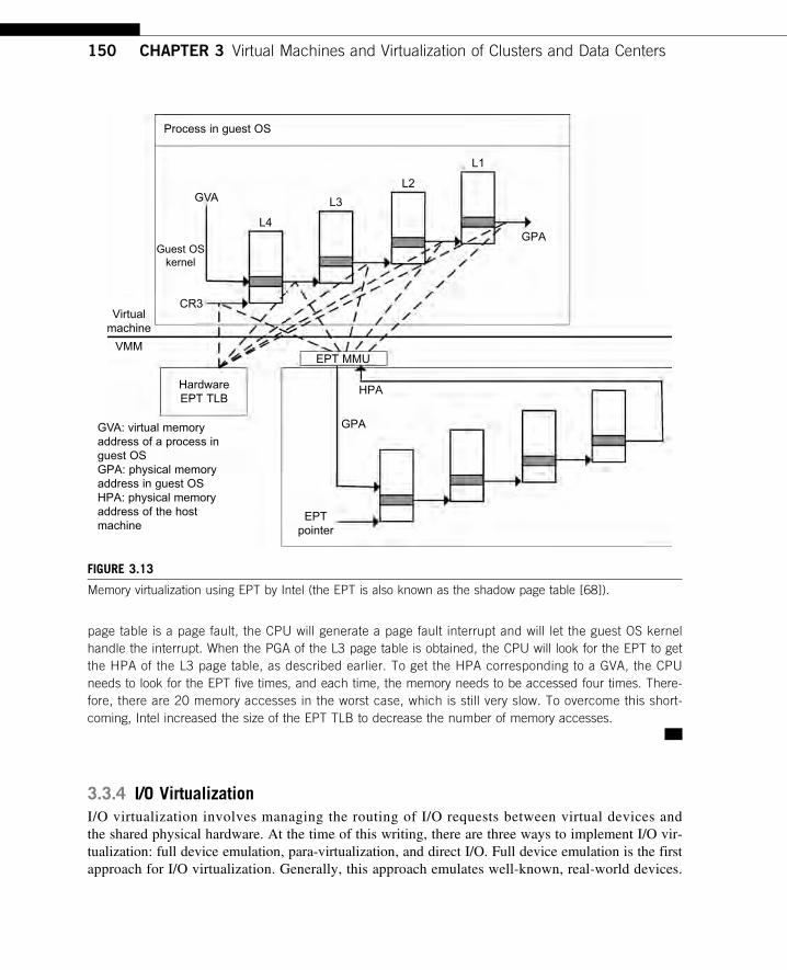
page table is a page fault, the CPU will generate a page fault interrupt and will let the guest OS kernelhandle the interrupt. When the PGA of the L3 page table is obtained, the CPU will look for the EPT to getthe HPA of the L3 page table, as described earlier. To get the HPA corresponding to a GVA, the CPUneeds to look for the EPT five times, and each time, the memory needs to be accessed four times. There-fore, there are 20 memory accesses in the worst case, which is still very slow. To overcome this short-coming, Intel increased the size of the EPT TLB to decrease the number of memory accesses.
3.3.4 I/O VirtualizationI/O virtualization involves managing the routing of I/O requests between virtual devices andthe shared physical hardware. At the time of this writing, there are three ways to implement I/O vir-tualization: full device emulation, para-virtualization, and direct I/O. Full device emulation is the firstapproach for I/O virtualization. Generally, this approach emulates well-known, real-world devices.
Process in guest OS
GVA
CR3
GPA
EPT MMU
HPA
GPA
EPTpointer
HardwareEPT TLB
GVA: virtual memoryaddress of a process inguest OSGPA: physical memoryaddress in guest OSHPA: physical memoryaddress of the hostmachine
L4
L3
L1
L2
Guest OSkernel
Virtualmachine
VMM
FIGURE 3.13
Memory virtualization using EPT by Intel (the EPT is also known as the shadow page table [68]).
150 CHAPTER 3 Virtual Machines and Virtualization of Clusters and Data Centers
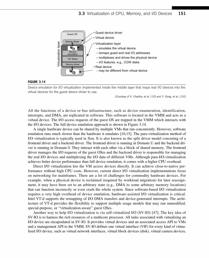
All the functions of a device or bus infrastructure, such as device enumeration, identification,interrupts, and DMA, are replicated in software. This software is located in the VMM and acts as avirtual device. The I/O access requests of the guest OS are trapped in the VMM which interacts withthe I/O devices. The full device emulation approach is shown in Figure 3.14.
A single hardware device can be shared by multiple VMs that run concurrently. However, softwareemulation runs much slower than the hardware it emulates [10,15]. The para-virtualization method ofI/O virtualization is typically used in Xen. It is also known as the split driver model consisting of afrontend driver and a backend driver. The frontend driver is running in Domain U and the backend dri-ver is running in Domain 0. They interact with each other via a block of shared memory. The frontenddriver manages the I/O requests of the guest OSes and the backend driver is responsible for managingthe real I/O devices and multiplexing the I/O data of different VMs. Although para-I/O-virtualizationachieves better device performance than full device emulation, it comes with a higher CPU overhead.
Direct I/O virtualization lets the VM access devices directly. It can achieve close-to-native per-formance without high CPU costs. However, current direct I/O virtualization implementations focuson networking for mainframes. There are a lot of challenges for commodity hardware devices. Forexample, when a physical device is reclaimed (required by workload migration) for later reassign-ment, it may have been set to an arbitrary state (e.g., DMA to some arbitrary memory locations)that can function incorrectly or even crash the whole system. Since software-based I/O virtualizationrequires a very high overhead of device emulation, hardware-assisted I/O virtualization is critical.Intel VT-d supports the remapping of I/O DMA transfers and device-generated interrupts. The archi-tecture of VT-d provides the flexibility to support multiple usage models that may run unmodified,special-purpose, or “virtualization-aware” guest OSes.
Another way to help I/O virtualization is via self-virtualized I/O (SV-IO) [47]. The key idea ofSV-IO is to harness the rich resources of a multicore processor. All tasks associated with virtualizing anI/O device are encapsulated in SV-IO. It provides virtual devices and an associated access API to VMsand a management API to the VMM. SV-IO defines one virtual interface (VIF) for every kind of virtua-lized I/O device, such as virtual network interfaces, virtual block devices (disk), virtual camera devices,
• Guest device driverGuest OS
Device driver
Deviceemulation
I/O Stack
Device driver
• Virtual device
• Real device – may be different from virtual device
Virt
ualiz
atio
n la
yer
• Virtualization layer
– emulates the virtual device
– remaps guest and real I/O addresses
– multiplexes and drives the physical device
– I/O features. e.g., COW disks
FIGURE 3.14
Device emulation for I/O virtualization implemented inside the middle layer that maps real I/O devices into thevirtual devices for the guest device driver to use.
(Courtesy of V. Chadha, et al. [10] and Y. Dong, et al. [15] )
3.3 Virtualization of CPU, Memory, and I/O Devices 151
and others. The guest OS interacts with the VIFs via VIF device drivers. Each VIF consists of two mes-sage queues. One is for outgoing messages to the devices and the other is for incoming messages fromthe devices. In addition, each VIF has a unique ID for identifying it in SV-IO.
Example 3.7 VMware Workstation for I/O Virtualization
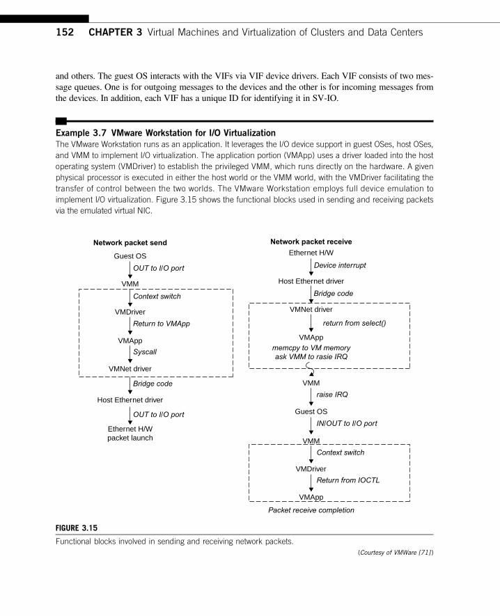
The VMware Workstation runs as an application. It leverages the I/O device support in guest OSes, host OSes,and VMM to implement I/O virtualization. The application portion (VMApp) uses a driver loaded into the hostoperating system (VMDriver) to establish the privileged VMM, which runs directly on the hardware. A givenphysical processor is executed in either the host world or the VMM world, with the VMDriver facilitating thetransfer of control between the two worlds. The VMware Workstation employs full device emulation toimplement I/O virtualization. Figure 3.15 shows the functional blocks used in sending and receiving packetsvia the emulated virtual NIC.
Network packet send Network packet receive
Host Ethernet driver
VMApp
VMNet driver
memcpy to VM memoryask VMM to rasie IRQ
return from select()
raise IRQ
VMM
Guest OS
VMM
IN/OUT to I/O port
Context switch
Return from IOCTL
VMApp
Packet receive completion
VMDriver
Bridge code
Device interrupt
Ethernet H/WGuest OS
OUT to I/O port
Context switch
Return to VMApp
Syscall
Bridge code
OUT to I/O port
VMM
VMDriver
VMApp
VMNet driver
Host Ethernet driver
Ethernet H/Wpacket launch
FIGURE 3.15
Functional blocks involved in sending and receiving network packets.(Courtesy of VMWare [71] )
152 CHAPTER 3 Virtual Machines and Virtualization of Clusters and Data Centers
The virtual NIC models an AMD Lance Am79C970A controller. The device driver for a Lance controllerin the guest OS initiates packet transmissions by reading and writing a sequence of virtual I/O ports; eachread or write switches back to the VMApp to emulate the Lance port accesses. When the last OUT instruc-tion of the sequence is encountered, the Lance emulator calls a normal write() to the VMNet driver. TheVMNet driver then passes the packet onto the network via a host NIC and then the VMApp switches backto the VMM. The switch raises a virtual interrupt to notify the guest device driver that the packet was sent.Packet receives occur in reverse.
3.3.5 Virtualization in Multi-Core ProcessorsVirtualizing a multi-core processor is relatively more complicated than virtualizing a uni-core processor.Though multicore processors are claimed to have higher performance by integrating multiple processorcores in a single chip, muti-core virtualiuzation has raised some new challenges to computer architects,compiler constructors, system designers, and application programmers. There are mainly two difficul-ties: Application programs must be parallelized to use all cores fully, and software must explicitlyassign tasks to the cores, which is a very complex problem.
Concerning the first challenge, new programming models, languages, and libraries are needed tomake parallel programming easier. The second challenge has spawned research involving schedulingalgorithms and resource management policies. Yet these efforts cannot balance well among perfor-mance, complexity, and other issues. What is worse, as technology scales, a new challenge calleddynamic heterogeneity is emerging to mix the fat CPU core and thin GPU cores on the same chip,which further complicates the multi-core or many-core resource management. The dynamic hetero-geneity of hardware infrastructure mainly comes from less reliable transistors and increased complexityin using the transistors [33,66].
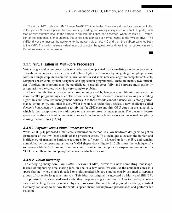
3.3.5.1 Physical versus Virtual Processor CoresWells, et al. [74] proposed a multicore virtualization method to allow hardware designers to get anabstraction of the low-level details of the processor cores. This technique alleviates the burden andinefficiency of managing hardware resources by software. It is located under the ISA and remainsunmodified by the operating system or VMM (hypervisor). Figure 3.16 illustrates the technique of asoftware-visible VCPU moving from one core to another and temporarily suspending execution of aVCPU when there are no appropriate cores on which it can run.
3.3.5.2 Virtual HierarchyThe emerging many-core chip multiprocessors (CMPs) provides a new computing landscape.Instead of supporting time-sharing jobs on one or a few cores, we can use the abundant cores in aspace-sharing, where single-threaded or multithreaded jobs are simultaneously assigned to separategroups of cores for long time intervals. This idea was originally suggested by Marty and Hill [39].To optimize for space-shared workloads, they propose using virtual hierarchies to overlay a coher-ence and caching hierarchy onto a physical processor. Unlike a fixed physical hierarchy, a virtualhierarchy can adapt to fit how the work is space shared for improved performance and performanceisolation.
3.3 Virtualization of CPU, Memory, and I/O Devices 153
Today’s many-core CMPs use a physical hierarchy of two or more cache levels that stati-cally determine the cache allocation and mapping. A virtual hierarchy is a cache hierarchythat can adapt to fit the workload or mix of workloads [39]. The hierarchy’s first level locatesdata blocks close to the cores needing them for faster access, establishes a shared-cache domain,and establishes a point of coherence for faster communication. When a miss leaves a tile, itfirst attempts to locate the block (or sharers) within the first level. The first level can also pro-vide isolation between independent workloads. A miss at the L1 cache can invoke the L2access.
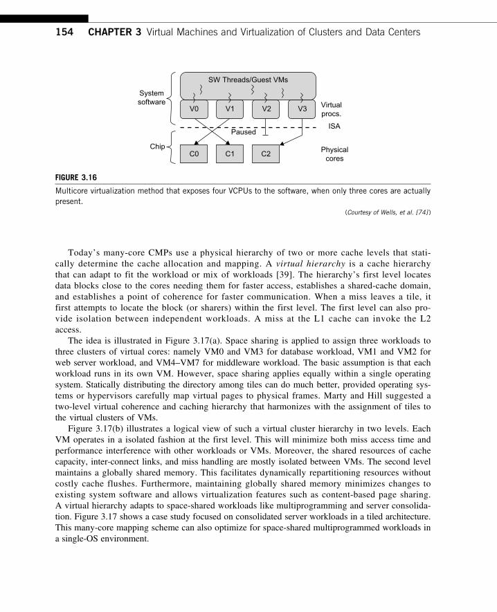
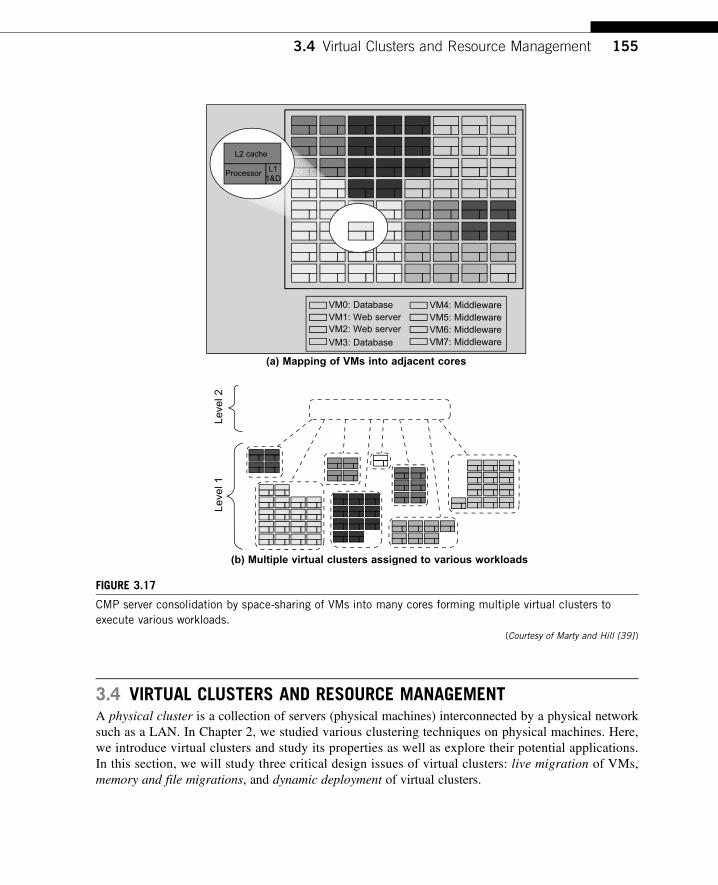
The idea is illustrated in Figure 3.17(a). Space sharing is applied to assign three workloads tothree clusters of virtual cores: namely VM0 and VM3 for database workload, VM1 and VM2 forweb server workload, and VM4–VM7 for middleware workload. The basic assumption is that eachworkload runs in its own VM. However, space sharing applies equally within a single operatingsystem. Statically distributing the directory among tiles can do much better, provided operating sys-tems or hypervisors carefully map virtual pages to physical frames. Marty and Hill suggested atwo-level virtual coherence and caching hierarchy that harmonizes with the assignment of tiles tothe virtual clusters of VMs.
Figure 3.17(b) illustrates a logical view of such a virtual cluster hierarchy in two levels. EachVM operates in a isolated fashion at the first level. This will minimize both miss access time andperformance interference with other workloads or VMs. Moreover, the shared resources of cachecapacity, inter-connect links, and miss handling are mostly isolated between VMs. The second levelmaintains a globally shared memory. This facilitates dynamically repartitioning resources withoutcostly cache flushes. Furthermore, maintaining globally shared memory minimizes changes toexisting system software and allows virtualization features such as content-based page sharing.A virtual hierarchy adapts to space-shared workloads like multiprogramming and server consolida-tion. Figure 3.17 shows a case study focused on consolidated server workloads in a tiled architecture.This many-core mapping scheme can also optimize for space-shared multiprogrammed workloads ina single-OS environment.
C0
V0
Systemsoftware
Chip
SW Threads/Guest VMs
Virtualprocs.
ISA
Physicalcores
Paused
V1 V2 V3
C1 C2
FIGURE 3.16
Multicore virtualization method that exposes four VCPUs to the software, when only three cores are actuallypresent.
(Courtesy of Wells, et al. [74] )
154 CHAPTER 3 Virtual Machines and Virtualization of Clusters and Data Centers
3.4 VIRTUAL CLUSTERS AND RESOURCE MANAGEMENTA physical cluster is a collection of servers (physical machines) interconnected by a physical networksuch as a LAN. In Chapter 2, we studied various clustering techniques on physical machines. Here,we introduce virtual clusters and study its properties as well as explore their potential applications.In this section, we will study three critical design issues of virtual clusters: live migration of VMs,memory and file migrations, and dynamic deployment of virtual clusters.
VM1: Web serverVM2: Web server
VM0: Database VM4: MiddlewareVM5: MiddlewareVM6: MiddlewareVM7: MiddlewareVM3: Database
(a) Mapping of VMs into adjacent cores
L2 cache
Processor L11&D
(b) Multiple virtual clusters assigned to various workloads
Leve
l 1Le
vel 2
FIGURE 3.17
CMP server consolidation by space-sharing of VMs into many cores forming multiple virtual clusters toexecute various workloads.
(Courtesy of Marty and Hill [39] )
3.4 Virtual Clusters and Resource Management 155
When a traditional VM is initialized, the administrator needs to manually write configurationinformation or specify the configuration sources. When more VMs join a network, an inefficientconfiguration always causes problems with overloading or underutilization. Amazon’s ElasticCompute Cloud (EC2) is a good example of a web service that provides elastic computing power ina cloud. EC2 permits customers to create VMs and to manage user accounts over the time of theiruse. Most virtualization platforms, including XenServer and VMware ESX Server, support a brid-ging mode which allows all domains to appear on the network as individual hosts. By using thismode, VMs can communicate with one another freely through the virtual network interface cardand configure the network automatically.
3.4.1 Physical versus Virtual ClustersVirtual clusters are built with VMs installed at distributed servers from one or more physical clus-ters. The VMs in a virtual cluster are interconnected logically by a virtual network across severalphysical networks. Figure 3.18 illustrates the concepts of virtual clusters and physical clusters. Eachvirtual cluster is formed with physical machines or a VM hosted by multiple physical clusters. Thevirtual cluster boundaries are shown as distinct boundaries.
The provisioning of VMs to a virtual cluster is done dynamically to have the following interest-ing properties:
• The virtual cluster nodes can be either physical or virtual machines. Multiple VMs running withdifferent OSes can be deployed on the same physical node.
• A VM runs with a guest OS, which is often different from the host OS, that manages theresources in the physical machine, where the VM is implemented.
• The purpose of using VMs is to consolidate multiple functionalities on the same server. Thiswill greatly enhance server utilization and application flexibility.
Physicalcluster 1
Physicalcluster 2
Physicalcluster 3
Virtualmachines
VirtualCluster 1
Virtualcluster 4
Virtualcluster 3
Virtualcluster 2
Virtualcluster 1
FIGURE 3.18
A cloud platform with four virtual clusters over three physical clusters shaded differently.(Courtesy of Fan Zhang, Tsinghua University )
156 CHAPTER 3 Virtual Machines and Virtualization of Clusters and Data Centers
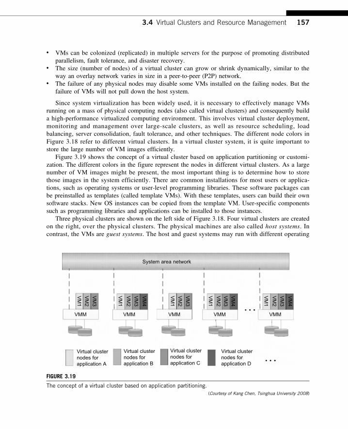
• VMs can be colonized (replicated) in multiple servers for the purpose of promoting distributedparallelism, fault tolerance, and disaster recovery.
• The size (number of nodes) of a virtual cluster can grow or shrink dynamically, similar to theway an overlay network varies in size in a peer-to-peer (P2P) network.
• The failure of any physical nodes may disable some VMs installed on the failing nodes. But thefailure of VMs will not pull down the host system.
Since system virtualization has been widely used, it is necessary to effectively manage VMsrunning on a mass of physical computing nodes (also called virtual clusters) and consequently builda high-performance virtualized computing environment. This involves virtual cluster deployment,monitoring and management over large-scale clusters, as well as resource scheduling, loadbalancing, server consolidation, fault tolerance, and other techniques. The different node colors inFigure 3.18 refer to different virtual clusters. In a virtual cluster system, it is quite important tostore the large number of VM images efficiently.
Figure 3.19 shows the concept of a virtual cluster based on application partitioning or customi-zation. The different colors in the figure represent the nodes in different virtual clusters. As a largenumber of VM images might be present, the most important thing is to determine how to storethose images in the system efficiently. There are common installations for most users or applica-tions, such as operating systems or user-level programming libraries. These software packages canbe preinstalled as templates (called template VMs). With these templates, users can build their ownsoftware stacks. New OS instances can be copied from the template VM. User-specific componentssuch as programming libraries and applications can be installed to those instances.
Three physical clusters are shown on the left side of Figure 3.18. Four virtual clusters are createdon the right, over the physical clusters. The physical machines are also called host systems. Incontrast, the VMs are guest systems. The host and guest systems may run with different operating
System area network
Virtual clusternodes forapplication A
Virtual clusternodes forapplication B
Virtual clusternodes forapplication C
Virtual clusternodes forapplication D
VMMVMMVMMVMMVMM
VM
1
VM
2
VM
3
VM
1
VM
2
VM
3
VM
1
VM
2
VM
3
VM
4
VM
1
VM
2
VM
3
VM
4
VM
1
VM
2V
M3
VM
4
FIGURE 3.19
The concept of a virtual cluster based on application partitioning.(Courtesy of Kang Chen, Tsinghua University 2008)
3.4 Virtual Clusters and Resource Management 157
systems. Each VM can be installed on a remote server or replicated on multiple servers belonging tothe same or different physical clusters. The boundary of a virtual cluster can change as VM nodes areadded, removed, or migrated dynamically over time.
3.4.1.1 Fast Deployment and Effective SchedulingThe system should have the capability of fast deployment. Here, deployment means two things:to construct and distribute software stacks (OS, libraries, applications) to a physical node inside clus-ters as fast as possible, and to quickly switch runtime environments from one user’s virtual cluster toanother user’s virtual cluster. If one user finishes using his system, the corresponding virtual clustershould shut down or suspend quickly to save the resources to run other VMs for other users.
The concept of “green computing” has attracted much attention recently. However, previousapproaches have focused on saving the energy cost of components in a single workstation without aglobal vision. Consequently, they do not necessarily reduce the power consumption of the whole clus-ter. Other cluster-wide energy-efficient techniques can only be applied to homogeneous workstationsand specific applications. The live migration of VMs allows workloads of one node to transfer toanother node. However, it does not guarantee that VMs can randomly migrate among themselves. Infact, the potential overhead caused by live migrations of VMs cannot be ignored.
The overhead may have serious negative effects on cluster utilization, throughput, and QoSissues. Therefore, the challenge is to determine how to design migration strategies to implementgreen computing without influencing the performance of clusters. Another advantage of virtualiza-tion is load balancing of applications in a virtual cluster. Load balancing can be achieved using theload index and frequency of user logins. The automatic scale-up and scale-down mechanism of avirtual cluster can be implemented based on this model. Consequently, we can increase the resourceutilization of nodes and shorten the response time of systems. Mapping VMs onto the most appro-priate physical node should promote performance. Dynamically adjusting loads among nodes bylive migration of VMs is desired, when the loads on cluster nodes become quite unbalanced.
3.4.1.2 High-Performance Virtual StorageThe template VM can be distributed to several physical hosts in the cluster to customize the VMs. Inaddition, existing software packages reduce the time for customization as well as switching virtualenvironments. It is important to efficiently manage the disk spaces occupied by template softwarepackages. Some storage architecture design can be applied to reduce duplicated blocks in a distributedfile system of virtual clusters. Hash values are used to compare the contents of data blocks. Usershave their own profiles which store the identification of the data blocks for corresponding VMs in auser-specific virtual cluster. New blocks are created when users modify the corresponding data.Newly created blocks are identified in the users’ profiles.
Basically, there are four steps to deploy a group of VMs onto a target cluster: preparing the diskimage, configuring the VMs, choosing the destination nodes, and executing the VM deployment commandon every host. Many systems use templates to simplify the disk image preparation process. A template isa disk image that includes a preinstalled operating system with or without certain application software.Users choose a proper template according to their requirements and make a duplicate of it as their owndisk image. Templates could implement the COW (Copy on Write) format. A new COW backup file isvery small and easy to create and transfer. Therefore, it definitely reduces disk space consumption. Inaddition, VM deployment time is much shorter than that of copying the whole raw image file.
158 CHAPTER 3 Virtual Machines and Virtualization of Clusters and Data Centers
Every VM is configured with a name, disk image, network setting, and allocated CPU andmemory. One needs to record each VM configuration into a file. However, this method is inefficientwhen managing a large group of VMs. VMs with the same configurations could use preedited profilesto simplify the process. In this scenario, the system configures the VMs according to the chosen pro-file. Most configuration items use the same settings, while some of them, such as UUID, VM name,and IP address, are assigned with automatically calculated values. Normally, users do not care whichhost is running their VM. A strategy to choose the proper destination host for any VM is needed. Thedeployment principle is to fulfill the VM requirement and to balance workloads among the wholehost network.
3.4.2 Live VM Migration Steps and Performance EffectsIn a cluster built with mixed nodes of host and guest systems, the normal method of operation is torun everything on the physical machine. When a VM fails, its role could be replaced by another VMon a different node, as long as they both run with the same guest OS. In other words, a physical nodecan fail over to a VM on another host. This is different from physical-to-physical failover in a tradi-tional physical cluster. The advantage is enhanced failover flexibility. The potential drawback is thata VM must stop playing its role if its residing host node fails. However, this problem can be mitigatedwith VM life migration. Figure 3.20 shows the process of life migration of a VM from host A to hostB. The migration copies the VM state file from the storage area to the host machine.
There are four ways to manage a virtual cluster. First, you can use a guest-based manager, by whichthe cluster manager resides on a guest system. In this case, multiple VMs form a virtual cluster. Forexample, openMosix is an open source Linux cluster running different guest systems on top of the Xenhypervisor. Another example is Sun’s cluster Oasis, an experimental Solaris cluster of VMs supportedby a VMware VMM. Second, you can build a cluster manager on the host systems. The host-basedmanager supervises the guest systems and can restart the guest system on another physical machine.A good example is the VMware HA system that can restart a guest system after failure.
These two cluster management systems are either guest-only or host-only, but they do not mix. Athird way to manage a virtual cluster is to use an independent cluster manager on both the host andguest systems. This will make infrastructure management more complex, however. Finally, you canuse an integrated cluster on the guest and host systems. This means the manager must be designed todistinguish between virtualized resources and physical resources. Various cluster managementschemes can be greatly enhanced when VM life migration is enabled with minimal overhead.
VMs can be live-migrated from one physical machine to another; in case of failure, one VM can bereplaced by another VM. Virtual clusters can be applied in computational grids, cloud platforms, andhigh-performance computing (HPC) systems. The major attraction of this scenario is that virtual cluster-ing provides dynamic resources that can be quickly put together upon user demand or after a nodefailure. In particular, virtual clustering plays a key role in cloud computing. When a VM runs a live ser-vice, it is necessary to make a trade-off to ensure that the migration occurs in a manner that minimizesall three metrics. The motivation is to design a live VM migration scheme with negligible downtime,the lowest network bandwidth consumption possible, and a reasonable total migration time.
Furthermore, we should ensure that the migration will not disrupt other active services residingin the same host through resource contention (e.g., CPU, network bandwidth). A VM can be in oneof the following four states. An inactive state is defined by the virtualization platform, under which
3.4 Virtual Clusters and Resource Management 159
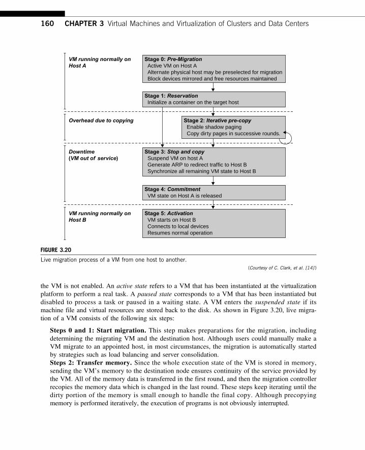
the VM is not enabled. An active state refers to a VM that has been instantiated at the virtualizationplatform to perform a real task. A paused state corresponds to a VM that has been instantiated butdisabled to process a task or paused in a waiting state. A VM enters the suspended state if itsmachine file and virtual resources are stored back to the disk. As shown in Figure 3.20, live migra-tion of a VM consists of the following six steps:
Steps 0 and 1: Start migration. This step makes preparations for the migration, includingdetermining the migrating VM and the destination host. Although users could manually make aVM migrate to an appointed host, in most circumstances, the migration is automatically startedby strategies such as load balancing and server consolidation.Steps 2: Transfer memory. Since the whole execution state of the VM is stored in memory,sending the VM’s memory to the destination node ensures continuity of the service provided bythe VM. All of the memory data is transferred in the first round, and then the migration controllerrecopies the memory data which is changed in the last round. These steps keep iterating until thedirty portion of the memory is small enough to handle the final copy. Although precopyingmemory is performed iteratively, the execution of programs is not obviously interrupted.
Stage 0: Pre-Migration Active VM on Host A Alternate physical host may be preselected for migration Block devices mirrored and free resources maintained
Stage 1: Reservation Initialize a container on the target host
Stage 2: Iterative pre-copy Enable shadow paging Copy dirty pages in successive rounds.
Stage 3: Stop and copy Suspend VM on host A Generate ARP to redirect traffic to Host B Synchronize all remaining VM state to Host B
Stage 4: Commitment VM state on Host A is released
Stage 5: Activation VM starts on Host B Connects to local devices Resumes normal operation
VM running normally onHost A
Downtime(VM out of service)
Overhead due to copying
VM running normally onHost B
FIGURE 3.20
Live migration process of a VM from one host to another.(Courtesy of C. Clark, et al. [14] )
160 CHAPTER 3 Virtual Machines and Virtualization of Clusters and Data Centers
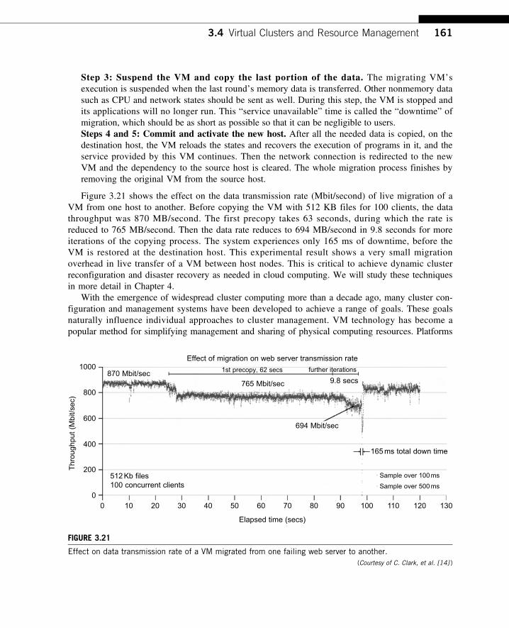
Step 3: Suspend the VM and copy the last portion of the data. The migrating VM’sexecution is suspended when the last round’s memory data is transferred. Other nonmemory datasuch as CPU and network states should be sent as well. During this step, the VM is stopped andits applications will no longer run. This “service unavailable” time is called the “downtime” ofmigration, which should be as short as possible so that it can be negligible to users.Steps 4 and 5: Commit and activate the new host. After all the needed data is copied, on thedestination host, the VM reloads the states and recovers the execution of programs in it, and theservice provided by this VM continues. Then the network connection is redirected to the newVM and the dependency to the source host is cleared. The whole migration process finishes byremoving the original VM from the source host.
Figure 3.21 shows the effect on the data transmission rate (Mbit/second) of live migration of aVM from one host to another. Before copying the VM with 512 KB files for 100 clients, the datathroughput was 870 MB/second. The first precopy takes 63 seconds, during which the rate isreduced to 765 MB/second. Then the data rate reduces to 694 MB/second in 9.8 seconds for moreiterations of the copying process. The system experiences only 165 ms of downtime, before theVM is restored at the destination host. This experimental result shows a very small migrationoverhead in live transfer of a VM between host nodes. This is critical to achieve dynamic clusterreconfiguration and disaster recovery as needed in cloud computing. We will study these techniquesin more detail in Chapter 4.
With the emergence of widespread cluster computing more than a decade ago, many cluster con-figuration and management systems have been developed to achieve a range of goals. These goalsnaturally influence individual approaches to cluster management. VM technology has become apopular method for simplifying management and sharing of physical computing resources. Platforms
Elapsed time (secs)
00
200Thr
ough
put (M
bit/s
ec)
400
600
800
1000870 Mbit/sec
765 Mbit/sec 9.8 secs
further iterations1st precopy, 62 secs
694 Mbit/sec
165ms total down time
Sample over 100ms
Sample over 500ms
Effect of migration on web server transmission rate
512Kb files100 concurrent clients
10 20 30 40 50 60 70 9080 130120110100
FIGURE 3.21
Effect on data transmission rate of a VM migrated from one failing web server to another.(Courtesy of C. Clark, et al. [14] )
3.4 Virtual Clusters and Resource Management 161
such as VMware and Xen allow multiple VMs with different operating systems and configurationsto coexist on the same physical host in mutual isolation. Clustering inexpensive computers is aneffective way to obtain reliable, scalable computing power for network services and compute-intensive applications
3.4.3 Migration of Memory, Files, and Network ResourcesSince clusters have a high initial cost of ownership, including space, power conditioning, and cool-ing equipment, leasing or sharing access to a common cluster is an attractive solution whendemands vary over time. Shared clusters offer economies of scale and more effective utilization ofresources by multiplexing. Early configuration and management systems focus on expressive andscalable mechanisms for defining clusters for specific types of service, and physically partitioncluster nodes among those types. When one system migrates to another physical node, we shouldconsider the following issues.
3.4.3.1 Memory MigrationThis is one of the most important aspects of VM migration. Moving the memory instance of a VMfrom one physical host to another can be approached in any number of ways. But traditionally, theconcepts behind the techniques tend to share common implementation paradigms. The techniquesemployed for this purpose depend upon the characteristics of application/workloads supported bythe guest OS.
Memory migration can be in a range of hundreds of megabytes to a few gigabytes in a typicalsystem today, and it needs to be done in an efficient manner. The Internet Suspend-Resume (ISR)technique exploits temporal locality as memory states are likely to have considerable overlap in thesuspended and the resumed instances of a VM. Temporal locality refers to the fact that the memorystates differ only by the amount of work done since a VM was last suspended before being initiatedfor migration.
To exploit temporal locality, each file in the file system is represented as a tree of small subfiles.A copy of this tree exists in both the suspended and resumed VM instances. The advantage of usinga tree-based representation of files is that the caching ensures the transmission of only those fileswhich have been changed. The ISR technique deals with situations where the migration of livemachines is not a necessity. Predictably, the downtime (the period during which the service isunavailable due to there being no currently executing instance of a VM) is high, compared to someof the other techniques discussed later.
3.4.3.2 File System MigrationTo support VM migration, a system must provide each VM with a consistent, location-independentview of the file system that is available on all hosts. A simple way to achieve this is to provideeach VM with its own virtual disk which the file system is mapped to and transport the contents ofthis virtual disk along with the other states of the VM. However, due to the current trend of high-capacity disks, migration of the contents of an entire disk over a network is not a viable solution.Another way is to have a global file system across all machines where a VM could be located. Thisway removes the need to copy files from one machine to another because all files are network-accessible.
162 CHAPTER 3 Virtual Machines and Virtualization of Clusters and Data Centers

A distributed file system is used in ISR serving as a transport mechanism for propagating asuspended VM state. The actual file systems themselves are not mapped onto the distributed filesystem. Instead, the VMM only accesses its local file system. The relevant VM files are explicitlycopied into the local file system for a resume operation and taken out of the local file system for asuspend operation. This approach relieves developers from the complexities of implementing severaldifferent file system calls for different distributed file systems. It also essentially disassociates theVMM from any particular distributed file system semantics. However, this decoupling means thatthe VMM has to store the contents of each VM’s virtual disks in its local files, which have to bemoved around with the other state information of that VM.
In smart copying, the VMM exploits spatial locality. Typically, people often move between thesame small number of locations, such as their home and office. In these conditions, it is possible totransmit only the difference between the two file systems at suspending and resuming locations. Thistechnique significantly reduces the amount of actual physical data that has to be moved. In situationswhere there is no locality to exploit, a different approach is to synthesize much of the state at the resum-ing site. On many systems, user files only form a small fraction of the actual data on disk. Operatingsystem and application software account for the majority of storage space. The proactive state transfersolution works in those cases where the resuming site can be predicted with reasonable confidence.
3.4.3.3 Network MigrationA migrating VM should maintain all open network connections without relying on forwardingmechanisms on the original host or on support from mobility or redirection mechanisms. To enableremote systems to locate and communicate with a VM, each VM must be assigned a virtual IPaddress known to other entities. This address can be distinct from the IP address of the host machinewhere the VM is currently located. Each VM can also have its own distinct virtual MAC address.The VMM maintains a mapping of the virtual IP and MAC addresses to their corresponding VMs. Ingeneral, a migrating VM includes all the protocol states and carries its IP address with it.
If the source and destination machines of a VM migration are typically connected to a singleswitched LAN, an unsolicited ARP reply from the migrating host is provided advertising that the IPhas moved to a new location. This solves the open network connection problem by reconfiguringall the peers to send future packets to a new location. Although a few packets that have alreadybeen transmitted might be lost, there are no other problems with this mechanism. Alternatively, ona switched network, the migrating OS can keep its original Ethernet MAC address and rely on thenetwork switch to detect its move to a new port.
Live migration means moving a VM from one physical node to another while keeping its OSenvironment and applications unbroken. This capability is being increasingly utilized in today’s enter-prise environments to provide efficient online system maintenance, reconfiguration, load balancing,and proactive fault tolerance. It provides desirable features to satisfy requirements for computingresources in modern computing systems, including server consolidation, performance isolation, andease of management. As a result, many implementations are available which support the feature usingdisparate functionalities. Traditional migration suspends VMs before the transportation and thenresumes them at the end of the process. By importing the precopy mechanism, a VM could be live-migrated without stopping the VM and keep the applications running during the migration.
Live migration is a key feature of system virtualization technologies. Here, we focus on VMmigration within a cluster environment where a network-accessible storage system, such as storage
3.4 Virtual Clusters and Resource Management 163
area network (SAN) or network attached storage (NAS), is employed. Only memory and CPU statusneeds to be transferred from the source node to the target node. Live migration techniques mainlyuse the precopy approach, which first transfers all memory pages, and then only copies modified pagesduring the last round iteratively. The VM service downtime is expected to be minimal by using iterativecopy operations. When applications’ writable working set becomes small, the VM is suspended andonly the CPU state and dirty pages in the last round are sent out to the destination.
In the precopy phase, although a VM service is still available, much performance degradation willoccur because the migration daemon continually consumes network bandwidth to transfer dirty pages ineach round. An adaptive rate limiting approach is employed to mitigate this issue, but total migration timeis prolonged by nearly 10 times. Moreover, the maximum number of iterations must be set because not allapplications’ dirty pages are ensured to converge to a small writable working set over multiple rounds.
In fact, these issues with the precopy approach are caused by the large amount of transferreddata during the whole migration process. A checkpointing/recovery and trace/replay approach (CR/TR-Motion) is proposed to provide fast VM migration. This approach transfers the execution tracefile in iterations rather than dirty pages, which is logged by a trace daemon. Apparently, the totalsize of all log files is much less than that of dirty pages. So, total migration time and downtime ofmigration are drastically reduced. However, CR/TR-Motion is valid only when the log replay rate islarger than the log growth rate. The inequality between source and target nodes limits the applica-tion scope of live migration in clusters.
Another strategy of postcopy is introduced for live migration of VMs. Here, all memory pages aretransferred only once during the whole migration process and the baseline total migration time isreduced. But the downtime is much higher than that of precopy due to the latency of fetching pagesfrom the source node before the VM can be resumed on the target. With the advent of multicore ormany-core machines, abundant CPU resources are available. Even if several VMs reside on a same mul-ticore machine, CPU resources are still rich because physical CPUs are frequently amenable to multi-plexing. We can exploit these copious CPU resources to compress page frames and the amount oftransferred data can be significantly reduced. Memory compression algorithms typically have littlememory overhead. Decompression is simple and very fast and requires no memory for decompression.
3.4.3.4 Live Migration of VM Using XenIn Section 3.2.1, we studied Xen as a VMM or hypervisor, which allows multiple commodity OSes toshare x86 hardware in a safe and orderly fashion. The following example explains how to perform livemigration of a VM between two Xen-enabled host machines. Domain 0 (or Dom0) performs tasks tocreate, terminate, or migrate to another host. Xen uses a send/recv model to transfer states across VMs.
Example 3.8 Live Migration of VMs between Two Xen-Enabled Hosts
Xen supports live migration. It is a useful feature and natural extension to virtualization platforms thatallows for the transfer of a VM from one physical machine to another with little or no downtime of theservices hosted by the VM. Live migration transfers the working state and memory of a VM across a net-work when it is running. Xen also supports VM migration by using a mechanism called Remote DirectMemory Access (RDMA).
RDMA speeds up VM migration by avoiding TCP/IP stack processing overhead. RDMA implements adifferent transfer protocol whose origin and destination VM buffers must be registered before any transfer
164 CHAPTER 3 Virtual Machines and Virtualization of Clusters and Data Centers
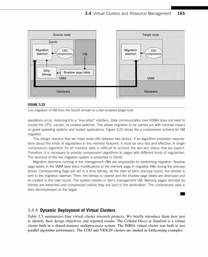
operations occur, reducing it to a “one-sided” interface. Data communication over RDMA does not need toinvolve the CPU, caches, or context switches. This allows migration to be carried out with minimal impacton guest operating systems and hosted applications. Figure 3.22 shows the a compression scheme for VMmigration.
This design requires that we make trade-offs between two factors. If an algorithm embodies expecta-tions about the kinds of regularities in the memory footprint, it must be very fast and effective. A singlecompression algorithm for all memory data is difficult to achieve the win-win status that we expect.Therefore, it is necessary to provide compression algorithms to pages with different kinds of regularities.The structure of this live migration system is presented in Dom0.
Migration daemons running in the management VMs are responsible for performing migration. Shadowpage tables in the VMM layer trace modifications to the memory page in migrated VMs during the precopyphase. Corresponding flags are set in a dirty bitmap. At the start of each precopy round, the bitmap issent to the migration daemon. Then, the bitmap is cleared and the shadow page tables are destroyed andre-created in the next round. The system resides in Xen’s management VM. Memory pages denoted bybitmap are extracted and compressed before they are sent to the destination. The compressed data isthen decompressed on the target.
3.4.4 Dynamic Deployment of Virtual ClustersTable 3.5 summarizes four virtual cluster research projects. We briefly introduce them here justto identify their design objectives and reported results. The Cellular Disco at Stanford is a virtualcluster built in a shared-memory multiprocessor system. The INRIA virtual cluster was built to testparallel algorithm performance. The COD and VIOLIN clusters are studied in forthcoming examples.
Source node Target node
Migrationdaemon
CBCcompression
Migrationdaemon
CBCcompressionVM
Dom0
Shadow page tableDirty
bitmapVMM
Hardware
VMM
Hardware
FIGURE 3.22
Live migration of VM from the Dom0 domain to a Xen-enabled target host.
3.4 Virtual Clusters and Resource Management 165
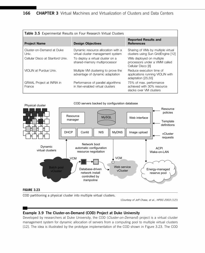
Example 3.9 The Cluster-on-Demand (COD) Project at Duke University
Developed by researchers at Duke University, the COD (Cluster-on-Demand) project is a virtual clustermanagement system for dynamic allocation of servers from a computing pool to multiple virtual clusters[12]. The idea is illustrated by the prototype implementation of the COD shown in Figure 3.23. The COD
Table 3.5 Experimental Results on Four Research Virtual Clusters
Project Name Design ObjectivesReported Results andReferences
Cluster-on-Demand at DukeUniv.
Dynamic resource allocation with avirtual cluster management system
Sharing of VMs by multiple virtualclusters using Sun GridEngine [12]
Cellular Disco at Stanford Univ. To deploy a virtual cluster on ashared-memory multiprocessor
VMs deployed on multipleprocessors under a VMM calledCellular Disco [8]
VIOLIN at Purdue Univ. Multiple VM clustering to prove theadvantage of dynamic adaptation
Reduce execution time ofapplications running VIOLIN withadaptation [25,55]
GRAAL Project at INRIA inFrance
Performance of parallel algorithmsin Xen-enabled virtual clusters
75% of max. performanceachieved with 30% resourceslacks over VM clusters
Physical clusterCOD servers backed by configuration database
Resourcepolicies
Templatedefinitions
vClusterrequests
Energy-managedreserve pool
Web servicevCluster
VCMVCM
Network bootautomatic configuration
resource negotiation
Database-drivennetwork installcontrolled bytrampoline
Batch poolvCluster
Dynamicvirtual clusters
Resourcemanager
DHCP Confd NIS MyDNS
MySQL
Image upload
Web interface
ACPIWake-on-LAN
FIGURE 3.23
COD partitioning a physical cluster into multiple virtual clusters.(Courtesy of Jeff Chase, et al., HPDC-2003 [12] )
166 CHAPTER 3 Virtual Machines and Virtualization of Clusters and Data Centers
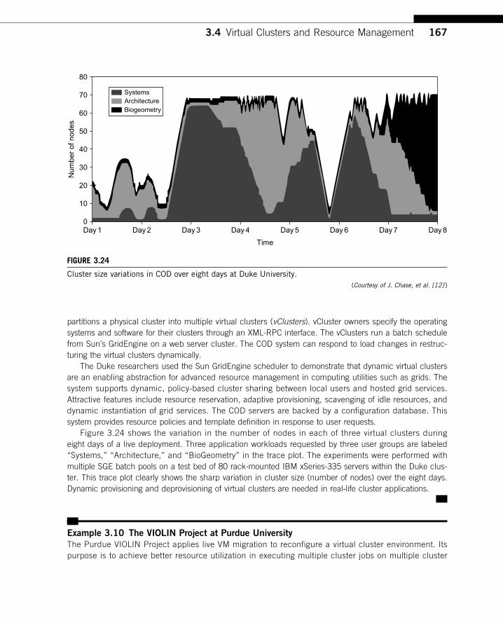
partitions a physical cluster into multiple virtual clusters (vClusters). vCluster owners specify the operatingsystems and software for their clusters through an XML-RPC interface. The vClusters run a batch schedulefrom Sun’s GridEngine on a web server cluster. The COD system can respond to load changes in restruc-turing the virtual clusters dynamically.
The Duke researchers used the Sun GridEngine scheduler to demonstrate that dynamic virtual clustersare an enabling abstraction for advanced resource management in computing utilities such as grids. Thesystem supports dynamic, policy-based cluster sharing between local users and hosted grid services.Attractive features include resource reservation, adaptive provisioning, scavenging of idle resources, anddynamic instantiation of grid services. The COD servers are backed by a configuration database. Thissystem provides resource policies and template definition in response to user requests.
Figure 3.24 shows the variation in the number of nodes in each of three virtual clusters duringeight days of a live deployment. Three application workloads requested by three user groups are labeled“Systems,” “Architecture,” and “BioGeometry” in the trace plot. The experiments were performed withmultiple SGE batch pools on a test bed of 80 rack-mounted IBM xSeries-335 servers within the Duke clus-ter. This trace plot clearly shows the sharp variation in cluster size (number of nodes) over the eight days.Dynamic provisioning and deprovisioning of virtual clusters are needed in real-life cluster applications.
Example 3.10 The VIOLIN Project at Purdue University
The Purdue VIOLIN Project applies live VM migration to reconfigure a virtual cluster environment. Itspurpose is to achieve better resource utilization in executing multiple cluster jobs on multiple cluster
Day1
80
SystemsArchitectureBiogeometry
70
60
50
40
Num
ber
of n
odes
30
20
10
0Day2 Day3 Day4
Time
Day5 Day6 Day7 Day8
FIGURE 3.24
Cluster size variations in COD over eight days at Duke University.(Courtesy of J. Chase, et al. [12] )
3.4 Virtual Clusters and Resource Management 167
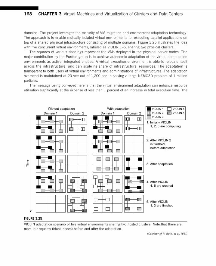
domains. The project leverages the maturity of VM migration and environment adaptation technology.The approach is to enable mutually isolated virtual environments for executing parallel applications ontop of a shared physical infrastructure consisting of multiple domains. Figure 3.25 illustrates the ideawith five concurrent virtual environments, labeled as VIOLIN 1–5, sharing two physical clusters.
The squares of various shadings represent the VMs deployed in the physical server nodes. Themajor contribution by the Purdue group is to achieve autonomic adaptation of the virtual computationenvironments as active, integrated entities. A virtual execution environment is able to relocate itselfacross the infrastructure, and can scale its share of infrastructural resources. The adaptation istransparent to both users of virtual environments and administrations of infrastructures. The adaptationoverhead is maintained at 20 sec out of 1,200 sec in solving a large NEMO3D problem of 1 millionparticles.
The message being conveyed here is that the virtual environment adaptation can enhance resourceutilization significantly at the expense of less than 1 percent of an increase in total execution time. The
With adaptation
Domain 1
Tim
e
Domain 2 Domain 1
1. Initially VIOLIN 1, 2, 3 are computing
2. After VIOLIN 2 is finished, before adaptation
4. After VIOLIN 4, 5 are created
5. After VIOLIN 1, 3 are finished
3. After adaptation
Domain 2
Without adaptation VIOLIN 1
VIOLIN 2
VIOLIN 3
VIOLIN 4
VIOLIN 5
FIGURE 3.25
VIOLIN adaptation scenario of five virtual environments sharing two hosted clusters. Note that there aremore idle squares (blank nodes) before and after the adaptation.
(Courtesy of P. Ruth, et al. [55] )
168 CHAPTER 3 Virtual Machines and Virtualization of Clusters and Data Centers
migration of VIOLIN environments does pay off. Of course, the gain in shared resource utilization will bene-fit many users, and the performance gain varies with different adaptation scenarios. We leave readers totrace the execution of another scenario in Problem 3.17 at the end of this chapter to tell the differences.Virtual networking is a fundamental component of the VIOLIN system.
3.5 VIRTUALIZATION FOR DATA-CENTER AUTOMATIONData centers have grown rapidly in recent years, and all major IT companies are pouring theirresources into building new data centers. In addition, Google, Yahoo!, Amazon, Microsoft, HP,Apple, and IBM are all in the game. All these companies have invested billions of dollars in data-center construction and automation. Data-center automation means that huge volumes of hardware,software, and database resources in these data centers can be allocated dynamically to millions ofInternet users simultaneously, with guaranteed QoS and cost-effectiveness.
This automation process is triggered by the growth of virtualization products and cloud com-puting services. From 2006 to 2011, according to an IDC 2007 report on the growth of virtuali-zation and its market distribution in major IT sectors. In 2006, virtualization has a market shareof $1,044 million in business and enterprise opportunities. The majority was dominated by pro-duction consolidation and software development. Virtualization is moving towards enhancingmobility, reducing planned downtime (for maintenance), and increasing the number of virtualclients.
The latest virtualization development highlights high availability (HA), backup services,workload balancing, and further increases in client bases. IDC projected that automation, serviceorientation, policy-based, and variable costs in the virtualization market. The total businessopportunities may increase to $3.2 billion by 2011. The major market share moves to the areasof HA, utility computing, production consolidation, and client bases. In what follows, we willdiscuss server consolidation, virtual storage, OS support, and trust management in automateddata-center designs.
3.5.1 Server Consolidation in Data CentersIn data centers, a large number of heterogeneous workloads can run on servers at various times. Theseheterogeneous workloads can be roughly divided into two categories: chatty workloads and noninter-active workloads. Chatty workloads may burst at some point and return to a silent state at some otherpoint. A web video service is an example of this, whereby a lot of people use it at night and few peo-ple use it during the day. Noninteractive workloads do not require people’s efforts to make progressafter they are submitted. High-performance computing is a typical example of this. At various stages,the requirements for resources of these workloads are dramatically different. However, to guaranteethat a workload will always be able to cope with all demand levels, the workload is statically allo-cated enough resources so that peak demand is satisfied. Figure 3.29 illustrates server virtualization ina data center. In this case, the granularity of resource optimization is focused on the CPU, memory,and network interfaces.
3.5 Virtualization for Data-Center Automation 169
Therefore, it is common that most servers in data centers are underutilized. A large amount ofhardware, space, power, and management cost of these servers is wasted. Server consolidation is anapproach to improve the low utility ratio of hardware resources by reducing the number of physicalservers. Among several server consolidation techniques such as centralized and physical consolida-tion, virtualization-based server consolidation is the most powerful. Data centers need to optimizetheir resource management. Yet these techniques are performed with the granularity of a full servermachine, which makes resource management far from well optimized. Server virtualization enablessmaller resource allocation than a physical machine.
In general, the use of VMs increases resource management complexity. This causes a challengein terms of how to improve resource utilization as well as guarantee QoS in data centers. In detail,server virtualization has the following side effects:
• Consolidation enhances hardware utilization. Many underutilized servers are consolidated intofewer servers to enhance resource utilization. Consolidation also facilitates backup services anddisaster recovery.
• This approach enables more agile provisioning and deployment of resources. In a virtualenvironment, the images of the guest OSes and their applications are readily cloned and reused.
• The total cost of ownership is reduced. In this sense, server virtualization causes deferredpurchases of new servers, a smaller data-center footprint, lower maintenance costs, and lowerpower, cooling, and cabling requirements.
• This approach improves availability and business continuity. The crash of a guest OS has noeffect on the host OS or any other guest OS. It becomes easier to transfer a VM from oneserver to another, because virtual servers are unaware of the underlying hardware.
To automate data-center operations, one must consider resource scheduling, architectural support,power management, automatic or autonomic resource management, performance of analytical mod-els, and so on. In virtualized data centers, an efficient, on-demand, fine-grained scheduler is one ofthe key factors to improve resource utilization. Scheduling and reallocations can be done in a widerange of levels in a set of data centers. The levels match at least at the VM level, server level,and data-center level. Ideally, scheduling and resource reallocations should be done at all levels.However, due to the complexity of this, current techniques only focus on a single level or, at most,two levels.
Dynamic CPU allocation is based on VM utilization and application-level QoS metrics. Onemethod considers both CPU and memory flowing as well as automatically adjusting resource over-head based on varying workloads in hosted services. Another scheme uses a two-level resourcemanagement system to handle the complexity involved. A local controller at the VM level and aglobal controller at the server level are designed. They implement autonomic resource allocation viathe interaction of the local and global controllers. Multicore and virtualization are two cutting tech-niques that can enhance each other.
However, the use of CMP is far from well optimized. The memory system of CMP is a typicalexample. One can design a virtual hierarchy on a CMP in data centers. One can consider protocolsthat minimize the memory access time, inter-VM interferences, facilitating VM reassignment, andsupporting inter-VM sharing. One can also consider a VM-aware power budgeting scheme usingmultiple managers integrated to achieve better power management. The power budgeting policiescannot ignore the heterogeneity problems. Consequently, one must address the trade-off of powersaving and data-center performance.
170 CHAPTER 3 Virtual Machines and Virtualization of Clusters and Data Centers
3.5.2 Virtual Storage ManagementThe term “storage virtualization” was widely used before the renaissance of system virtualization. Yetthe term has a different meaning in a system virtualization environment. Previously, storage virtualiza-tion was largely used to describe the aggregation and repartitioning of disks at very coarse time scalesfor use by physical machines. In system virtualization, virtual storage includes the storage managed byVMMs and guest OSes. Generally, the data stored in this environment can be classified into two cate-gories: VM images and application data. The VM images are special to the virtual environment, whileapplication data includes all other data which is the same as the data in traditional OS environments.
The most important aspects of system virtualization are encapsulation and isolation. Traditionaloperating systems and applications running on them can be encapsulated in VMs. Only one operatingsystem runs in a virtualization while many applications run in the operating system. System virtuali-zation allows multiple VMs to run on a physical machine and the VMs are completely isolated. Toachieve encapsulation and isolation, both the system software and the hardware platform, such asCPUs and chipsets, are rapidly updated. However, storage is lagging. The storage systems becomethe main bottleneck of VM deployment.
In virtualization environments, a virtualization layer is inserted between the hardware and tradi-tional operating systems or a traditional operating system is modified to support virtualization. Thisprocedure complicates storage operations. On the one hand, storage management of the guest OS per-forms as though it is operating in a real hard disk while the guest OSes cannot access the hard diskdirectly. On the other hand, many guest OSes contest the hard disk when many VMs are running on asingle physical machine. Therefore, storage management of the underlying VMM is much more com-plex than that of guest OSes (traditional OSes).
In addition, the storage primitives used by VMs are not nimble. Hence, operations such as remap-ping volumes across hosts and checkpointing disks are frequently clumsy and esoteric, and sometimessimply unavailable. In data centers, there are often thousands of VMs, which cause the VM images tobecome flooded. Many researchers tried to solve these problems in virtual storage management. Themain purposes of their research are to make management easy while enhancing performance and redu-cing the amount of storage occupied by the VM images. Parallax is a distributed storage system custo-mized for virtualization environments. Content Addressable Storage (CAS) is a solution to reduce thetotal size of VM images, and therefore supports a large set of VM-based systems in data centers.
Since traditional storage management techniques do not consider the features of storage in virtualizationenvironments, Parallax designs a novel architecture in which storage features that have traditionally beenimplemented directly on high-end storage arrays and switchers are relocated into a federation of storageVMs. These storage VMs share the same physical hosts as the VMs that they serve. Figure 3.30 providesan overview of the Parallax system architecture. It supports all popular system virtualization techniques,such as paravirtualization and full virtualization. For each physical machine, Parallax customizes a specialstorage appliance VM. The storage appliance VM acts as a block virtualization layer between individualVMs and the physical storage device. It provides a virtual disk for each VM on the same physical machine.
Example 3.11 Parallax Providing Virtual Disks to Client VMs from a Large Common
Shared Physical Disk
The architecture of Parallax is scalable and especially suitable for use in cluster-based environments.Figure 3.26 shows a high-level view of the structure of a Parallax-based cluster. A cluster-wide administrativedomain manages all storage appliance VMs, which makes storage management easy. The storage appliance
3.5 Virtualization for Data-Center Automation 171
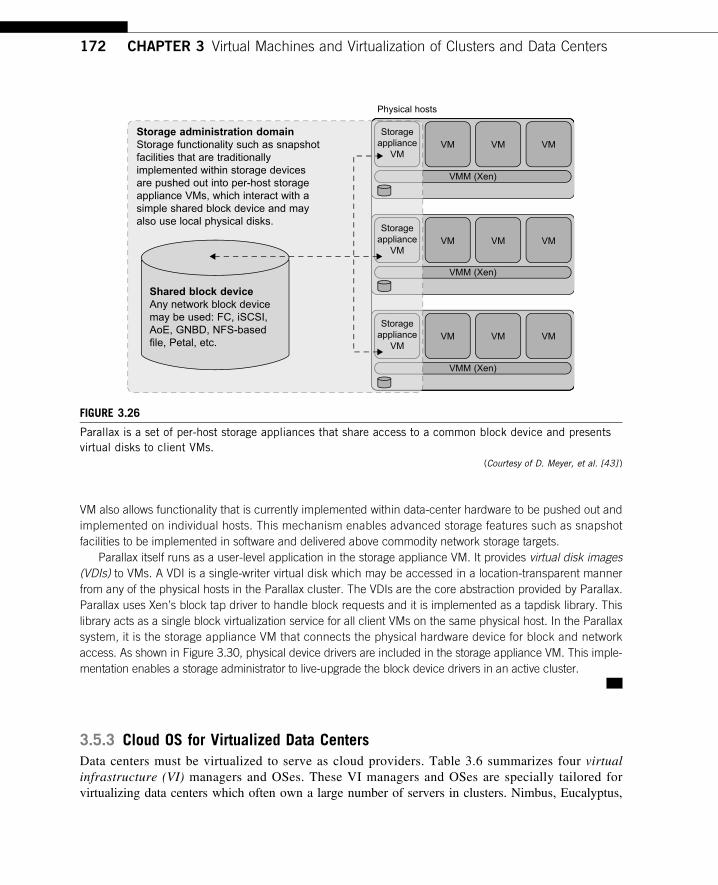
VM also allows functionality that is currently implemented within data-center hardware to be pushed out andimplemented on individual hosts. This mechanism enables advanced storage features such as snapshotfacilities to be implemented in software and delivered above commodity network storage targets.
Parallax itself runs as a user-level application in the storage appliance VM. It provides virtual disk images(VDIs) to VMs. A VDI is a single-writer virtual disk which may be accessed in a location-transparent mannerfrom any of the physical hosts in the Parallax cluster. The VDIs are the core abstraction provided by Parallax.Parallax uses Xen’s block tap driver to handle block requests and it is implemented as a tapdisk library. Thislibrary acts as a single block virtualization service for all client VMs on the same physical host. In the Parallaxsystem, it is the storage appliance VM that connects the physical hardware device for block and networkaccess. As shown in Figure 3.30, physical device drivers are included in the storage appliance VM. This imple-mentation enables a storage administrator to live-upgrade the block device drivers in an active cluster.
3.5.3 Cloud OS for Virtualized Data CentersData centers must be virtualized to serve as cloud providers. Table 3.6 summarizes four virtualinfrastructure (VI) managers and OSes. These VI managers and OSes are specially tailored forvirtualizing data centers which often own a large number of servers in clusters. Nimbus, Eucalyptus,
Storageappliance
VM
Physical hosts
VM
VMM (Xen)
VMM (Xen)
VMM (Xen)
VM VM
Storageappliance
VMVM VM VM
Storageappliance
VMVM VM VM
Storage administration domainStorage functionality such as snapshotfacilities that are traditionallyimplemented within storage devicesare pushed out into per-host storageappliance VMs, which interact with asimple shared block device and mayalso use local physical disks.
Shared block deviceAny network block devicemay be used: FC, iSCSI,AoE, GNBD, NFS-basedfile, Petal, etc.
FIGURE 3.26
Parallax is a set of per-host storage appliances that share access to a common block device and presentsvirtual disks to client VMs.
(Courtesy of D. Meyer, et al. [43] )
172 CHAPTER 3 Virtual Machines and Virtualization of Clusters and Data Centers
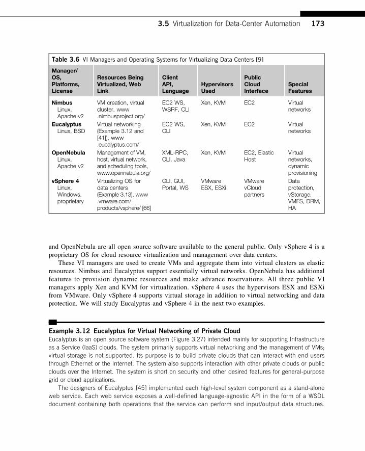
and OpenNebula are all open source software available to the general public. Only vSphere 4 is aproprietary OS for cloud resource virtualization and management over data centers.
These VI managers are used to create VMs and aggregate them into virtual clusters as elasticresources. Nimbus and Eucalyptus support essentially virtual networks. OpenNebula has additionalfeatures to provision dynamic resources and make advance reservations. All three public VImanagers apply Xen and KVM for virtualization. vSphere 4 uses the hypervisors ESX and ESXifrom VMware. Only vSphere 4 supports virtual storage in addition to virtual networking and dataprotection. We will study Eucalyptus and vSphere 4 in the next two examples.
Example 3.12 Eucalyptus for Virtual Networking of Private Cloud
Eucalyptus is an open source software system (Figure 3.27) intended mainly for supporting Infrastructureas a Service (IaaS) clouds. The system primarily supports virtual networking and the management of VMs;virtual storage is not supported. Its purpose is to build private clouds that can interact with end usersthrough Ethernet or the Internet. The system also supports interaction with other private clouds or publicclouds over the Internet. The system is short on security and other desired features for general-purposegrid or cloud applications.
The designers of Eucalyptus [45] implemented each high-level system component as a stand-aloneweb service. Each web service exposes a well-defined language-agnostic API in the form of a WSDLdocument containing both operations that the service can perform and input/output data structures.
Table 3.6 VI Managers and Operating Systems for Virtualizing Data Centers [9]
Manager/OS,Platforms,License
Resources BeingVirtualized, WebLink
ClientAPI,Language
HypervisorsUsed
PublicCloudInterface
SpecialFeatures
NimbusLinux,Apache v2
VM creation, virtualcluster, www.nimbusproject.org/
EC2 WS,WSRF, CLI
Xen, KVM EC2 Virtualnetworks
EucalyptusLinux, BSD
Virtual networking(Example 3.12 and[41]), www.eucalyptus.com/
EC2 WS,CLI
Xen, KVM EC2 Virtualnetworks
OpenNebulaLinux,Apache v2
Management of VM,host, virtual network,and scheduling tools,www.opennebula.org/
XML-RPC,CLI, Java
Xen, KVM EC2, ElasticHost
Virtualnetworks,dynamicprovisioning
vSphere 4Linux,Windows,proprietary
Virtualizing OS fordata centers(Example 3.13), www.vmware.com/products/vsphere/ [66]
CLI, GUI,Portal, WS
VMwareESX, ESXi
VMwarevCloudpartners
Dataprotection,vStorage,VMFS, DRM,HA
3.5 Virtualization for Data-Center Automation 173
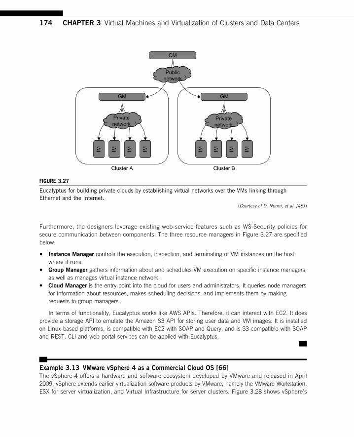
Furthermore, the designers leverage existing web-service features such as WS-Security policies forsecure communication between components. The three resource managers in Figure 3.27 are specifiedbelow:
• Instance Manager controls the execution, inspection, and terminating of VM instances on the hostwhere it runs.
• Group Manager gathers information about and schedules VM execution on specific instance managers,as well as manages virtual instance network.
• Cloud Manager is the entry-point into the cloud for users and administrators. It queries node managersfor information about resources, makes scheduling decisions, and implements them by makingrequests to group managers.
In terms of functionality, Eucalyptus works like AWS APIs. Therefore, it can interact with EC2. It doesprovide a storage API to emulate the Amazon S3 API for storing user data and VM images. It is installedon Linux-based platforms, is compatible with EC2 with SOAP and Query, and is S3-compatible with SOAPand REST. CLI and web portal services can be applied with Eucalyptus.
Example 3.13 VMware vSphere 4 as a Commercial Cloud OS [66]
The vSphere 4 offers a hardware and software ecosystem developed by VMware and released in April2009. vSphere extends earlier virtualization software products by VMware, namely the VMware Workstation,ESX for server virtualization, and Virtual Infrastructure for server clusters. Figure 3.28 shows vSphere’s
CM
GM
Publicnetwork
Privatenetwork
Cluster A Cluster B
GM
Privatenetwork
IM IM IM IM IM IM IM IM
FIGURE 3.27
Eucalyptus for building private clouds by establishing virtual networks over the VMs linking throughEthernet and the Internet.
(Courtesy of D. Nurmi, et al. [45] )
174 CHAPTER 3 Virtual Machines and Virtualization of Clusters and Data Centers
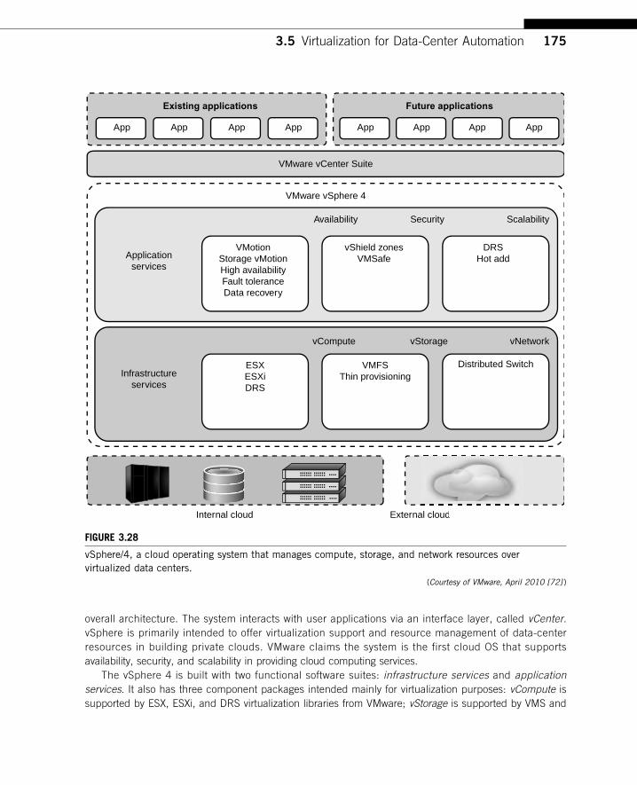
overall architecture. The system interacts with user applications via an interface layer, called vCenter.vSphere is primarily intended to offer virtualization support and resource management of data-centerresources in building private clouds. VMware claims the system is the first cloud OS that supportsavailability, security, and scalability in providing cloud computing services.
The vSphere 4 is built with two functional software suites: infrastructure services and applicationservices. It also has three component packages intended mainly for virtualization purposes: vCompute issupported by ESX, ESXi, and DRS virtualization libraries from VMware; vStorage is supported by VMS and
Future applications
Security ScalabilityAvailability
Applicationservices
VMotionStorage vMotionHigh availabilityFault toleranceData recovery
ESXESXiDRS
VMFSThin provisioning
Distributed Switch
vNetworkvStoragevCompute
Internal cloud External cloud
vShield zonesVMSafe
DRSHot add
Infrastructureservices
Existing applications
App App App App App App App App
al cloud
VMware vSphere 4
VMware vCenter Suite
FIGURE 3.28
vSphere/4, a cloud operating system that manages compute, storage, and network resources overvirtualized data centers.
(Courtesy of VMware, April 2010 [72] )
3.5 Virtualization for Data-Center Automation 175
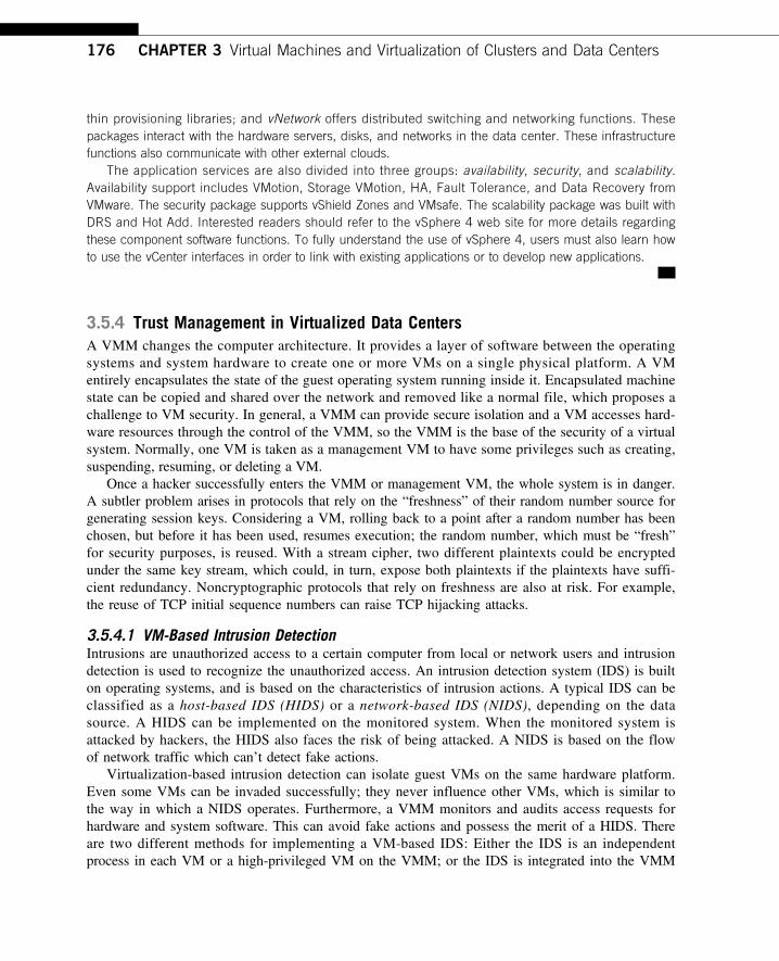
thin provisioning libraries; and vNetwork offers distributed switching and networking functions. Thesepackages interact with the hardware servers, disks, and networks in the data center. These infrastructurefunctions also communicate with other external clouds.
The application services are also divided into three groups: availability, security, and scalability.Availability support includes VMotion, Storage VMotion, HA, Fault Tolerance, and Data Recovery fromVMware. The security package supports vShield Zones and VMsafe. The scalability package was built withDRS and Hot Add. Interested readers should refer to the vSphere 4 web site for more details regardingthese component software functions. To fully understand the use of vSphere 4, users must also learn howto use the vCenter interfaces in order to link with existing applications or to develop new applications.
3.5.4 Trust Management in Virtualized Data CentersA VMM changes the computer architecture. It provides a layer of software between the operatingsystems and system hardware to create one or more VMs on a single physical platform. A VMentirely encapsulates the state of the guest operating system running inside it. Encapsulated machinestate can be copied and shared over the network and removed like a normal file, which proposes achallenge to VM security. In general, a VMM can provide secure isolation and a VM accesses hard-ware resources through the control of the VMM, so the VMM is the base of the security of a virtualsystem. Normally, one VM is taken as a management VM to have some privileges such as creating,suspending, resuming, or deleting a VM.
Once a hacker successfully enters the VMM or management VM, the whole system is in danger.A subtler problem arises in protocols that rely on the “freshness” of their random number source forgenerating session keys. Considering a VM, rolling back to a point after a random number has beenchosen, but before it has been used, resumes execution; the random number, which must be “fresh”for security purposes, is reused. With a stream cipher, two different plaintexts could be encryptedunder the same key stream, which could, in turn, expose both plaintexts if the plaintexts have suffi-cient redundancy. Noncryptographic protocols that rely on freshness are also at risk. For example,the reuse of TCP initial sequence numbers can raise TCP hijacking attacks.
3.5.4.1 VM-Based Intrusion DetectionIntrusions are unauthorized access to a certain computer from local or network users and intrusiondetection is used to recognize the unauthorized access. An intrusion detection system (IDS) is builton operating systems, and is based on the characteristics of intrusion actions. A typical IDS can beclassified as a host-based IDS (HIDS) or a network-based IDS (NIDS), depending on the datasource. A HIDS can be implemented on the monitored system. When the monitored system isattacked by hackers, the HIDS also faces the risk of being attacked. A NIDS is based on the flowof network traffic which can’t detect fake actions.
Virtualization-based intrusion detection can isolate guest VMs on the same hardware platform.Even some VMs can be invaded successfully; they never influence other VMs, which is similar tothe way in which a NIDS operates. Furthermore, a VMM monitors and audits access requests forhardware and system software. This can avoid fake actions and possess the merit of a HIDS. Thereare two different methods for implementing a VM-based IDS: Either the IDS is an independentprocess in each VM or a high-privileged VM on the VMM; or the IDS is integrated into the VMM
176 CHAPTER 3 Virtual Machines and Virtualization of Clusters and Data Centers
and has the same privilege to access the hardware as well as the VMM. Garfinkel and Rosenblum[17] have proposed an IDS to run on a VMM as a high-privileged VM. Figure 3.29 illustratesthe concept.
The VM-based IDS contains a policy engine and a policy module. The policy framework canmonitor events in different guest VMs by operating system interface library and PTrace indicatestrace to secure policy of monitored host. It’s difficult to predict and prevent all intrusions withoutdelay. Therefore, an analysis of the intrusion action is extremely important after an intrusion occurs.At the time of this writing, most computer systems use logs to analyze attack actions, but it is hard toensure the credibility and integrity of a log. The IDS log service is based on the operating system ker-nel. Thus, when an operating system is invaded by attackers, the log service should be unaffected.
Besides IDS, honeypots and honeynets are also prevalent in intrusion detection. They attract andprovide a fake system view to attackers in order to protect the real system. In addition, the attackaction can be analyzed, and a secure IDS can be built. A honeypot is a purposely defective systemthat simulates an operating system to cheat and monitor the actions of an attacker. A honeypot canbe divided into physical and virtual forms. A guest operating system and the applications runningon it constitute a VM. The host operating system and VMM must be guaranteed to prevent attacksfrom the VM in a virtual honeypot.
Example 3.14 EMC Establishment of Trusted Zones for Protection of Virtual Clusters
Provided to Multiple Tenants
EMC and VMware have joined forces in building security middleware for trust management in distribu-ted systems and private clouds. The concept of trusted zones was established as part of the virtualinfrastructure. Figure 3.30 illustrates the concept of creating trusted zones for virtual clusters (multiple
Monitored host
APP APP
Guest OS
PTrace
Virtual machine
IDS
Virtual machine monitor
OS interface library
Policyframework
Policy engine
Policy module
FIGURE 3.29
The architecture of livewire for intrusion detection using a dedicated VM.(Courtesy of Garfinkel and Rosenblum, 2002 [17] )
3.5 Virtualization for Data-Center Automation 177
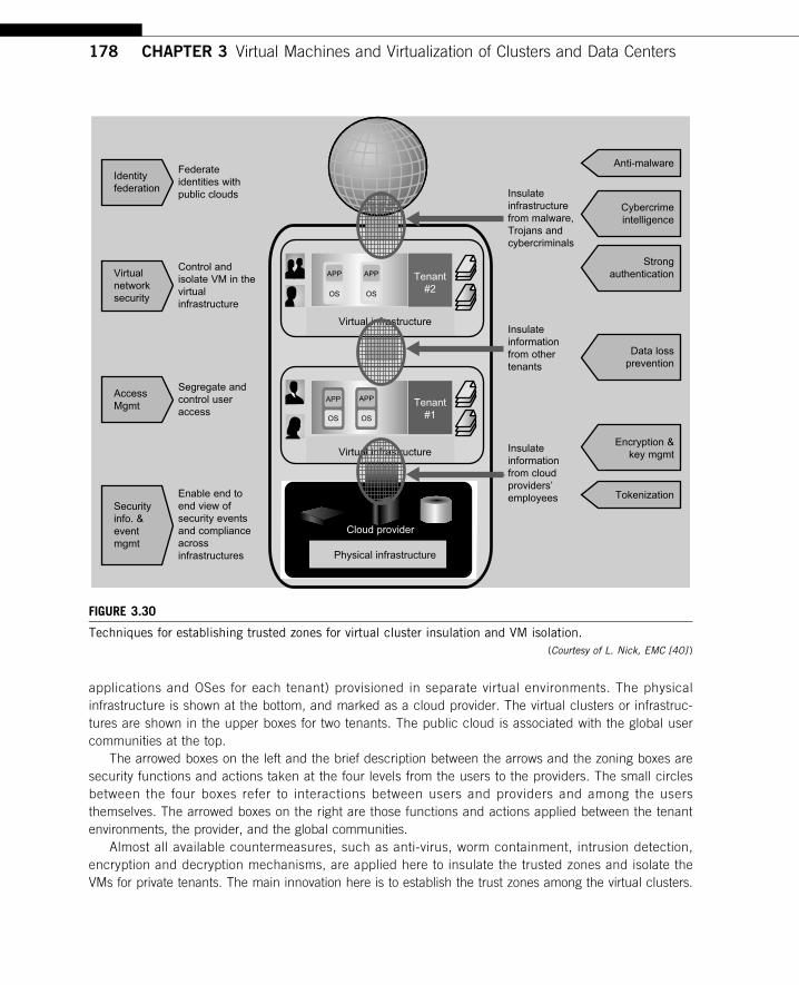
applications and OSes for each tenant) provisioned in separate virtual environments. The physicalinfrastructure is shown at the bottom, and marked as a cloud provider. The virtual clusters or infrastruc-tures are shown in the upper boxes for two tenants. The public cloud is associated with the global usercommunities at the top.
The arrowed boxes on the left and the brief description between the arrows and the zoning boxes aresecurity functions and actions taken at the four levels from the users to the providers. The small circlesbetween the four boxes refer to interactions between users and providers and among the usersthemselves. The arrowed boxes on the right are those functions and actions applied between the tenantenvironments, the provider, and the global communities.
Almost all available countermeasures, such as anti-virus, worm containment, intrusion detection,encryption and decryption mechanisms, are applied here to insulate the trusted zones and isolate theVMs for private tenants. The main innovation here is to establish the trust zones among the virtual clusters.
Federateidentities withpublic clouds
Identityfederation
Virtualnetworksecurity
AccessMgmt
Segregate andcontrol useraccess
Enable end toend view ofsecurity eventsand complianceacrossinfrastructures
Insulateinformationfrom cloudproviders’employees
Insulateinformationfrom othertenants
Insulateinfrastructurefrom malware,Trojans andcybercriminals
Anti-malware
Cybercrimeintelligence
Strongauthentication
Data lossprevention
Encryption &key mgmt
TokenizationSecurityinfo. &eventmgmt
Control andisolate VM in thevirtualinfrastructure
Virtual infrastructure
Virtual infrastructure
Physical infrastructure
Cloud provider
Tenant#2
Tenant#1
APP APP
OS OS
APP APP
OS OS
FIGURE 3.30
Techniques for establishing trusted zones for virtual cluster insulation and VM isolation.(Courtesy of L. Nick, EMC [40] )
178 CHAPTER 3 Virtual Machines and Virtualization of Clusters and Data Centers
The end result is to enable an end-to-end view of security events and compliance across the virtualclusters dedicated to different tenants. We will discuss security and trust issues in Chapter 7 when westudy clouds in more detail.
3.6 BIBLIOGRAPHIC NOTES AND HOMEWORK PROBLEMSGood reviews on virtualization technology can be found in Rosenblum, et al. [53,54] and in Smithand Nair [58,59]. White papers at [71,72] report on virtualization products at VMware, includingthe vSphere 4 cloud operating system. The Xen hypervisor was introduced in [7,13,42] and KVMin [31]. Qian, et al. [50] have given some theoretical treatment of the subject. ISA-level virtualiza-tion and binary translation techniques are treated in [3] and in Smith and Nair [58]. Some compari-son of virtualizing software environments can be found in Buyya, et al. [9]. Hardware-levelvirtualization is treated in [1,7,8,13,37,43,54,67]. Intel’s support of hardware-level virtualization istreated in [62]. Some entries in Table 3.5 are taken from Buyya, et al. [9].
For GPU computing on VMs, the readers are referred to [57]. The x86 host virtualizationis treated in [2]. Pentium virtualization is treated in [53]. treated in [11,24,26,52]. I/O virtualization is
Sun Microsystems reports on OS-level virtualization in [64]. OpenVZ is introduced in its user’sguide [65]. Virtualization in Windows NT machines is described in [77,78]. For GPU computing onVMs, readers are referred to [53]. The x86 host virtualization is treated in [2]. Pentium virtualizationis treated in [53]. The book [24] have a good coverage of hardware support for virtualization. Virtualclusters are treated in [8,12,20,25,49,55,56]. In particular, Duke’s COD is reported in [12] andPurdue’s Violin in [25,55]. Memory virtualization is treated in [1,10,13,51,58,68].
Hardware-level virtualization is treated in [1,7,8,13,41,47,58,73]. Intel’s support of hardware-levelvirtualization is treated in [68]. Wells, et al. [74] have studied multi-core virtualization.The integration of multi-core and virtualization on future CPU/GPU chips posts a very hot researcharea, called asymmetric CMP as reported in [33,39,63,66,74]. Architectural supports for virtualizedchip multiprocessors have been also studied in [17,28,30,39,66]. The maturity of this co-design CMPapproach will greatly impact the future development of HPC and HTC systems.
Server consolidation in virtualized data centers is treated in [29,39,75]. Power consumption in virtua-lized data centers is treated in [44,46]. Literatures [46,60,61,62] discussed the virtual resource managementin data centers. Kochut gives an analytical model for virtualized data centers [32]. Security protection andtrust management for virtualized data centers are treated in [18,45]. For virtual storage, readers are referredto the literature [27,36,43,48,76,79]. Specific references for the examples are identified in the figure cap-tions or in the text description of the example. The Eucalyptus was reported in [45], vSphere in [72], Par-allax in [43]. The vCUDA was reported in [57] for CUDA programming on the VMs.
AcknowledgmentsThis chapter is coauthored by Zhibin Yu of Huazhong University of Science and Technology(HUST), China and by Kai Hwang of USC. Dr. Hai Jin and Dr. Xiaofei Liao of HUST have extendedsignificant technical support to this work. The authors would like to thank Dr. Zhong-Yuan Qin
Acknowledgments 179
of Southeast University, China, Fan Zhang of Tsinghua University, and Lizhong Chen and Zhou Zhaoof USC for their assistance in drawing several sketched figures and updating the references inthis chapter.
References[1] Advanced Micro Devices. AMD Secure Virtual Machine Architecture Reference Manual, 2008.[2] K. Adams, O. Agesen, A comparison of software and hardware techniques for x86 virtualization, in:
Proceedings of the 12th International Conference on Architectural Support for Programming Languagesand Operating Systems, San Jose, CA, October 2006, pp. 21–25.
[3] V. Adve, C. Lattner, et al., LLVA: A low-level virtual instruction set architecture, in: Proceedings of the36th International Symposium on Micro-architecture (MICRO-36 ’03), 2003.
[4] J. Alonso, L. Silva, A. Andrzejak, P. Silva, J. Torres, High-available grid services through the use ofvirtualized clustering, in: Proceedings of the 8th Grid Computing Conference, 2007.
[5] P. Anedda, M. Gaggero, et al., A general service-oriented approach for managing virtual machine alloca-tion, in: Proceedings of the 24th Annual ACM Symposium on Applied Computing (SAC 2009), ACMPress, March 2009, pp. 9–12.
[6] H. Andre Lagar-Cavilla, J.A. Whitney, A. Scannell, et al., SnowFlock: rapid virtual machine cloning forcloud computing, in: Proceedings of EuroSystems, 2009.
[7] P. Barham, B. Dragovic, K. Fraser, et al., Xen and the art of virtualization, in: Proceedings of the 19thACM Symposium on Operating System Principles (SOSP19), ACM Press, 2003, pp. 164–177.
[8] E. Bugnion, S. Devine, M. Rosenblum, Disco: running commodity OS on scalable multiprocessors, in:Proceedings of SOSP, 1997.
[9] R. Buyya, J. Broberg, A. Goscinski (Eds.), Cloud Computing: Principles and Paradigms, Wiley Press,New York, 2011.
[10] V. Chadha, R. Illikkal, R. Iyer, I/O Processing in a virtualized platform: a simulation-driven approach, in:Proceedings of the 3rd International Conference on Virtual Execution Environments (VEE), 2007.
[11] R. Chandra, N. Zeldovich, C. Sapuntzakis, M.S. Lam, The collective: a cache-based system managementarchitecture, in: Proceedings of the Second Symposium on Networked Systems Design and Implementa-tion (NSDI ’05), USENIX, Boston, May 2005, pp. 259–272.
[12] J. Chase, L. Grit, D. Irwin, J. Moore, S. Sprenkle, Dynamic virtual cluster in a grid site manager, in: IEEEInt’l Symp. on High Performance Distributed Computing, (HPDC-12), 2003.
[13] D. Chisnall, The Definitive Guide to the Xen Hypervisor, Prentice Hall, International, 2007.[14] C. Clark, K. Fraser, S. Hand, et al., Live migration of virtual machines, in: Proceedings of the Second
Symposium on Networked Systems Design and Implementation (NSDI ’05), 2005, pp. 273–286.[15] Y. Dong, J. Dai, et al., Towards high-quality I/O virtualization, in: Proceedings of SYSTOR 2009, The
Israeli Experimental Systems Conference, 2009.[16] E. Elnozahy, M. Kistler, R. Rajamony, Energy-efficient server clusters, in: Proceedings of the 2nd Work-
shop on Power-Aware Computing Systems, February 2002.[17] J. Frich, et al., On the potential of NoC virtualization for multicore chips, in: IEEE Int’l Conf. on
Complex, Intelligent and Software-Intensive Systems, 2008, pp. 801–807.[18] T. Garfinkel, M. Rosenblum, A virtual machine introspection-based architecture for intrusion detection,
2002.[19] L. Grit, D. Irwin, A. Yumerefendi, J. Chase, Virtual machine hosting for networked clusters: building the
foundations for autonomic orchestration, in: First International Workshop on Virtualization Technology inDistributed Computing (VTDC), November 2006.
180 CHAPTER 3 Virtual Machines and Virtualization of Clusters and Data Centers
[20] D. Gupta, S. Lee, M. Vrable, et al., Difference engine: Harnessing memory redundancy in virtualmachines, in: Proceedings of the USENIX Symposium on Operating Systems Design and Implementation(OSDI ’08), 2008, pp. 309–322.
[21] M. Hines, K. Gopalan, Post-copy based live virtual machine migration using adaptive pre-paging anddynamic self-ballooning, in: Proceedings of the ACM/USENIX International Conference on VirtualExecution Environments (VEE ’09), 2009, pp. 51–60.
[22] T. Hirofuchi, H. Nakada, et al., A live storage migration mechanism over WAN and its performance eva-luation, in: Proceedings of the 4th International Workshop on Virtualization Technologies in DistributedComputing, 15 June, ACM Press, Barcelona, Spain, 2009.
[23] K. Hwang, D. Li, Trusted cloud computing with secure resources and data coloring, IEEE InternetComput., (September/October) (2010) 30–39.
[24] Intel Open Source Technology Center, System Virtualization—Principles and Implementation, TsinghuaUniversity Press, Beijing, China, 2009.
[25] X. Jiang, D. Xu, VIOLIN: Virtual internetworking on overlay infrastructure, in: Proceedings of theInternational Symposium on Parallel and Distributed Processing and Applications, 2004, pp. 937–946.
[26] H. Jin, L. Deng, S. Wu, X. Shi, X. Pan, Live virtual machine migration with adaptive memory compres-sion, in: Proceedings of the IEEE International Conference on Cluster Computing, 2009.
[27] K. Jin, E. Miller, The effectiveness of deduplication on virtual machine disk images, in: Proceedings ofSYSTOR, 2009, The Israeli Experimental Systems Conference, 2009.
[28] S. Jones, A. Arpaci-Disseau, R. Arpaci-Disseau, Geiger: Monitoring the buffer cache in a virtual machineenvironment, in: ACM ASPLOS, San Jose, CA, October 2006, pp. 13–14.
[29] F. Kamoun, Virtualizing the datacenter without compromising server performance, ACM Ubiquity 2009,(9) (2009).
[30] D. Kim, H. Kim, J. Huh, Virtual snooping: Filtering snoops in virtualized multi-coures, in: 43rd AnnualIEEE/ACM Int’l Symposium on Mcrosrchitecture (MICRO-43).
[31] A. Kivity, et al., KVM: The linux virtual machine monitor, in: Proceedings of the Linux Symposium,Ottawa, Canada, 2007, p. 225.
[32] A. Kochut, On impact of dynamic virtual machine reallocation on data center efficiency, in: Proceedingsof the IEEE International Symposium on Modeling, Analysis and Simulation of Computers and Telecom-munication Systems (MASCOTS), 2008.
[33] R. Kumar, et al., Heterogeneous chip multiptiprocessors, IEEE Comput. Mag. 38 (November) (2005)32–38.
[34] B. Kyrre, Managing large networks of virtual machines, in: Proceedings of the 20th Large InstallationSystem Administration Conference, 2006, pp. 205–214.
[35] J. Lange, P. Dinda, Transparent network services via a virtual traffic layer for virtual machines, in:Proceedings of High Performance Distributed Computing, ACM Press, Monterey, CA, pp. 25–29,June 2007.
[36] A. Liguori, E. Hensbergen, Experiences with content addressable storage and virtual disks, in: Proceedingsof the Workshop on I/O Virtualization (WIOV ’08), 2008.
[37] H. Liu, H. Jin, X. Liao, L. Hu, C. Yu, Live migration of virtual machine based on full system trace andreplay, in: Proceedings of the 18th International Symposium on High Performance Distributed Computing(HPDC ’09), 2009, pp. 101–110.
[38] A. Mainwaring, D. Culler, Design challenges of virtual networks: Fast, general-purpose communication,in: Proceedings of the Seventh ACM SIGPLAN Symposium on Principles and Practices of ParallelProgramming, 1999.
[39] M. Marty, M. Hill, Virtual hierarchies to support server consolidation, in: Proceedings of the 34th AnnualInternational Symposium on Computer Architecture (ISCA), 2007.
References 181
[40] M. McNett, D. Gupta, A. Vahdat, G.M. Voelker, Usher: An extensible framework for managing clustersof virtual machines, in: 21st Large Installation System Administration Conference (LISA) 2007.
[41] D. Menasce, Virtualization: Concepts, applications., performance modeling, in: Proceedings of the 31stInternational Computer Measurement Group Conference, 2005, pp. 407–414.
[42] A. Menon, J. Renato, Y. Turner, Diagnosing performance overheads in the Xen virtual machine environ-ment, in: Proceedings of the 1st ACM/USENIX International Conference on Virtual Execution Environ-ments, 2005.
[43] D. Meyer, et al., Parallax: Virtual disks for virtual machines, in: Proceedings of EuroSys, 2008.[44] J. Nick, Journey to the private cloud: Security and compliance, in: Technical presentation by EMC Visit-
ing Team, May 25, Tsinghua University, Beijing, 2010.[45] D. Nurmi, et al., The eucalyptus open-source cloud computing system, in: Proceedings of the 9th
IEEE ACM International Symposium on Cluster Computing and The Grid (CCGrid), Shanghai, China,September 2009, pp. 124–131.
[46] P. Padala, et al., Adaptive control of virtualized resources in utility computing environments, in: Proceed-ings of EuroSys 2007.
[47] L. Peterson, A. Bavier, M.E. Fiuczynski, S. Muir, Experiences Building PlanetLab, in: Proceedings of the7th USENIX Symposium on Operating Systems Design and Implementation (OSDI2006), 6–8 November2006.
[48] B. Pfaff, T. Garfinkel, M. Rosenblum, Virtualization aware file systems: Getting beyond the limitations ofvirtual disks, in: Proceedings of USENIX Networked Systems Design and Implementation (NSDI 2006),May 2006, pp. 353–366.
[49] E. Pinheiro, R. Bianchini, E. Carrera, T. Heath, Dynamic cluster reconfiguration for power andperformance, in: L. Benini (Ed.), Compilers and Operating Systems for Low Power, Kluwer AcademicPublishers, 2003.
[50] H. Qian, E. Miller, et al., Agility in virtualized utility computing, in: Proceedings of the Third InternationalWorkshop on Virtualization Technology in Distributed Computing (VTDC 2007), 12 November 2007.
[51] H. Raj, I. Ganev, K. Schwan, Self-Virtualized I/O: High Performance, Scalable I/O Virtualization inMulti-core Systems, Technical Report GIT-CERCS-06-02, CERCS, Georgia Tech, 2006, www.cercs.gatech.edu/tech-reports/tr2006/git-cercs-06-02.pdf.
[52] J. Robin, C. Irvine, Analysis of the Intel pentium’s ability to support a secure virtual machine monitor, in:Proceedings of the 9th USENIX Security Symposium Vol. 9, 2000.
[53] M. Rosenblum, The reincarnation of virtual machines, ACM QUEUE, (July/August) (2004).[54] M. Rosenblum, T. Garfinkel, Virtual machine monitors: current technology and future trends, IEEE
Comput 38 (5) (2005) 39–47.[55] P. Ruth, et al., Automatic Live Migration of Virtual Computational Environments in a Multi-domain
Infrastructure, Purdue University, 2006.[56] C. Sapuntzakis, R. Chandra, B. Pfaff, et al., Optimizing the migration of virtual computers, in:
Proceedings of the 5th Symposium on Operating Systems Design and Implementation, Boston, 9–11December 2002.
[57] L. Shi, H. Chen, J. Sun, vCUDA: GPU accelerated high performance computing in virtual machines, in:Proceedings of the IEEE International Symposium on Parallel and Distributed Processing, 2009.
[58] J. Smith, R. Nair, Virtual Machines: Versatile Platforms for Systems and Processes, Morgan Kaufmann, 2005.[59] J. Smith, R. Nair, The architecture of virtual machines, IEEE Comput., (May) (2005).[60] Y. Song, H. Wang, et al., Multi-tiered on-demand resource scheduling for VM-based data center, in:
Proceedings of the 9th IEEE/ACM International Symposium on Cluster Computing and the Grid, 2009.[61] B. Sotomayor, K. Keahey, I. Foster, Combining batch execution and leasing using virtual machines, in:
Proceedings of the 17th International Symposium on High-Performance Distributed Computing, 2008.
182 CHAPTER 3 Virtual Machines and Virtualization of Clusters and Data Centers
[62] M. Steinder, I. Whalley, et al., Server virtualization in autonomic management of heterogeneousworkloads, ACM SIGOPS Oper. Syst. Rev. 42 (1) (2008) 94–95.
[63] M. Suleman, Y. Patt, E. Sprangle, A. Rohillah, Asymmetric chip multiprocessors: balancing hardware effi-ciency and programming efficiency, (2007).
[64] Sun Microsystems. Solaris Containers: Server Virtualization and Manageability, Technical white paper,September 2004.
[65] SWsoft, Inc. OpenVZ User’s Guide, http://ftp.openvz.org/doc/OpenVZ-Users-Guide.pdf, 2005.[66] F. Trivino, et al., Virtualizing netwoirk on chip resources in chip multiprocessors, J. Microprocess.
Microsyst. 35 (2010). 245–230 http://www.elsevier.com/locate/micro.[67] J. Xu, M. Zhao, et al., On the use of fuzzy modeling in virtualized datacenter management, in: Proceed-
ings of the 4th International Conference on Autonomic Computing (ICAC07), 2007.[68] R. Ublig, et al., Intel virtualization technology, IEEE Comput., (May) (2005).[69] H. Van, F. Tran, Autonomic virtual resource management for service hosting platforms, CLOUD
(2009).[70] A. Verma, P. Ahuja, A. Neogi, pMapper: Power and migration cost aware application placement in
virtualized systems, in: Proceedings of the 9th International Middleware Conference, 2008, pp. 243–264.[71] VMware (white paper). Understanding Full Virtualization, Paravirtualization, and Hardware Assist,
www.vmware.com/files/pdf/VMware_paravirtualization.pdf.[72] VMware (white paper). The vSphere 4 Operating System for Virtualizing Datacenters, News release,
February 2009, www.vmware.com/products/vsphere/, April 2010.[73] J. Walters, et al., A comparison of virtualization technologies for HPC, in: Proceedings of Advanced
Information Networking and Applications (AINA), 2008.[74] P. Wells, K. Chakraborty, G.S. Sohi, Dynamic heterogeneity and the need for multicore virtualization,
ACM SIGOPS Operat. Syst. Rev. 43 (2) (2009) 5–14.[75] T. Wood, G. Levin, P. Shenoy, Memory buddies: Exploiting page sharing for smart collocation in virtua-
lized data centers, in: Proceedings of the 5th International Conference on Virtual Execution Environments(VEE), 2009.
[76] J. Xun, K. Chen, W. Zheng, Amigo file system: CAS based storage management for a virtual cluster system,in: Proceedings of IEEE 9th International Conference on Computer and Information Technology (CIT),2009.
[77] Y. Yu, OS-level Virtualization and Its Applications, Ph.D. dissertation, Computer Science Department,SUNY, Stony Brook, New York, December 2007.
[78] Y. Yu, F. Guo, et al., A feather-weight virtual machine for windows applications, in: Proceedings ofthe 2nd International Conference on Virtual Execution Environments (VEE), Ottawa, Canada, 14–16June 2006.
[79] M. Zhao, J. Zhang, et al., Distributed file system support for virtual machines in grid computing, in:Proceedings of High Performance Distributed Computing, 2004.
HOMEWORK PROBLEMSProblem 3.1Briefly answer the following questions on virtualization levels. Highlight the key points and identifythe distinctions in different approaches. Discuss their relative advantages, shortcomings and limita-tions. Also identify example systems implemented at each level.
Homework Problems 183
Problem 3.2Explain the differences between hypervisor and para-virtualization and give one example VMM(virtual machine monitor), that was built in each of the two categories.
Problem 3.3Install the VMware Workstation on a Windows XP or Vista personal computer or laptop, and theninstall Red Hat Linux and Windows XP in the VMware Workstation. Configure the network settingsof Red Hat Linux and Windows XP to get on the Internet. Write an installation and configurationguide for the VMware Workstation, Red Hat Linux, and Windows XP systems. Include any trouble-shooting tips in the guide.
Problem 3.4Download a new kernel package from www.kernel.org/. Compile it in Red Hat Linux in the VMwareWorkstation installed in Problem 3.3 with Red Hat Linux on a real computer. Compare the time requiredfor the two compilations. Which one takes longer to compile? What are their major differences?
Problem 3.5Install Xen on a Red Hat Linux machine in two methods from the binary code or from the sourcecode. Compile installation guides for the two methods used. Describe the dependencies of utilitiesand packages along with troubleshooting tips.
Problem 3.6Install Red Hat Linux on the Xen you installed in Problem 3.5. Download nbench from www.tux.org/~mayer/linux/bmark.html. Run the nbench on the VM using Xen and on a real machine. Com-pare the performance of the programs on the two platforms.
Problem 3.7Use the utilities for easing deployment of Google enterprise applications in VMs. The Google-vm-deployment tool can be downloaded from http://code.google.com/p/google-vm-deployment/.
Problem 3.8Describe the approaches used to exchange data among the domains of Xen and design experimentsto compare the performance of data communication between the domains. This is designed to famil-iarize you with the Xen programming environment. It may require a longer period of time to portthe Xen code, implement the application code, perform the experiments, collect the performancedata, and interpret the results.
Problem 3.9Build your own LAN by using the VMware Workstation. The topological structure of the LAN isspecified in Figure 3.31. Machine A is required to install Red Hat Linux while machine B isrequired to install Windows XP.
184 CHAPTER 3 Virtual Machines and Virtualization of Clusters and Data Centers
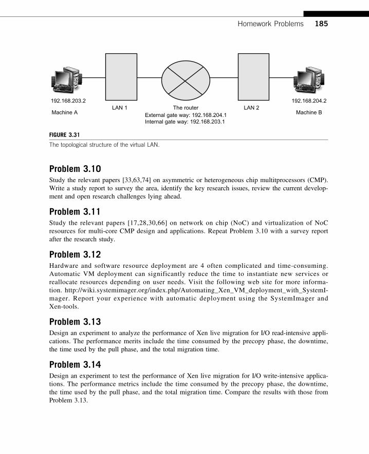
Problem 3.10Study the relevant papers [33,63,74] on asymmetric or heterogeneous chip multitprocessors (CMP).Write a study report to survey the area, identify the key research issues, review the current develop-ment and open research challenges lying ahead.
Problem 3.11Study the relevant papers [17,28,30,66] on network on chip (NoC) and virtualization of NoCresources for multi-core CMP design and applications. Repeat Problem 3.10 with a survey reportafter the research study.
Problem 3.12Hardware and software resource deployment are 4 often complicated and time-consuming.Automatic VM deployment can significantly reduce the time to instantiate new services orreallocate resources depending on user needs. Visit the following web site for more informa-tion. http://wiki.systemimager.org/index.php/Automating_Xen_VM_deployment_with_SystemI-mager. Report your experience with automatic deployment using the SystemImager andXen-tools.
Problem 3.13Design an experiment to analyze the performance of Xen live migration for I/O read-intensive appli-cations. The performance merits include the time consumed by the precopy phase, the downtime,the time used by the pull phase, and the total migration time.
Problem 3.14Design an experiment to test the performance of Xen live migration for I/O write-intensive applica-tions. The performance metrics include the time consumed by the precopy phase, the downtime,the time used by the pull phase, and the total migration time. Compare the results with those fromProblem 3.13.
192.168.203.2
Machine A
192.168.204.2
Machine BLAN 1
External gate way: 192.168.204.1Internal gate way: 192.168.203.1
LAN 2The router
FIGURE 3.31
The topological structure of the virtual LAN.
Homework Problems 185
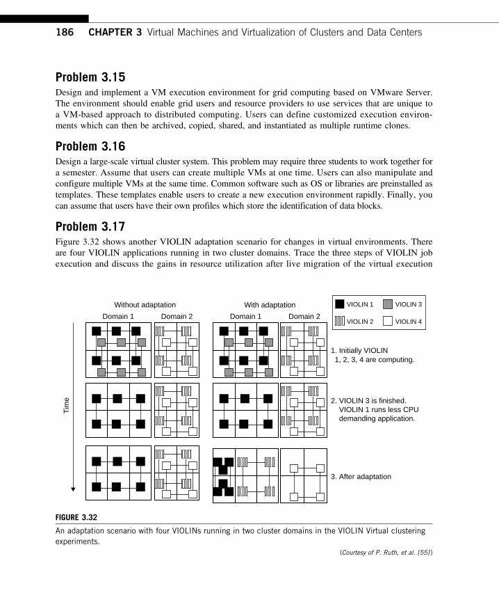
Problem 3.15Design and implement a VM execution environment for grid computing based on VMware Server.The environment should enable grid users and resource providers to use services that are unique toa VM-based approach to distributed computing. Users can define customized execution environ-ments which can then be archived, copied, shared, and instantiated as multiple runtime clones.
Problem 3.16Design a large-scale virtual cluster system. This problem may require three students to work together fora semester. Assume that users can create multiple VMs at one time. Users can also manipulate andconfigure multiple VMs at the same time. Common software such as OS or libraries are preinstalled astemplates. These templates enable users to create a new execution environment rapidly. Finally, youcan assume that users have their own profiles which store the identification of data blocks.
Problem 3.17Figure 3.32 shows another VIOLIN adaptation scenario for changes in virtual environments. Thereare four VIOLIN applications running in two cluster domains. Trace the three steps of VIOLIN jobexecution and discuss the gains in resource utilization after live migration of the virtual execution
Domain 1 Domain 2
Without adaptation
Tim
e
With adaptation
VIOLIN 2
VIOLIN 1
VIOLIN 4
VIOLIN 3
Domain 1 Domain 2
1, 2, 3, 4 are computing.1. Initially VIOLIN
2. VIOLIN 3 is finished. VIOLIN 1 runs less CPU demanding application.
3. After adaptation
FIGURE 3.32
An adaptation scenario with four VIOLINs running in two cluster domains in the VIOLIN Virtual clusteringexperiments.
(Courtesy of P. Ruth, et al. [55] )
186 CHAPTER 3 Virtual Machines and Virtualization of Clusters and Data Centers
environment in the two cluster domains. You can check your results against the cited paper tocompare your observations.
Problem 3.18After studying the material presented in Section 3.3.5, plus reading the papers by Wells, et al. [74]and by Marty and Hill in [39] answer the following two questions:
a. Distinguish virtual cores from physical cores and discuss the mapping technique in Wells’spaper on upgrading resource utilization and fault tolerance in using virtualized multicoreprocessors.
b. Study the cache coherence protocol presented in the Marty and Hill paper and discuss itsfeasibility and advantages to implement on many-core CMP in the future.
Homework Problems 187