Embed Size (px)
Citation preview

CHAPTER - VI WATER HARVESTING STRUCTURES PLANNING,
DESIGN AND CONSTRUCTION

39
CHAPTER - VI
WATER HARVESTING STRUCTURES PLANNING, DESIGN AND CONSTRUCTION
6.0 INTRODUCTION As mentioned in Chapter-V, there are many ways of harvesting water. All these methods basically fall under three main categories viz.: • Surface water collection • Ground water collection • Augmentation of ground water recharge The methods which are particularly useful in augmenting drinking water availability especially in the rural areas and which can be easily adopted at a moderate cost with the involvement of the local people are discussed in the following paras. 6.1 ROOF TOP HARVESTING Rain water may be harvested in areas, having rainfall of considerable intensity, spread over the larger part of the year e.g. the Himalayan areas, northeastern states, Andaman Nicobar, Lakshadweep islands and southern parts of Kerela and Tamil Nadu. This is an ideal solution of water problem where there is inadequate groundwater supply and surface sources are either lacking or insignificant. Rain water is bacteriologically pure, free from organic matter and soft in nature. In this system, only roof top is the catchment (see Figure 6.1, 6.2 and 6.3). The roofing should be of galvanized iron sheets (G.I.), aluminium, clay tiles, asbestos or concrete. In case of thatch-roof, it may be covered with waterproof LDPE sheeting. For collection of water, a drain is provided (Gutter) along the edge of the roof. It is fixed with a gentle slope towards down pipe, which is meant for free flow of water to the storage tank. This may be made up of G.I. sheet, wood, bamboo or any other locally available material. The down pipe should be at least 100 mm diameter and be provided with a 20 mesh wire screen at the inlet to prevent dry leaves and other debris from entering it. During the period of no rain, dust, bird droppings etc. accumulate on the roof. These are washed off with the first rains and enter the storage tank to contaminate the water. This can be prevented by two methods : (a) Simple diversion of foul water (b) Installation of foul flush system

40
Figure 6.1 : Typical Roof Top Harvesting Structure
Under method (a), the down pipe is moved away from the inlet of the storage tank initially during the rains, until clean water flows. Under method (b), storage provision for initial rain is kept in a pipe. These are cleaned off after each heavy rain. These are provided between down pipe and the storage tank. Filter materials such as sand, gravel or coconut/ palm/ betalnut fibre etc. are used as filter media. Storage tank can be constructed underground or above ground. The underground tank may be masonry or R.C.C. structure suitably lined with water proofing materials. The surface tank may be of G.I. sheet, R.C.C., Plastic/ HDP or Ferrocement Tank placed at a little higher elevation on a raised platform. To facilitate cleaning of the tank, an outlet pipe may be fitted and fixed in the tank at bottom level. The size of the tank will depend upon the factors such as daily demand, duration of dry spell, catchment area and rainfall. The tank is provided with : - a manhole of 0.50 m × 0.50 m size with cover - vent pipe/ over flow pipe (with screen) of 100 mm dia. - drain pipe (100 mm dia.) at bottom Choice of the tank depends on locally available materials and space available. When the tank is constructed underground, at least 30 cm of the tank should remain above ground. The withdrawal of water from the underground tank is made by installing hand pump on it. In case of surface tank, tap can be provided.

41
Before the tank is put into use it should be thoroughly cleaned and disinfected with high dosage of chlorine. Since the water shall remain stored for quite a long time, periodical disinfection of stored water is essential to prevent growth of pathogenic bacteria. Typical drawings of roof water harvesting structures are shown in Figure 6.1, 6.2 and 6.3.
Figure 6.2 : Roof Water Harvesting Scheme
Figure 6.3 : Roof Water Collection Structures

42
Water Availability Since the available roof area is usually limited, the system is used to meet water requirements during the summer months i.e. about 90 days. Water availability for a given roof top area and rainfall can be determined from Table A-1.1 of Appendix-I. Site Assessment Assessing the site conditions together with the future tank owners is the first step towards a sound system design. The five main site conditions to be assessed are : • availability of suitable roof catchment • foundation characteristics of soil near the house • location of trees • estimated runoff to be captured per unit area of the roof • availability and location of construction material Estimating the Size of the Required Systems In actual field conditions, the size of the collector and storage system is dictated by the available roof area and the rainfall. Both these factors are beyond our control except that some modifications can be made in the type of roof covering to improve runoff. The water harvested from the available roof area, therefore, is more or less fixed and has to be judiciously used. In rare cases we have the real option of building enough roof area to meet the predetermined per capita requirement of a given family or community. However, for the purpose of illustration, the planning and design procedure for such a system is discussed below : The size of the catchment area and tank should be enough to supply sufficient water for the users during the dry period. Assuming a full tank at the beginning of the dry season (and knowing the average length of the dry season and the average water use), the volume of the tank can be calculated by the following formula : V = (t × n × q) + et Where,
V = Volume of tank (litres) t = Length of the dry season (days) n = Number of people using the tank q = Consumption per capita per day (litres) et = Evaporation loss during the dry period
Since evaporation from a closed storage tank is negligible, the evaporation loss (et) can be ignored (=zero)

43
Design Example If, for example, 40 lpd (q) is agreed upon and a dry period of 80 days (t) is normally not exceeded, a storage volume of 16 m3 would be required for a family of 5 members (n). [V = 80 (t) × 5 (n) × 40 (q) = 16,000 litres or 16 m3] The required catchment area (i.e. the area of the roof) can be determined by dividing the volume of the tank by the accumulated average rainfall volume (in litres) per unit area (in m2) over the preceding wet months and multiplying this with the runoff coefficient, which can be set at 0.8 for galvanized iron or tiled roofs. Experience shows that with the water storage tanks next to their houses, people use between 20-40 litres of water per person per day (lpd). However, this may rise in time as people relax their water use habits because of easy access. This contrasts with a maximum of l0 lpd consumption levels under similar environments with people fetching water from distant sources. Together with the community/ family, a decision must be taken on how the water will be used or what affordable service level can be provided. General Design Features Rooftop water harvesting systems can provide good quality potable water if the design features outlined below are taken into account. • The substances that go into the making of the roof should be non-toxic in nature. • Roof surfaces should be smooth, hard and dense since they are easier to clean and are
less likely to be damaged and release materials/ fibres into the water. • Roof painting is not advisable since most paints contain toxic substances and may
peel off. • No overhanging trees should be left near the roof. • The nesting of birds on the roof should be prevented. • All gutter ends should be fitted with a wire mesh screen to keep out leaves, etc. • A first-flush rainfall capacity, such as detachable down pipe section, should be
installed. • A hygienic soak away channel should be built at water outlets and a screened
overflow pipe should be provided. • The storage tank should have a tight fitting roof that excludes light, a manhole cover
and a flushing pipe at the base of the tank (for standing tanks). • There should be a reliable sanitary extraction device such as a gravity tap or a hand
pump to avoid contamination of the water in the tank. • There should be no possibility of contaminated wastewater flowing into the tank
(especially for tanks installed at ground level). • Water from other sources, unless it is reliable source, should not be emptied into the
tank through pipe connections or the manhole cover.

44
Design of System Components By now, it is clear that a rooftop catchment system has three main components, viz. a roof, a guttering and first flush device and a storage tank. (a) Roof : The roof should be smooth, made of non-toxic substances and sufficiently
large to fill the tank with the available rainfall conditions. Existing roofs of houses and public buildings can be used for a rooftop catchment system. In some cases enlarged or additional roofed structures can be built.
(b) Guttering and first-flush device : Guttering is intended to protect the building by collecting the water running off the roof and direct it, via a down pipe, to the storage tank. Gutters should have a uniform slope of 0.5 percent large enough to collect the heavy runoff from high-intensity rain.
With all roof catchment tanks, the first rainwater running off the roof should be discarded. This helps keep the water potable because this first flush of rainwater contains large quantities of leaves and bird droppings. The importance of such first flush devices became clear from a study undertaken in Malaysia. The study showed how the faecal coliform count in runoff water was reduced from 4 to 60 per litre to zero, as the first five litres of runoff washed a roof measuring 15 m2.
(c) Tank : Water tanks using ferrocement technology come in different designs with volumes ranging between 2 and 200 m3. For example, a freestanding cylindrical tank can be built in sizes between 10 and 30 m3, while a capacity of upto 200 m3 is possible with sub-surface covered tanks. The latter is most economical when the capacity exceeds 50 m3. The principles of construction of ferrocement tanks involving the use of a corrugated iron moulds are widely adopted (see Figure A-2.1 of Appendix-II). An alternate design avoiding framework involves erecting a circular frame made of welded-mesh bars spaced at 15 cm and covered with chicked wire mesh (2.5 cm gauge) onto a reinforced concrete base. This is then covered on the outside with sacks or cloth and two coats of a 1.5 cm layer of mortar (1 part cement, 3 parts sand) plastered along the inner walls to produce the tank wall. Two further coats of plaster are added, one on the outside after removing the sacks and one on the inside to provide a tank wall thickness of 5 cm. A waterproof coat of just cement and water is then added to the tank’s inner wall. When the wall is complete, a wooden frame is constructed inside the tank to support the metal template made from old oil drums, which forms the mould for the domed roof. The roof is also reinforced with weld-mesh and chicken wire. For quality, the floor, walls and the roof need to be cured by moistening their surface for at least a week. This should start immediately after each component is ready. The Principles of Construction, Material and Design of Ferrocement Tank are explained in Appendix-II.

45
Management and Maintenance Roof top catchment tanks, like all water supply systems, demand periodic management and maintenance to ensure a reliable and high quality water supply. If the various components of the system are not regularly cleaned, water use is not properly managed, problems are not identified or necessary repairs not performed, the roof catchment system will cease to provide reliable, good quality supplies. On the following page is a rough timetable of maintenance and management requirements that gives a basis for monitoring checks. 1. During the rainy season, the whole system (roof catchment, gutters, pipes, screens,
first-flush and overflow) should be checked before and after each rain and preferably cleaned after every dry period exceeding a month.
2. At the end of the dry season and just before the first shower of rain is anticipated, the
storage tank should be scrubbed and flushed of all sediment and debris (the tank should be re-filled afterwards with a few centimetres of clean water to prevent cracking). Ensure timely service (before the first rains are due) of all tank features, including replacement of all worn screens and servicing of the outlet tap or hand pump.
Water Use Management Control over the quantity of water abstracted from the tank is important to optimise water use. Water use should be managed so that the supply is sufficient to last through the dry season. Failure to do so will mean exhausting all the stored water. In effect it will mean going back to where the user began, i.e. trekking long distances for poor quality water. On the other hand, underutilization of the water source due to severe rationing may leave the user dissatisfied with the level of the service provided. 6.2 TANKA/ KUND/ KUNDI Tanka is generally circular in shape and is constructed in stone masonry in 1:3 cement-sand mortar. While small Tankas of 3 to 4.22 m diameter and about 21-59 cum capacity are built by individual households, larger ones of 6 m diameter and 200 cum capacity are built for the village communities. In both these cases the depth is kept equal to the diameter. The catchment of the Tanka is treated in a variety of ways to increase the rain water collection. The commonly used materials are murrum, coal ash, gravel, pond silt, Bentonite, soil-cement mix, lime concrete, sodium carbonate etc. Because of the constraints of availability of large open areas around the Tanka and the unit cost of treatment, a circular strip of land of 12 m width around the Tanka is usually treated, the slope of which is kept as 3% i.e. a fall of 3 cm in a length of 1 m. This provides bulk of the requisite amount of water to fill the Tanka. Remaining water is received from the natural catchment outside the treated area. Reference Tables and Design Example for Tanka are given in Appendix-III.

46
Site Selection Tanka of about 21 cum capacity for an individual household should preferably be built in front of the house in an open area of about 10 m x 10 m size. Since the rainwater from this area is to be collected in the Tanka, the area should be such that human activity and cattle grazing may be prevented during the monsoon season to prevent pollution of water. For community Tanka of about 200 cum capacity the size of the open area should be at least 30 m × 30 m. In both the cases the land surface should be firm and sandy with gentle slope of about 3 % i.e. with a fall of 3 cm in 1 metre length. Site Preparation The selected area should be cleared of all vegetation i.e. grass, shrubs, bushes etc. A circle of 10 m diameter in case of the household tanka and 30 m diameter in case of community tanka should be drawn to mark the rain-water-collection area (catchment area). In case of the smaller Tanka the catchment area should be suitably dressed to provide an inward slope of 3 cm in 1 metre length towards the centre. For the community Tanka, the desired slope can be provided even in one direction i.e. in the general direction of the natural ground slope. In this case entry of rain water into the Tanka is ensured by building a semi-circular earthen bund at the lower end of the catchment area. Planning and Design Criteria 1. Water Requirement
A Tanka of 21 cum capacity is usually adequate to meet the minimum drinking water requirements of a family of 6 persons for one year. Community Tankas, however, have only a supplemental role since these can only partially meet the requirements depending upon the size of the community and the availability of land for constructing the Tankas. Viewed in this light, water requirement of the community is not necessarily a governing criterion for design of a Tanka scheme. Instead, conservation of available water and its proper distribution and use are of crucial importance. 2. Water Availability (a) Untreated Catchment Some part of the rainwater is lost due to evaporation and seepage into the ground. This loss varies with the amount of rainfall. For low rainfall the losses are high and for high rainfall these are low. Availability of rainwater for a Tanka from a natural catchment can be computed from the Table A-3.1 of Appendix-III.

47
(b) Treated Catchment Volume of rain water that can be collected from a treated catchment around the Tanka can be worked out from the Table A-3.2 of Appendix-III. 3. Structural Design For 21 cum capacity (see Figure 6.4) : (i) Foundation excavation: Area 3.9 m diameter and 3.5 m deep (ii) Foundation concrete: 1:3:6 CC 250 mm thick over an area of 3.9 m diameter (iii) Tanka Wall: 1:2:4 CC Wall 150 mm thick with 5 mm Cement Plaster (iv) Tanka Cover: Stone slab roof, at height of 1.0 m from G.L. (v) Apron around Tanka: 1:3:6 CC Apron, 1.0 m wide and 100 mm thick (vi) Deep Catch Pit at the bottom of Tanka: Size 1000 x 250 mm (vii) Slope of artificial/ treated catchment around Tanka: 3% to 4% - a fall of 3 cm in a
length of 1 m (viii) 3 Inlets and 1 Outlet in Tanka wall at apron level: Size 0.6 x 0.3 m with Iron Bars and
Expanded Metal (ix) Opening at the top (for drawing water): Size 1.0 x 1.0 m For 200 cum capacity (see Figure 6.5) : (i) Foundation excavation: Area 9.15 m diameter and 6.32 m deep (ii) Foundation concrete: 1:3:6 CC 230 mm thick over an area of 9.15 m diameter (iii) Tanka Wall: RR masonry 1.45 m thick at bottom in 1:3 cement-sand mortar gradually
reduced in steps to 0.38 m at the top (iv) Tanka Cover: Stone slabs over 3 Nos. R.S. Joists of size 0.20 x 0.15 m (v) Apron around Tanka: 1.6 m wide and 115 mm thick (vi) Deep Catch Pit at the bottom of Tanka: Size 915 x 230 mm (vii) Silt Collecting Gutter: Size 305 x 305 mm, bottom 75 mm thick 1:2:4 Lime Concrete
and 230 mm thick RR masonry, sides 230 mm thick RR masonry (viii) Slope of treated catchment around Tanka: 3% to 4% - a fall of 3 cm in a length of 1 m (ix) 3 Inlets and 1 Outlet in Tanka wall at apron level: Size 0.6 x 0.3 m with Iron Bars (x) Opening at the top (for drawing water): Size 0.9 x 0.9 m
Note: (i) For rain water yield from natural catchment outside the treated area refer Table A-3.1
of Appendix-III. (ii) Catchment should be treated for increasing rain water collection into the Tanka. (iii) For catchment treatment refer Table A-3.2 of Appendix-III. 4. Data Requirement (a) Secondary data • Monthly rainfall for about 10 years (Source: District Statistical Organisation) • Percentage of utilizable rainfall i.e. Runoff coefficient (Source: State Water Resources
Organisation or Central Water Commission)


50
(b) Primary data/ information • Land surface characteristics
- Should be gently sloping or flat - Sandy and firm - Moderate absorption of water - Easy to excavate upto about 6.5 m depth for Community Tanka
and 3.5 m depth for household Tanka • Availability of material for catchment treatment (Refer Table A-3.2 of Appendix-III
for choice of treatment) Advantages (i) Since the rainwater flows over gently sloping (3 to 4 % slope) sandy terrain, very little
sediment flows into the storage tank. However, the sediment comprising only sand particles quickly settles down at the bottom of the tank and therefore clear and clean water is available for drinking. With the tank fully covered at the top, the evaporation losses are negligible.
(ii) This method of rainwater harvesting being cheap, environment-friendly and effective, can be used widely to solve the problem of drinking water scarcity.
Disadvantages (i) Requires constant vigil during the rainy season to prevent entry of cattle and human
activity with in the catchment area to prevent contamination of water. (ii) Requires pre-monsoon cleaning of the Tanka and the catchment. (iii) Special care is required to prevent entry of reptiles and small animals into the Tanka
through the inlets/ outlet and the opening at the top. Geo-climatic Requirements/ Constraints (i) Tanka/ Kund/ Kundi can be built in any climatic region where the land slopes are
gentle and the surface is sandy and/ or rocky with out any harmful salts/ minerals. (ii) These are not useful in areas with steep slopes and where land surface has clayey
soils. 6.3 PERCOLATION TANK Percolation tanks are artificially created surface water bodies, submerging a land area with adequate permeability to facilitate sufficient percolation of impounded surface runoff to recharge the ground water. These have come to be recognized as a dependable mode for ground water recharge in the hard rock terrain covering two-third of the country. The hard rock areas with limited to moderate water holding and water yielding capabilities often experience water scarce situations due to inadequate recharge, indiscriminate withdrawal of ground water and mismanagement. These are quite popular in the states of Maharashtra, Andhra Pradesh, Madhya Pradesh, Tamil Nadu, Karnataka and Gujarat. The percolation tank is more or less similar to check dams or nala bund with a fairly large storage reservoir. A tank can be located either across small streams by creating low elevation check dams or in

51
uncultivated land adjoining streams, through excavation and providing a delivery canal connecting the tanks and the stream. General Guidelines (i) Percolation tanks should normally be constructed in a terrain with highly fractured
and weathered rock for speedy recharge. In case of alluvium, the bouldary formations are ideal. However, the permeability should not be too high that may result in the percolated water escaping in the downstream as regenerated surface flow.
(ii) The aquifer to be recharged should have sufficient thickness of permeable Vadose zone to accommodate recharge. The Vadose zone should normally be about 3 m below the ground level to minimize the possibility of water logging.
(iii) The benefited area should have sufficient number of wells, hand pumps etc. A minimum well density of 3 to 5 per square kilometres is desirable. The aquifer zone should extend upto the benefited area.
(iv) Submergence area should be uncultivated as far as possible. (v) The nature of the catchment is to be evaluated based on Strange’s Table for
classification under Good, Average and Bad Category. It is advisable to have the percolation tank in a good/ average catchment.
(vi) Rainfall pattern based on long-term evaluation is to be studied so that the percolation tank gets filled up fully during monsoon (preferably more than once).
(vii) Soils in the catchment area should preferably be of light sandy type to avoid silting up of the tank bed.
(viii) The location of the tank should preferably be downstream of runoff zone or in the upper part of the transition zone, with a land slope gradient of 3 to 5%.
(ix) The yield of a catchment area is generally from 0.44 to 0.55 MCM/sq.km in a low catchment area. Accordingly, the catchment area for small tanks varies from 2.5 to 4 sq.km and for larger tanks from 5 to 8 sq.km.
(x) The size of percolation tank is governed more by the percolating capacity of the formation under submergence rather than the yield of the catchment. Therefore, depending on the percolation capacity, the tank is to be designed. Generally, a percolation tank is designed for a storage capacity of 2.25 to 5.65 MCM. As a general guide the design capacity should normally not be more than 50 percent of the total quantum of utilizable runoff from the catchment.
(xi) While designing, due care should be taken to keep the height of the ponded water column about 3 to 4.5 m above the bed level. It is desirable to exhaust the storage by February since evaporation losses become substantial from February onwards. It is preferable that in the downstream area, the water table is at a depth of 3 to 5 m below ground level during the post monsoon period, implying that the benefited area possesses a potential shallow aquifer.
(xii) Construction-wise there is not much difference between a percolation tank and a minor irrigation tank, except for providing outlets for surface irrigation and the depth of the cut-off trench. The cut-off trench is to be provided below the earthen bund with depth limited to one fourth of the height between bed level and full storage level.

52
Design Aspects The design of percolation tanks involves detailed consideration of the following aspects: (i) The catchment yield is to be calculated for long-term average annual rainfall, using
Strange’s Table. Table A-3.1 of Appendix-III gives the yield from 1 hectare of Catchment for different values of monsoon rainfall.
(ii) The design of the dam is to be done on the basis of (a) the topographical setting of the impounded area, to calculate the height and length of the dam wall, its gradient, width and the depth of the foundation, taking into account the nature of the underlying formation; (b) details of the cut-off trench, to reduce seepage losses; (c) height of stone pitching on the upstream slope to avoid erosion due to ripple action and on the down stream slope from rain by suitable turfing; (d) upstream and downstream slopes to be moderate so that shear stress is not induced in the foundation beyond a permissible limit; and (e) stability of the dam.
(iii) Percolation tanks are normally earthen dams with masonry structures only for the spillway. Construction materials consist of a mixture of soil, silt, loam, clay, sand, gravel, suitably mixed and laid in layers and properly compacted to achieve stability and water tightness. The dam is not to be over-tapped, by providing adequate length of waste weir and adequate free board.
(iv) A waste weir is provided to discharge surplus water when the full pond level is reached. Maximum permissible discharge from the catchment is to be calculated using the formula approved by the competent authority based on local conditions. In the absence of such a formula, Inglis, or Dicken’s formula may be used based on the observed or design discharge and catchment areas for local culverts under road or railway bridges. Once the discharge is known the length of the waste weir is decided depending on the maximum flood discharge and permissible flood depth the crest of waste weir.
(v) Finally, measures indicated for the protection of catchment areas of rock dams hold good in the case of percolation tanks also.
(vi) The percolation tanks in a watershed may not have enough catchment discharge though a high capacity tank is possible as per site conditions. In such situations stream from nearby watershed can be diverted with some additional cost and the tank can be made more efficient. Such an effort was made in Satpura Mountain front area at Nagadevi, Jalgaon district, Maharashtra. The existing capacity of the tank of 350 TMC was never utilized after its construction. This could however be filled by stream diversion from adjacent watershed.
The Design Example of Percolation Tank with Drawings is given in Appendix-IV. Experience So Far Evaluation studies carried out on the functioning of the percolation tanks in Maharashtra state have indicated that a properly located, designed and constructed percolation tank can have an efficiency ranging from 78 to 91% with respect to recharge of ground water, leaving the balance for seepage losses (from nil to 8%) and evaporation losses (upto 8%). If the tank is filled more than once during the monsoon, enhancing utilization upto 150% of the storage capacity, optimal efficiency of the percolation tank is ensured. Generally, the zone of the influence in the downstream side extends up to 1 km. There is a strong case for propagating percolation tanks as a tool for managing ground water in hard rock areas, since it serves the

53
dual purpose of water harvesting and ground water recharging. Percolation tanks put into actual practice the much talked about integrated development of surface and ground water for their conjunctive use. 6.4 CHECK DAMS/ CEMENT PLUG/ NALA BUNDS Check dams are constructed across small streams having gentle slope and are feasible both in hard rock as well as alluvial formations. The site selected for check dam should have sufficient thickness of permeable bed or weathered formation to facilitate recharge of stored water within short span of time. The water stored in these structures is mostly confined to stream course and the height is normally less than 2 m. These are designed based on stream width and excess water is allowed to flow over the wall. In order to avoid scouring from excess run off, water cushions are provided at downstream side. To harness the maximum run off in the stream, series of such check dams can be constructed to have recharge on regional scale. A series of small bunds or weirs are made across selected nala sections such that the flow of surface water in the stream channel is impeded and water is retained on pervious soil/ rock surface for longer body. Nala bunds are constructed across bigger streams of second order in areas having gentler slopes. A nala bund acts like a mini percolation tank. Site Characteristic and Design Guidelines For selecting a site for Check Dams/ Nala Bunds the following conditions may be observed. (i) The total catchment of the nala should normally be between 40 to 100 Hectares
though the local situations can be guiding factor in this. (ii) The rainfall in the catchment should be less than 1000 mm/annum. (iii) The width of nala bed should be atleast 5 meters and not exceed 15 metres and the
depth should not be less than 1 metre. (iv) The soil downstream of the bund should not be prone to water logging and should
have pH between 6.5 to 8. (v) The lands downstream of check dam/ bund should have irrigable land under well
irrigation (This is desirable but not an essential requirement). (vi) The Nala bunds should be preferable located in area where contour or graded bunding
of lands have been carried out. (vii) The rock strata exposed in the ponded area should be adequately permeable to cause
ground water recharge through ponded water. (viii) Nala bund is generally a small earthen dam with a cutoff core wall of brick work,
though masonry and concrete bunds/ plugs are now prevalent. (ix) For the foundation for core wall a trench is dug 0.6m wide in hard rock or 1.2 metres
in soft rock of impervious nature. A core brick cement wall is created 0.6 m wide to stand atleast 2.5 metres above nala bed and the remaining portion of trench is back filled on upstream side by impervious clay. The core wall is buttressed on both sides by a bund made up of local clays and on the upstream face, stone pitching is done.
(x) Normally the final dimensions of the Nala bund are : length 10 to 15 metres, height 2 to 3 metres and width 1 to 3 metres, generally constructed in a trapezoidal form. If the bedrock is highly fractured, cement grouting is done to make the foundation leakage free.

54
(xi) Dams should be built at sites that can produce a relatively high depth to surface area so as to minimise evaporation losses.
(xii) Rocky surfaces should not be fractured or cracked, which may cause the water to leak away to deeper zones or beneath the dam.
(xiii) Dam foundation must be of solid impermeable rock with no soil pockets or fracture lines.
(xiv) Convenient location for user groups. (xv) No soil erosion in the catchment area. (xvi) Dams should be sited along the edges of depressions or directly across the lower ends
of deep gullies into the rock. The check dams are also popular and feasible in Bhabar, Kandi and talus scree areas of Uttar Pradesh, Punjab and Maharashtra and have had substantial impact on augmentation of ground water. The Design Example of Check Dam with Drawings is given in Appendix-V. 6.5 POND/ TANK Size Size of a pond is usually dictated by the availability of adequate land in the vicinity of the village. In rare cases do we have the option to design and build a pond of a desired size to meet the water requirements of the community. Where we have such an option, the first step is to work out the water requirement for various needs. The next step is to determine the catchment area, above the pond site, from where the monsoon run off would be available to fill the pond. Thereafter the location, alignment and height of the earthen bund are decided, as also the location and size of the spillway to evacuate the surplus monsoon discharge. Water Requirement and Gross Storage Unless otherwise prescribed for an area, following general guidelines may be used to determine the water requirements of a village community and the gross storage capacity of the pond. a. Irrigation : Provide about 0.67 hectare metre of capacity for a hectare of irrigation. b. Animal Needs : Provide at the following rates: Beef Cattle : 54-68 litres/day Dairy Cows : 68 litres/day (drinking) Dairy Cows (drinking + barn needs) : 158 litres/day
Pigs : 18 litres/day Sheep : 9 litres/day c. Domestic Water Needs : 40 litres per head per day d. Fish Culture : Ensure about 1.85 m depth to provide proper temperature
environments. The storage capacity should be at least double the total water requirement to take care of evaporation and seepage losses. As a rough guide, 10 per extra storage may be provided for sediment deposition. For example if the total annual water requirement is 10,000 cum and pond will have only one filling, its gross capacity should be 22000 cum (2 x 10,000 + 10%).
55
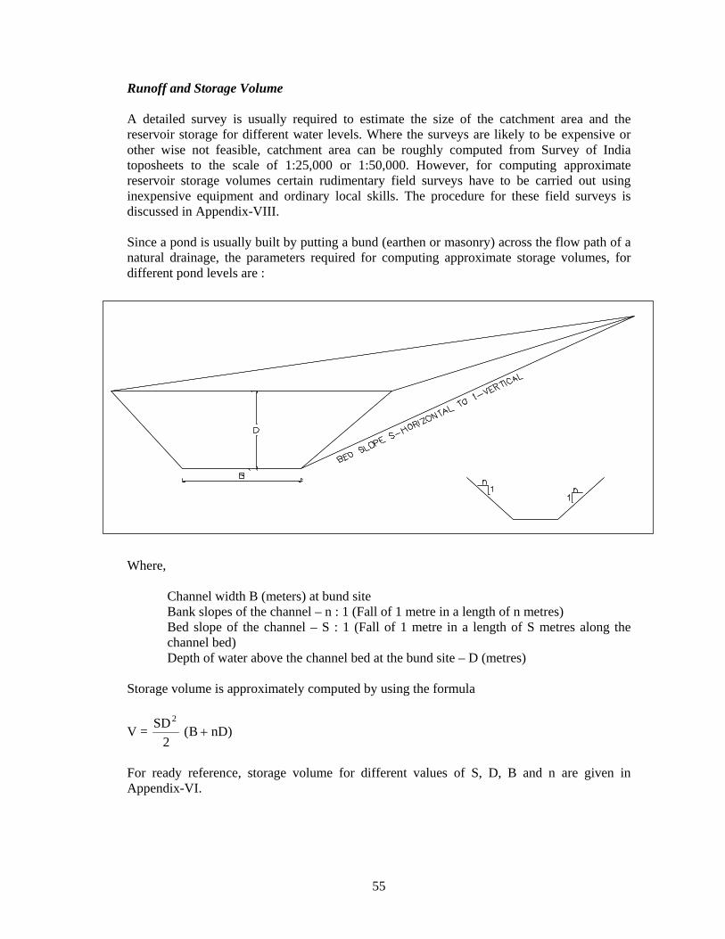
Runoff and Storage Volume A detailed survey is usually required to estimate the size of the catchment area and the reservoir storage for different water levels. Where the surveys are likely to be expensive or other wise not feasible, catchment area can be roughly computed from Survey of India toposheets to the scale of 1:25,000 or 1:50,000. However, for computing approximate reservoir storage volumes certain rudimentary field surveys have to be carried out using inexpensive equipment and ordinary local skills. The procedure for these field surveys is discussed in Appendix-VIII. Since a pond is usually built by putting a bund (earthen or masonry) across the flow path of a natural drainage, the parameters required for computing approximate storage volumes, for different pond levels are : Where,
Channel width B (meters) at bund site Bank slopes of the channel – n : 1 (Fall of 1 metre in a length of n metres) Bed slope of the channel – S : 1 (Fall of 1 metre in a length of S metres along the channel bed) Depth of water above the channel bed at the bund site – D (metres)
Storage volume is approximately computed by using the formula
V = 2
SD2)nDB( +
For ready reference, storage volume for different values of S, D, B and n are given in Appendix-VI.
56
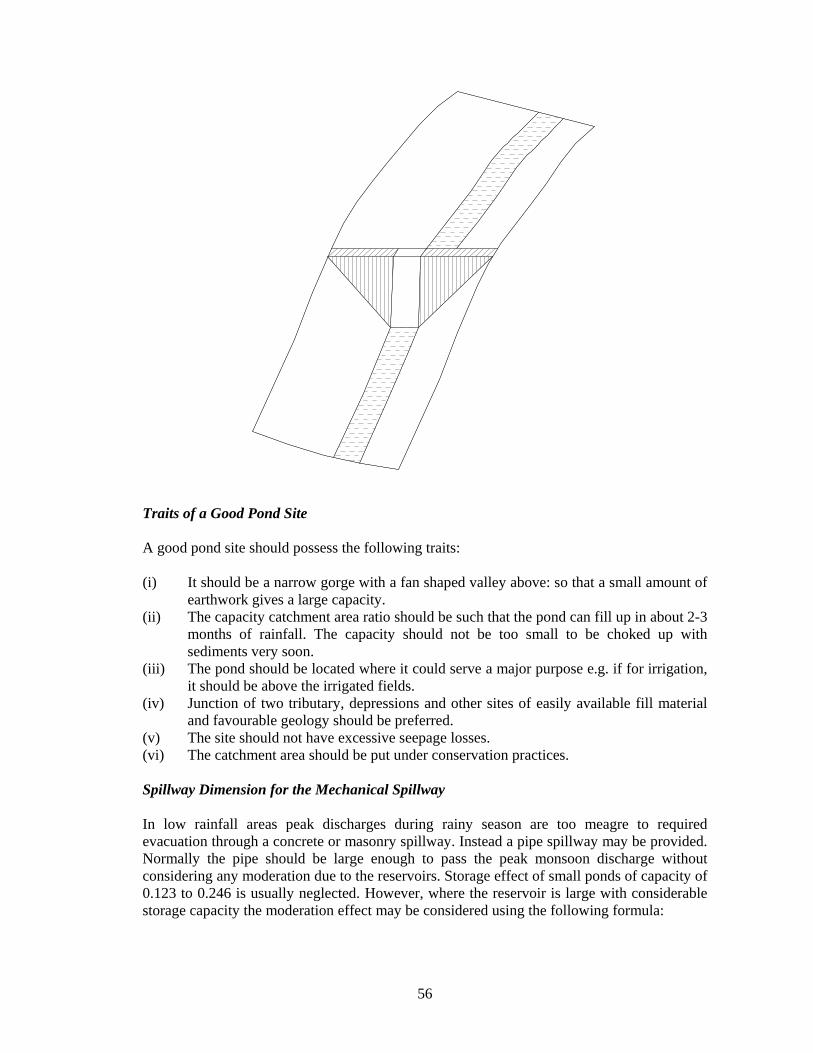
Traits of a Good Pond Site A good pond site should possess the following traits: (i) It should be a narrow gorge with a fan shaped valley above: so that a small amount of
earthwork gives a large capacity. (ii) The capacity catchment area ratio should be such that the pond can fill up in about 2-3
months of rainfall. The capacity should not be too small to be choked up with sediments very soon.
(iii) The pond should be located where it could serve a major purpose e.g. if for irrigation, it should be above the irrigated fields.
(iv) Junction of two tributary, depressions and other sites of easily available fill material and favourable geology should be preferred.
(v) The site should not have excessive seepage losses. (vi) The catchment area should be put under conservation practices. Spillway Dimension for the Mechanical Spillway In low rainfall areas peak discharges during rainy season are too meagre to required evacuation through a concrete or masonry spillway. Instead a pipe spillway may be provided. Normally the pipe should be large enough to pass the peak monsoon discharge without considering any moderation due to the reservoirs. Storage effect of small ponds of capacity of 0.123 to 0.246 is usually neglected. However, where the reservoir is large with considerable storage capacity the moderation effect may be considered using the following formula:

57
QQo = 1.25 − (
ARV1500
− 0.06)1/2
Where,
Qo = Rate of outflow when the pipe first flows full in cumecs Q = Peak rate of inflow in cumecs V = Available storage in ham R = Runoff in mm, and A = Drainage area in hectares (same as watershed area)
The above equation provides a rough guide to estimate of the size of the mechanical spillway pipe required. For ready reference Appendix-VII may be used to determine the diameter of the pipe for known values of Q, V, R and A. Structural Design The following general guidelines are kept in view for the structural design and construction of the pond: (i) Angle of repose is less for wet soil than for dry soils: so provide for flatter gradient on
the waterside of the earthfill. For very small ponds uniform slopes on both upstream and downstream sides can be provided (2½:1). For other provide a minimum slope of 3:1 on the waterside.
(ii) Remove all vegetation, roots, and organic matter from the fill area: scrape the upper 30 cm of the sol to get rid of the excessive roots: remove all tree stumps at the construction site (to come under the fill).
(iii) Provide a 1.5 m wide bottom key trench with 2:1 side slopes, to give a good bondage with the original earth.
(iv) Lay the earthwork in horizontal layers of not more than 8 centimetres at a time: water them to have a 14% moisture content: use sheep-foot roller for maximum compaction. Bulldozers fill earth in heaps, which cannot be easily completed. Use them for site clearance but not for earth fill.
(v) Place the conduit pipe of the mechanical spillway before starting the earthfill. (vi) Use topsoil and fertilisers to establish a quick grass cover on the earthfill. Do not let
trees or bushes come up on the embankment. (vii) At the inlet of the inflow runoff provide a measuring structure (triangular weir), drop
structure, or a sod chute so that when the pond is low, the inflow does not cause gullying. Cut all excavation on 2:1 or at least 1:1 side slopes.
(viii) The road on the crest should be provided with a gravel metal, middle camber and drains on sides (lead the road runoff safely down the slope in pipes or masonry/ concrete flumes or chutes. This can be otherwise a cause of gullying).
(ix) Provide for constant level livestock watering tank.

58
Selection of Site From an economic view point, the bund should be located where maximum storage volume is obtained for minimum volume of earthfill, since the major share of the cost goes into the earthfill. This condition, generally, can be met at a site where the stream/ or drainage channel is narrow, steep, side slopes are steep and stable, and the stream bed is of consolidated and nearly impervious formation. Such sites also minimise the pond area. Design of Earthen Bund The various components of an earthen bund include (a) foundation including key trench or cut-off, (b) height of bund, (c) side slopes, (d) top width, (e) free board and (f) settlement allowance. It is possible to construct a stable and economical earthen bund on any foundation. Sites with foundation conditions requiring relatively expansive construction measures should be avoided. The most satisfactory foundation is one that consists of, or is underlain at a shallow depth by a thick layer of relatively impervious consolidated material. Such foundations cause no stability problems. Where a suitable layer occurs at the surface no special measures are required. It is sufficient to remove the top soil (with vegetation and roots) and plough the area to provide a good bond with the new fill material of the bund. Where the impervious layer is overlain by pervious material (sand), a compacted clay cut-off extending from the surface of the ground into the impervious is required to prevent excessive seepage and to prevent possible failure by piping. Foundation Cutoffs Usually a cut-off joining the impervious stratum in the foundation with the base of the dam is needed. The most common type of cutoff is one constructed of compacted or puddled clay material. A trench, also called key-trench, is cut parallel to the central line of the bund to a depth that extends well into the impervious layer. The trench should have a bottom width of not less than 1.5 meters but adequate to allow the use of mechanical equipment if necessary, to obtain proper compaction. The sides of the trench should be filled with puddled clay or with successive thin layers of relatively impervious material each layer being properly compacted. Height of Bund The height of bund will depend upon the volume of runoff to be stored and topography of the reservoir area. The high of the bund should also be selected in such a way that its cost per unit of storage (cum volume) is minimum. While calculating the cost corresponding to any height some allowance for settlement and free board, and temporary flood storage may be added to give the actual bund height or in other words the actual quantity of earth work. Free Board It is the added height of the bund provided as a safety factor to prevent waves and flood runoff from over-topping the embankment.

59
(i) Minimum free board (F.B.) for length of pond upto 400 m 50 cm (ii) F.B. for length of pond upto 800 m 75 cm (iii) F.B. for length of pond more than 800 m 100 cm Settlement Allowance This includes the consolidation of the fill materials and the foundation materials due to the weight of the bund and increased moisture caused by the storage of water. Hand compacted (manually constructed) fill 10% of design height Machine compacted 5% of design height Top Width of Embankment Adequate top width is provided to the bund so that it can be used as road way and communication routes adjoining villages or watersheds. Simple formulae for top width (T.W.) as a function of height (H) may be used. Upto 10 m height, T.W. = H/5+2 10 to 15 m height, T.W. = H/5+3 Where,
H = Maximum height in m T.W. = Top width in m
Side Slope of Bund Adequate upstream and downstream side slopes of the embankment must be provided to satisfy the stability requirements of reservoir filled with water, sudden drawdown to minimise the erosion, and to facilitate establishment of good sod forming grass. The maximum side slopes recommended in case of small earth dams are given below in Table 6.1. Table 6.1 : Maximum Side Slopes recommended in case of Small Earth Dams
Side Slopes Depth of Fill
(Height) Upstream Downstream Upto 5 m 2:1 2:1 5 to 10 m (i) 2.5:1
(ii) 3.0:1 2:1 or 2.5:1 2.5:1
10 to 15 m 3:1 3:1 When fill material consists of more clay and silt, flatter slope of 3 : 1 on the upstream is always recommended. Steps in Construction i) Site clearing-striping vegetation, pervious top earth ii) Staking for the base and key trench iii) Key trench digging and filling
60
iv) Preparation of earth fill material with optimum moisture v) Placement and compaction of earth in layers vi) Provision and completion of irrigation outlet and spillway vii) Trimming slopes to correct angle viii) Protection of upstream and downstream slopes Maintenance A properly designed and constructed bund is well protected by sod and requires, least maintenance. Particular attention should be given to surface erosion, the development of seepage areas on the downstream face of below the top of the dam, evidence of piping, wave action and damage by cattle and human beings and corrective steps should be taken in time. 6.6 GABION STRUCTURE This is a kind of check dam being commonly constructed across small stream to conserve stream flows with practically no submergence beyond stream course. The boulders locally available are stored in a steel wire mesh and are tied up in the form of rectangular blocks (Figure 6.6). This is put up across the stream to make it as a small dam by anchoring it to the stream banks (Figure 6.6). The height of such structures is around 0.5 m and is normally used in the streams with width of about 10 to 15 m. The excess water overflows this structure storing some water to serve as source of recharge. The silt content of stream water in due course is deposited in the interstices of the boulders to make it more impermeable. These structures are common in Maharashtra, Madhya Pradesh, Andhra Pradesh etc. 6.7 GROUND WATER DAMS OR SUB-SURFACE DYKES OR UNDERGROUND
BANDHARAS (UGB) These are basically ground water conservation structures and are effective in providing sustainability to ground water structures by arresting sub-surface flow. A ground water dam is a sub-surface barrier across stream, which retards the natural ground water flow of the system, and stores water below ground surface to meet the demands during the period of need (Figure 6.7). The main purpose of ground water dam is to arrest the flow of ground water out of the sub-basin and increase the storage within the aquifer. By doing so the water levels in upstream part of ground water dam rises saturating the otherwise dry part of aquifer. The underground dam has following advantages: • Since the water is stored within the aquifer, submergence of land can be avoided and
land above reservoir can be utilized even after the construction of the dam. • No evaporation loss from the reservoir takes place. • No siltation in the reservoir takes place • The potential disaster like collapse of dams can be avoided. Such dykes are also useful across the perennial streams. Dykes of 30 cm thick brick-cement or stone cement, extending down to the compact bedrock, with mud or clay fillings in excavated portions on both sides of the wall provide a perfect impermeable barrier.

61
Figure 6.6 : Gabion Structure
Figure 6.7 : Artificial Recharge through Underground Bandhara

62
Management and Maintenance The quality of water in groundwater dams is generally better than water from other water harvesting systems since water here is stored in the ground and filtered as it moves through the sandy soil. However, the shallow groundwater risks contamination from seepage of surface pollutants. Once the clay wall groundwater dam is built, it demands very little maintenance. However, the user community should check the dam site for erosion after each large flood. Any erosion should be corrected by refinishing the clay wall and protecting it with large rocks, which cannot be moved by smaller flows. With masonry groundwater dams, any channel erosion that might undermine or expose the dam should be arrested by filling it with large boulders and using silting traps to catch sandy material. It is a similar prescription for raised dams. With the raised dam, the gravity pipe should be checked frequently along its length for signs of damage or leaks and the tapping station should be kept in good order. Also with groundwater dams there may be a need to control water use, thus requiring supervision, clear agreements among the users and monitoring of the available storage. For the latter, a piezometer may be installed, which allows a caretaker or watchman to estimate how much water is left and if rationing has to be made more strict. The precautions to manage and maintain water quality and reliability in sub-surface and sand dams and to reduce the risk of contamination are: • Ensure there is no open defecation in/ near the river bed upstream • No tethering of donkeys at the well • Check bathing/ laundry upstream of the dam • There must be no pit-latrines on the bank upstream • There must be no unprotected wells in the river bed near the protected well • Regular maintenance of the protected well-site and the hand pump must be assured • Ensure use and maintenance of a downstream gravity out-take • Avoid use of pesticides/ chemicals upstream of the dam site 6.8 NADIS Nadis are small excavated or embanked village ponds, for harvesting meagre precipitation, to mitigate the scarcity of drinking water in the Indian desert. Water from these is available for periods starting two months to a year after rain, depending on the catchment characteristics, the amount of rainfall received and its intensity. This is an ancient practice and the Nadis are the most important water sources of the region. The first recorded masonry Nadi was constructed in 1520 A.D. near Jodhpur during the regime of Rao Jodhaji. Since Nadis are the vital water sources in the Indian arid zone, each village has one or more of these, depending on the water demand and availability sites. Location and size of a Nadi depends on the catchment area it commands. It should be located in areas with lowest elevation to have the benefit of natural drainage and need for minimum excavation of earth. Surface of catchment area should preferably be impermeable. If necessary, the catchment area may be prepared artificially by soil condition wherever possible. Silt Trap should be provided at the inlet point to prevent sediment load form entering the Nadi. The size of the silt trap should be designed keeping in view the site

63
conditions, duration and intensity of rainfall. Silt Trap should be cleaned regularly. The inlet should be stone pitched to prevent soil erosion. A mesh should be provided at the inlet to prevent floating material from entering the Nadi. The slope of the sides shall depend on the soil condition. In order to prevent seepage losses through sides and bottom, these are lined with LDPE sheeting. This should be embedded properly. The outlet should be stone-pitched to prevent soil erosion. An exploitation well should be constructed at a suitable point of Nadi to facilitate withdrawal of water. The well has to be constructed by raising two masonry wing walls and one front wall. A suitable platform fitted with iron fixtures for Pulley and Hand Pumps is necessary.
Table 6.2 : Effect of Rainfall on Nadi Volume/ Catchment Area Ratio
under different Physiographic Settings
Nadi Volume m3 per ha of Catchment Area for Various Rainfall Figures
Physiographic Setting
250-300 300-350 350-400 400-450 450-500 Dune Complex 55.3 110.5 53.0 37.1 - Sandy plain 120.4 128.0 131.1 137.3 - Younger alluvial plain
- - - 349.9 1066.9
Rocky/ gravel pediment
491.7 518.9 785.5 1644.7 2264.7
The traditional Nadis are affected by heavy sedimentation, high evaporation and seepage losses and water pollution. The highest Nadi volumes per unit of catchment areas were observed on dunes and sandy plain area with slopes of 1-2% (Table 6.3). In younger alluvial plains, rocky/ gravel pediments, Nadi volumes per unit of catchment area, increase with increasing slope. Similarly, the Nadi volumes per unit of catchment are under different rainfall zones are given in Table 6.2. In dune complexes, the Nadi volumes were highest in the 300-350 mm rainfall areas because of stabilisation of the sands with grass. Nadi usually have large surface areas compared to the volume of water stored and heavy losses occur since evaporation is a function of surface area. On the other hand, seepage increases with the depth of the stored water. LDPE lining was found to be useful in avoiding seepage losses (Figure 6.8).
Table 6.3 : Effect of Ground Slope on Nadi Volume/ Catchment Area Ratio under different Physiographic Settings
Physiographic Setting Nadi Volume m3 per ha of Catchment Area in
Different Slope Groups (%) <-1 1-2 2-3 3-4 4-5 >-5 Dune complex 54.3 108.2 45.7 29.0 - 13.8 Sandy plain 110.6 154.2 121.1 - - - Younger alluvial plain 466.4 578.5 731.8 - - - Rocky/ gravel pediment 51.4 421.5 724.7 945.9 - 1236.5

64
Figure 6.8 : Improved Design of Nadi – LDPE Lining
Due to poor maintenance and improper utilisation, the Nadi water is highly polluted and is not free from health hazards. Guinea worm, water hyacinth, mosses, algae are invariably present in large quantities. Infectious diseases like guinea worm are associated with the village where nadi water has been in use.

65
6.9 KHADIN The system is site specific needing a large natural, high runoff potential catchment in proximity of plain valley land. The ratio of Khadin area to catchment area, depending on type of catchment, is minimum i.e. 1:12 to 15. Since a decade, irrigation department of State has started making many new Khadins at various locations. Under Desert Development Programme also new Khadins are being constructed. Figure 6.9 shows plan and section of a typical Khadin. However, these need proper management. Before starting the construction of Khadin, bund position is aligned and then about 15 cm layer of natural ground surface is scrapped out. The earth work is done in layers of 30 cm thickness and then compacted by ramming with hand hammer, sheep foot roller or road roller. For providing shape to the bund, a profile at every 20 m length of bund is erected. Provision is made for over flow by providing cement-concrete spill-over structure with stone pitching, downstream to check erosion. Pipe outlet is also provided at centre of bund to drain out standing water. After completion of Khadin, levelling of land near bund is done for uniform spreading of water. Seeding of grass on bund during rainy season is done for its stabilisation. In big Khadins, making small dug wells outside Khadin bund is an innovative method developed by ancient people to have conjunctive use of water as also to encourage seeping out of saline water to prevent salinity development in Khadin in course of time. Following improvements in construction of Khadin are suggested: (i) Khadin is basically a runoff agricultural system. Though site specific, with good
management it can make arid wasteland productive. Modern experience is however limited to few isolated projects. Intensive techno-economic evaluation in several regions with different climates, soils and crops are needed to identify its potential for the future.
(ii) To make runoff agriculture more effective, there is a need to develop crops better suited to this system.
(iii) Though it is primary runoff agriculture, a lot of water gets stored on the land, partly going down deep, side ways and much is lost through evaporation. For conservation and conjunctive use of such collected water, research work on models of suppression of evaporation losses, is needed. The inability of dug wells around Khadins for drinking water supplies can be explored.

66
Figure 6.9 : Khadin System