Embed Size (px)
Citation preview
VECTOR MECHANICS FOR ENGINEERS:
STATICS
Eighth Edition
Ferdinand P. BeerE. Russell Johnston, Jr.
Lecture Notes:J. Walt OlerTexas Tech University
CHAPTER
© 2007 The McGraw-Hill Companies, Inc. All rights reserved.
Statics of Particles
© 2007 The McGraw-Hill Companies, Inc. All rights reserved.
Vector Mechanics for Engineers: Statics
EighthEdition
2 - 2
Contents
IntroductionResultant of Two ForcesVectorsAddition of VectorsResultant of Several Concurrent
ForcesSample Problem 2.1Sample Problem 2.2Rectangular Components of a Force:
Unit VectorsAddition of Forces by Summing
Components
Sample Problem 2.3Equilibrium of a ParticleFree-Body DiagramsSample Problem 2.4Sample Problem 2.6Rectangular Components in SpaceSample Problem 2.7
© 2007 The McGraw-Hill Companies, Inc. All rights reserved.
Vector Mechanics for Engineers: Statics
EighthEdition
2 - 3
Introduction
• The objective for the current chapter is to investigate the effects of forces on particles:
- replacing multiple forces acting on a particle with a single equivalent or resultant force,
- relations between forces acting on a particle that is in a state of equilibrium.
• The focus on particles does not imply a restriction to miniscule bodies. Rather, the study is restricted to analyses in which the size and shape of the bodies is not significant so that all forces may be assumed to be applied at a single point.
© 2007 The McGraw-Hill Companies, Inc. All rights reserved.
Vector Mechanics for Engineers: Statics
EighthEdition
2 - 4
Resultant of Two Forces
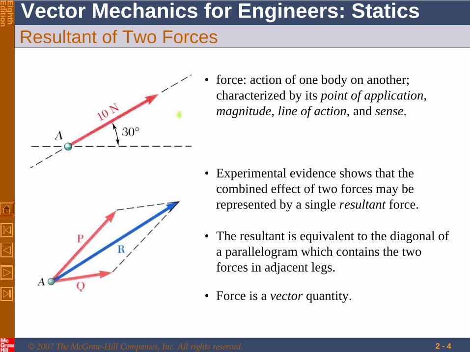
• force: action of one body on another; characterized by its point of application, magnitude, line of action, and sense.
• Experimental evidence shows that the combined effect of two forces may be represented by a single resultant force.
• The resultant is equivalent to the diagonal of a parallelogram which contains the two forces in adjacent legs.
• Force is a vector quantity.
© 2007 The McGraw-Hill Companies, Inc. All rights reserved.
Vector Mechanics for Engineers: Statics
EighthEdition
2 - 5
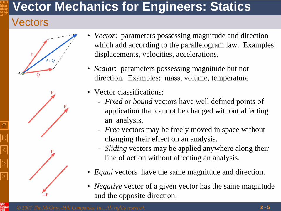
Vectors• Vector: parameters possessing magnitude and direction
which add according to the parallelogram law. Examples: displacements, velocities, accelerations.
• Vector classifications:- Fixed or bound vectors have well defined points of
application that cannot be changed without affecting an analysis.
- Free vectors may be freely moved in space without changing their effect on an analysis.
- Sliding vectors may be applied anywhere along their line of action without affecting an analysis.
• Equal vectors have the same magnitude and direction.
• Negative vector of a given vector has the same magnitude and the opposite direction.
• Scalar: parameters possessing magnitude but not direction. Examples: mass, volume, temperature
© 2007 The McGraw-Hill Companies, Inc. All rights reserved.
Vector Mechanics for Engineers: Statics
EighthEdition
2 - 6
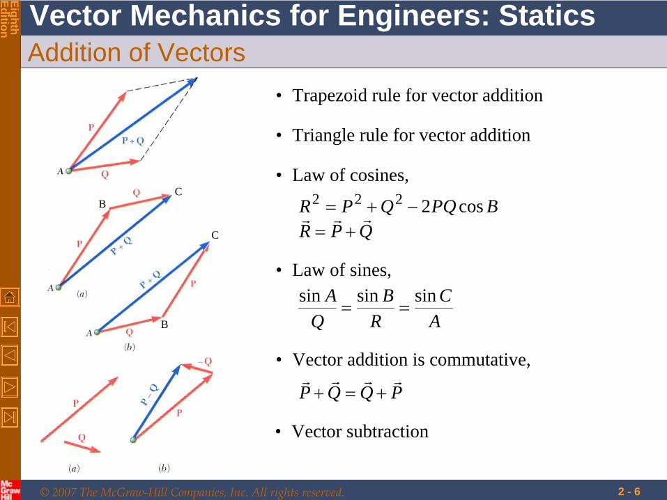
Addition of Vectors• Trapezoid rule for vector addition
• Triangle rule for vector addition
B
B
C
C
QPRBPQQPR
cos2222• Law of cosines,
• Law of sines,
AC
RB
QA sinsinsin
• Vector addition is commutative,
PQQP
• Vector subtraction
© 2007 The McGraw-Hill Companies, Inc. All rights reserved.
Vector Mechanics for Engineers: Statics
EighthEdition
2 - 7
Addition of Vectors
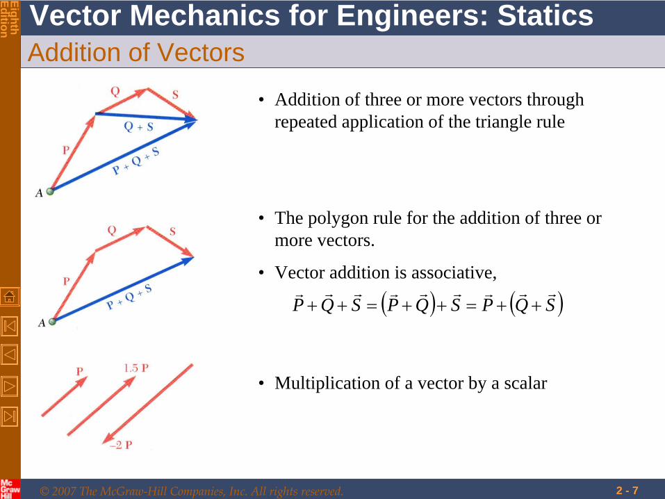
• Addition of three or more vectors through repeated application of the triangle rule
• The polygon rule for the addition of three or more vectors.
• Vector addition is associative,
SQPSQPSQP
• Multiplication of a vector by a scalar
© 2007 The McGraw-Hill Companies, Inc. All rights reserved.
Vector Mechanics for Engineers: Statics
EighthEdition
2 - 8
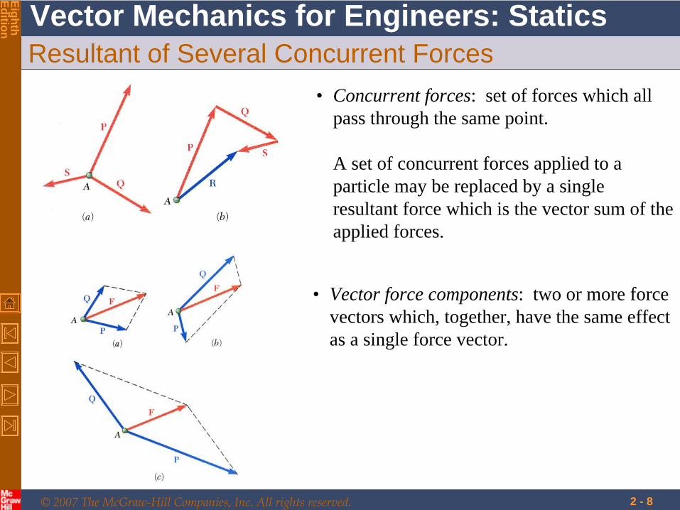
Resultant of Several Concurrent Forces• Concurrent forces: set of forces which all
pass through the same point.
A set of concurrent forces applied to a particle may be replaced by a single resultant force which is the vector sum of the applied forces.
• Vector force components: two or more force vectors which, together, have the same effect as a single force vector.
© 2007 The McGraw-Hill Companies, Inc. All rights reserved.
Vector Mechanics for Engineers: Statics
EighthEdition
2 - 9
Sample Problem 2.1
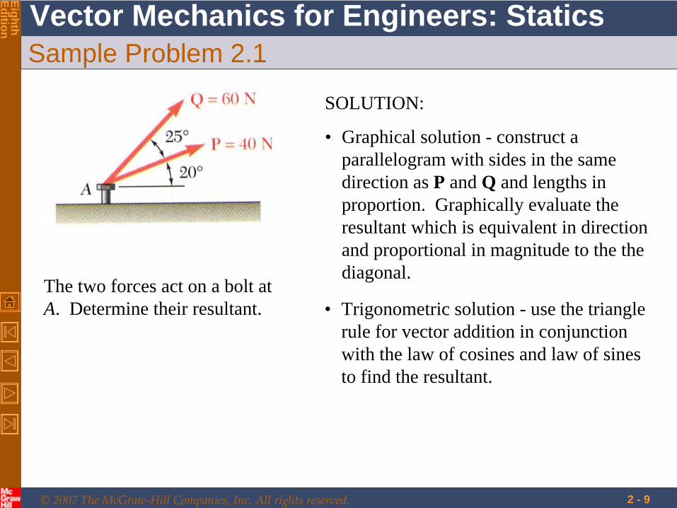
The two forces act on a bolt at A. Determine their resultant.
SOLUTION:
• Graphical solution - construct a parallelogram with sides in the same direction as P and Q and lengths in proportion. Graphically evaluate the resultant which is equivalent in direction and proportional in magnitude to the the diagonal.
• Trigonometric solution - use the triangle rule for vector addition in conjunction with the law of cosines and law of sines to find the resultant.
© 2007 The McGraw-Hill Companies, Inc. All rights reserved.
Vector Mechanics for Engineers: Statics
EighthEdition
2 - 10
Sample Problem 2.1
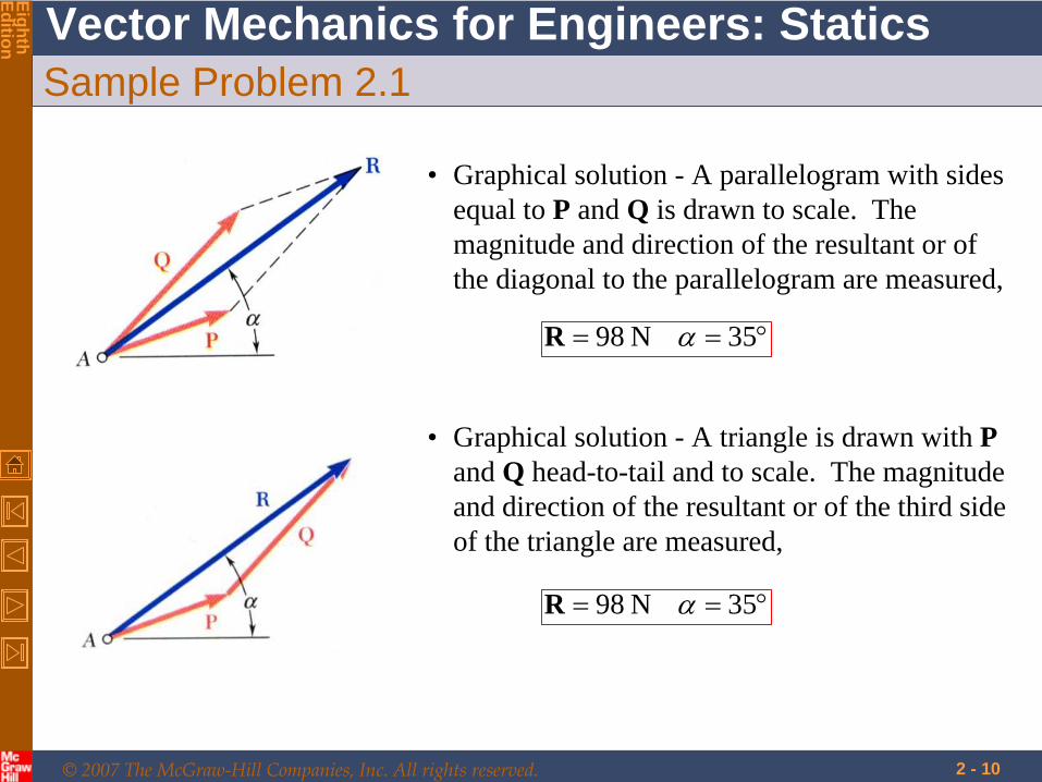
• Graphical solution - A parallelogram with sides equal to P and Q is drawn to scale. The magnitude and direction of the resultant or of the diagonal to the parallelogram are measured,
35N 98 R
• Graphical solution - A triangle is drawn with P and Q head-to-tail and to scale. The magnitude and direction of the resultant or of the third side of the triangle are measured,
35N 98 R
© 2007 The McGraw-Hill Companies, Inc. All rights reserved.
Vector Mechanics for Engineers: Statics
EighthEdition
2 - 11
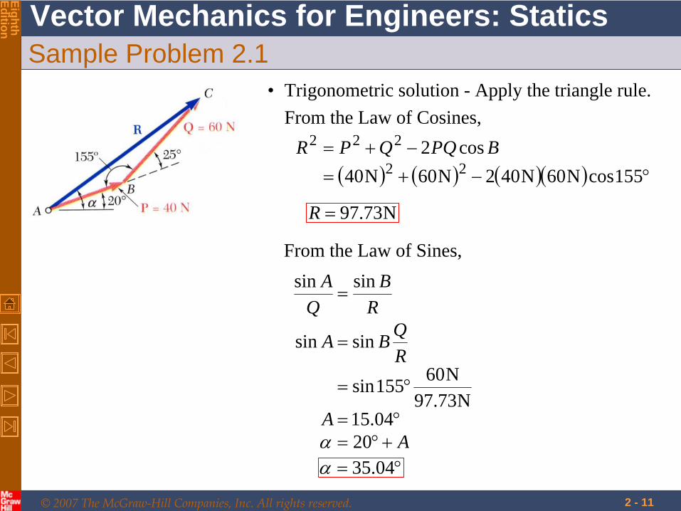
Sample Problem 2.1• Trigonometric solution - Apply the triangle rule.
From the Law of Cosines,
155cosN60N402N60N40cos222
222 BPQQPR
AA
RQBA
RB
QA
2004.15
N73.97N60155sin
sinsin
sinsin
N73.97R
From the Law of Sines,
04.35

© 2007 The McGraw-Hill Companies, Inc. All rights reserved.
Vector Mechanics for Engineers: Statics
EighthEdition
2 - 12
Sample Problem 2.2
a) the tension in each of the ropes for
= 45o,
b) the value of
for which the tension in rope 2 is a minimum.
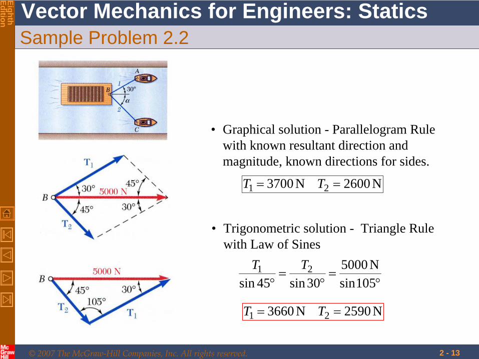
A barge is pulled by two tugboats. If the resultant of the forces exerted by the tugboats is 5000 N directed along the axis of the barge, determine
SOLUTION:• Find a graphical solution by applying the
Parallelogram Rule for vector addition. The parallelogram has sides in the directions of the two ropes and a diagonal in the direction of the barge axis and length proportional to 5000 N.
• The angle for minimum tension in rope 2 is determined by applying the Triangle Rule and observing the effect of variations in .
• Find a trigonometric solution by applying the Triangle Rule for vector addition. With the magnitude and direction of the resultant known and the directions of the other two sides parallel to the ropes given, apply the Law of Sines to find the rope tensions.
© 2007 The McGraw-Hill Companies, Inc. All rights reserved.
Vector Mechanics for Engineers: Statics
EighthEdition
2 - 13
Sample Problem 2.2
• Graphical solution - Parallelogram Rule with known resultant direction and magnitude, known directions for sides.
N2600N3700 21 TT
• Trigonometric solution - Triangle Rule with Law of Sines
105sinN5000
30sin45sin21 TT
N2590N3660 21 TT
© 2007 The McGraw-Hill Companies, Inc. All rights reserved.
Vector Mechanics for Engineers: Statics
EighthEdition
2 - 14
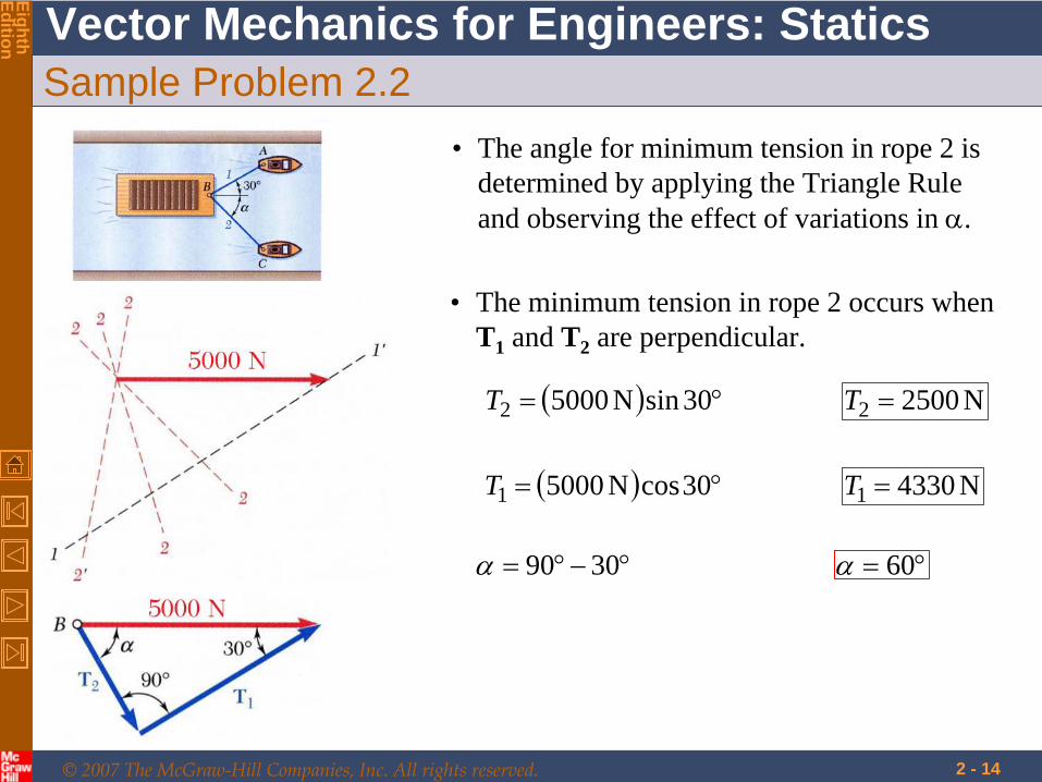
Sample Problem 2.2• The angle for minimum tension in rope 2 is
determined by applying the Triangle Rule and observing the effect of variations in .
• The minimum tension in rope 2 occurs when T1 and T2 are perpendicular.
30sinN50002T N25002 T
30cosN50001T N43301 T
3090 60
© 2007 The McGraw-Hill Companies, Inc. All rights reserved.
Vector Mechanics for Engineers: Statics
EighthEdition
2 - 15
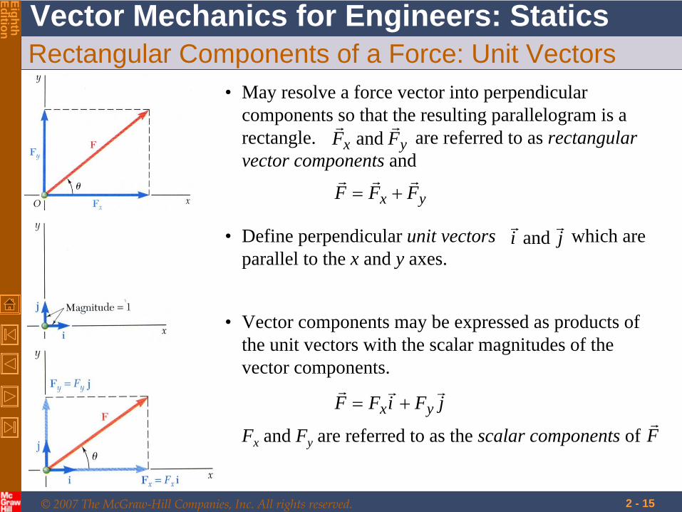
Rectangular Components of a Force: Unit Vectors
• Vector components may be expressed as products of the unit vectors with the scalar magnitudes of the vector components.
Fx and Fy are referred to as the scalar components of
jFiFF yx
F
• May resolve a force vector into perpendicular components so that the resulting parallelogram is a rectangle. are referred to as rectangular vector components and
yx FFF
yx FF
and
• Define perpendicular unit vectors which are parallel to the x and y axes.
ji
and

© 2007 The McGraw-Hill Companies, Inc. All rights reserved.
Vector Mechanics for Engineers: Statics
EighthEdition
2 - 16
Addition of Forces by Summing Components
SQPR
• Wish to find the resultant of 3 or more concurrent forces,
jSQPiSQPjSiSjQiQjPiPjRiR
yyyxxx
yxyxyxyx
• Resolve each force into rectangular components
xxxxx
FSQPR
• The scalar components of the resultant are equal to the sum of the corresponding scalar components of the given forces.
y
yyyyF
SQPR
x
yyx R
RRRR 122 tan
• To find the resultant magnitude and direction,
© 2007 The McGraw-Hill Companies, Inc. All rights reserved.
Vector Mechanics for Engineers: Statics
EighthEdition
2 - 17
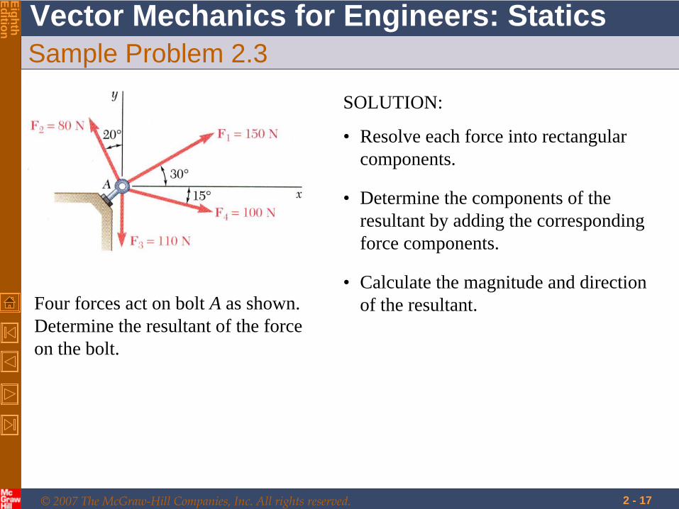
Sample Problem 2.3
Four forces act on bolt A as shown. Determine the resultant of the force on the bolt.
SOLUTION:
• Resolve each force into rectangular components.
• Calculate the magnitude and direction of the resultant.
• Determine the components of the resultant by adding the corresponding force components.
© 2007 The McGraw-Hill Companies, Inc. All rights reserved.
Vector Mechanics for Engineers: Statics
EighthEdition
2 - 18
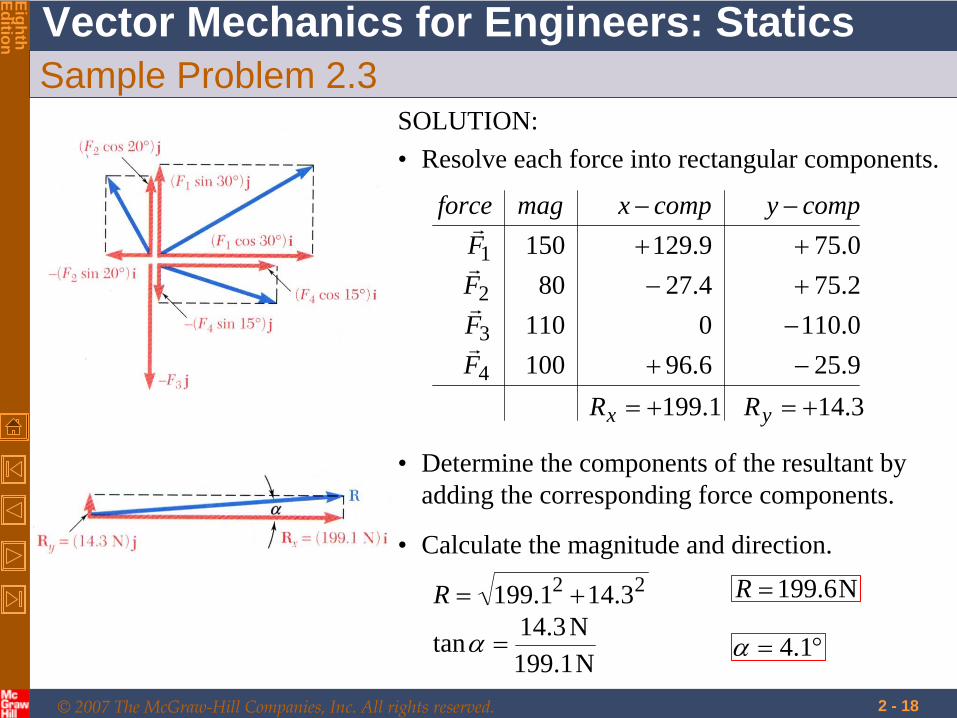
Sample Problem 2.3SOLUTION:• Resolve each force into rectangular components.
9.256.961000.11001102.754.27800.759.129150
4
3
2
1
FFFF
compycompxmagforce
22 3.141.199 R N6.199R
• Calculate the magnitude and direction.
N1.199N3.14tan 1.4
• Determine the components of the resultant by adding the corresponding force components.
1.199xR 3.14yR
© 2007 The McGraw-Hill Companies, Inc. All rights reserved.
Vector Mechanics for Engineers: Statics
EighthEdition
2 - 19
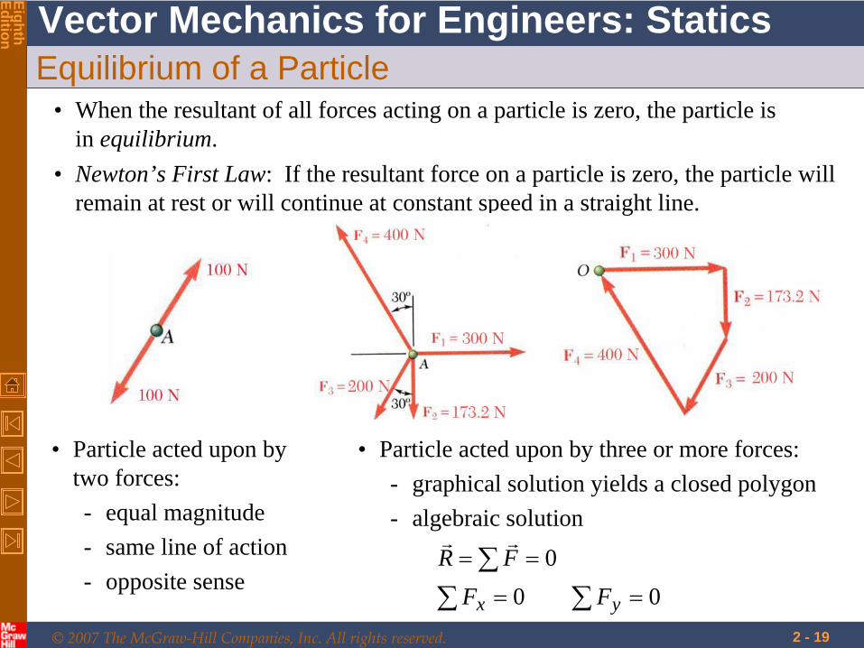
Equilibrium of a Particle• When the resultant of all forces acting on a particle is zero, the particle is
in equilibrium.
• Particle acted upon by two forces:- equal magnitude- same line of action- opposite sense
• Particle acted upon by three or more forces:- graphical solution yields a closed polygon- algebraic solution
000
yx FFFR
• Newton’s First Law: If the resultant force on a particle is zero, the particle will remain at rest or will continue at constant speed in a straight line.
© 2007 The McGraw-Hill Companies, Inc. All rights reserved.
Vector Mechanics for Engineers: Statics
EighthEdition
2 - 20
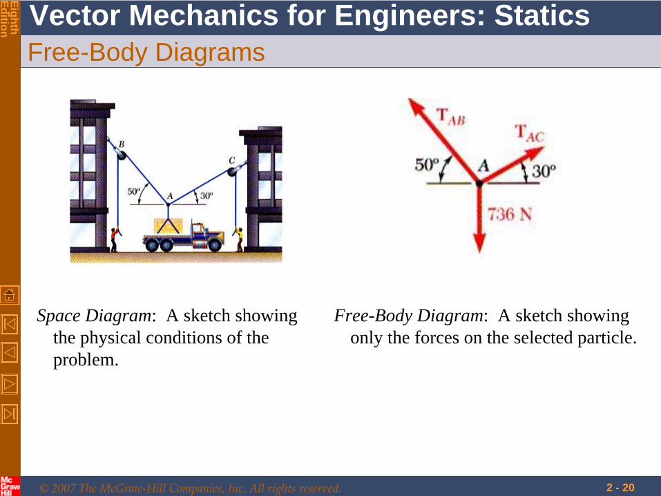
Free-Body Diagrams
Space Diagram: A sketch showing the physical conditions of the problem.
Free-Body Diagram: A sketch showing only the forces on the selected particle.
© 2007 The McGraw-Hill Companies, Inc. All rights reserved.
Vector Mechanics for Engineers: Statics
EighthEdition
2 - 21
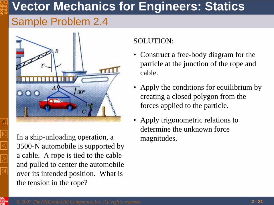
Sample Problem 2.4
In a ship-unloading operation, a 3500-N automobile is supported by a cable. A rope is tied to the cable and pulled to center the automobile over its intended position. What is the tension in the rope?
SOLUTION:
• Construct a free-body diagram for the particle at the junction of the rope and cable.
• Apply the conditions for equilibrium by creating a closed polygon from the forces applied to the particle.
• Apply trigonometric relations to determine the unknown force magnitudes.
© 2007 The McGraw-Hill Companies, Inc. All rights reserved.
Vector Mechanics for Engineers: Statics
EighthEdition
2 - 22
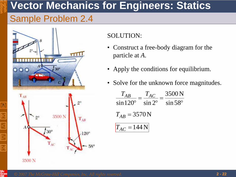
Sample Problem 2.4
SOLUTION:
• Construct a free-body diagram for the particle at A.
• Apply the conditions for equilibrium.
• Solve for the unknown force magnitudes.
58sinN3500
2sin120sinACAB TT
N3570ABT
N144ACT
© 2007 The McGraw-Hill Companies, Inc. All rights reserved.
Vector Mechanics for Engineers: Statics
EighthEdition
2 - 23
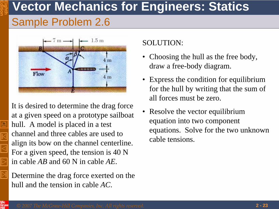
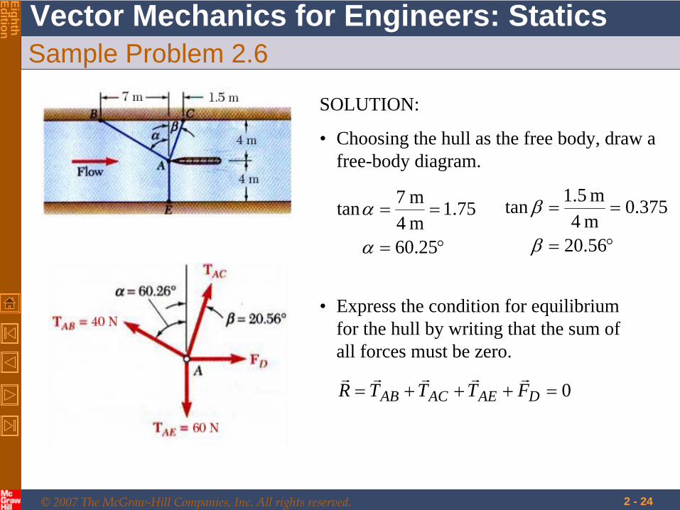
Sample Problem 2.6
It is desired to determine the drag force at a given speed on a prototype sailboat hull. A model is placed in a test channel and three cables are used to align its bow on the channel centerline. For a given speed, the tension is 40 N in cable AB and 60 N in cable AE.
Determine the drag force exerted on the hull and the tension in cable AC.
SOLUTION:
• Choosing the hull as the free body, draw a free-body diagram.
• Express the condition for equilibrium for the hull by writing that the sum of all forces must be zero.
• Resolve the vector equilibrium equation into two component equations. Solve for the two unknown cable tensions.
© 2007 The McGraw-Hill Companies, Inc. All rights reserved.
Vector Mechanics for Engineers: Statics
EighthEdition
2 - 24
Sample Problem 2.6
SOLUTION:
• Choosing the hull as the free body, draw a free-body diagram.
25.60
75.1m 4m 7tan
56.20
375.0m 4m 1.5tan
• Express the condition for equilibrium for the hull by writing that the sum of all forces must be zero.
0 DAEACAB FTTTR
© 2007 The McGraw-Hill Companies, Inc. All rights reserved.
Vector Mechanics for Engineers: Statics
EighthEdition
2 - 25
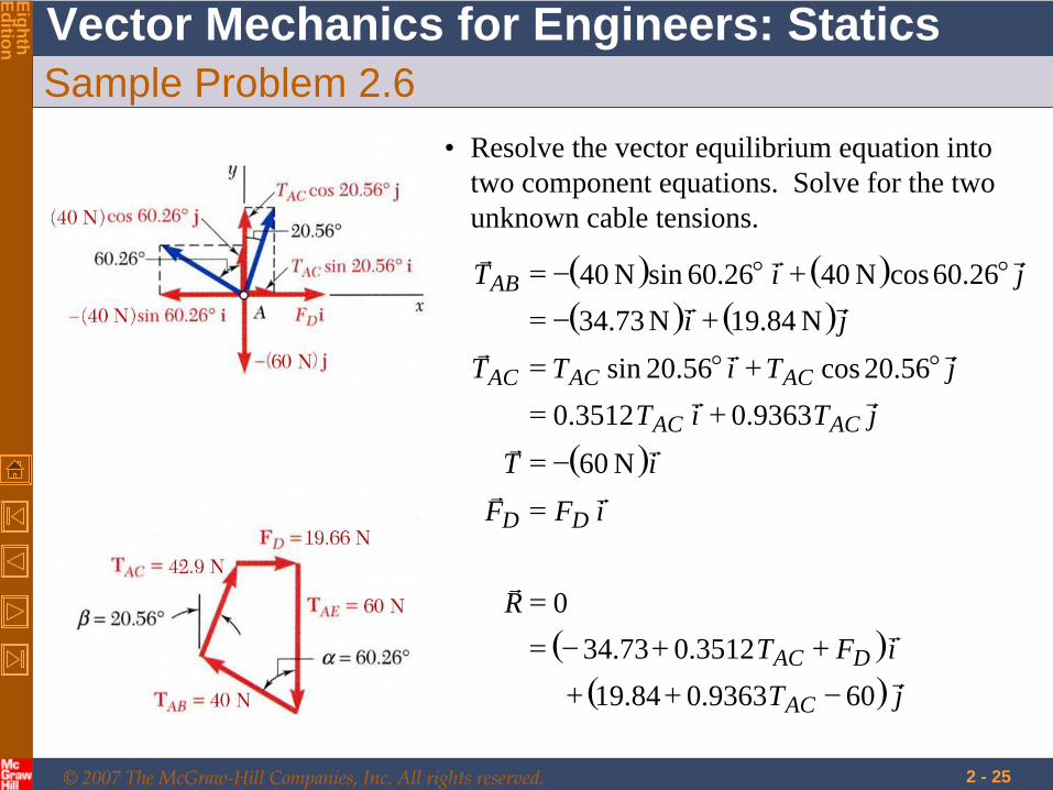
Sample Problem 2.6• Resolve the vector equilibrium equation into
two component equations. Solve for the two unknown cable tensions.
jT
iFTR
iFFiT
jTiTjTiTT
jijiT
AC
DAC
DD
ACAC
ACACAC
AB
609363.084.193512.073.34
0
N06
9363.03512.056.20cos56.20sin
N84.19N73.3426.60cosN4026.60sinN40
© 2007 The McGraw-Hill Companies, Inc. All rights reserved.
Vector Mechanics for Engineers: Statics
EighthEdition
2 - 26
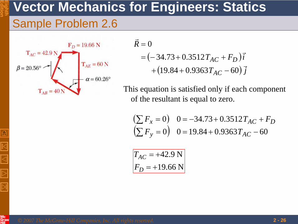
Sample Problem 2.6
jT
iFTR
AC
DAC
609363.084.193512.073.34
0
This equation is satisfied only if each component of the resultant is equal to zero.
609363.084.1900
3512.073.3400
ACy
DACxTF
FTF
N 66.19N 9.42
D
AC
FT
© 2007 The McGraw-Hill Companies, Inc. All rights reserved.
Vector Mechanics for Engineers: Statics
EighthEdition
2 - 27
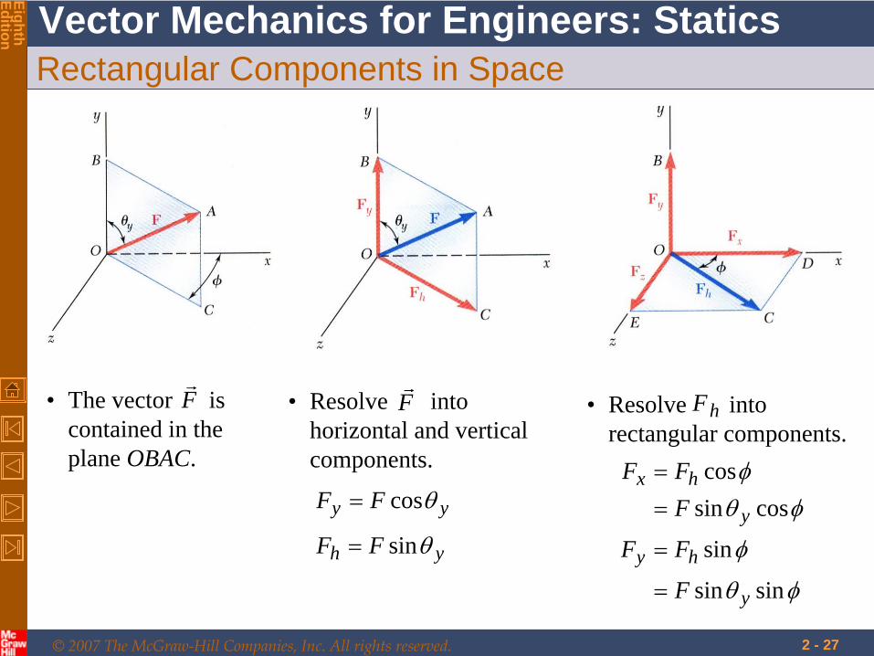
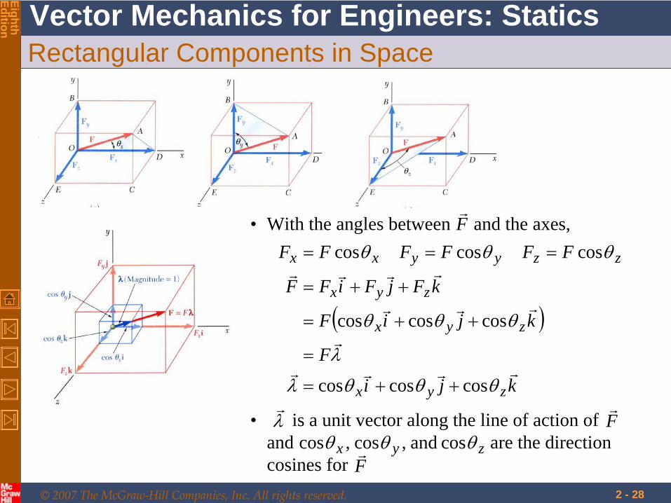
Rectangular Components in Space
• The vector is contained in the plane OBAC.
F
• Resolve into horizontal and vertical components.
yh FF sin
F
yy FF cos
• Resolve into rectangular components.
hF
sinsin
sin
cossincos
y
hy
y
hx
F
FF
FFF
© 2007 The McGraw-Hill Companies, Inc. All rights reserved.
Vector Mechanics for Engineers: Statics
EighthEdition
2 - 28
Rectangular Components in Space
• With the angles between and the axes,F
kji
F
kjiF
kFjFiFF
FFFFFF
zyx
zyx
zyx
zzyyxx
coscoscos
coscoscos
coscoscos
• is a unit vector along the line of action of and are the direction cosines for
F
F
zyx cos and,cos,cos

© 2007 The McGraw-Hill Companies, Inc. All rights reserved.
Vector Mechanics for Engineers: Statics
EighthEdition
2 - 29
Rectangular Components in Space
Direction of the force is defined by the location of two points,
222111 ,, and ,, zyxNzyxM
dFdF
dFd
Fd
FdF
kdjdidd
FF
zzdyydxxd
kdjdid
NMd
zz
yy
xx
zyx
zyx
zyx
1
and joining vector
121212
© 2007 The McGraw-Hill Companies, Inc. All rights reserved.
Vector Mechanics for Engineers: Statics
EighthEdition
2 - 30
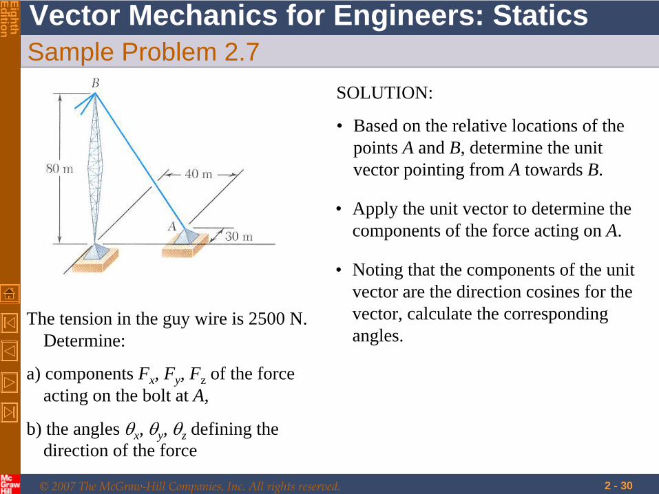
Sample Problem 2.7
The tension in the guy wire is 2500 N. Determine:
a) components Fx , Fy , Fz of the force acting on the bolt at A,
b) the angles x , y , z defining the direction of the force
SOLUTION:
• Based on the relative locations of the points A and B, determine the unit vector pointing from A towards B.
• Apply the unit vector to determine the components of the force acting on A.
• Noting that the components of the unit vector are the direction cosines for the vector, calculate the corresponding angles.
© 2007 The McGraw-Hill Companies, Inc. All rights reserved.
Vector Mechanics for Engineers: Statics
EighthEdition
2 - 31
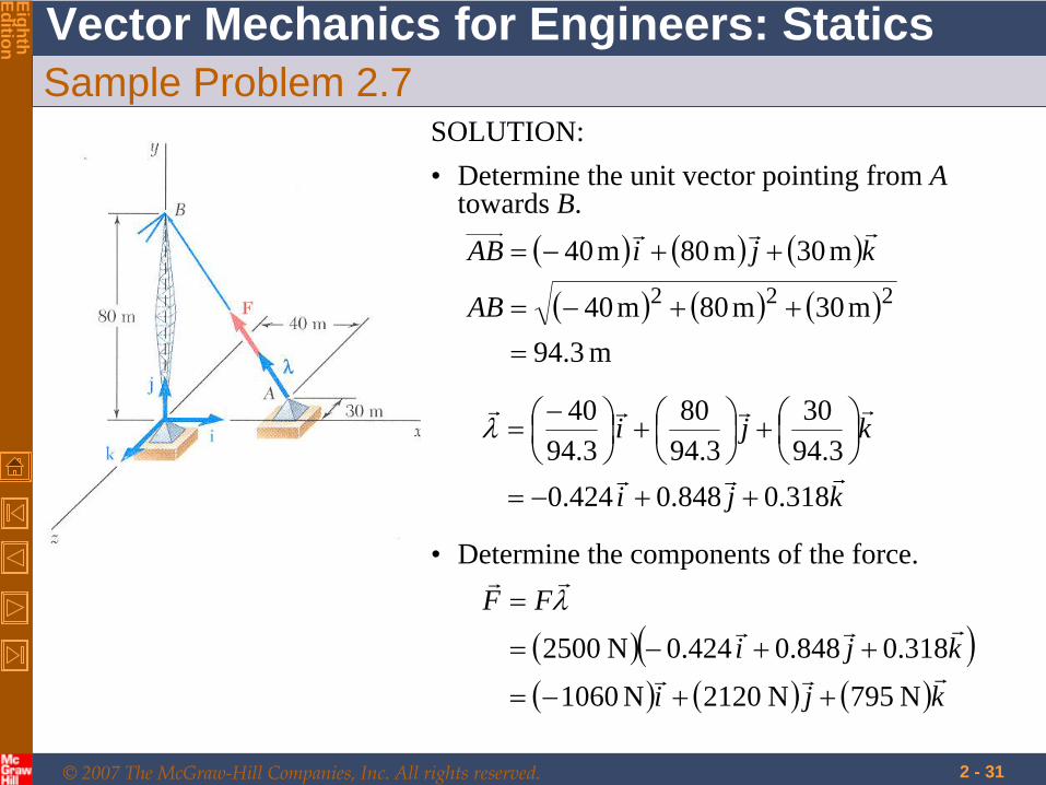
Sample Problem 2.7SOLUTION:• Determine the unit vector pointing from A
towards B.
m 3.94
m30m80m40
m30m80m40222
AB
kjiAB
• Determine the components of the force.
kji
kji
FF
N 795N 2120N1060
318.0848.0424.0N 2500
kji
kji
318.0848.0424.03.94
303.94
803.94
40
© 2007 The McGraw-Hill Companies, Inc. All rights reserved.
Vector Mechanics for Engineers: Statics
EighthEdition
2 - 32
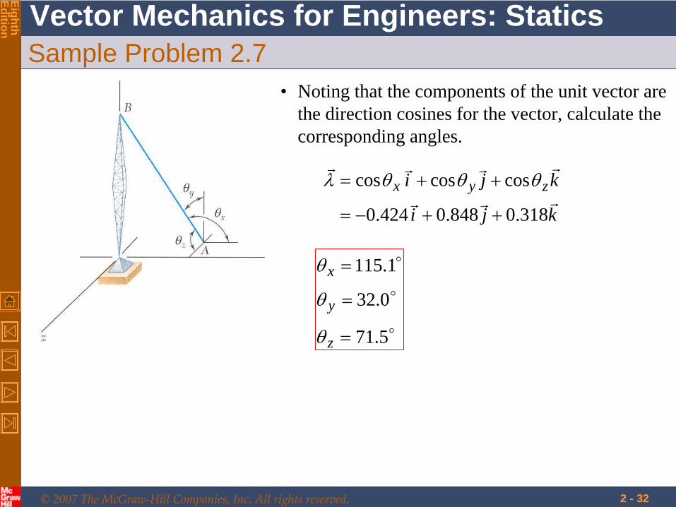
Sample Problem 2.7• Noting that the components of the unit vector are
the direction cosines for the vector, calculate the corresponding angles.
kji
kji zyx
318.0848.0424.0
coscoscos
5.71
0.32
1.115
z
y
x