Embed Size (px)
Citation preview

Chapter One: Introduction
1.1 Operating Environment
Operating system
Chinese/English Windows XP Windows Vista Windows7
Hardware Configuration
Pentium 1.5GHz or above
ROM: 256M
Chapter Two: To know software interface
LED Build Software is mainly used to edit various designs for light, set light sculpt and effect for LED
light project. This software has three interfaces.
2.1 Design edit interface
Double-click shortcut icon of software, or click “start”—“program”—“LED Build Software” to start
software.
Design edit interface (Main interface)
Design edit interface is the main interface, can enter into other two interfaces from this interface. In
design edit interface, you can create, edit, display and output design as controller data and so on. The
following is the toolbar. (Notice: before outputting controller data, light sculpt must be set up in light sculpt
window.)
Design edit toolbar
2.2 Lighting sculpt interface
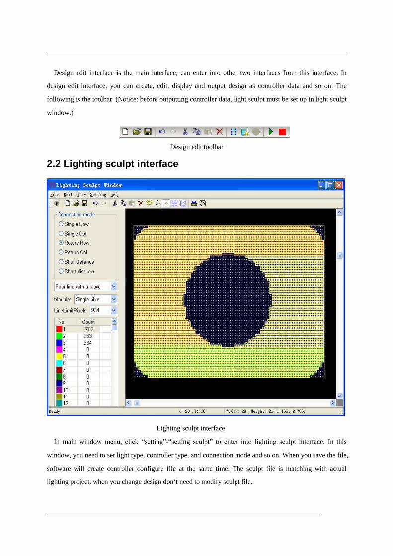
Lighting sculpt interface
In main window menu, click “setting”-“setting sculpt” to enter into lighting sculpt interface. In this
window, you need to set light type, controller type, and connection mode and so on. When you save the file,
software will create controller configure file at the same time. The sculpt file is matching with actual
lighting project, when you change design don‘t need to modify sculpt file.

Lighting sculpt toolbar
2.3 Effect interface
Effect interface
In main window menu click “setting” – “setting effect” to enter into effect interface. Function is to add
picture or video to design, then you can get more vivid effect.
Chapter Three: Light sculpt interface
Click menu “setting” – “setting sculpt”, enter LED light sculpt window, which is used to set the light
type and connection mode.
3.1 Connection mode
1. Single Row: line connected like “z” row by row
2. Signal Col: line connected like “z” column by column
3. Return Row: line connected like “ ” row by row

4. Return Col: line connected like “ ” column by column
5. Shortest distance: connect the nearest dot.
6. Shortest distance row: connect the nearest dot, considering the regularity of a row
3.2 Controller ports
Drag mouse in working area and several lines are added as follows:
When the pixel number of a port is more than the limit pixels number, the exceeded
pixels will be added to next port. The pixels number of a route (port) displays in the left
count list (as the right image shows).
3.3 Module
Signal pixel
3.4 Line limit pixels
When adding pixels to a route, if the pixel number is more than the limit number, then
the exceeded pixels will be added to next port.
3.5 Confirm line number of a slave controller
A port is a line. Choose a few lines to share a slave controller on the need of a few
ports. For example, we need three ports, and then select "three lines of one slave
controller" in the software. If select “two lines with a slave”, then line 1 and 2 are the first
slave controller, line 3 and 4 are the second controller, line 5 and 6 are the third slave
controller.
3.6 Connect route by background
For complex images, you can select “Connect by background” to assist design. Click “Setting” –
“Connect by background”. There are several methods to set background. There will be detailed

introduced in next chapter. After setting background, then add routes. Only the pixels in background
image can be connected.
Chapter Four: Lighting Sculpt Menu
Menu bar has five main menus in total: “file (F)”, “Edit (E) “,”View (V)”, “Setting(S)”, and “Help
(H)”
4.1 File menu
1.New :( Ctrl+N): create one blank sculpt file. After clicking, pop up a “setting size” dialog box.
The size unit is pixel. Enter the proper size according to actual engineering.
2.Open (Ctrl+O): open a sculpt file. Expanded-name is scu.
3.Save (Ctrl+S): save the sculpt file. Expanded-name is scu.
4.Save as: save the current sculpt as another file name.

5.Output H803SC Cfg file: output the configuration information of line1 and color palette as a *hmc
file. Music controller H803SC use this file to play designs with rhythm of music.
6.Output TA map: save sculpt as a map file. H802TA use this file to play designs with received
message.
7. Output image: Output image of sculpt as picture file.
8. Export display module: save module defined in software as *mod file.
9. Import display module: import *mod file.
10. Delete current display module: delete current display module from software.
11. Return: back to design edit window.
4.2 Edit menu
1.Undo: undo the previous operation
2. Redo: redo the previous operation
3. Cut: come into cut status, the mouse pointer become ,then select the demand pixels in
working area. The software will ask whether to delete the pixels within the area or not, after
clicking “Confirm”, all the pixels within the area will be deleted. However, the system clipboard
saved a copy which allows pasting times by using paste command.
4.Copy: come into copy status, the mouse pointer become ,then select the demand pixels in
working area. The selected pixels will be copied to system clipboard. This command is different
from cut command, it will not delete selected pixels.
5.Paste: come into paste status, mouse pointer become . Only when there are data in clipboard,
will this command be activaterd. Click mouse, the pixels of clipboard will be pasted to the
position. If you copy numbers of ports’ pixels, and choose one port when pasting, then all the

pixels in clipboard will be connected to the port. If you choose numbers of ports for pasting, then,
all the pixels will be connected to these ports..
6.Delete: come into delete status, mouse pointer become , select the pixels, then click “Confirm”
in the pop-up prompt dialog box to finish deletion.
7.Transfer: come into transfer status, and mouse pointer becomes a hand shape. Connect the selected
pixel and the following pixels to the end of current route.

8.Reverse: come into reverse status, and mouse pointer becomes an up arrow. Click the start end of
route, the mouse pointer becomes a down arrow, and then click the other end, the route will be
reversed. Means the pixels sequence of the route are reversed.
9.Add: come into adding route status. The mouse pointer becomes a crossing pointer. Or by clicking
right mouse in working area, can also come into adding route status. When the mouse moving

over the grid, the status bar will indicate the mouse position in grid, X indicates column, Y
indicates row. There are two methods to add route as below.
(1) Rectangle selection: It is suitable to regularly route within a rectangle; the rectangle size is
unlimited.
The specific method, please refer to chapter three.
Rectangle selection methods: First method: move mouse to the beginning position of demand
area, keep pressing left mouse key and drag mouse in working area, there will be a frame
displaying the height and width in status bar, release left mouse key until selecting all demand
pixels.
The four direction keys indicate four different directions. Meanwhile, press “+” or “-“can zoom
in or out.
(2) Click right: right-click on a grid dot, all the dots between the last dot of route to the
right-click dot will be added to the current route.
10. Array copy: Enter array copy status, mouse will become , after connection, drag the mouse to
rectangle the demand pixels in working area. Release mouse, pop up a dialog box, prompt for
entering the array unit number, enter number and click OK, array will be pasted according to
priority and connection mode , port number will increase automatically.
11. Save as a module: Save the defined route as a display module
12. Pixels repeat: add many pixels in one position, when the port number of each slave controller is
different, you can only select one line of a slave, use equally divide line method, and need to add
pixels.
13. Move: move pixels to another position.
4.3 View menu:
1.Image center: display image in center.
2.Show dialog bar: show or hide the dialog bar.
3.Show background image: show or hide the background image.
4.Show outline border: show or hide outline border.

5.Show grid: show or hide grid
6.Show route: show or hide route
Further more, presses ‘+’ button to zoom in, press ‘-’ button to zoom out, or scroll the mouse wheel to
zoom in or out.
4.4 Setting menu
1. Background setting:
(1). Edit background:Click “setting” – “background setting” – “edit background”, brush tool will be
embedded into window. Click “Image”—“Properties”, and then define the width and height of image. You
can use magnifier to zoom in. Click menu “View” – “Zoom” – “Show grid” to show grid on canvas. The
brush tool is helpful to design the route outline. Press “Esc” to return to sculpt window.

After setting up background image, you can connect pixels according to background
image. Choose “connect by background” on menu, as shown in below picture:
(2). Input Text: set front, character and size, then enter text, click “OK”.
(3). lead in from file: Lead in image file as background, pop up open file dialog box, select one image
file as background.
(4). Current frame: set the current frame from design window as background.
(5). Picture identify: software can automatically identify picture signified by circle or dot and create
background.
(6). Import dxf file: lead in the dxf file designed by AutoCAD software.
2. Delete background: delete background image.
3. Connect by background: add pixels only to the position with background
4. Background picture size: adjust size and start position of background picture
5. Port operation: implement exchange, combine and deletion on ports.
6. Light setting: set clock speed, grayscale grade, port number, Gamma, light type, IC type and color
reversion.
Click light setting, pop up “lighting setting” dialog box as follows.
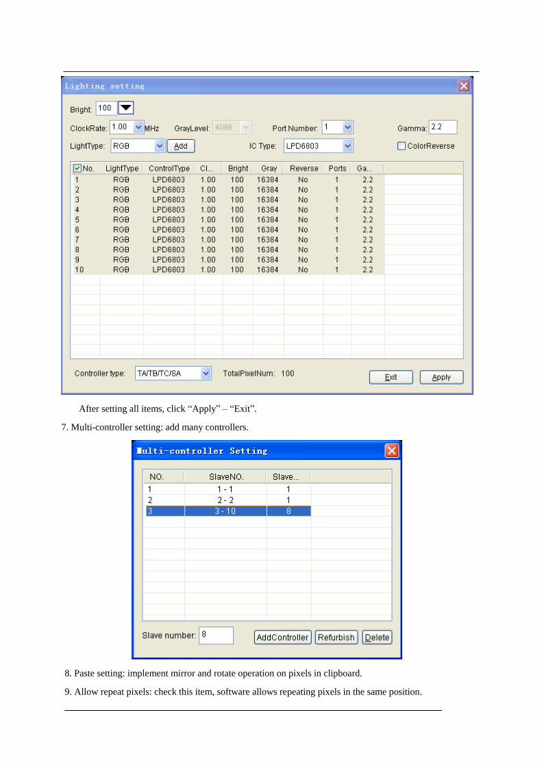
After setting all items, click “Apply” – “Exit”.
7. Multi-controller setting: add many controllers.
8. Paste setting: implement mirror and rotate operation on pixels in clipboard.
9. Allow repeat pixels: check this item, software allows repeating pixels in the same position.

10. Frame adjustment: allow adjusting the frames, namely the size of sculpt.
11. Encryption to controller: set password for controller.
Limit times: limit the power-on times, exceed the limit times, controller will be locked.
Encryption count: encryption times, select relieve encryption when decoding.
Chapter Five: Design edit interface
Design edit interface includes design board and color board.
5.1 Design board
Design board is used to create designs, which includes many kinds of actions. Each action includes lots
of modes.

☆ Recycling before a color: When choosing the item, moving empty part will be filled by moved out
color. Otherwise, it will be filled with palette’s color.
☆ Make frame number: Click action list to create the specified number of frames.
☆ Romance: When the default color of current action is not from palette, this item is valid.
☆ Step: moving scope of adjacent frames.
5.1.1 Moving
Moving has 10 modes, user can choose “Cycle the previous frame color”, set make frame number
and step.
Left: moving to left.
Right: moving to right
Up: moving up
Down: moving down
Top left: moving to top left
Down left: moving to down left
Top right: moving to top right
Down right: moving to down right
Inner port: moving as route of port. The item ignores block setting.
Inter port: In one port, all light in same color, the color moving among ports. The item ignore step.

5.1.2 Symmetry
Symmetry has six modes.
Horizontal open: color moves to the sides from center.
Horizontal close: color moves to center from the sides.
Vertical open: color moves to top and bottom from center.
Vertical close: color moves to center from top and bottom.
Twin corner open: color moves to two sides from center in the form of right angle.
Twin corner close: color moves to center from two sides in the form of right angle.
5.1.3 Interleaving
Interleaving has two modes:
Horizontal: the interlacing lines move from two sides to center.
Vertical: the interlacing columns move to center from top and bottom.
5.1.4 Diffusing
Diffusion has six modes.
Ellipse diffuse: color spreads around in elliptical shape.
Ellipse shrink: color shrinks in elliptical shape.
Rhombus diffuse: color spreads in rhombic shape.
Rhombus shrink: color shrinks in rhombic shape.
Rectangle diffuse: color spreads in rectangular shape.
Rectangle shrink: color shrinks in rectangular shape.
5.1.5 Rotation
Rotation has four modes.
Right-handed screw: color rotates in right-handed spiral shape.
Left-handed screw: color rotates in left-handed spiral shape.
Right circumrotate: color rotates clockwise.
Left circumrotate: color rotates anticlockwise.

5.1.6 Dropping
Dropping action has two modes. You can set the rendering mode.
Style 1: Drop from upside, color changes in accordance with the color change in palette.
Style 2: Unlike style 1, the dropping is white.
5.1.7 Toy bricks.
Toy bricks have 4 modes. You can set the rendering mode, width of bricks, height of bricks, space
between, frequency, overpass, and rebound height.
☆ Bricks width: Width of bricks.
☆ Bricks height: Height of bricks.
☆ Space between: The ratio of the number of a row of grids to the grids number of bricks. 1 means no
interspaces.
☆ Frequency: A row of bricks appear in certain frames. 0 means after a row of bricks are stacked, the
next row of bricks come out.
☆ Filtration: The bricks coming out from the first certain frames will be filtered.
☆ Rebound height: Rebound height of bricks.
Left: bricks move left.
Right: bricks move right.
Up: bricks move up.
Down: bricks move down.
5.1.8 Sound wave
Sound wave has 4 modes. You can set the rendering mode. Music note beats with color in palette.
Left: music note bound left.
Right: music note bound right.
Up: music note bound up.
Down: music note bound down.

5.1.9 Picture and text.
Picture and text action have 2 modes. Can set text, text direction, font, color, and stunt, make frame
number and romance. Also can browse, delete or edit picture file and text file.
Ⅰ.Input text
1. Input text in text edit dialog, as following picture shows “Merry Christmas”. Then choose horizon or
vertical. Click “font” to set text, finally click “Build Picture”, a Text.bmp fill appears in the file list
2. Select the Text.bmp file, then Click edit button, the brush tool will be opened. Use the brush tool to
edit the picture or text. If dissatisfy the picture or text, you can delete it in order to make a new picture or
browse file. As following, use brush tool to paste a picture in left, click grey area to active brush tool, then
press “ESC” to exit brush tool.
3. Click style 1 or style 2 in action list. Style 1: move to left or up. Style 2: move to right or down.
Ⅱ. Browse picture and text files.
1. Click browse button, add pictures or text files to file list.
2. Choose a file, you can press delete button to delete it or press edit button to edit it.
3. Choose stunt or romance, enter frames number, and click style 1 or style 2.
5.1.10 Gradual changing

Gradual changing has 6 modes.
Brighten: change the current frame to white gradually.
Darken: change the current frame to black gradually.
Inflate: change the current frame bigger gradually.
Deflate: change the current frame smaller gradually.
Fade out: change the current frame to background color gradually.
Transition: the whole frame change color as palette.
5.1.11 Jalousie
Jalousie has 4 modes, can set block number and romance.
Left: close the jalousie to left in block number.
Right: close the jalousie to right in block number.
Up: close the jalousie up in clock number.
Down: close the jalousie down in clock number.
5.1.12 Others
Others actions include particle, diffuse, line type, random, and wave.
Particle: can set the frame number, romance and the following parameters.

5.2 Color board
Color plate is used to set palette, default palette is full color.
Background: Set background color, the default color is black.
Color: Set the current color.

Transition grade: The difference value of adjacent colors.
Transitional colors: The color number from current color transited to target color.
Total: The total number of color in palette
Clear: Delete all colors in palette.
Delete: Delete the last color in palette.
Save: Save the current palette to sample color list.
Color pad library: select configured color pad from library.
Remove: Delete the palette from color pad library.
5.2.1 Use color buttons
Click color button, the color plate will pop up, mouse becomes a straw, the left bottom of color
select box displays the color where the mouse is located in, and under the box displays the value of red,
green and blue. Select and click the color. If the needed color is not in the plate, you can click the button on
the right bottom of box to select color.
5.2.2 Set palette
1. Click “clear” to delete all colors in palette.
2. Add one color:
☉ Click on palette to add the current color to palette.
☉ Click “Color”, select color in the pop-up color plate. The selected color will cover current color and
be added to palette.
☉ Click on color grid, the selected color will be added to palette.
3. Add transitional color
☉ Keep pressing “Ctrl”, click on palette, the last selected color will transit to the current color in
specified color difference value.
☉ Keep pressing “Ctrl”, click “Color”, select color in the pop-up plate, the selected color will substitute
the current color, meanwhile, the last selected color will transit to the current color in specified color
difference value.
☉ Keep pressing “Ctrl”, click on plate grid, the last selected color will transit to the first selected color
in specified color difference value.
4. Add transitional color
Drag mouse in color plate, the selected colors will be added to palette.
5. Select from sample color library.
Click sample color library, select the needed palette from the list.
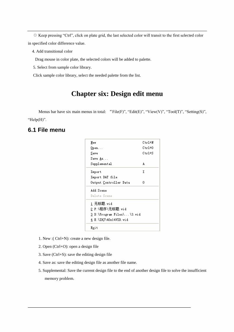
Chapter six: Design edit menu
Menus bar have six main menus in total: “File(F)”, “Edit(E)”, “View(V)”, “Tool(T)”, “Setting(S)”,
“Help(H)”.
6.1 File menu
1. New :( Ctrl+N): create a new design file.
2. Open (Ctrl+O): open a design file
3. Save (Ctrl+S): save the editing design file
4. Save as: save the editing design file as another file name.
5. Supplemental: Save the current design file to the end of another design file to solve the insufficient
memory problem.

6. Import: can import video file, SWF file and VID file. After selecting file, it displays the width,
height, frames number, enter frames number, select import mode, and click open. If frame
number of SWF file is large, select high speed import SWF.
If select “Output controller data”, click open, software will output file as DAT file.
7.Import DAT file: create VID file based on the imported DAT file, only support TA/TB/TC/SA
8.Output controller data: create data file based on edited design file, the expanded-name is *.dat.
9. Add scene: add a new scene, which includes sculpt and design file.
10. Delete scene: delete scene. File
11. Exit: exit the software.
6.2 Edit menu
1. Undo: undo the previous operation
2. Redo: redo the previous operation.

3. Cut: Enter start frame and end frame in the pop up dialog box, and then click “OK”.
☉ In block mode, it will delete the color within the appointed frames, and copy to system clipboard.
☉ Not in block mode, it will delete the appointed frames, and copy to system clipboard.
4. Copy: Input start frame and end frame in the pop-up dialog box.
☉ Select “copy to clipboard”, the appointed frames will be copied to system clipboard.
☉ Select “repeat time of every frame”, and input value. Then, the appointed frames will repeat as
times as set.
5.Paste: in opened dialog box, you can set paste position, paste times, paste mode, paste direction and
reverse order.
☆ Place: paste after which frame
☆ Times: repeat paste times of frames from clipboard.
☆ Mode: You can select insert or overlay. If select overlay, then you may choose the sub-modes.
☉ Normal: Copy source frame to the aim frame.
☉ Unite: Combine source frames and aim frames together by Boolean OR.
☉ Or: Combine source frames and aim frames together by Boolean XOR.
☉ Superposition: Combine source frames and aim frames together in certain proportion.

☉ Transparency: if the pixels of source frames are black, then displays aim frame pixel.
Otherwise, displays the source frame pixel.
☆ Paste direction: paste direction of data.
☉ Originally: Same direction with clipboard data.
☉ Horizontal mirror: horizontal mirror of clipboard data.
☉ Vertical mirror: vertical mirror of clipboard data.
☉ Center mirror: center mirror of clipboard data.
☆ Reverse: reverse frame order in clipboard.
6.Delete: to delete the appointed frames
7.Color process: it has 6 ways; click OK after setting frame range.
☆ Color replace: replace the color of appointed frames with another color.
☆ Color member swap: turn the RGB color combination of appointed frames into another
combination.
☆ Color bright adjust: adjust the brightness of three colors.
☆ Clear not lighting of point: delete pixels without light.

☆ Clear pixels corresponding to black pixels of current frame: in the appointed frames, if the pixels
corresponding to current frame black pixels, they will be deleted.
☆ Converted to black and white images: convert the current full-color image or video into black and
white image.
8. Insert frames: insert a blank frame, use the current background.
6.3 View menu
1.Image center: display the image in center.
2.Dialog bar: show or hide the dialog bar
3.Show grid: show or hide the grid.
4.Status bar: show or hide status bar
6.4 Tool menu
1.Play: play design file.
2.Stop: stop playing design file.
3.Paint edit: use built-in brush tool to edit frame.
4.Video capture transform: to capture certain area in PC display, and transform to frame data, can
also directly open video file or SWF file.

Drag the capture window onto the wanted picture or video, also can set the capture region(X, Y) in
the dialog. Drag the border to modify the size of capture window, or set the window size in dialog.
Speed: frames number captured per second.
Frame number: all frame number in total, set by yourself
Click “Capture”, to start capturing, software will stop itself when reach up to frame number. When
capturing, you can press “Stop” to stop capturing.
Click “Play”, to play the captured design. Click “Stop” to stop playing.
Click “Delete”, pop up a dialog to input start and end frame.
Click “Save”, to save the captured animation as design file or AVI file.
Click “Open”, to open saved design file or video file. (AVI, MPG, ASF, RM etc.) If open video file,
it will only read frames within appointed number.
Click “OK”, to add the opened or captured animation to the current design file.
5. Unit file: can merge DAT files or VID files. Uniting DAT file includes two modes:
increase frame number, and increase slave controller number. Uniting VID file includes
two modes: horizontal and vertical.

6.5 Setting menu
1.Block: set operation area, otherwise, operation area will be the whole frame.
2.Cover mode: shift between cover mode and insert mode.
3.Setting sculpt: enter into lighting sculpt setting window.
4.Setting effect: enter into effect setting window.
5.System setting: setting parameters of software.

Compressed files to store documents: store the design directly will occupy a lot of disk space. Select
this item, the file size will be shrunk to dozens, hundreds or thousands times smaller.
Grid scale: set the width and height of grid
External painting tools: select external painting tool from computer.
5.Language: set language of software.
6.Skin: set software style.
6.6 Help menu
1.Help: help file of the software.
2.About: company and software information.
Chapter Seven: Design edit and create data
7.1 Create new file
Click “File”—“New” to create a new file.

7.2 Set color
1. Set current color
Click current color button, select color from the pop-up color box.
2. Set background color
Click background color button, the new created frames take this color as background color.
3 .Set palette (Please refer to chapter 5.2)
7.3 Add design
There are two methods to add design.
1. Video capture
Click menu “Tool”—“Video capture”, pop up capture window and video capture transform
window.
Drag the capture window above the wanted picture or animation, also can move the capture
window by setting capture region (position of X, Y). You can also set the height and width of capture
window in capture window. And then set the speed (frame number per second) and frame number in
total. Click “Capture” button (shortcut key is Ctrl+Alt+F5) to begin capturing. You can click “Stop”
Palette

to stop capturing (shortcut key Ctrl+Alt+F7).Click “Play” button to play the captured animation,
click “Smooth zoom” to smooth the animation, click “Stop” button to stop playing.
Click “Delete” button, pop up a dialog box, enter frame number to delete the appointed frames, or
click “First Frame” – “Last Frame” to delete all frames. Then click “Ok”.
Click “Open” button to open a *.vid file, click “Save” button to save the captured animation as .vid
file. Click “Ok” button to add the captured animation to the editing design file.
2.Design board

Software provides 12 actions such as moving, symmetry etc. Each action includes various modes.
Shortcut key is corresponding to ‘1’ – ‘8’.
Select one action, input making frame number, then select modes in list or press the corresponding
shortcut key to create design.
In toy bricks’ action, you can set the toy bricks’ size, “space between” means the distance of adjacent
line of toy bricks. Frequency means the distance of adjacent two rows of bricks. Overpass means row
number of bricks that are not accumulated.
Rebound height means the rebound height when bricks hit the bottom.
In text action, click “Font” button, pop up “Font” dialog box, you can set the font of text.
7.4 Edit
1.Click menu “Tool” – “Paint edit”, come into brush edit status, you can edit the current frame by
using brush tools, press “ESC” to return to main window.
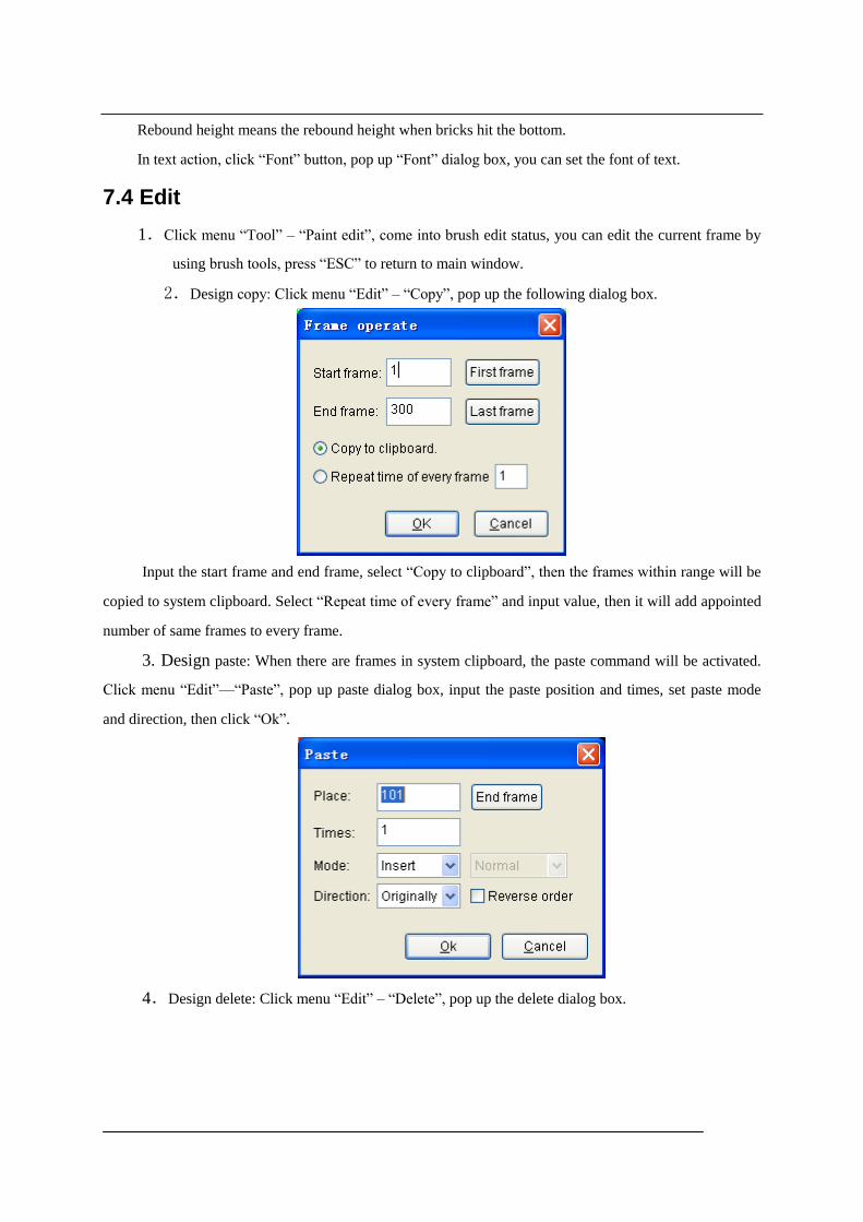
2.Design copy: Click menu “Edit” – “Copy”, pop up the following dialog box.
Input the start frame and end frame, select “Copy to clipboard”, then the frames within range will be
copied to system clipboard. Select “Repeat time of every frame” and input value, then it will add appointed
number of same frames to every frame.
3. Design paste: When there are frames in system clipboard, the paste command will be activated.
Click menu “Edit”—“Paste”, pop up paste dialog box, input the paste position and times, set paste mode
and direction, then click “Ok”.
4.Design delete: Click menu “Edit” – “Delete”, pop up the delete dialog box.

Input start frame and end frame, choose “Delete appoint range of all frame” to delete the appointed
frames. Choose “Space frame numbers” will delete one frame every several frames.
5.Color process: Click menu “Edit” – “Color process”, pop up a dialog as below
Input start frame and end frame in the right, color replace means replace the color with another color.
Color member swap means changing color among the RGB three colors. Color bright adjust means to
adjust brightness of three colors. Clear not lighting of point means to delete pixels without lighting.
Clear pixels corresponding to black pixels of current frame: take the current frame as template, clear
pixels corresponding to black.
Converted to black and white images: convert the current image to black and white image.

6.Set block: Click menu “setting” – “Block”, pop up block panel as below, move mouse to
working area, mouse pointer become crossing, drag mouse to select an area, there will be a frame, then all
operation will be valid only within the selected area.
7.5 Data created
Click “File”—“Output controller data”, pop up the select frame range dialog box, start frame must be 2,
then click “last frame” – “OK”. Then input save path and file name. The expanded-name is *.dat.

Chapter eight: Effect setting
Click menu “setting” – “setting effect”, enter into effect setting window.
1. Import gridding: click menu “file” – “import gridding”, pop up the import gridding dialog box.
Can choose "Tile Horizontal" "Tile vertical" " Tile cross" "Fan-shaped array" "triangular array", enter
line number and row number of import grid, the starting angle, interval angle, line spacing, line number,
choose Meta doubling, Meta shapes, and then enter horizontal spacing, Meta size and vertical interval,
finally click "ok" button.
2. Layer: click "new" button in layers bar to create a new layer; Click "delete" button to delete selected
layer; the selected layer is the current layer, only the current layer can be edited and moved; click "up"
button, the current layer will be moved up; click "down" button, the current layer will be moved down.
3. Drawing tool: drawing tool includes selection, text, line, curve, ellipse, rectangle, rounded rectangle,
pictures and video. Choose a layer first, select a drawing tool and then click or drag in the working area.

Meta will appear on the layer. Use the selection tool, by clicking and dragging can choose a meta, the rapid
panel can display the selected meta color, line width, position, size, and the corresponding grid, can change
the values, also can use the mouse to move meta and change size of meta.
4. The combination and cancel combination: choose the to be combined meta, click menu "edit" --
"combine" would combine the selected meta into a meta; select a combined meta, click menu "edit" --
"cancel combine" to dismiss the meta.
5. Rectangle into segment: choose a number of rectangles, click menu "edit" -- "rectangle into segment",
then each rectangle becomes into four segments.
6. Map grid point: establish a corresponding relationship between grid points and meta, the column and row
value of grid point corresponding to the meta that are not mapped is (0, 0), always be itself colors when
playing, the playing color of meta is synchronized with color of corresponding grid.
7. Rotation and zoom: select meta, click menu “tool” – “transform”, pop up a rotation zoom dialog box. It
has move, rotate, concentric zoom, and mirror options, click “apply” to change the selected meta, click
“copy application” button to create a copy for meta and conduct zoom operation on copy.
8. Meta layer list: click menu “dispose” – “Meta list”, pop up the Meta list, you can check meta on every
layer, you can select meta and move meta to other position and other layers.
9. Return to main window: click menu “file” – “return to main window”.
Chapter Nine: Sample I
A. Start “LED Build software”, click “setting”—“setting sculpt”, enter into Lighting Sculpt
Interface.
B. In Lighting Sculpt Interface, set lighting sculpt.
1.Click “File”—“New”
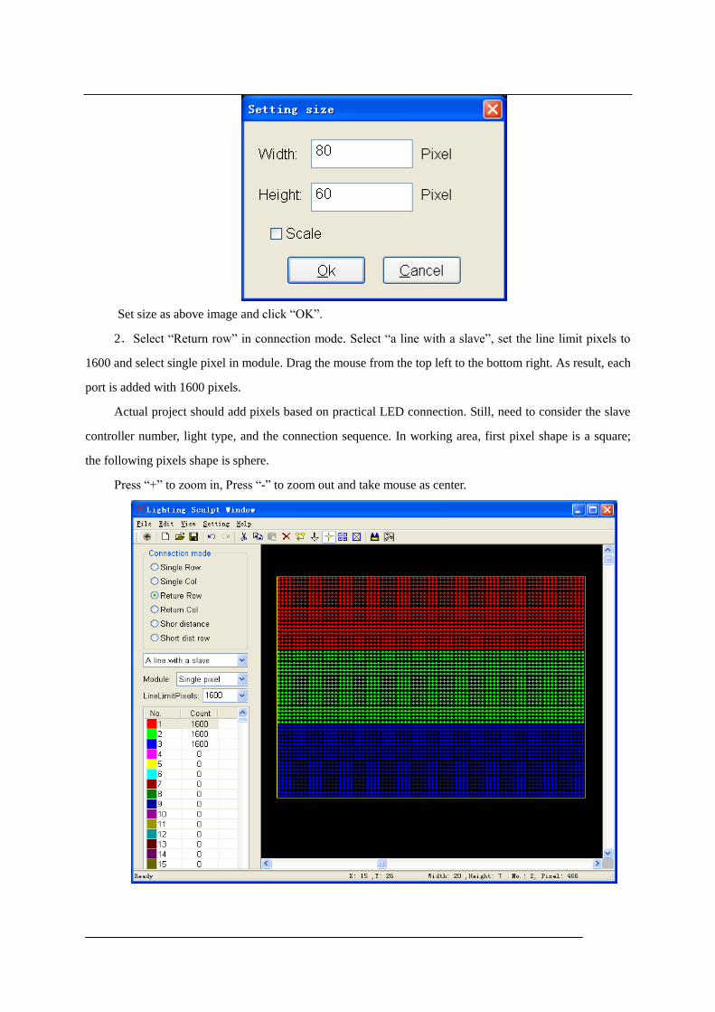
Set size as above image and click “OK”.
2.Select “Return row” in connection mode. Select “a line with a slave”, set the line limit pixels to
1600 and select single pixel in module. Drag the mouse from the top left to the bottom right. As result, each
port is added with 1600 pixels.
Actual project should add pixels based on practical LED connection. Still, need to consider the slave
controller number, light type, and the connection sequence. In working area, first pixel shape is a square;
the following pixels shape is sphere.
Press “+” to zoom in, Press “-” to zoom out and take mouse as center.

4.Click “setting”—“Lighting Setting”, pop up a lighting setting dialog box, set up every option , then
click “Apply” – “Exit”.
5.Click menu “File”—“return”, click “yes” in the pop-up dialog box.
Input file name “Example”, click “save”, then the lighting sculpt is saved as Example.scu file.
C. Returned to main interface, begin to make design.
1.Click “Color”, select color from sample color list, it will be the palette color.
2.Click “design”, select “interleaving” in action list. Set make frames number to 99, then click
“Horizon” or press shortcut key 1.

3.Click “Tool”—“Video capture”, pop up video capture window. Set capture frame number to 200,
play a video, move the window onto video, then click “capture”, software will stop capturing after frame
number is up, then click “OK” to add the 200 frames to design file.
4.Click “Color”, select transition grade and set it to 32, click “Clear”, click pink in color plate, keep
pressing Ctrl, click white, then click pink and release mouse.
5.Click “Design”, select “Toy bricks” in action list, romance select “up”, width 2, height 2, space 3,
frequency 5, overpass 0, and rebound height 0. Click “Down” in the modes list to make 451 frames.
6.Select “Picture & text”, stunt choose “push left”, click “Browse” to open a picture file. Finally, click
style1 in mode list to make 280 frames.
7. Delete first frame: click “Edit”—“Delete”, pop up a dialog box, set the start frame and end frame to
1, select “Delete appoint range of all frame”, click “OK”.
8.Click “File”—“Save”, to save the file.
D. Add fixed position and changing color text on previous design.
1.Start another “LED Build software”.
2.In the second software, click menu “setting”—“setting sculpt”, enter into sculpt interface, create
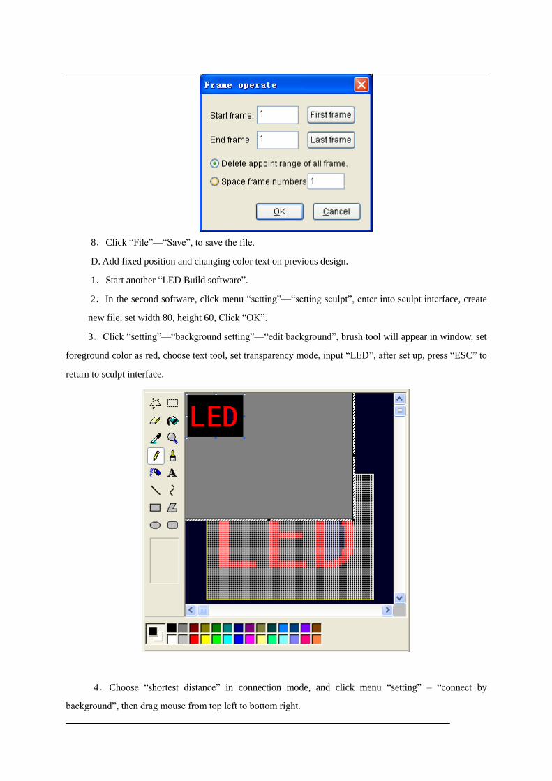
new file, set width 80, height 60, Click “OK”.
3.Click “setting”—“background setting”—“edit background”, brush tool will appear in window, set
foreground color as red, choose text tool, set transparency mode, input “LED”, after set up, press “ESC” to
return to sculpt interface.
4.Choose “shortest distance” in connection mode, and click menu “setting” – “connect by
background”, then drag mouse from top left to bottom right.
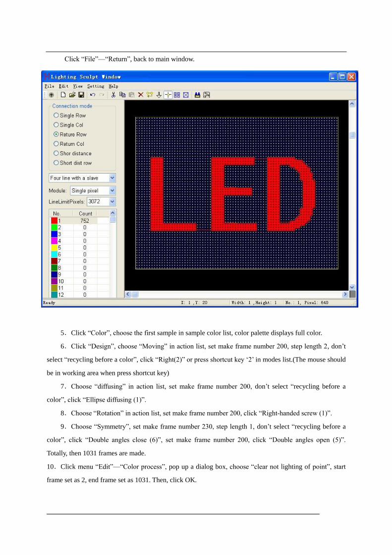
Click “File”—“Return”, back to main window.
5.Click “Color”, choose the first sample in sample color list, color palette displays full color.
6.Click “Design”, choose “Moving” in action list, set make frame number 200, step length 2, don’t
select “recycling before a color”, click “Right(2)” or press shortcut key ‘2’ in modes list.(The mouse should
be in working area when press shortcut key)
7.Choose “diffusing” in action list, set make frame number 200, don’t select “recycling before a
color”, click “Ellipse diffusing (1)”.
8.Choose “Rotation” in action list, set make frame number 200, click “Right-handed screw (1)”.
9.Choose “Symmetry”, set make frame number 230, step length 1, don’t select “recycling before a
color”, click “Double angles close (6)”, set make frame number 200, click “Double angles open (5)”.
Totally, then 1031 frames are made.
10.Click menu “Edit”—“Color process”, pop up a dialog box, choose “clear not lighting of point”, start
frame set as 2, end frame set as 1031. Then, click OK.

11.Click menu “Edit”—“Copy”, pop up a dialog box, set as follow, and click OK.
E. Close the second software. In first software click menu “Edit”—“Paste”, set as follow, and then
click “OK”.

Chapter Ten: Sample II
A. Start<<LED Build software>>, click “setting”—“setting sculpt” to enter into Lighting Sculpt
Interface.
B. In the Lighting Sculpt Interface, set sculpt.

1.Click menu “File”—“New”
Set up size and click “OK”.
2.Select “return column” in connection mode, set “a line with a slave” and set line limit pixels to
1200, then drag mouse in working area from top left to bottom right, add 1200 pixels to port of slave
controller.
3. Click menu “setting”—“Lighting Setting”, open the lighting setting dialog, set up each option
according to actual property of light.
4. Save lighting sculpt file, click menu “File”—“Return”
C. Create Design
1.Click “Color”, select first sample from sample color list, it will be the palette color.
2.Click “design”, select “Sound wave” in action list. Make frames number set 100, romance Not, and
then click “Up (3)” to make 100 frames.
3.Click menu “setting”—“Block”, drag mouse in working area, adjust the block, and select area (0, 0,
20, and 30).
4.Click menu “Edit”—“Copy”, pop up a dialog box, set start frame 2, end frame 101, choose “Copy

to clipboard, and then click “OK”.
5.Click menu “setting”—“Block” again to cancel block setting.
6.Click menu “Edit”—“Paste”, pop up a paste dialog box, set as follows, and click OK.
Pop up the following info dialog box, click “yes”
The 102nd
frame is copied from 2nd
frame, changing effect is as follows:
From the above 2 pictures, we can find the sound wave become broader, it is for illustrating the paste
operation.
D. Make a layer on the create design.
1.Enter into lighting sculpt window, click New, open a dialog, click OK to clear all pixels.
2.Click “setting”—“background setting”—“Lead in from file”, choose a picture from your PC, as
follow:
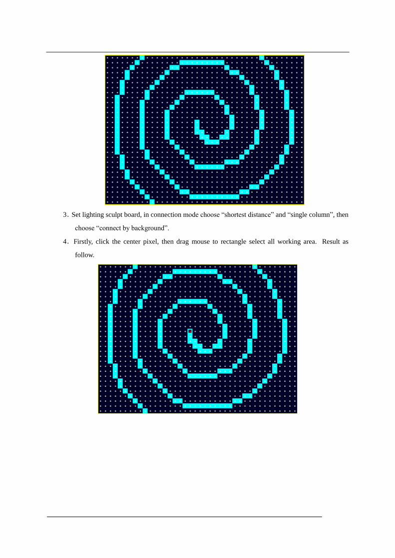
3.Set lighting sculpt board, in connection mode choose “shortest distance” and “single column”, then
choose “connect by background”.
4.Firstly, click the center pixel, then drag mouse to rectangle select all working area. Result as
follow.

This sculpt is only for design setting, don’t need to set lighting property, you can return to main
window directly.
5.Click “Color”, set palette as blue green blue transition.
6.Move the control bar to the first frame.
7.Click “Design”, choose “Moving” in action list, set make frame number 200, step length 1, don’t
select “recycling before a color”, then click “Inner port (9)”.
8.Click menu “Edit”—“cut”, open a dialog, set start frame 2, end frame 201, then click OK.
9.Click menu “Edit”—“Paste”, set as follow, and click “OK”.

When overlay design is finished, effect as follow.
E. Add more design
1.Move the control bar to the end, namely the 201st frame, Click “Color”, choose the first sample (full
color) for color palette.
2.Click “Design”, choose “Dropping” in action list, romance not, set filter number 10, which means
10 drops will disappear. Click “Style 2 (2)”
3.Choose “Gradual changing” in action list, set romance Not, make frame number 20. Click “Fade out
(5)”
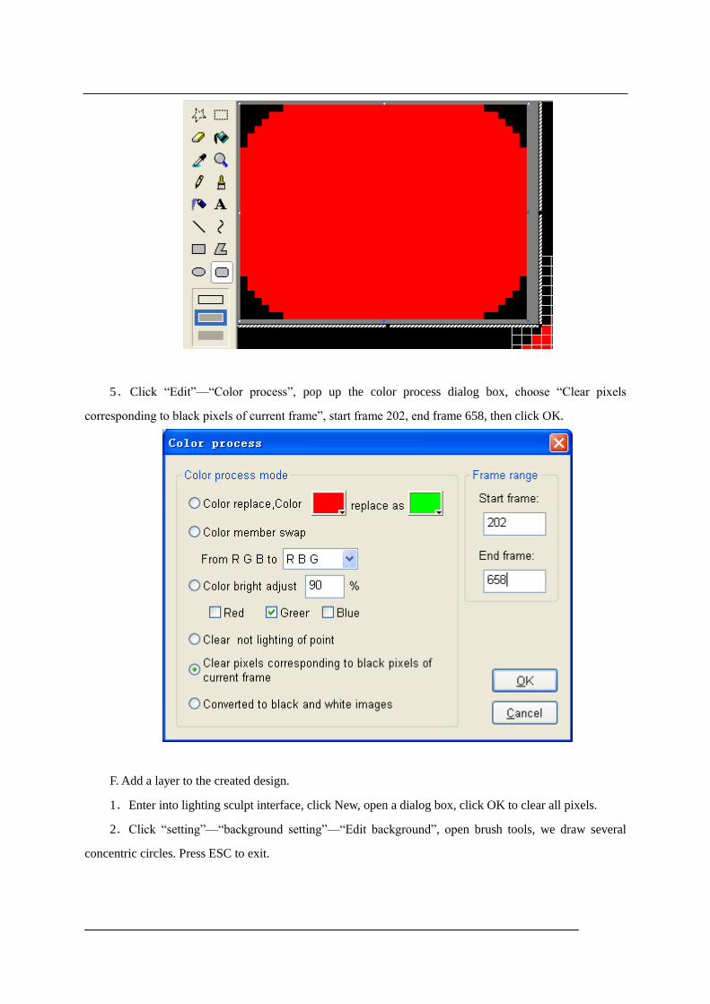
4.Click menu “Control”—“Paint edit”, draw a rectangle with rounded corner, background is black.
Press ESC to exit.
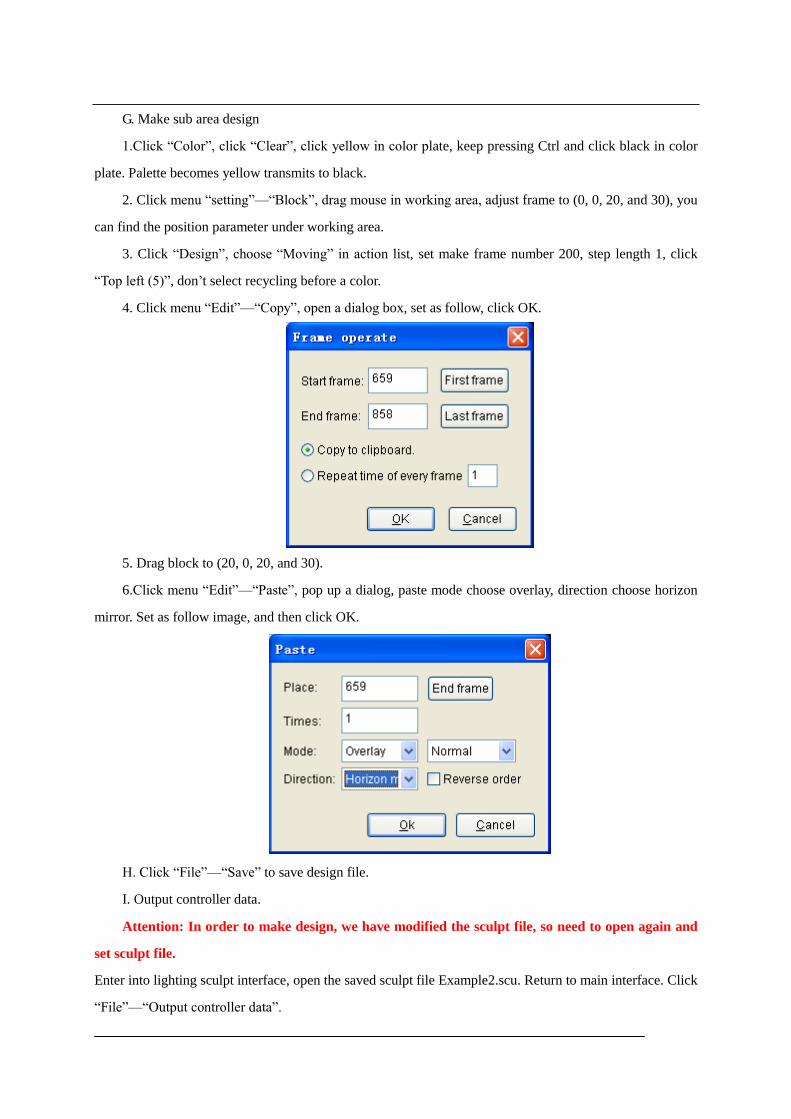
5.Click “Edit”—“Color process”, pop up the color process dialog box, choose “Clear pixels
corresponding to black pixels of current frame”, start frame 202, end frame 658, then click OK.
F. Add a layer to the created design.
1.Enter into lighting sculpt interface, click New, open a dialog box, click OK to clear all pixels.
2.Click “setting”—“background setting”—“Edit background”, open brush tools, we draw several
concentric circles. Press ESC to exit.

3.Choose “shortest distance” and “single column” in connection mode, then choose “connect by
background”, choose the first port in port number list.
4.Drag mouse from the top left to bottom right in working area.
5.Click menu “Edit”—“transfer”, choose the 2nd
port in port number list, click the first pixel of 2nd
circle, then it become the 81st pixel of first port, as the yellow arrow marked. Choose the third port in port
number list, click the 1st pixel of the 3
rd circle, then it become the 53
rd pixel of 2
nd port, as blue arrow

marked.
6.Return to main interface, click menu “setting”—“Cover mode”, set 202nd
frame as the current
frame.
7.Click “Color”, click “Clear”, select red, green, and blue for palette.
8.Click “Design”, choose “Moving” in action list, set romance Not, make frame number 455, step
length 1, not recycling before a color, click “Inter port (0)”.
G. Make sub area design
1.Click “Color”, click “Clear”, click yellow in color plate, keep pressing Ctrl and click black in color
plate. Palette becomes yellow transmits to black.
2. Click menu “setting”—“Block”, drag mouse in working area, adjust frame to (0, 0, 20, and 30), you
can find the position parameter under working area.
3. Click “Design”, choose “Moving” in action list, set make frame number 200, step length 1, click
“Top left (5)”, don’t select recycling before a color.
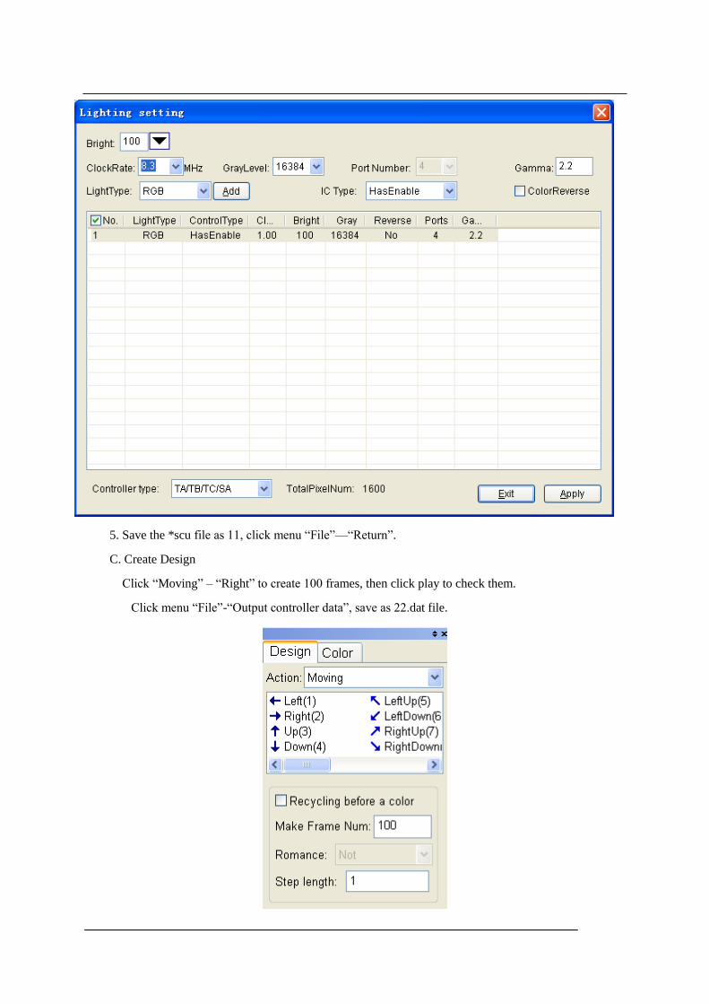
4. Click menu “Edit”—“Copy”, open a dialog box, set as follow, click OK.
5. Drag block to (20, 0, 20, and 30).
6.Click menu “Edit”—“Paste”, pop up a dialog, paste mode choose overlay, direction choose horizon
mirror. Set as follow image, and then click OK.
H. Click “File”—“Save” to save design file.
I. Output controller data.
Attention: In order to make design, we have modified the sculpt file, so need to open again and
set sculpt file.
Enter into lighting sculpt interface, open the saved sculpt file Example2.scu. Return to main interface. Click
“File”—“Output controller data”.

Chapter Eleven: Easy example
Sample 1:
Take guardrail tube as example, IC is DM134 with OE.
A. Start “LED Build software”, click menu “setting”—“setting sculpt” to enter Lighting Sculpt
Interface.
B. In Lighting Sculpt window, set lighting sculpt.
1.Click “File”—“New”
Set width and height, click “OK”.
2. Select “four line with a slave”, line limit pixels is 400
3. Drag the mouse from top left to bottom right. As shown in following picture, four ports have each
400 pixels.

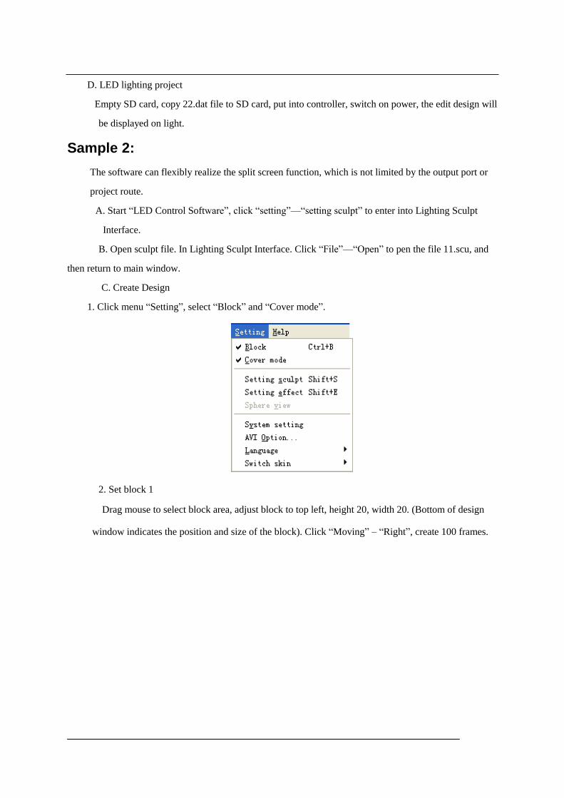
4.Click menu “setting”—“Lighting Setting”, open the lighting setting dialog box, Set parameters as
the following picture. Click “apply” – “Exit”.
5. Save the *scu file as 11, click menu “File”—“Return”.
C. Create Design
Click “Moving” – “Right” to create 100 frames, then click play to check them.
Click menu “File”-“Output controller data”, save as 22.dat file.
D. LED lighting project
Empty SD card, copy 22.dat file to SD card, put into controller, switch on power, the edit design will
be displayed on light.
Sample 2:
The software can flexibly realize the split screen function, which is not limited by the output port or
project route.
A. Start “LED Control Software”, click “setting”—“setting sculpt” to enter into Lighting Sculpt
Interface.
B. Open sculpt file. In Lighting Sculpt Interface. Click “File”—“Open” to pen the file 11.scu, and
then return to main window.
C. Create Design
1. Click menu “Setting”, select “Block” and “Cover mode”.
2. Set block 1
Drag mouse to select block area, adjust block to top left, height 20, width 20. (Bottom of design
window indicates the position and size of the block). Click “Moving” – “Right”, create 100 frames.

3, Set block 2
Adjust the block to the top right, height 20, width 20. Drag the scroll bar to 1st frame, select
action “rotation”, click “CCW Right handed screw”, and create 100 frames design.

4, Set block 3
Adjust the block to bottom, height is 20, width is 40. Drag the scroll bar to the 1st frame, select
action “sound wave”, click “up”, and create 100 frames design.
5. Exit of the block and cover mode, Click play to check them, click menu “File”-“Output
controller data”, save as 23.data.

6. LED lighting project
Empty SD card, copy file 23.dat to SD card, switch on power, the edit design will be displayed on
the light.