Embed Size (px)
Citation preview
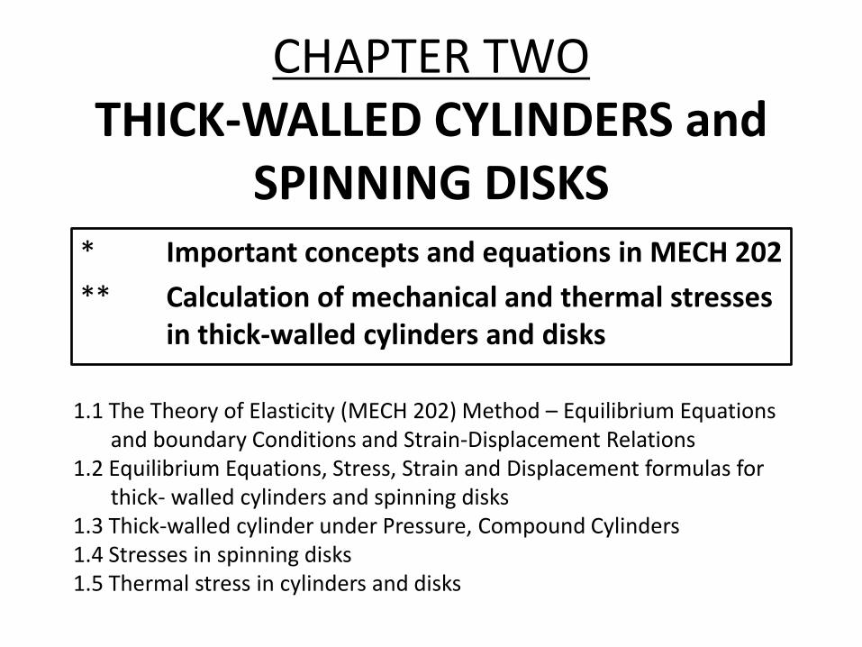
CHAPTER TWOTHICK-WALLED CYLINDERS and
SPINNING DISKS* Important concepts and equations in MECH 202
** Calculation of mechanical and thermal stresses in thick-walled cylinders and disks
1.1 The Theory of Elasticity (MECH 202) Method – Equilibrium Equations and boundary Conditions and Strain-Displacement Relations
1.2 Equilibrium Equations, Stress, Strain and Displacement formulas for thick- walled cylinders and spinning disks
1.3 Thick-walled cylinder under Pressure, Compound Cylinders1.4 Stresses in spinning disks1.5 Thermal stress in cylinders and disks

1.1 THE THEORY OF ELASTICITY (MECH 202) METHOD
• The deformation mode does not have to be described in order to solve a problem
• The solution satisfies
(1) condition of equilibrium at every point
(2) continuity of displacement field
(3) loading and support conditions (boundary condition)
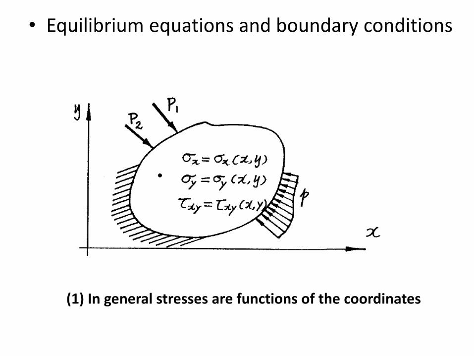
• Equilibrium equations and boundary conditions
(1) In general stresses are functions of the coordinates

• Equilibrium equations and boundary conditions
(2) Consider the equilibrium of a differential element

(3) The equilibrium of forces in X and Y directions requires (t – thickness of the element)
(4) Differential equations of equilibrium
• Equilibrium equations and boundary conditions
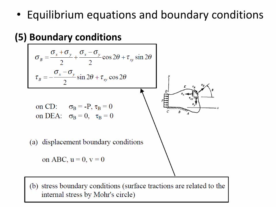
(5) Boundary conditions
• Equilibrium equations and boundary conditions
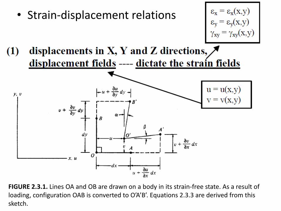
• Strain-displacement relations
FIGURE 2.3.1. Lines OA and OB are drawn on a body in its strain-free state. As a result ofloading, configuration OAB is converted to O’A’B’. Equations 2.3.3 are derived from thissketch.

(2) Normal strain
• Strain-displacement relations
(3) Shear strain

• Equations in polar coordinates


• Saint-Venant's Principle
If a system of forces acting on a small region of an elastic solid is
replaced by another force system, acting within the same region and
having the same resultant force and moment as the first system, then
stresses change appreciably only in the neighborhood of the loaded
region.

FIGURE 2.2.3. Illustration of Saint-Venant's principle. When distributed pressure loads (a) Are replaced by statically equivalent concentrated loads (b) Stresses change considerably near theloads (shaded regions), but change little elsewhere.

• Thin- and thick-walled
cylinders
1.2 EQUILIBRIUM EQUATIONS, STRESS, STRAIN AND DISPLACEMENT FORMULAS FOR THICK-WALLED CYLINDERS AND SPINNING DISKS
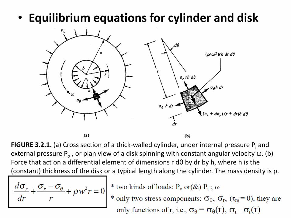
• Equilibrium equations for cylinder and disk
FIGURE 3.2.1. (a) Cross section of a thick-walled cylinder, under internal pressure Pi and external pressure Po , or plan view of a disk spinning with constant angular velocity ω. (b) Force that act on a differential element of dimensions r dθ by dr by h, where h is the (constant) thickness of the disk or a typical length along the cylinder. The mass density is ρ.
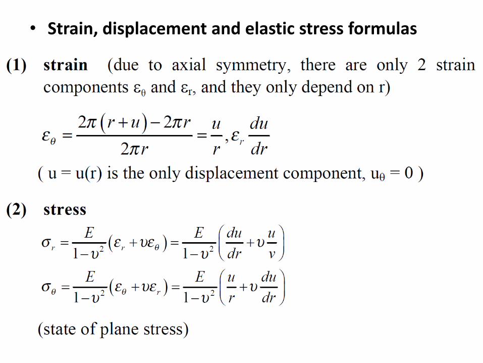
• Strain, displacement and elastic stress formulas
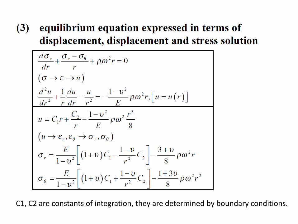
C1, C2 are constants of integration, they are determined by boundary conditions.

• Thick-walled cylinder under pressure (w = 0)
1.3 THICK-WALLED CYLINDER UNDER PRESSURE, COMPOUND CYLINDER THICK-WALLED CYLINDER
UNDER PRESSURE, COMPOUND CYLINDER
(b) stress formulas
By using above boundary conditions the constants C1
and C2 are found to be (a) Internal pressure
(b) External pressure
a = 3b
a = 3b

Finally, we have stress formulas (Lamé solution)
FIGURE 3.4.2. Stress σθ at r= b due to internal pressure only. The upper curve is the Lamé solution. The lower curve is the thinwalled equation, σθ = Pib/t. The middle curve uses the mean radius R = (a + b)/2 in place of b in the thin-walled equation.
FIGURE 3.4.3. Pressurized holes in a flat body of arbitrary contour. If holes are widely separated and not close to an edge, stresses at the holes due to pressure P are much like stresses in a very thick pressurized cylinder.

(1) If t/b < 0.1 (thin-wall), the stress solution σθ for thin-wall is almost the same as
thick-wall cylinder.
(3) In a cylinder with closed ends, axial force is provided by pressure against the end
caps, the axial stress due to internal and external pressure load is
(4) The largest shear stress is on the inside surface, at r = b,
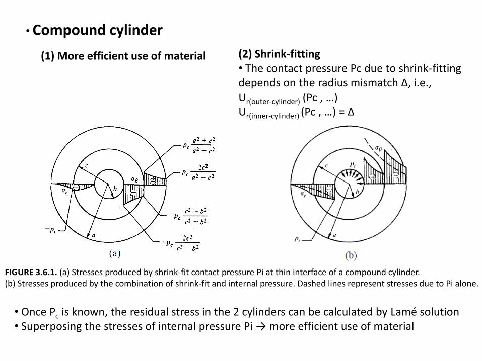
(2) Shrink-fitting• The contact pressure Pc due to shrink-fitting depends on the radius mismatch Δ, i.e.,Ur(outer-cylinder) (Pc , …)Ur(inner-cylinder) (Pc , …) = Δ
• Compound cylinder
(1) More efficient use of material
FIGURE 3.6.1. (a) Stresses produced by shrink-fit contact pressure Pi at thin interface of a compound cylinder.(b) Stresses produced by the combination of shrink-fit and internal pressure. Dashed lines represent stresses due to Pi alone.
• Once Pc is known, the residual stress in the 2 cylinders can be calculated by Lamé solution• Superposing the stresses of internal pressure Pi → more efficient use of material
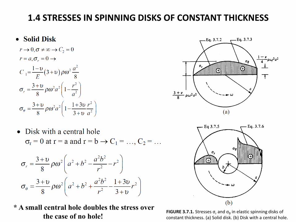
1.4 STRESSES IN SPINNING DISKS OF CONSTANT THICKNESS
FIGURE 3.7.1. Stresses σr and σθ in elastic spinning disks of constant thickness. (a) Solid disk. (b) Disk with a central hole.
* A small central hole doubles the stress over
the case of no hole!
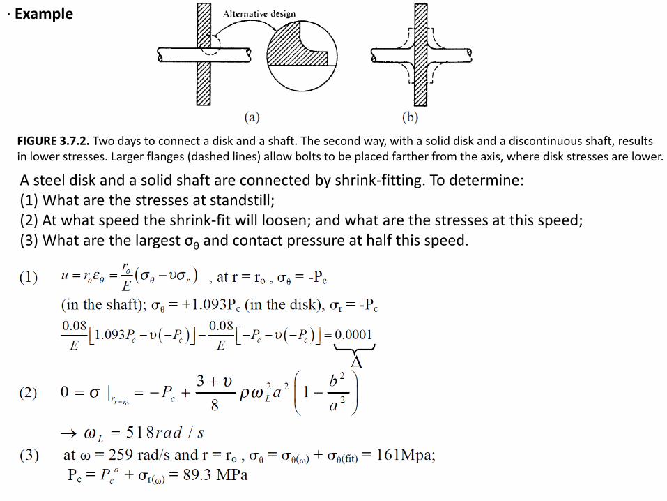
· Example
FIGURE 3.7.2. Two days to connect a disk and a shaft. The second way, with a solid disk and a discontinuous shaft, results in lower stresses. Larger flanges (dashed lines) allow bolts to be placed farther from the axis, where disk stresses are lower.
A steel disk and a solid shaft are connected by shrink-fitting. To determine:(1) What are the stresses at standstill;(2) At what speed the shrink-fit will loosen; and what are the stresses at this speed;(3) What are the largest σθ and contact pressure at half this speed.

1.5 THERMAL STRESS IN CYLINDERS AND DISKS