Embed Size (px)
Citation preview
This glossary of terms is intended to provide a brief and accu-
rate description of both conceptual and component terms used in
design, manufacturing, and tuning of R.I.T. Baja SAE Suspension
Systems. For quick referencing this chapter is divided into two sec-
tions.
The first section of the chapter focuses on theoretical concept
definitions used in describing the analysis and design of off-road
suspension system dynamics. The second segment contains compo-
nent descriptions and visual references .
Figure 1: (2005-2006)SLA A- Arm Rear Suspension
Introduction
RIT Baja SAE
Chapter Two:
Glossary of Suspension Terms
Chapter 2: Glossary of Terms
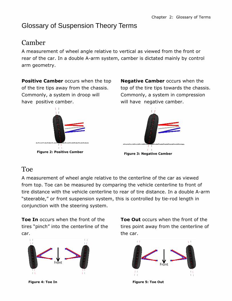
Camber A measurement of wheel angle relative to vertical as viewed from the front or
rear of the car. In a double A-arm system, camber is dictated mainly by control
arm geometry.
Glossary of Suspension Theory Terms
Positive Camber occurs when the top
of the tire tips away from the chassis.
Commonly, a system in droop will
have positive camber.
Negative Camber occurs when the
top of the tire tips towards the chassis.
Commonly, a system in compression
will have negative camber.
Toe A measurement of wheel angle relative to the centerline of the car as viewed
from top. Toe can be measured by comparing the vehicle centerline to front of
tire distance with the vehicle centerline to rear of tire distance. In a double A-arm
“steerable,” or front suspension system, this is controlled by tie-rod length in
conjunction with the steering system.
Toe In occurs when the front of the
tires “pinch” into the centerline of the
car.
Toe Out occurs when the front of the
tires point away from the centerline of
the car.
Chapter 2: Glossary of Terms
Figure 2: Positive Camber Figure 3: Negative Camber
Figure 4: Toe In Figure 5: Toe Out
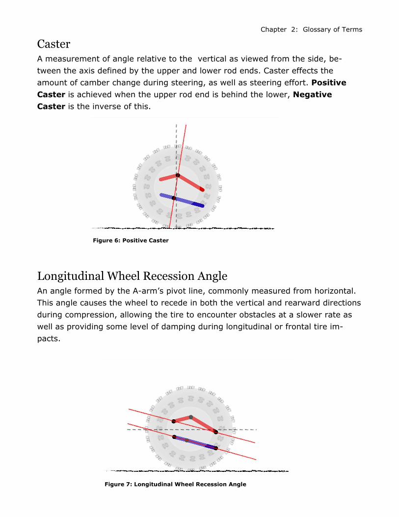
Caster A measurement of angle relative to the vertical as viewed from the side, be-
tween the axis defined by the upper and lower rod ends. Caster effects the
amount of camber change during steering, as well as steering effort. Positive
Caster is achieved when the upper rod end is behind the lower, Negative
Caster is the inverse of this.
Longitudinal Wheel Recession Angle An angle formed by the A-arm’s pivot line, commonly measured from horizontal.
This angle causes the wheel to recede in both the vertical and rearward directions
during compression, allowing the tire to encounter obstacles at a slower rate as
well as providing some level of damping during longitudinal or frontal tire im-
pacts.
Chapter 2: Glossary of Terms
Figure 6: Positive Caster
Figure 7: Longitudinal Wheel Recession Angle
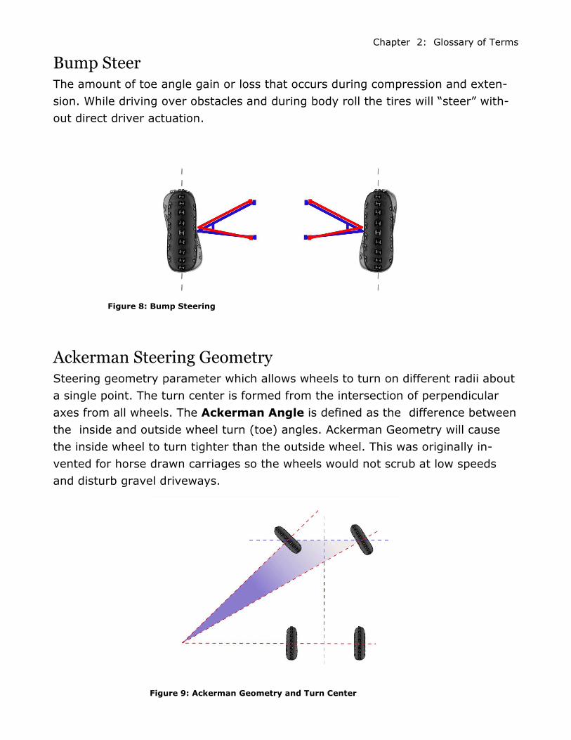
Bump Steer The amount of toe angle gain or loss that occurs during compression and exten-
sion. While driving over obstacles and during body roll the tires will “steer” with-
out direct driver actuation.
Ackerman Steering Geometry Steering geometry parameter which allows wheels to turn on different radii about
a single point. The turn center is formed from the intersection of perpendicular
axes from all wheels. The Ackerman Angle is defined as the difference between
the inside and outside wheel turn (toe) angles. Ackerman Geometry will cause
the inside wheel to turn tighter than the outside wheel. This was originally in-
vented for horse drawn carriages so the wheels would not scrub at low speeds
and disturb gravel driveways.
Chapter 2: Glossary of Terms
Figure 8: Bump Steering
Figure 9: Ackerman Geometry and Turn Center
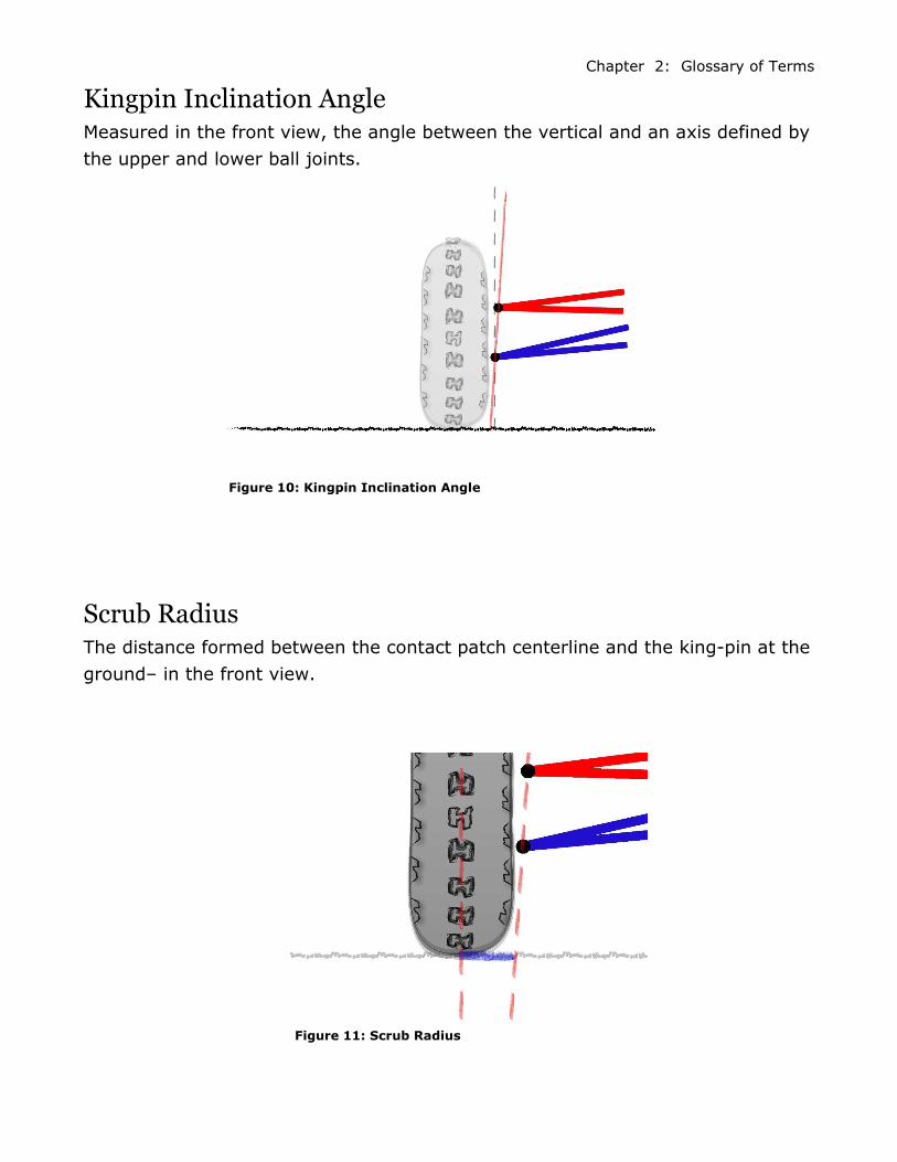
Kingpin Inclination Angle Measured in the front view, the angle between the vertical and an axis defined by
the upper and lower ball joints.
Scrub Radius The distance formed between the contact patch centerline and the king-pin at the
ground– in the front view.
Chapter 2: Glossary of Terms
Figure 10: Kingpin Inclination Angle
Figure 11: Scrub Radius
Progressive Wheel Rate The geometry of the suspension linking components, including the shock and
springs, used to create an increasing wheel rate (stiffness) during compression.
Wheel Rate Is the effective spring rate of the suspension when force is applied at the wheel.
This parameter is calculated from the spring rate through geometry of the sus-
pension out to the wheel.
Spring Rate A measure of the stiffness of a spring defined as the pounds force per inch of
spring displacement.
Body Roll The tilt of the body relative to the suspension. This is encountered during turning
where centripetal force will cause the chassis to lean to the outside of the turn,
causing the outside suspension to compress and the inside to extend.
Roll Rate A measurement of the chassis’s stiffness during roll. Defined as foot pounds per
Contact Patch The contact patch is the area of contact between the ground and the tire. This
parameter changes with many factors including tire pressure and wheel loads.
Chapter 2: Glossary of Terms
Jounce Travel Compression movement of suspension. Also can be termed as the amount of
available suspension travel in compression from ride height.
Droop Travel Extension travel of the suspension. Also can be termed as the amount of available
suspension travel in extension from ride height.
Ride Height The static default position of the suspension system. Also can be termed as the
height at which the car sits with driver weight with no external forces.
Chapter 2: Glossary of Terms
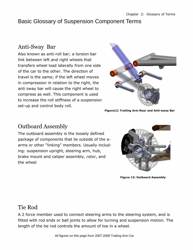
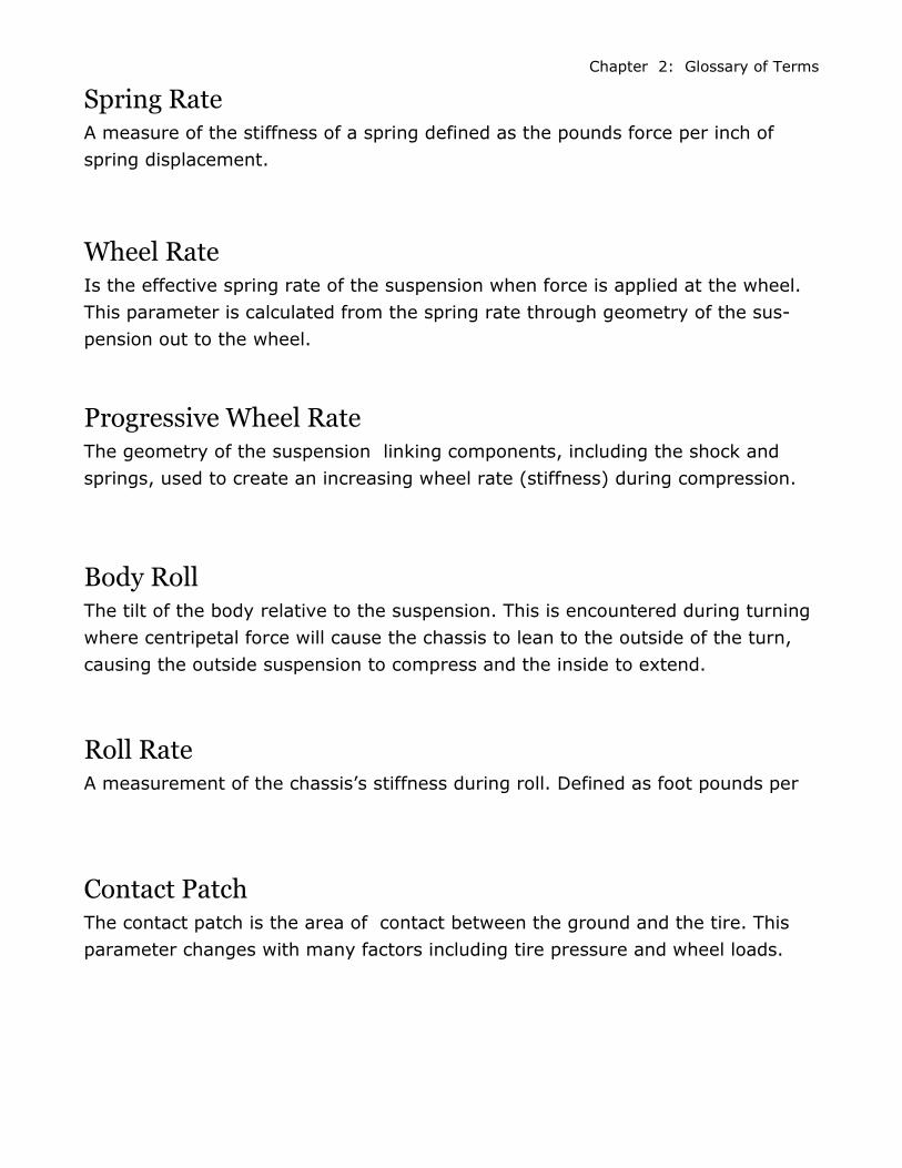
Anti-Sway Bar Also known as anti-roll bar; a torsion bar
link between left and right wheels that
transfers wheel load laterally from one side
of the car to the other. The direction of
travel is the same; if the left wheel moves
in compression in relation to the right, the
anti sway bar will cause the right wheel to
compress as well. This component is used
to increase the roll stiffness of a suspension
set-up and control body roll.
Tie Rod A 2 force member used to connect steering arms to the steering system, and is
fitted with rod ends or ball joints to allow for turning and suspension motion. The
length of the tie rod controls the amount of toe in a wheel.
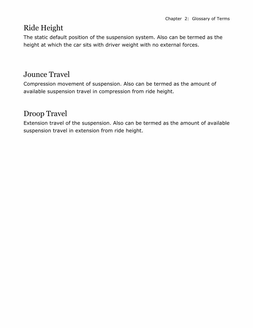
Outboard Assembly The outboard assembly is the loosely defined
package of components that lie outside of the a-
arms or other “linking” members. Usually includ-
ing: suspension upright, steering arm, hub,
brake mount and caliper assembly, rotor, and
the wheel
Basic Glossary of Suspension Component Terms Chapter 2: Glossary of Terms
All figures on this page from 2007-2008 Trailing Arm Car
Figure 13: Outboard Assembly
Figure12: Trailing Arm Rear and Anti-sway Bar

Upright Mounted vertically (upright) between the upper and
lower control arm’s outer rod ends. The upright is the
foundation of all outboard systems: the spindle and
calipers are mounted directly to it.
Steering Arm The steering arm provides the third point (defining a
plane) for linking to and controlling the outboard assem-
bly. It is the primary input of steering force to the upright
and outboard assembly.
Spindle The shaft extending from the upright about which the
wheel and hub rotate.
All figures on this page from 2007-2008 Trailing Arm Car
Chapter 2: Glossary of Terms
Figure 14: Upright
Figure 15 : Steering Arm
and Upright
Figure 16: Spindle, Steering
Arm, and Upright Assembly

Hub The component that interfaces the rotating
wheel and the stationary spindle. Wheel bear-
ings are housed by this component.
Steering Rack The assembly that controls the steering of the car by converting the rotational
motion of the steering wheel into linear motion of the front tie-rods. It is titled for
its rack and pinion gear design.
Chapter 2: Glossary of Terms
Figure 17: Positive Camber
Figure 18: 2008-2009 Steering Rack
Figure 19: 2007-2008 Steering Rack