Embed Size (px)
Citation preview

Chapter 9
Covalent Bonding:
Orbitals
Copyright ©2018 Cengage Learning. All Rights Reserved.

Chapter 9Table of Contents
Copyright ©2018 Cengage Learning. All Rights Reserved.
▪ (9.1) Hybridization and the localized electron model
▪ (9.2) The molecular orbital model
▪ (9.3) Bonding in homonuclear diatomic molecules
▪ (9.4) Bonding in heteronuclear diatomic molecules
▪ (9.5) Combining the localized electron and molecular orbital models
Section 9.1Hybridization and the Localized Electron Model
Copyright ©2018 Cengage Learning. All Rights Reserved.
Hybridization
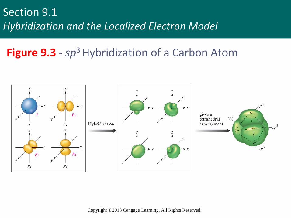
▪ Mixing of native atomic orbitals to form special orbitals for bonding
▪ sp3 orbitals - Formed from one 2s and three 2porbitals
▪ Atoms that undergo this process are said to be sp3
hybridized
Section 9.1Hybridization and the Localized Electron Model
Copyright ©2018 Cengage Learning. All Rights Reserved.
Figure 9.3 - sp3 Hybridization of a Carbon Atom
Section 9.1Hybridization and the Localized Electron Model
Copyright ©2018 Cengage Learning. All Rights Reserved.
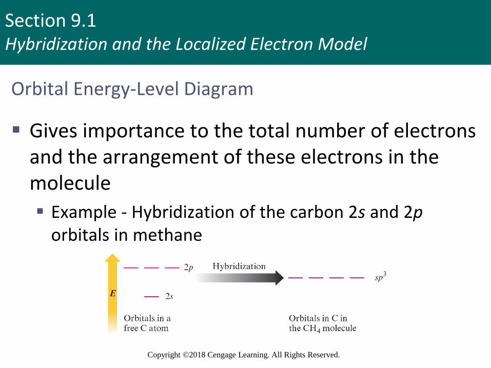
Orbital Energy-Level Diagram
▪ Gives importance to the total number of electrons and the arrangement of these electrons in the molecule
▪ Example - Hybridization of the carbon 2s and 2porbitals in methane
Section 9.1Hybridization and the Localized Electron Model
Copyright ©2018 Cengage Learning. All Rights Reserved.
Key Principle in sp3 Hybridization
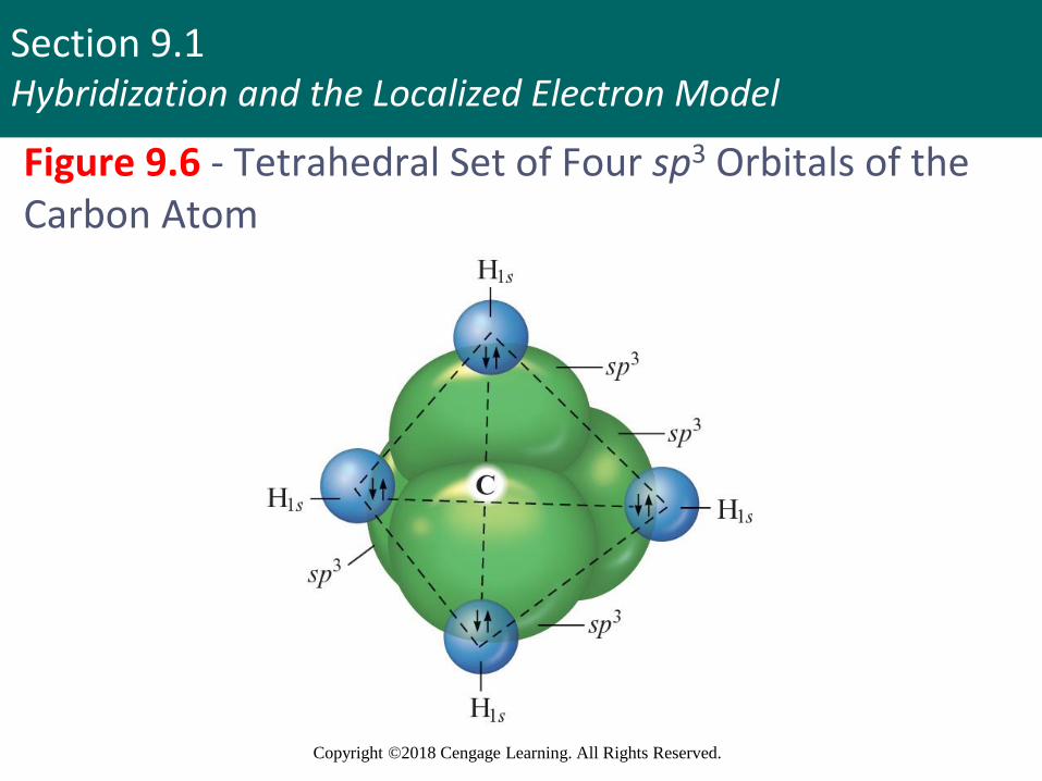
▪ Whenever an atom requires a set of equivalent tetrahedral atomic orbitals, this model assumes that the atom adopts a set of sp3 orbitals
▪ The atom undergoes sp3 hybridization
6
Section 9.1Hybridization and the Localized Electron Model
Copyright ©2018 Cengage Learning. All Rights Reserved.
Figure 9.6 - Tetrahedral Set of Four sp3 Orbitals of the Carbon Atom
Section 9.1Hybridization and the Localized Electron Model
Copyright ©2018 Cengage Learning. All Rights Reserved.
Critical Thinking
▪ What if the sp3 hybrid orbitals were higher in energy than the p orbitals in the free atom?
▪ How would this affect our model of bonding?
8
Section 9.1Hybridization and the Localized Electron Model
Copyright ©2018 Cengage Learning. All Rights Reserved.
Example 9.1 - The Localized Electron Model I
▪ Describe the bonding in the ammonia molecule using the localized electron model
Section 9.1Hybridization and the Localized Electron Model
Copyright ©2018 Cengage Learning. All Rights Reserved.
Example 9.1 - Solution
▪ A complete description of the bonding involves three steps
▪ Writing the Lewis structure
▪ Determining the arrangement of electron pairs using the VSEPR model
▪ Determining the hybrid atomic orbitals needed to describe the bonding in the molecule
Section 9.1Hybridization and the Localized Electron Model
Copyright ©2018 Cengage Learning. All Rights Reserved.
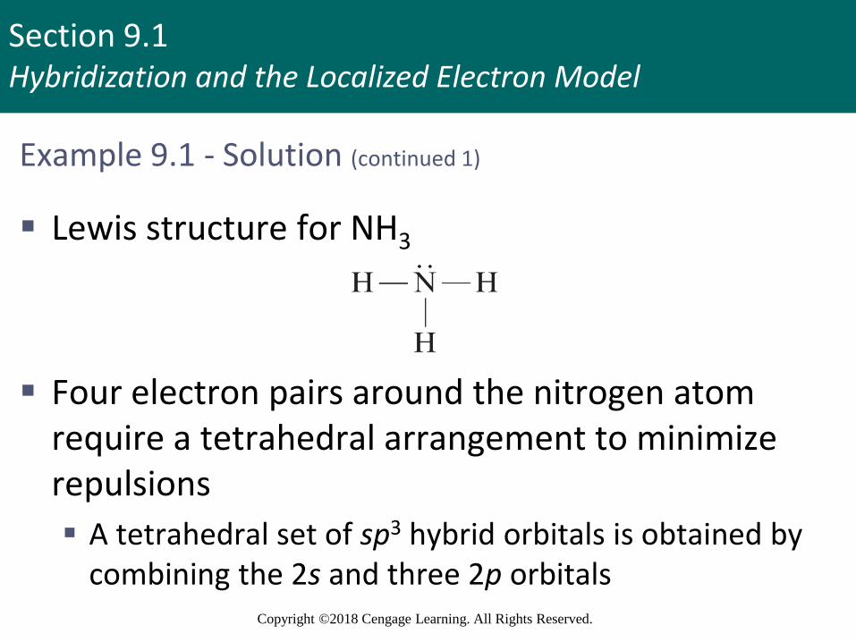
Example 9.1 - Solution (continued 1)
▪ Lewis structure for NH3
▪ Four electron pairs around the nitrogen atom require a tetrahedral arrangement to minimize repulsions
▪ A tetrahedral set of sp3 hybrid orbitals is obtained by combining the 2s and three 2p orbitals
Section 9.1Hybridization and the Localized Electron Model
Copyright ©2018 Cengage Learning. All Rights Reserved.
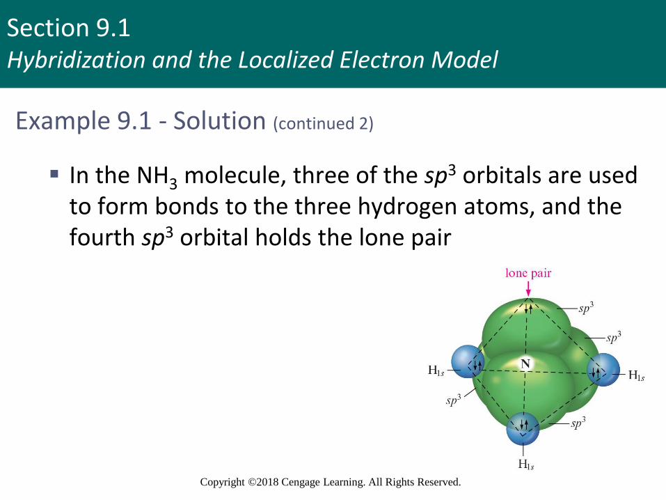
Example 9.1 - Solution (continued 2)
▪ In the NH3 molecule, three of the sp3 orbitals are used to form bonds to the three hydrogen atoms, and the fourth sp3 orbital holds the lone pair
Section 9.1Hybridization and the Localized Electron Model
Copyright ©2018 Cengage Learning. All Rights Reserved.
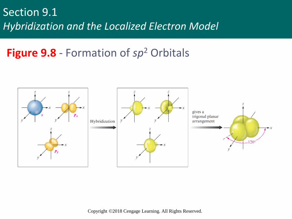
sp2 Hybridization
▪ Combination of one 2s and two 2p orbitals
▪ Gives a trigonal planar arrangement of atomic orbitals
▪ Bond angles - 120 degrees
▪ One 2p orbital is not used
▪ Remaining p orbital (pz) is oriented perpendicular to the plane of the sp2 orbitals
13
Section 9.1Hybridization and the Localized Electron Model
Copyright ©2018 Cengage Learning. All Rights Reserved.
Figure 9.8 - Formation of sp2 Orbitals

Section 9.1Hybridization and the Localized Electron Model
Copyright ©2018 Cengage Learning. All Rights Reserved.
Figure 9.9 - Orbital Energy-Level Diagram for sp2
Hybridization
Section 9.1Hybridization and the Localized Electron Model
Copyright ©2018 Cengage Learning. All Rights Reserved.
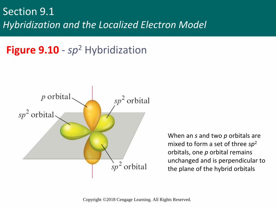
Figure 9.10 - sp2 Hybridization
When an s and two p orbitals are mixed to form a set of three sp2
orbitals, one p orbital remains unchanged and is perpendicular to the plane of the hybrid orbitals

Section 9.1Hybridization and the Localized Electron Model
Copyright ©2018 Cengage Learning. All Rights Reserved.
Types of sp2 Hybridized Bonds
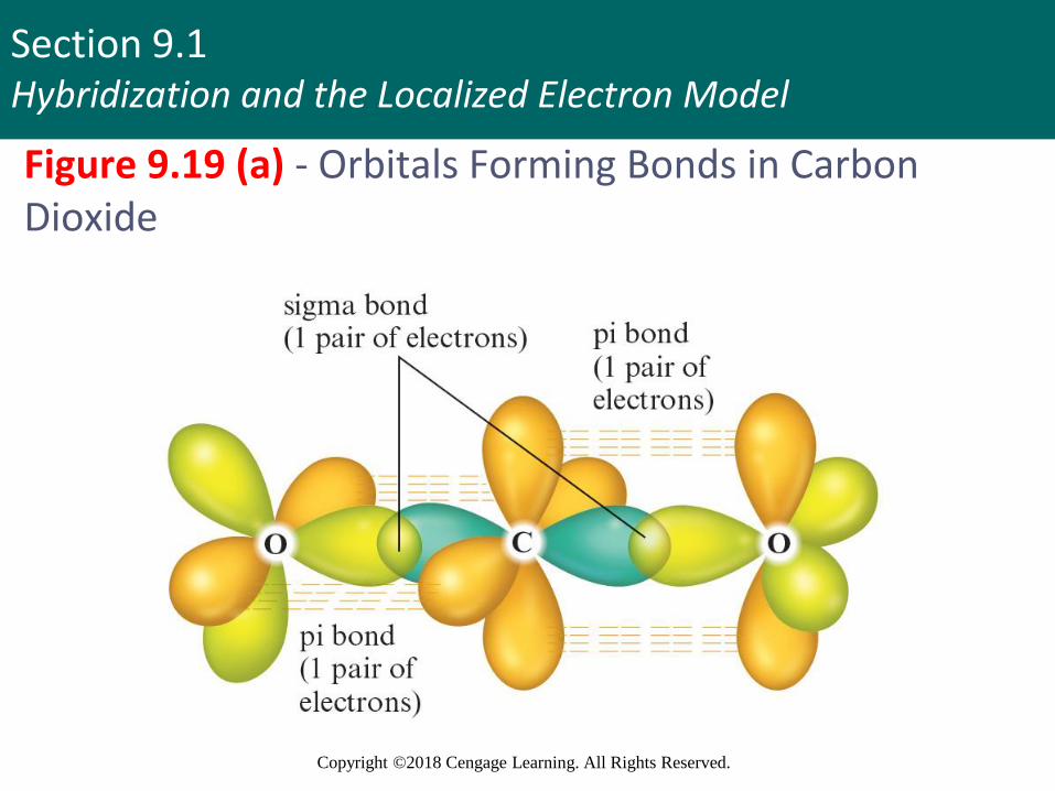
▪ Sigma () bond: Electron pair is shared in an area centered on a line running between the atoms
▪ Pi () bond: Parallel p orbitals share an electron pair, which occupies the space above and below a line joining the atoms
▪ A double bond always consists of one bond and one bond
17
Section 9.1Hybridization and the Localized Electron Model
Copyright ©2018 Cengage Learning. All Rights Reserved.
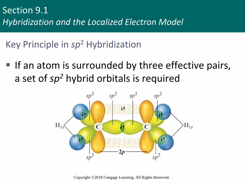
Key Principle in sp2 Hybridization
▪ If an atom is surrounded by three effective pairs, a set of sp2 hybrid orbitals is required
Section 9.1Hybridization and the Localized Electron Model
Copyright ©2018 Cengage Learning. All Rights Reserved.
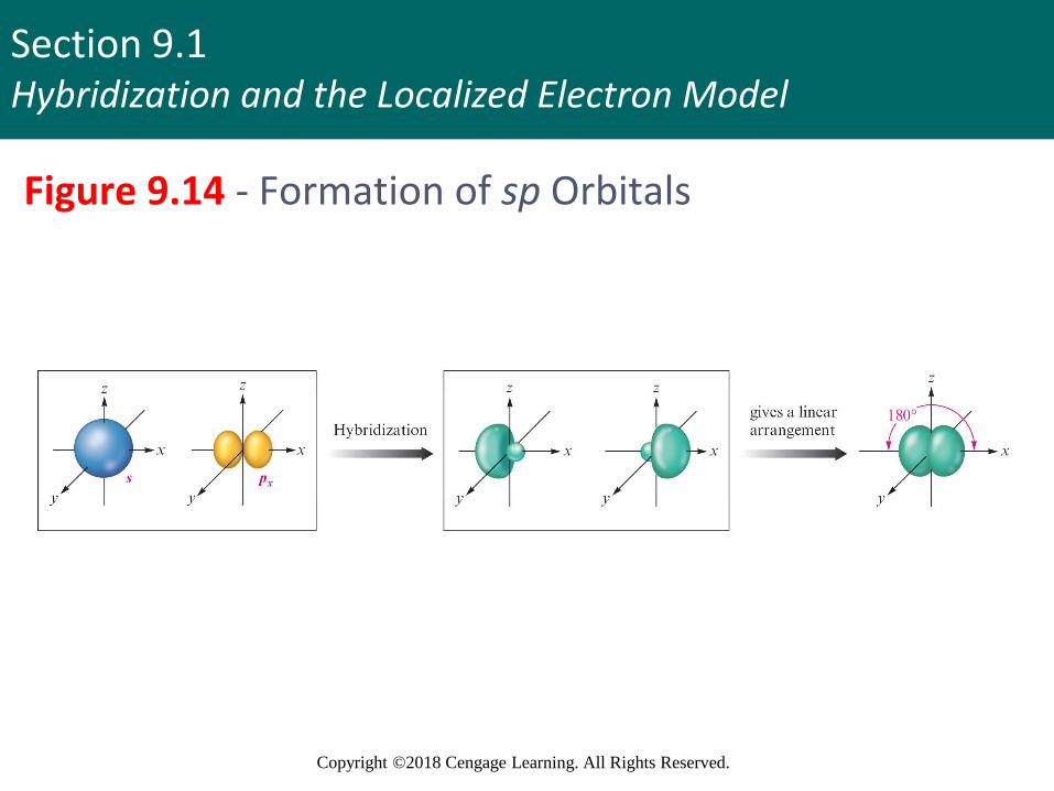
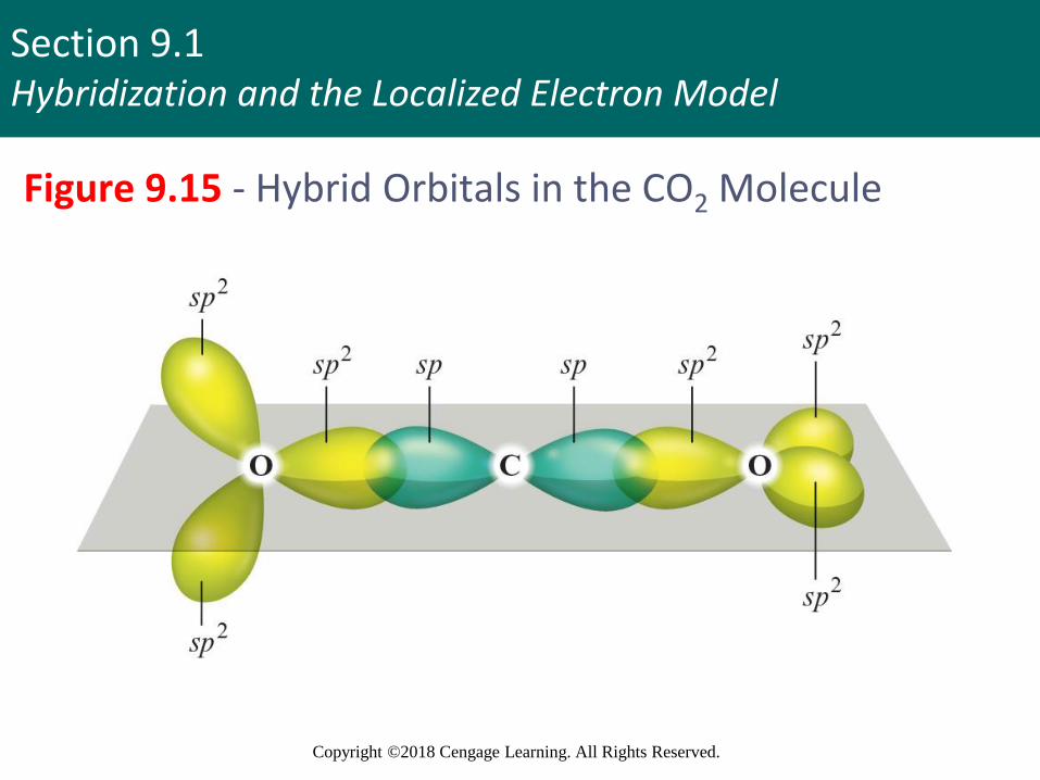
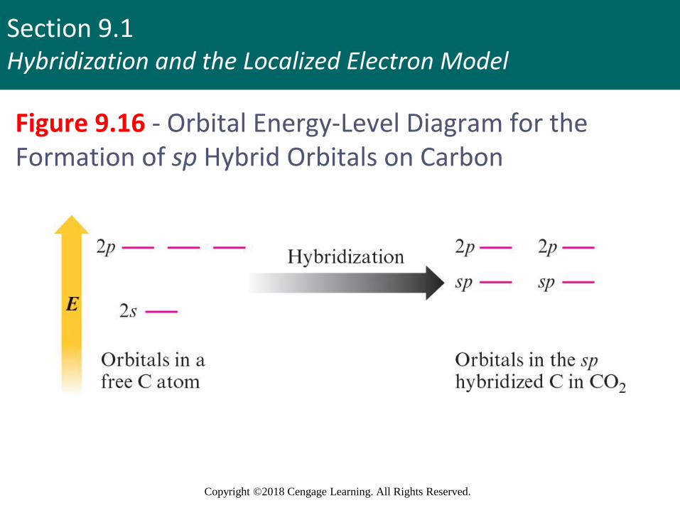
sp Hybridization
▪ Involves one s and one p orbital
▪ Two effective pairs around an atom will always require sp hybridization of that atom
▪ Example - Carbon atoms in carbon dioxide
▪ Two 2p orbitals are unaffected
▪ Used in formation of π bonds with oxygen atoms
19
Section 9.1Hybridization and the Localized Electron Model
Copyright ©2018 Cengage Learning. All Rights Reserved.
Figure 9.14 - Formation of sp Orbitals
Section 9.1Hybridization and the Localized Electron Model
Copyright ©2018 Cengage Learning. All Rights Reserved.
Figure 9.15 - Hybrid Orbitals in the CO2 Molecule
Section 9.1Hybridization and the Localized Electron Model
Copyright ©2018 Cengage Learning. All Rights Reserved.
Figure 9.16 - Orbital Energy-Level Diagram for the Formation of sp Hybrid Orbitals on Carbon

Section 9.1Hybridization and the Localized Electron Model
Copyright ©2018 Cengage Learning. All Rights Reserved.
Figure 9.17 - Orbitals of an sp Hybridized Carbon Atom
Section 9.1Hybridization and the Localized Electron Model
Copyright ©2018 Cengage Learning. All Rights Reserved.
Figure 9.19 (a) - Orbitals Forming Bonds in Carbon Dioxide
Section 9.1Hybridization and the Localized Electron Model
Copyright ©2018 Cengage Learning. All Rights Reserved.
Example 9.2 - The Localized Electron Model II
▪ Describe the bonding in the N2 molecule
Section 9.1Hybridization and the Localized Electron Model
Copyright ©2018 Cengage Learning. All Rights Reserved.
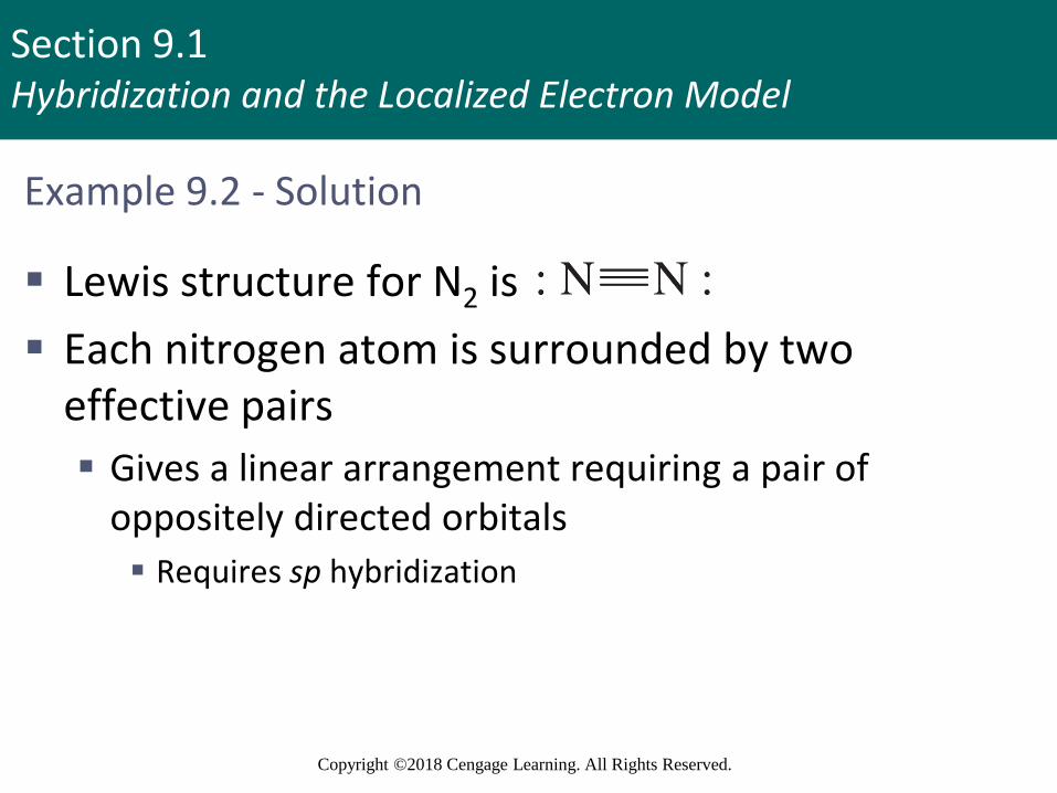
Example 9.2 - Solution
▪ Lewis structure for N2 is
▪ Each nitrogen atom is surrounded by two effective pairs
▪ Gives a linear arrangement requiring a pair of oppositely directed orbitals
▪ Requires sp hybridization

Section 9.1Hybridization and the Localized Electron Model
Copyright ©2018 Cengage Learning. All Rights Reserved.
Example 9.2 - Solution (continued 1)
▪ Each nitrogen atom has two sp hybrid orbitals and two unchanged p orbitals▪ sp orbitals form the bond between the nitrogen
atoms and hold lone pairs
▪ p orbitals form the two bonds
▪ Each pair of overlapping parallel p orbitals holds one electron pair▪ Accounts for electron arrangement given in the Lewis
structure

Section 9.1Hybridization and the Localized Electron Model
Copyright ©2018 Cengage Learning. All Rights Reserved.
Example 9.2 - Solution (continued 2)
▪ Triple bond consists of a bond and two bonds
▪ A lone pair occupies an sp orbital on each nitrogen atom
Section 9.1Hybridization and the Localized Electron Model
Copyright ©2018 Cengage Learning. All Rights Reserved.
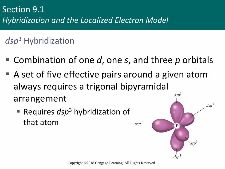
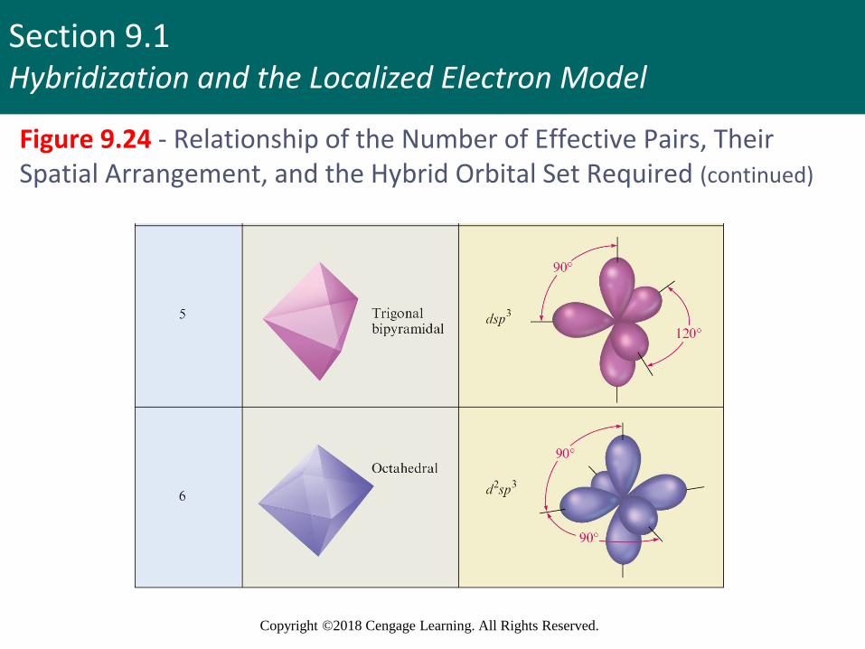
dsp3 Hybridization
▪ Combination of one d, one s, and three p orbitals
▪ A set of five effective pairs around a given atom always requires a trigonal bipyramidal arrangement
▪ Requires dsp3 hybridization of that atom

Section 9.1Hybridization and the Localized Electron Model
Copyright ©2018 Cengage Learning. All Rights Reserved.
dsp3 Hybridization (continued)
▪ Each chlorine atom in PCl5 is surrounded by four electron pairs
▪ Requires a tetrahedral arrangement
▪ Each chlorine atom requires a set of four sp3 orbitals

Section 9.1Hybridization and the Localized Electron Model
Copyright ©2018 Cengage Learning. All Rights Reserved.
Example 9.3 - The Localized Electron Model III
▪ Describe the bonding in the triiodide ion (I3–)

Section 9.1Hybridization and the Localized Electron Model
Copyright ©2018 Cengage Learning. All Rights Reserved.
Example 9.3 - Solution
▪ The Lewis structure for I3–
▪ The central iodine atom has five pairs of electrons▪ Requires a trigonal bipyramidal arrangement, which in turn
requires a set of dsp3 orbitals
▪ Outer iodine atoms have four pairs of electrons
▪ Requires tetrahedral arrangement and sp3 hybridization
Section 9.1Hybridization and the Localized Electron Model
Copyright ©2018 Cengage Learning. All Rights Reserved.
Example 9.3 - Solution (continued)
▪ The central iodine atom is dsp3 hybridized
▪ Three hybrid orbitals hold lone pairs
▪ Two hybrid orbitals overlap with sp3 orbitals of the other two iodine atoms to form bonds

Section 9.1Hybridization and the Localized Electron Model
Copyright ©2018 Cengage Learning. All Rights Reserved.
d2sp3 Hybridization
▪ Combination of two d, one s, and three p orbitals
▪ Requires an octahedral arrangement of six hybrid orbitals
▪ Six electron pairs around an atom are always arranged octahedrally
▪ Require d2sp3 hybridization of the atom

Section 9.1Hybridization and the Localized Electron Model
Copyright ©2018 Cengage Learning. All Rights Reserved.
Figure 9.23 - An Octahedral Set of d2sp3 Orbitals on a Sulfur Atom

Section 9.1Hybridization and the Localized Electron Model
Copyright ©2018 Cengage Learning. All Rights Reserved.
Interactive Example 9.4 - The Localized Electron Model IV
▪ How is the xenon atom in XeF4 hybridized?
Section 9.1Hybridization and the Localized Electron Model
Copyright ©2018 Cengage Learning. All Rights Reserved.
Interactive Example 9.4 - Solution
▪ XeF4 has six pairs of electrons around xenon that are arranged octahedrally to minimize repulsions
▪ An octahedral set of six atomic orbitals is required to hold these electrons, and the xenon atom is d2sp3
hybridized

Section 9.1Hybridization and the Localized Electron Model
Copyright ©2018 Cengage Learning. All Rights Reserved.
Interactive Example 9.4 - Solution (continued)
Section 9.1Hybridization and the Localized Electron Model
Copyright ©2018 Cengage Learning. All Rights Reserved.
Problem Solving Strategy - Using the Localized Electron Model
▪ Draw the Lewis structure(s)
▪ Determine the arrangement of electron pairs using the VSEPR model
▪ Specify the hybrid orbitals required to accommodate the electron pairs

Section 9.1Hybridization and the Localized Electron Model
Copyright ©2018 Cengage Learning. All Rights Reserved.
Figure 9.24 - Relationship of the Number of Effective Pairs, Their Spatial Arrangement, and the Hybrid Orbital Set Required
Section 9.1Hybridization and the Localized Electron Model
Copyright ©2018 Cengage Learning. All Rights Reserved.
Figure 9.24 - Relationship of the Number of Effective Pairs, Their Spatial Arrangement, and the Hybrid Orbital Set Required (continued)
Section 9.1Hybridization and the Localized Electron Model
Copyright ©2018 Cengage Learning. All Rights Reserved.
Interactive Example 9.5 - The Localized Electron Model V
▪ For each of the following molecules or ions, predict the hybridization of each atom, and describe the molecular structure
a. CO
b. BF4–
c. XeF2
Section 9.1Hybridization and the Localized Electron Model
Copyright ©2018 Cengage Learning. All Rights Reserved.
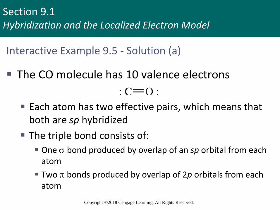
Interactive Example 9.5 - Solution (a)
▪ The CO molecule has 10 valence electrons
▪ Each atom has two effective pairs, which means that both are sp hybridized
▪ The triple bond consists of:
▪ One bond produced by overlap of an sp orbital from each atom
▪ Two bonds produced by overlap of 2p orbitals from each atom

Section 9.1Hybridization and the Localized Electron Model
Copyright ©2018 Cengage Learning. All Rights Reserved.
Interactive Example 9.5 - Solution (a) (continued)
▪ The lone pairs are in sp orbitals
▪ The molecule exhibits a linear arrangement of atoms since it has only two atoms
Section 9.1Hybridization and the Localized Electron Model
Copyright ©2018 Cengage Learning. All Rights Reserved.
Interactive Example 9.5 - Solution (b)
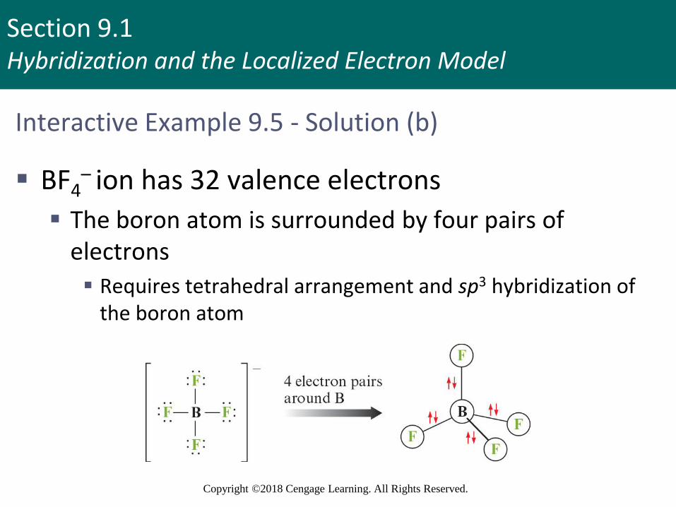
▪ BF4– ion has 32 valence electrons
▪ The boron atom is surrounded by four pairs of electrons
▪ Requires tetrahedral arrangement and sp3 hybridization of the boron atom

Section 9.1Hybridization and the Localized Electron Model
Copyright ©2018 Cengage Learning. All Rights Reserved.
Interactive Example 9.5 - Solution (b) (continued)
▪ Each fluorine atom has four electron pairs
▪ Assumed to be sp3 hybridized
▪ Molecular structure - Tetrahedral

Section 9.1Hybridization and the Localized Electron Model
Copyright ©2018 Cengage Learning. All Rights Reserved.
Interactive Example 9.5 - Solution (c)
▪ XeF2 has 22 valence electrons
▪ The xenon atom is surrounded by five electron pairs
▪ Requires a trigonal bipyramidal arrangement
Section 9.1Hybridization and the Localized Electron Model
Copyright ©2018 Cengage Learning. All Rights Reserved.
Interactive Example 9.5 - Solution (c) (continued)
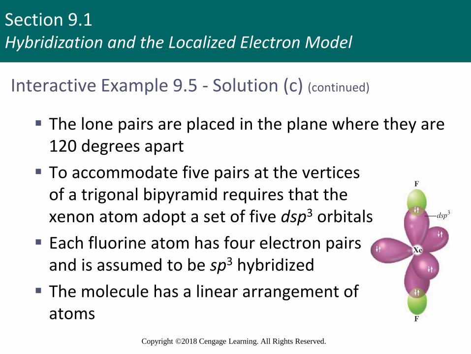
▪ The lone pairs are placed in the plane where they are 120 degrees apart
▪ To accommodate five pairs at the verticesof a trigonal bipyramid requires that thexenon atom adopt a set of five dsp3 orbitals
▪ Each fluorine atom has four electron pairsand is assumed to be sp3 hybridized
▪ The molecule has a linear arrangement ofatoms
Section 9.1Hybridization and the Localized Electron Model
Copyright ©2018 Cengage Learning. All Rights Reserved.
Join In (1)
▪ Which of the following molecules contains a nitrogen atom that is sp2 hybridized?
a. NH3
b. NO3–
c. N2
d. HCN

Section 9.1Hybridization and the Localized Electron Model
Copyright ©2018 Cengage Learning. All Rights Reserved.
Join In (2)
▪ What is the hybridization of Cl in the molecule ClF3?
a. sp
b. sp2
c. sp3
d. dsp3
e. d2sp3
Section 9.1Hybridization and the Localized Electron Model
Copyright ©2018 Cengage Learning. All Rights Reserved.
Join In (3)
▪ Atoms that obey the octet rule and that are sp3
hybridized form _____ bond(s)
a. 0
b. 1
c. 2
d. 3
e. 4

Section 9.1Hybridization and the Localized Electron Model
Copyright ©2018 Cengage Learning. All Rights Reserved.
Join In (4)
▪ What is the hybridization of the central atom in ICl4
–?
a. sp
b. sp2
c. sp3
d. dsp3
e. d2sp3
Section 9.1Hybridization and the Localized Electron Model
Copyright ©2018 Cengage Learning. All Rights Reserved.
Join In (5)
▪ Which of the following has two bonds?
a. C2H6
b. C2H4
c. C2H2
d. C3H8
e. CH4
Section 9.1Hybridization and the Localized Electron Model
Copyright ©2018 Cengage Learning. All Rights Reserved.
Join In (6)
▪ Which of the following statements is true?
a. A triple bond is composed of two bonds and one bond
b. bonds result from the head-to-head overlap of atomic orbitals
c. Free rotation may occur about a double bond
d. bonds have electron density on the internuclear axis

Section 9.1Hybridization and the Localized Electron Model
Copyright ©2018 Cengage Learning. All Rights Reserved.
Join In (7)
▪ Which of the following has the shortest N–O bond?
a. NO3−
b. NO+
c. NO2−

Section 9.1Hybridization and the Localized Electron Model
Copyright ©2018 Cengage Learning. All Rights Reserved.
Join In (8)
▪ Which of the following statements about the CO3
2- ion is false?
a. The orbitals on the carbon atom are sp2 hybridized
b. One C–O bond is shorter than the other
c. The ion has a total of 24 valence electrons

Section 9.2The Molecular Orbital Model
Copyright ©2018 Cengage Learning. All Rights Reserved.
Limitations of the Localized Electron Model
▪ Incorrectly assumes that electrons are localized
▪ Concept of resonance must be added
▪ Does not deal effectively with molecules containing unpaired electrons
▪ Does not provide direct information about bond energies
Copyright © Cengage Learning. All rights reserved 57
Section 9.2The Molecular Orbital Model
Copyright ©2018 Cengage Learning. All Rights Reserved.
Molecular Orbitals (MOs)
▪ Have the same characteristics as atomic orbitals
▪ Can hold two electrons with opposite spins
▪ Square of the molecular orbital wave function indicates electron probability
Section 9.2The Molecular Orbital Model
Copyright ©2018 Cengage Learning. All Rights Reserved.
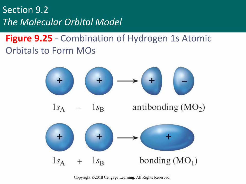
Figure 9.25 - Combination of Hydrogen 1s Atomic Orbitals to Form MOs

Section 9.2The Molecular Orbital Model
Copyright ©2018 Cengage Learning. All Rights Reserved.
Properties of Molecular Orbitals of Hydrogen
▪ Electron probability of both molecular orbitals is centered along the line passing through the two nuclei
▪ MO1 and MO2 are referred to as sigma (σ) molecular orbitals
▪ In the molecule, only themolecular orbitals areavailable for occupationby electrons
Section 9.2The Molecular Orbital Model
Copyright ©2018 Cengage Learning. All Rights Reserved.
Properties of Molecular Orbitals (continued 1)
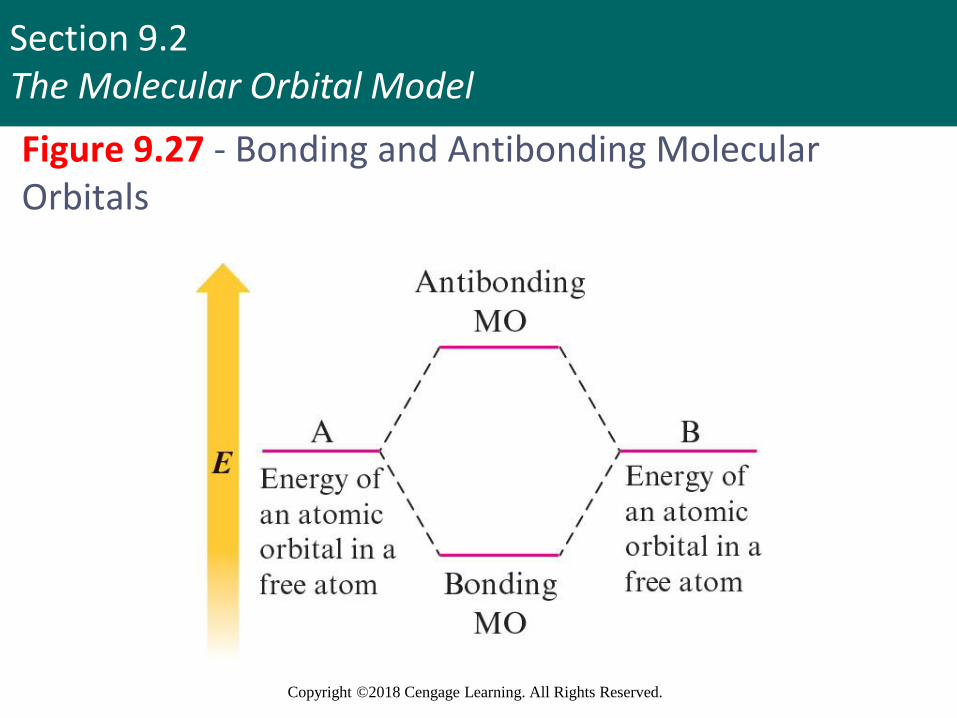
▪ Bonding and antibonding
▪ Bonding molecular orbital: Lower in energy than the atomic orbitals of which it is composed
▪ Electrons in this orbital will favor bonding
▪ Antibonding molecular orbital: Higher in energy than the atomic orbitals of which it is composed
▪ Electrons in this orbital will favor the separated atoms
Copyright © Cengage Learning. All rights reserved 61
Section 9.2The Molecular Orbital Model
Copyright ©2018 Cengage Learning. All Rights Reserved.
Figure 9.27 - Bonding and Antibonding Molecular Orbitals
Section 9.2The Molecular Orbital Model
Copyright ©2018 Cengage Learning. All Rights Reserved.
Properties of Molecular Orbitals (continued 2)
▪ MO model is physically reasonable ▪ There is high probability of finding electrons between
nuclei in bonding MOs
▪ Electrons are outside the space between the nuclei in antibonding MOs
▪ Labels on molecular orbitals indicate their shape, the parent atomic orbitals, and whether they are bonding or antibonding▪ Antibonding character is indicated by an asterisk
Section 9.2The Molecular Orbital Model
Copyright ©2018 Cengage Learning. All Rights Reserved.
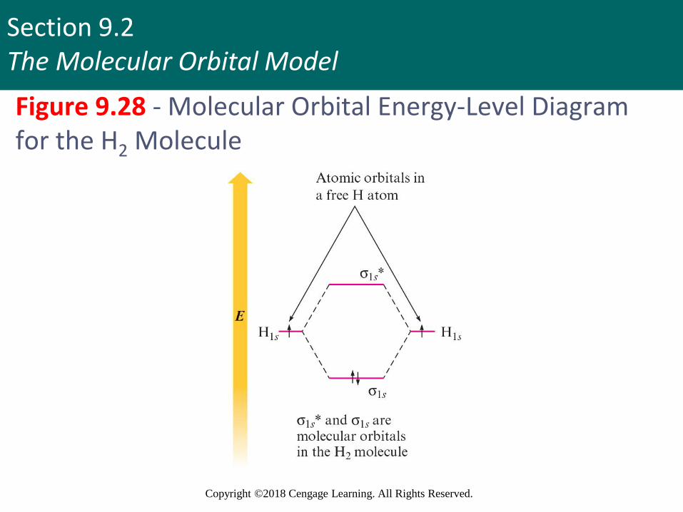
Properties of Molecular Orbitals (continued 3)
▪ Molecular electronic configuration can be written in the same way as atomic configurations
▪ Each molecular orbital can hold two electrons
▪ Spins should be opposite
▪ Molecular orbitals are conserved
▪ Number of MOs will be same as the number of atomic orbitals used to construct them
Section 9.2The Molecular Orbital Model
Copyright ©2018 Cengage Learning. All Rights Reserved.
Figure 9.28 - Molecular Orbital Energy-Level Diagram for the H2 Molecule
Section 9.2The Molecular Orbital Model
Copyright ©2018 Cengage Learning. All Rights Reserved.
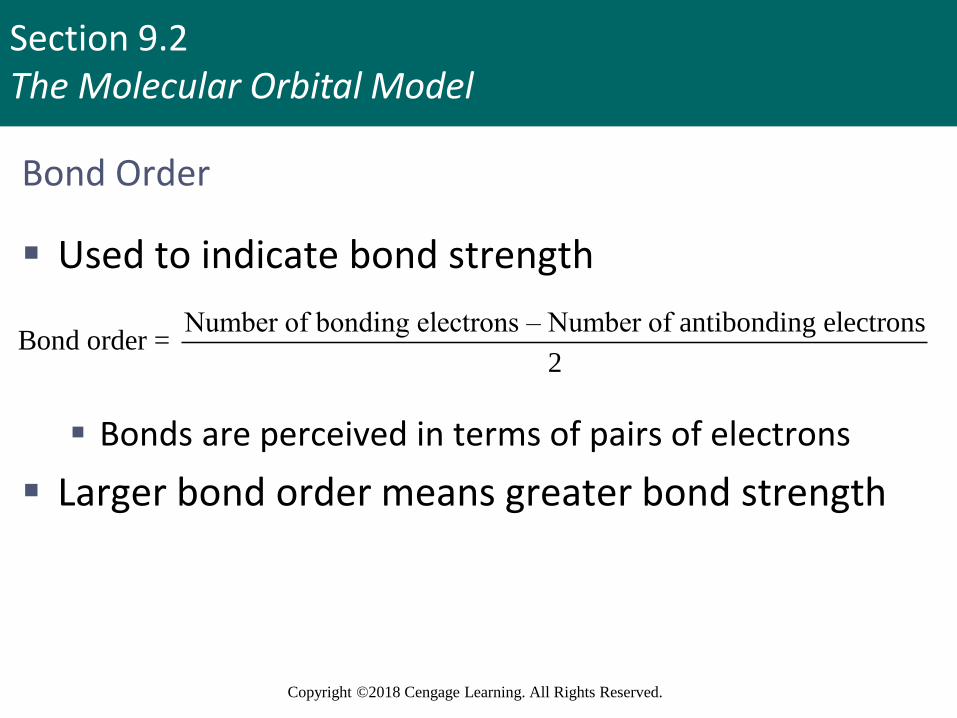
Bond Order
▪ Used to indicate bond strength
▪ Bonds are perceived in terms of pairs of electrons
▪ Larger bond order means greater bond strength
Number of bonding electrons – Number of antibonding electronsBond order =
2
Section 9.2The Molecular Orbital Model
Copyright ©2018 Cengage Learning. All Rights Reserved.
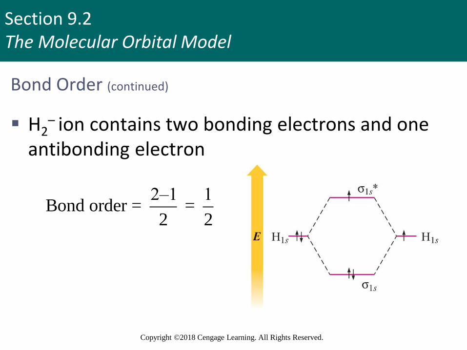
Bond Order (continued)
▪ H2– ion contains two bonding electrons and one
antibonding electron
2–1 1Bond order = =
2 2
Section 9.3Bonding in Homonuclear Diatomic Molecules
Copyright ©2018 Cengage Learning. All Rights Reserved.
Homonuclear Diatomic Molecules
▪ Composed of two identical atoms
▪ Only the valence orbitals of the atoms contribute significantly to the molecular orbitals of a particular molecule
Copyright © Cengage Learning. All rights reserved 68
Section 9.3Bonding in Homonuclear Diatomic Molecules
Copyright ©2018 Cengage Learning. All Rights Reserved.
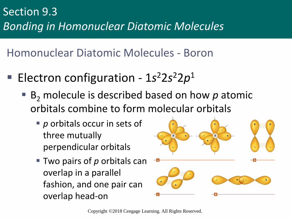
Homonuclear Diatomic Molecules - Boron
▪ Electron configuration - 1s22s22p1
▪ B2 molecule is described based on how p atomic orbitals combine to form molecular orbitals
▪ p orbitals occur in sets of three mutually perpendicular orbitals
▪ Two pairs of p orbitals canoverlap in a parallel fashion, and one pair can overlap head-on
Section 9.3Bonding in Homonuclear Diatomic Molecules
Copyright ©2018 Cengage Learning. All Rights Reserved.
Homonuclear Diatomic Molecules - Boron (continued 1)
▪ Consider the molecular orbitals from the head-on overlap▪ Bonding orbital is formed by reversing the sign of the
right orbital▪ Produces constructive interference
▪ There is enhanced electron probability between the nuclei
▪ Antibonding orbital is formed by the direct combination of the orbitals▪ Produces destructive inference
▪ There is decreased electron probability between the nuclei
Copyright © Cengage Learning. All rights reserved 70

Section 9.3Bonding in Homonuclear Diatomic Molecules
Copyright ©2018 Cengage Learning. All Rights Reserved.
Homonuclear Diatomic Molecules - Boron (continued 2)
▪ MOs are σ molecular orbitals
▪ Combination of parallel p orbitals with matched positive and negative phases results in constructive interference
▪ Gives a bonding orbital
▪ If the signs of one orbital are reversed, an antibonding orbital is formed
Copyright © Cengage Learning. All rights reserved 71
Section 9.3Bonding in Homonuclear Diatomic Molecules
Copyright ©2018 Cengage Learning. All Rights Reserved.
Homonuclear Diatomic Molecules - Boron (continued 3)
▪ Both p orbitals are pi () molecular orbitals
▪ Pi () molecular orbitals: Electron probability lies above and below the line between the nuclei
▪ 2p - Bonding MO
▪ 2p* - Antibonding MO
Copyright © Cengage Learning. All rights reserved 72
Section 9.3Bonding in Homonuclear Diatomic Molecules
Copyright ©2018 Cengage Learning. All Rights Reserved.
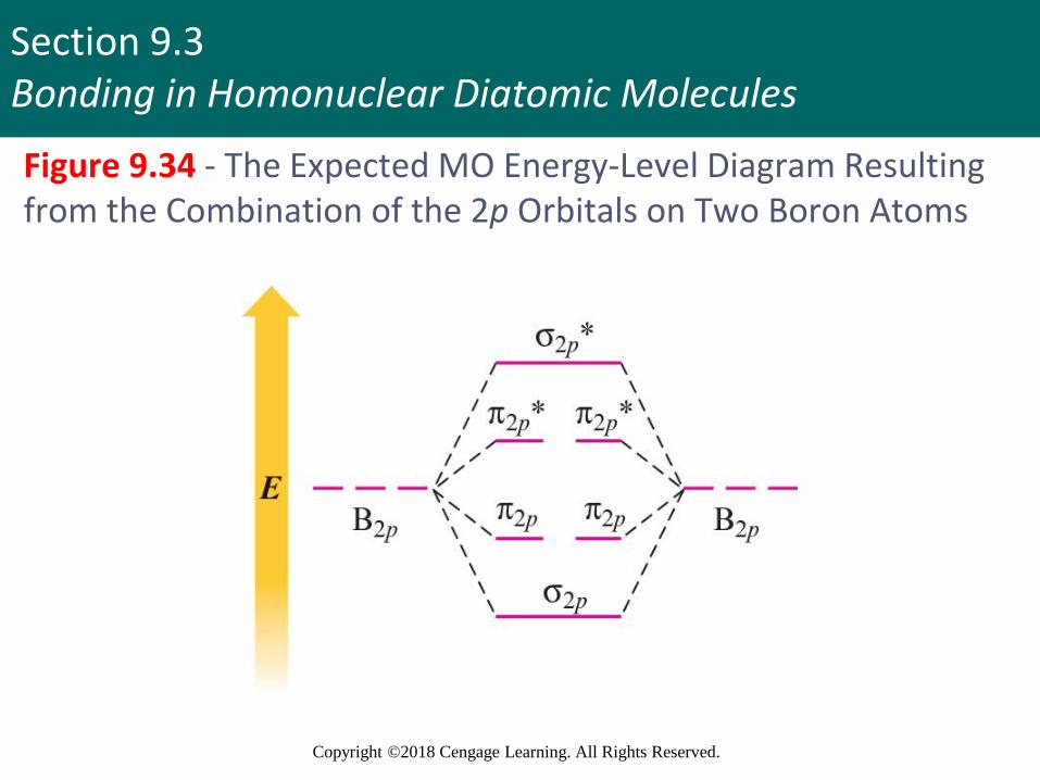
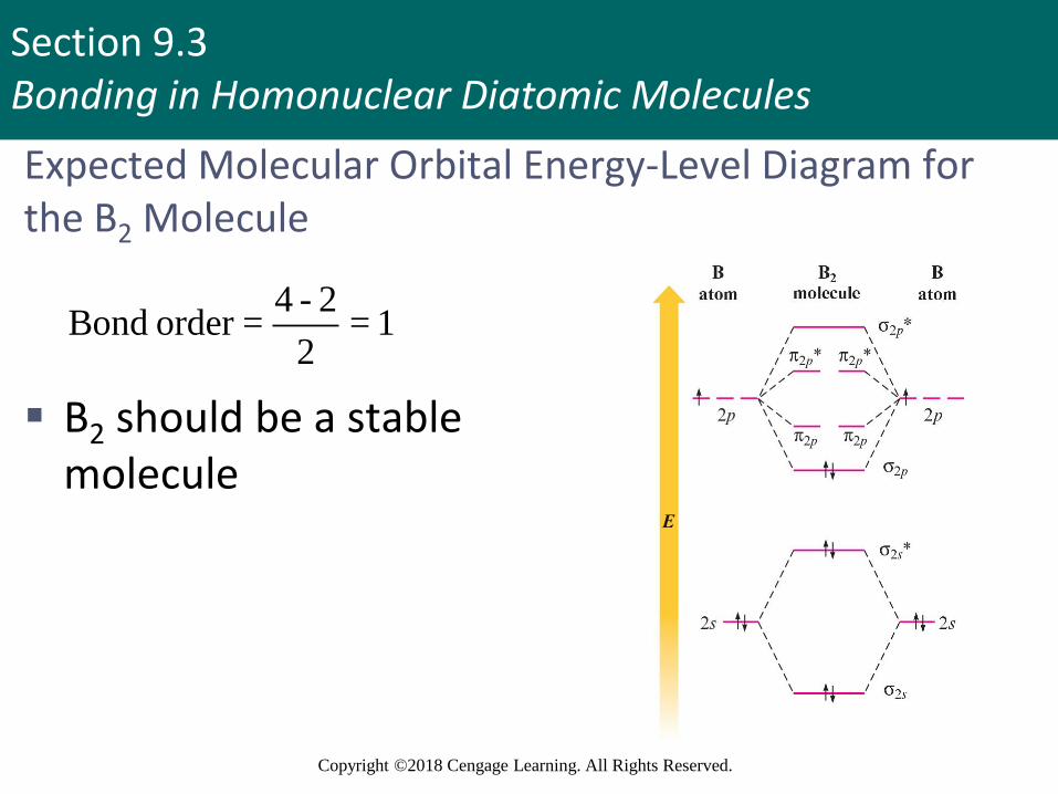
Figure 9.34 - The Expected MO Energy-Level Diagram Resulting from the Combination of the 2p Orbitals on Two Boron Atoms
Section 9.3Bonding in Homonuclear Diatomic Molecules
Copyright ©2018 Cengage Learning. All Rights Reserved.
Expected Molecular Orbital Energy-Level Diagram for the B2 Molecule
4 - 2Bond order = = 1
2
▪ B2 should be a stable molecule

Section 9.3Bonding in Homonuclear Diatomic Molecules
Copyright ©2018 Cengage Learning. All Rights Reserved.
Types of Magnetism in the Presence of a Magnetic Field
▪ Paramagnetism: Substance is attracted into the inducing magnetic field
▪ Associated with unpaired electrons
▪ Diamagnetism: Substance is repelled from the inducing magnetic field
▪ Associated with paired electrons
▪ Substance that has both paired and unpaired electrons will exhibit a net paramagnetism
Copyright © Cengage Learning. All rights reserved 75
Section 9.3Bonding in Homonuclear Diatomic Molecules
Copyright ©2018 Cengage Learning. All Rights Reserved.
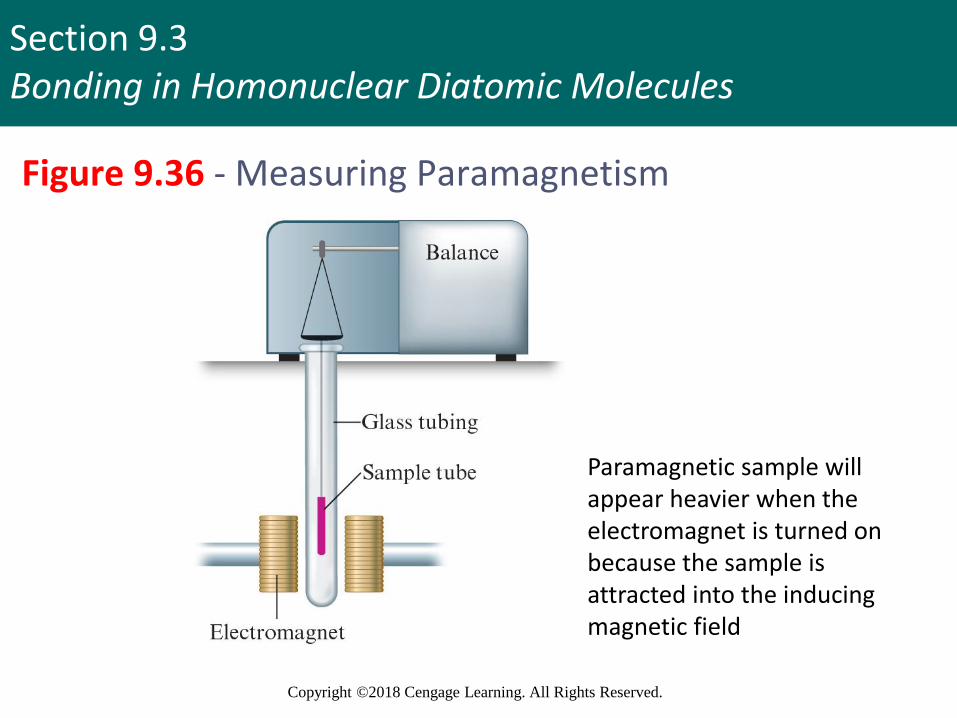
Figure 9.36 - Measuring Paramagnetism
Paramagnetic sample will appear heavier when the electromagnet is turned on because the sample is attracted into the inducing magnetic field

Section 9.3Bonding in Homonuclear Diatomic Molecules
Copyright ©2018 Cengage Learning. All Rights Reserved.
Figure 9.37 - The Correct Molecular Orbital Energy-Level Diagram for B2
▪ Diagram explains the observedparamagnetism of B2
▪ When p–s mixing is allowed, the energies of the σ2pand π2p
orbitals are reversed
▪ Two electrons from the B 2p orbitals now occupy separate, degenerate π2p molecular orbitals and have parallel spins

Section 9.3Bonding in Homonuclear Diatomic Molecules
Copyright ©2018 Cengage Learning. All Rights Reserved.
Critical Thinking
▪ What if 2p orbitals were lower in energy than 2p
orbitals?
▪ What would you expect the B2 molecular orbital energy-level diagram to look like (without considering p–s mixing)?
▪ Compare the expected diagram to Figures 9.34 and 9.35, and state the differences from each

Section 9.3Bonding in Homonuclear Diatomic Molecules
Copyright ©2018 Cengage Learning. All Rights Reserved.
Figure 9.38 - Molecular Orbital Summary of Second-Row Diatomic Molecules
Section 9.3Bonding in Homonuclear Diatomic Molecules
Copyright ©2018 Cengage Learning. All Rights Reserved.
Key Points regarding Period 2 Diatomics
▪ There are definite correlations between bond order, bond energy, and bond length
▪ Bond order cannot be associated with a particular bond energy
▪ N2 molecule will have a triple bond because of the large bond energy associated with it
▪ The O2 molecule is paramagnetic
Section 9.3Bonding in Homonuclear Diatomic Molecules
Copyright ©2018 Cengage Learning. All Rights Reserved.
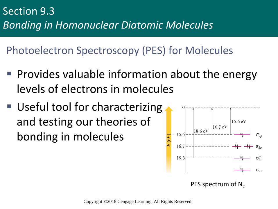
Photoelectron Spectroscopy (PES) for Molecules
▪ Provides valuable information about the energy levels of electrons in molecules
▪ Useful tool for characterizingand testing our theories ofbonding in molecules
PES spectrum of N2
Section 9.3Bonding in Homonuclear Diatomic Molecules
Copyright ©2018 Cengage Learning. All Rights Reserved.
Interactive Example 9.7 - The Molecular Orbital Model II
▪ Use the molecular orbital model to predict the bond order and magnetism of each of the following molecules
a. Ne2
b. P2
Section 9.3Bonding in Homonuclear Diatomic Molecules
Copyright ©2018 Cengage Learning. All Rights Reserved.
Interactive Example 9.7 - Solution (a)
▪ Valence orbitals for Ne are 2s and 2p
▪ Ne2 molecule has 16 valence electrons (8 from each atom)
Section 9.3Bonding in Homonuclear Diatomic Molecules
Copyright ©2018 Cengage Learning. All Rights Reserved.
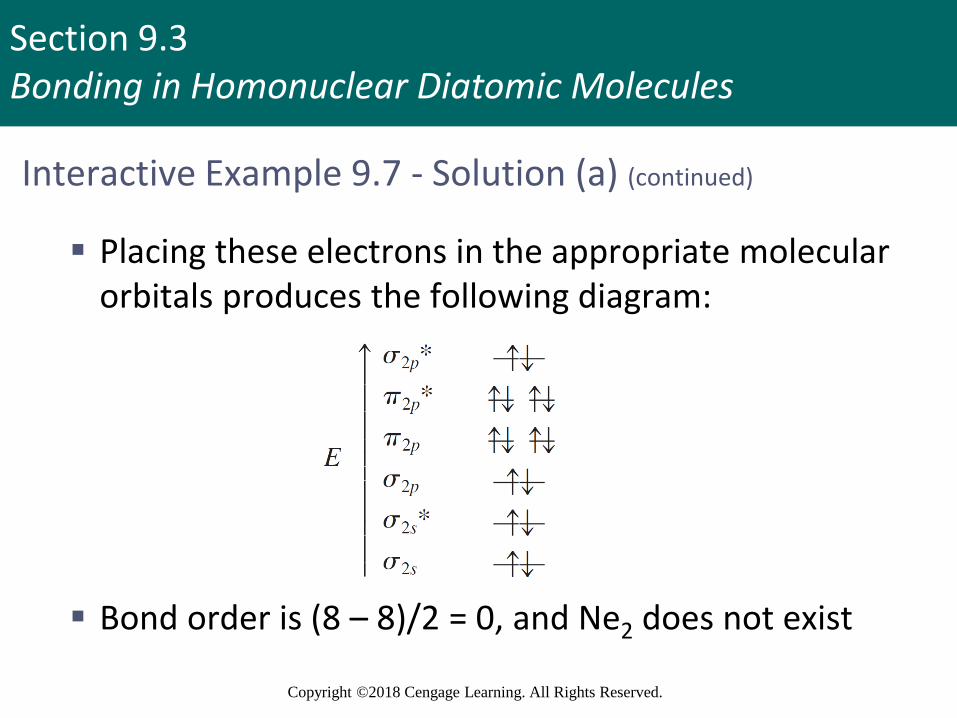
Interactive Example 9.7 - Solution (a) (continued)
▪ Placing these electrons in the appropriate molecular orbitals produces the following diagram:
▪ Bond order is (8 – 8)/2 = 0, and Ne2 does not exist
Section 9.3Bonding in Homonuclear Diatomic Molecules
Copyright ©2018 Cengage Learning. All Rights Reserved.
Interactive Example 9.7 - Solution (b)
▪ P2 contains phosphorus atoms from the third row of the periodic table
▪ Assume that the diatomic molecules of the Period 3 elements can be treated in a way similar to that which has been used so far
▪ Draw the MO diagram for P2 analogous to that for N2
▪ The only change will be that the molecular orbitals will be formed from 3s and 3p atomic orbitals
Section 9.3Bonding in Homonuclear Diatomic Molecules
Copyright ©2018 Cengage Learning. All Rights Reserved.
Interactive Example 9.7 - Solution (b) (continued)
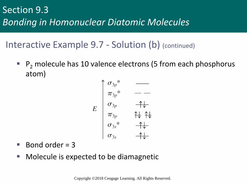
▪ P2 molecule has 10 valence electrons (5 from each phosphorus atom)
▪ Bond order = 3
▪ Molecule is expected to be diamagnetic

Section 9.3Bonding in Homonuclear Diatomic Molecules
Copyright ©2018 Cengage Learning. All Rights Reserved.
Join In (9)
▪ Which of the following is paramagnetic?
a. B2
b. C2
c. H2
d. N2

Section 9.3Bonding in Homonuclear Diatomic Molecules
Copyright ©2018 Cengage Learning. All Rights Reserved.
Join In (10)
▪ Which of the following is diamagnetic?
a. N2−
b. N2+
c. O2
d. N2
Section 9.3Bonding in Homonuclear Diatomic Molecules
Copyright ©2018 Cengage Learning. All Rights Reserved.
Join In (11)
▪ Which of the following statements is false?
a. Atoms or molecules with an even number of electrons are diamagnetic
b. Atoms or molecules with an odd number of electrons are paramagnetic
c. Paramagnetism cannot be deduced solely from the Lewis structure of a molecule
d. Paramagnetic molecules are attracted toward a magnetic field

Section 9.4Bonding in Heteronuclear Diatomic Molecules
Copyright ©2018 Cengage Learning. All Rights Reserved.
Heteronuclear Diatomic Molecules
▪ Heteronuclear: Different atoms
▪ A special case involves molecules containing atoms adjacent to each other in the periodic table
▪ MO diagram can be used for homonuclear molecules as atoms involved in such molecules are similar
Copyright © Cengage Learning. All rights reserved 90
Section 9.4Bonding in Heteronuclear Diatomic Molecules
Copyright ©2018 Cengage Learning. All Rights Reserved.
Interactive Example 9.8 - The Molecular Orbital Model III
▪ Use the molecular orbital model to predict the magnetism and bond order of the NO+ and CN–
ions
Section 9.4Bonding in Heteronuclear Diatomic Molecules
Copyright ©2018 Cengage Learning. All Rights Reserved.
Interactive Example 9.8 - Solution
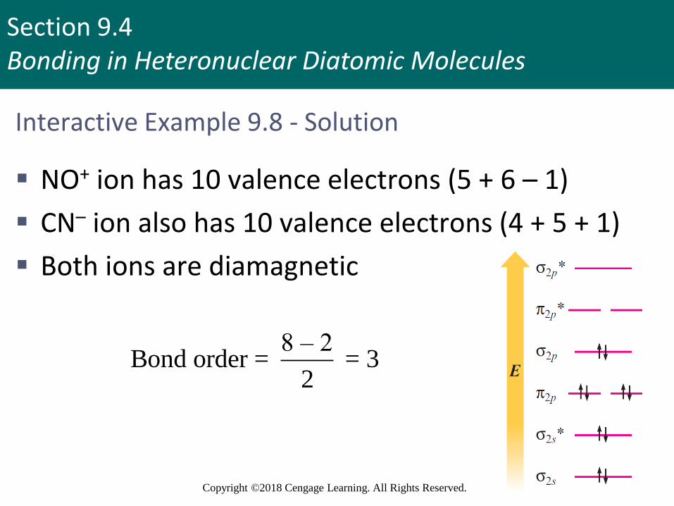
▪ NO+ ion has 10 valence electrons (5 + 6 – 1)
▪ CN– ion also has 10 valence electrons (4 + 5 + 1)
▪ Both ions are diamagnetic
8 – 2Bond order = = 3
2
Section 9.4Bonding in Heteronuclear Diatomic Molecules
Copyright ©2018 Cengage Learning. All Rights Reserved.
Energy-Level Diagrams for Diatomic Molecules
▪ When the two atoms of a diatomic molecule are very different, the energy-level diagram for homonuclear molecules cannot be used
▪ Consider the hydrogen fluoride (HF) molecule
▪ Electron configuration of hydrogen - 1s1
▪ Electron configuration of fluorine - 1s22s22p5
▪ Assume that fluorine uses only one of its 2p orbitals to bond to hydrogen
Section 9.4Bonding in Heteronuclear Diatomic Molecules
Copyright ©2018 Cengage Learning. All Rights Reserved.
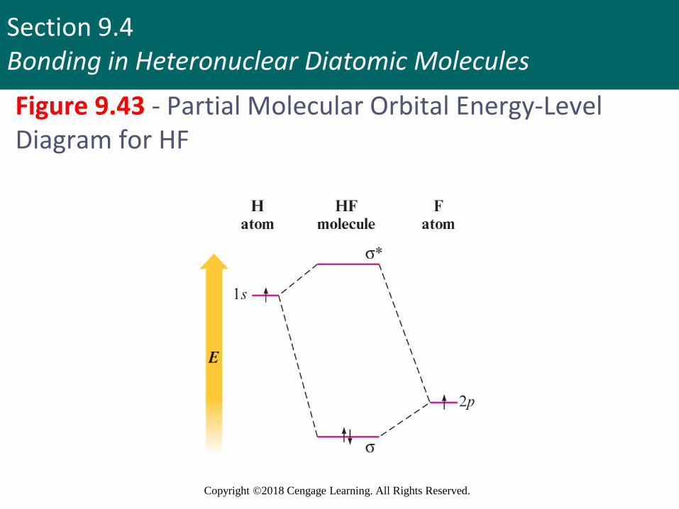
Figure 9.43 - Partial Molecular Orbital Energy-Level Diagram for HF
Section 9.4Bonding in Heteronuclear Diatomic Molecules
Copyright ©2018 Cengage Learning. All Rights Reserved.
Energy-Level Diagrams for Diatomic Molecules (continued)
▪ HF molecule should be stable as both electrons are lowered in energy relative to their energy in the free hydrogen and fluorine atoms
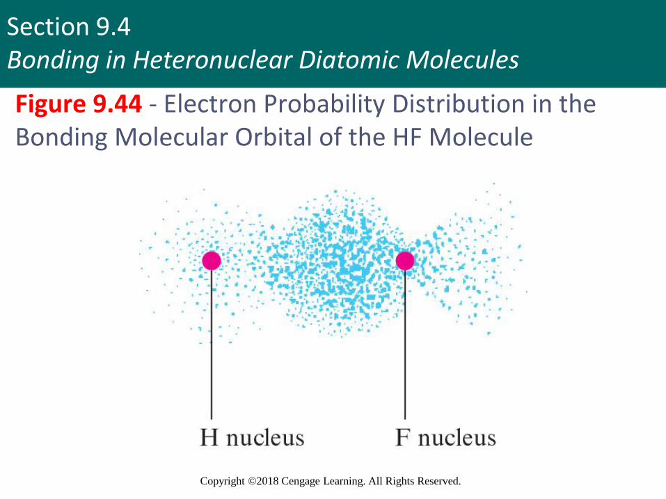
▪ Electrons prefer to be closer to the fluorine atom
▪ Electron pair is not shared equally
▪ Fluorine has a slight excess of negative charge, and hydrogen is partially positive
Section 9.4Bonding in Heteronuclear Diatomic Molecules
Copyright ©2018 Cengage Learning. All Rights Reserved.
Figure 9.44 - Electron Probability Distribution in the Bonding Molecular Orbital of the HF Molecule
Section 9.4Bonding in Heteronuclear Diatomic Molecules
Copyright ©2018 Cengage Learning. All Rights Reserved.
Join In (12)
▪ Consider the molecular orbital description of the NO– anion
▪ Which of the following statements is false?
a. NO– is paramagnetic
b. NO– is isoelectronic with CO
c. The bond energy in NO+ is greater than the bond energy in NO–
d. The bond order in NO– is 2

Section 9.5Combining the Localized Electron and Molecular Orbital Models
Copyright ©2018 Cengage Learning. All Rights Reserved.
Combining the Localized Electron and MO Models
▪ The bonds in a molecule can be described as being localized
▪ The bonds must be treated as being delocalized
▪ For molecules that require resonance:
▪ Localized electron model can be used to describe the σ bonding
▪ MO model can be used to describe the π bonding
Section 9.5Combining the Localized Electron and Molecular Orbital Models
Copyright ©2018 Cengage Learning. All Rights Reserved.
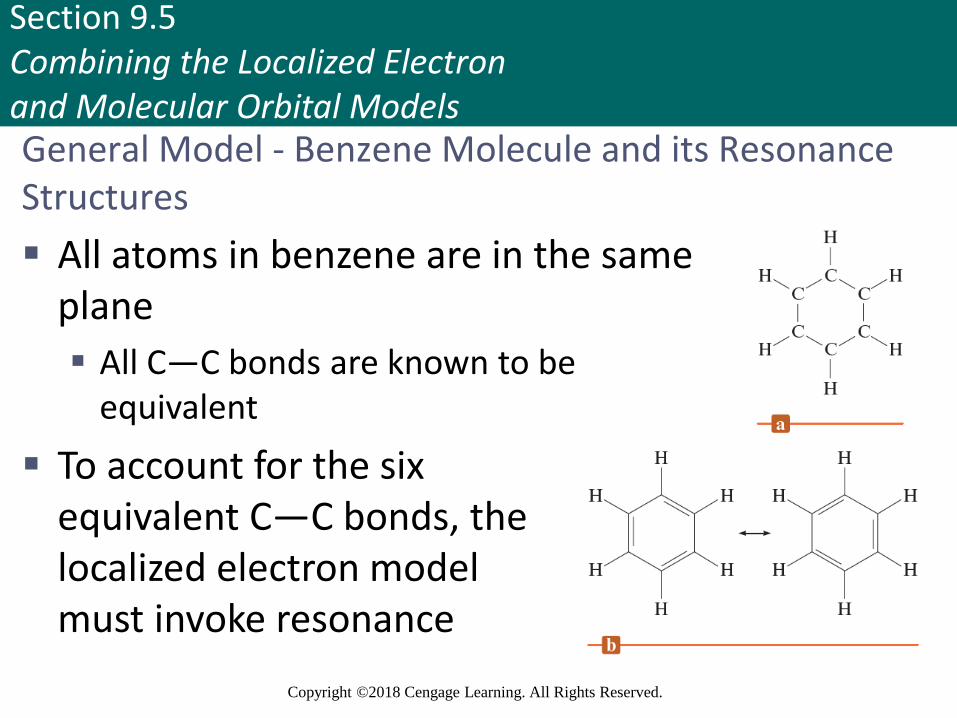
General Model - Benzene Molecule and its Resonance Structures
▪ All atoms in benzene are in the same plane
▪ All C—C bonds are known to be equivalent
▪ To account for the six equivalent C—C bonds, the localized electron model must invoke resonance
Section 9.5Combining the Localized Electron and Molecular Orbital Models
Copyright ©2018 Cengage Learning. All Rights Reserved.
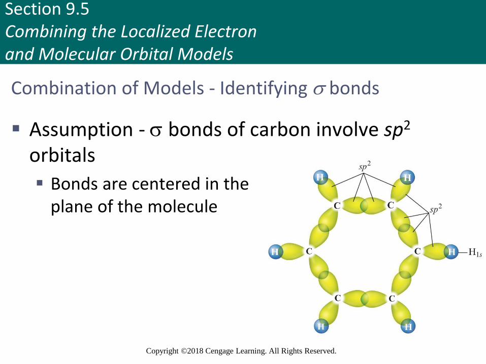
Combination of Models - Identifying bonds
▪ Assumption - bonds of carbon involve sp2
orbitals
▪ Bonds are centered in theplane of the molecule
Section 9.5Combining the Localized Electron and Molecular Orbital Models
Copyright ©2018 Cengage Learning. All Rights Reserved.
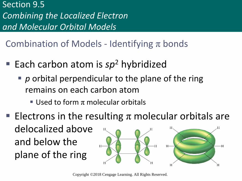
Combination of Models - Identifying π bonds
▪ Each carbon atom is sp2 hybridized
▪ p orbital perpendicular to the plane of the ring remains on each carbon atom
▪ Used to form π molecular orbitals
▪ Electrons in the resulting π molecular orbitals are delocalized aboveand below theplane of the ring
Section 9.5Combining the Localized Electron and Molecular Orbital Models
Copyright ©2018 Cengage Learning. All Rights Reserved.
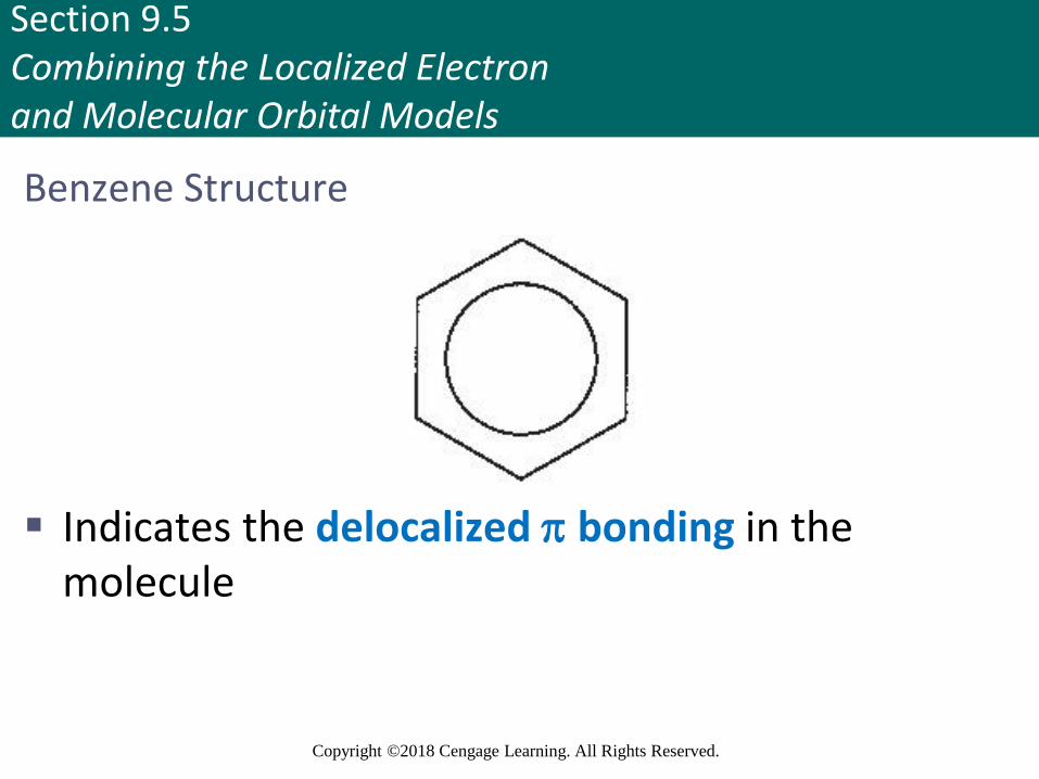
Benzene Structure
▪ Indicates the delocalized bonding in the molecule