Embed Size (px)
Citation preview

BUREAU OF LOCAL ROADS AND STREETS MANUAL
Chapter Thirty-four
INTERSECTIONS


BUREAU OF LOCAL ROADS & STREETS Jan 2006 INTERSECTIONS 34(i)
Chapter Thirty-four INTERSECTIONS
Table of Contents
Section Page 34-1 GENERAL DESIGN CONTROLS ........................................................................... 34-1(1)
34-1.01 Intersection Alignment ........................................................................... 34-1(1) 34-1.01(a) Angled Intersections ......................................................... 34-1(1) 34-1.01(b) Intersections on Curves .................................................... 34-1(2) 34-1.01(c) Offset Intersections........................................................... 34-1(5) 34-1.01(d) Roundabouts .................................................................... 34-1(7)
34-1.02 Profiles................................................................................................... 34-1(8)
34-1.02(a) Profiles at Intersections..................................................... 34-1(8) 34-1.02(b) Cross-Section Transitions................................................. 34-1(12) 34-1.02(c) Drainage ........................................................................... 34-1(13)
34-1.03 Intersection Capacity Analysis............................................................... 34-1(13) 34-1.04 Design Vehicles..................................................................................... 34-1(14)
34-1.04(a) Types ................................................................................ 34-1(14) 34-1.04(b) Selection ........................................................................... 34-1(14)
34-1.05 Pedestrians and Bicyclists..................................................................... 34-1(17)
34-2 TURNING RADII ..................................................................................................... 34-2(1)
34-2.01 Design for Right-Turning Vehicles......................................................... 34-2(1)
34-2.01(a) Design Vehicle.................................................................. 34-2(1) 34-2.01(b) Inside Clearance............................................................... 34-2(1) 34-2.01(c) Encroachment................................................................... 34-2(1) 34-2.01(d) Pedestrian/Bicyclist Considerations.................................. 34-2(2) 34-2.01(e) Types of Right-Turn Designs ............................................ 34-2(2) 34-2.01(f) Curbing ............................................................................. 34-2(4) 34-2.01(g) Stop Sign Locations.......................................................... 34-2(4) 34-2.01(h) Turning Template(s).......................................................... 34-2(4)
34-2.02 Left-Turn Control Radii .......................................................................... 34-2(4)

BUREAU OF LOCAL ROADS & STREETS 34(ii) INTERSECTIONS Jan 2006
Table of Contents (Continued)
Section Page 34-3 AUXILIARY TURN LANES...................................................................................... 34-3(1)
34-3.01 Turn Lane Guidelines ............................................................................ 34-3(1) 34-3.01(a) Right-Turn Lanes .............................................................. 34-3(1) 34-3.01(b) Left-Turn Lanes ................................................................ 34-3(1)
34-3.02 Design of Turn Lanes ............................................................................ 34-3(2)
34-3.02(a) Turn Lane Widths ............................................................. 34-3(2) 34-3.02(b) Turn Lane Lengths............................................................ 34-3(2)
34-3.03 Typical Treatments for Auxiliary Turn Lanes ......................................... 34-3(6) 34-3.04 Dual Turn Lanes .................................................................................... 34-3(10)
34-3.04(a) Guidelines......................................................................... 34-3(10) 34-3.04(b) Design............................................................................... 34-3(10)
34-4 ISLANDS................................................................................................................. 34-4(1)
34-4.01 Island Types .......................................................................................... 34-4(1) 34-4.02 Selection of Island Type ........................................................................ 34-4(1)
34-4.02(a) Flush or Traversable Islands............................................. 34-4(2) 34-4.02(b) Raised-Curb Islands ......................................................... 34-4(2) 34-4.02(c) Divisional Islands .............................................................. 34-4(3) 34-4.02(d) Corner Islands .................................................................. 34-4(3) 34-4.02(e) Curb Ramps...................................................................... 34-4(6)
34-4.03 Median Openings .................................................................................. 34-4(6)
34-5 EXTENSION OF THROUGH LANES BEYOND AN INTERSECTION.................... 34-5(1) 34-6 INTERSECTION DESIGN NEAR RAILROADS...................................................... 34-6(1)
34-6.01 General Design Considerations............................................................. 34-6(1) 34-6.02 Interconnection Traffic Signal System Design....................................... 34-6(2) 34-6.03 Signing................................................................................................... 34-6(2)

BUREAU OF LOCAL ROADS & STREETS Aug 2007 INTERSECTIONS 34-1(1)
Chapter Thirty-four INTERSECTIONS
Intersections are an important part of the highway system. The operational efficiency, capacity, safety, and cost of the overall system are largely dependent upon its design, especially in urban areas. The primary objective of intersection design is to provide for the convenience, ease, comfort, and safety of those traversing the intersection while reducing potential conflicts between vehicles, bicycles, and pedestrians. Chapter 34 provides guidance in the design of intersections including alignment, profile, design vehicles, turning radii, right-turning roadways, left- and right-turn lanes, channelized islands, and intersections near railroads. Information that is also applicable to intersections is included in the following sources: • Guidelines for preparing and processing intersection design studies are discussed in
Chapter 10.
• Application of bicycle lanes through intersections is discussed in Chapter 42 of the BLRS Manual and Chapter 17 of the BDE Manual.
• Intersection sight distance is discussed in Chapter 28.
• The various curb types used for channelization, islands, and medians are discussed in Chapter 31.
• Two-way, left-turn lanes are discussed in Chapter 31 and Chapter 36 of the BDE Manual.
• Criteria for intersections on 3R projects are discussed in Chapter 33.
• Curb ramps for disabled accessibility at intersections are discussed in Chapter 41.
• Other intersection design features (e.g., intersection types, intersection spacing, turn-lane guidelines) can be found in Chapter 36 of the BDE Manual and the AASHTO Policy on Geometric Design of Highways and Streets (Green Book).
• Where a local facility intersects with a State facility, the design of the intersection as it affects the State highway will be in accordance with Chapter 36 of the BDE Manual.
34-1 GENERAL DESIGN CONTROLS
34-1.01 Intersection Alignment
34-1.01(a) Angled Intersections
Highways should intersect at right angles. Intersections at acute angles are undesirable because they: • restrict vehicular turning movements,
• require additional pavement and channelization for large trucks,

BUREAU OF LOCAL ROADS & STREETS 34-1(2) INTERSECTIONS Aug 2007 • increase the exposure time for vehicles and pedestrians crossing the main traffic flow, and
• restrict the crossroad sight distance. Preferably, the angle of intersection should be within 15° of the perpendicular. This amount of skew can often be tolerated because the impact on sight lines and turning movements is not significant. Under restricted conditions where obtaining the right-of-way to straighten the angle of intersection would be impractical, an intersection angle up to 30° from the perpendicular may be used. Where turning movements are significantly unbalanced, the intersections may be angled to favor the predominant movement. Intersection angles beyond these ranges may warrant more positive traffic control (e.g., all stop, traffic signals) or geometric improvements (e.g., realignment, greater corner sight distance). Avoid using short-radius curves or abnormal travel paths near the intersection simply to reduce the intersection skew. Figure 34-1A illustrates various angles of intersections and potential improvements to the alignment. 34-1.01(b) Intersections on Curves
Preferably, all legs of an intersection should be on a tangent section. Where a minor road intersects a major road on a horizontal curve, the geometric design of the intersection becomes significantly more complicated, particularly for sight distance, turning movements, channelization, and superelevation. The following guidelines address horizontal alignment at intersections: 1. Realignment. If relocation of the intersection is not practical, the designer may be able
to realign the minor road to intersect the major road perpendicular to a tangent on the horizontal curve; see example “E” in Figure 34-1A. Although an improvement, this arrangement may still result in difficult turning movements due to superelevation on the major road.
2. Superelevation on the Major Road. If the major road is on a horizontal curve, the major road superelevation rate must be minimized so that slowing or stopped vehicles do not slide across the pavement during wet or icy conditions. Figure 34-1B provides the criteria for the maximum superelevation rate that should be used where a crossroad intersects a superelevated highway.

BUREAU OF LOCAL ROADS & STREETS Aug 2007 INTERSECTIONS 34-1(3) Notes: 1. Where there are high volumes of left turns from the major road, avoid using the offset
intersection alignment illustrated in “C.” 2. Revised alignments “C” and “D” are not desirable in agricultural areas with large
numbers of farm vehicles crossing the major road.
REALIGNMENT OF INTERSECTIONS
Figure 34-1A

BUREAU OF LOCAL ROADS & STREETS 34-1(4) INTERSECTIONS Aug 2007
Type of Improvement Category Maximum Superelevation Rate “e” for Intersections on Curve
“New Construction” at a major crossroad (> 400 ADT) 6% (4% Desirable)
To remain in place with “Reconstruction” at a major crossroad 6%
To remain in place with “Reconstruction” at a minor crossroad 8%
INTERSECTIONS AND SUPERELEVATED MAJOR ROAD
Figure 34-1B

BUREAU OF LOCAL ROADS & STREETS Aug 2007 INTERSECTIONS 34-1(5) 3. Curved Approach. Where a local road is on a curved alignment and is approaching a
stop condition, special consideration is required in the design of the horizontal curvature prior to the intersection. When designing this type of an approach, the designer should consider the following guidelines:
• To design the horizontal curve, assume a design speed of 20 mph (30 km/h) less than the approach speed, but not less than 30 mph (50 km/h) for design speeds less than or equal to 50 mph (80 km/h).
• The superelevation rate on the approach curve to an intersection should be limited to a maximum superelevation rate of 6% or less. The objective is to use as flat an alignment as practical with lower superelevation. The preferred design is to maintain a normal crown section through the curve relying on the friction factor rather than superelevation. The minimum radius should not be less than that permitted for the highway classification based on the selected design of the approach curve, rural or urban location, and the superelevation rate (i.e., maximum of 6%). For additional guidance on horizontal curve designs, see Chapter 29.
• Provide a tangent section equal to 2/3 of the superelevation transition length prior to the intersection radius returns. This will allow for the superelevation runoff to be developed outside of the intersection radius returns; see Figure 36-1F of the BDE Manual.
This procedure recognizes the need to accommodate a reasonable operating speed on a stop-controlled approach, while minimizing the potential for adverse operations on superelevated pavements during snow and ice conditions.
34-1.01(c) Offset Intersections
In general, 4-leg intersections should be designed so that opposing approaches line up with each other (i.e., there is no offset between opposing approaches). However, this is not always practical. Because of possible conflicts with overlapping turning vehicles, offset intersections should only be allowed to remain on low-volume approaches. Also, consider the following: 1. Maximum Offset. The maximum offset is determined from the application of a taper
equal to V:1 (0.6V:1) applied to the intersection width, where V is the design speed in miles per hour (kilometers per hour); see Figure 34-1C. In restricted locations and where V ≤ 45 mph (70 km/h), the applied taper may be V2/60 (V2/155). V is selected as follows:
• V = 20 mph (30 km/h) for stop-controlled approaches.
• V = the roadway design speed for the free-flowing approaches at a stop-controlled intersection.

BUREAU OF LOCAL ROADS & STREETS 34-1(6) INTERSECTIONS Aug 2007
• V = the roadway design speed for the offset approaches at a signalized intersection.
Notes: 1. Desirable taper rate is V:1 (0.6V:1), where V = design speed in mph (km/h). 2. See discussion in Section 34-1.01(c) for more information.
OFFSET INTERSECTION
Figure 34-1C
BUREAU OF LOCAL ROADS & STREETS Aug 2007 INTERSECTIONS 34-1(7) 2. Turning Conflicts. Evaluate the entire intersection for conflicts that may result from
turning vehicles at an offset intersection. For example, offsets where the “jog” is to the left may result in significant interference between simultaneous left-turning vehicles.
3. Evaluation Factors. In addition to potential vehicular conflicts, the designer should evaluate the following at existing or proposed offset intersections:
• through and turning volumes;
• type of traffic control;
• impact on all turning maneuvers;
• intersection geometrics (e.g., sight distance, curb/pavement edge radii); and
• crash history at existing intersections.
34-1.01(d) Roundabouts
Roundabouts are circular intersections with specific design and traffic control features. These features include yield control of all entering traffic, channelized approaches, and appropriate geometric curvature to ensure that travel speeds on the circulatory roadway are typically less than 30 mph (50 km/h). Roundabouts are defined by the following two basic operational and design principles: 1. Yield-at-Entry. Yield-at-entry is also known as off-side priority or the yield-to-left rule.
Yield-at-entry requires that vehicles on the circulatory roadway of the roundabout have the right-of-way and all entering vehicles on the approaches have to wait for a gap in the circulating flow. To maintain free flow and high capacity, yield signs are used as the entry control. As opposed to nonconforming traffic circles, roundabouts are not designed for weaving maneuvers, thus permitting smaller diameters. Even for multilane roundabouts, weaving maneuvers are not considered a design or capacity criterion.
2. Deflection of Entering Traffic. Entrance roadways that intersect the roundabout along a
tangent to the circulatory roadway are not permitted. Instead, entering traffic is deflected to the right by the central island of the roundabout and by channelization at the entrance into an appropriate curved path along the circulating roadway. Thus, no traffic is permitted to follow a straight path through the roundabout.
Roundabouts range in size from mini-roundabouts with inscribed circle diameters as small as 50 ft (15 m), to compact roundabouts with inscribed circle diameters between 100 ft and 115 ft (30 m and 35 m), to large roundabouts, often with multilane circulating roadways and more than four entries up to 500 ft (150 m) in diameter. However, the greater speeds permitted by larger roundabouts, with inscribed circle diameters greater than 250 ft (75 m), may reduce their safety benefits. Designing the geometry of a roundabout involves choosing the best operational and capacity performance while retaining the best safety enhancements. Roundabouts operate best when

BUREAU OF LOCAL ROADS & STREETS 34-1(8) INTERSECTIONS Aug 2007 their geometry forces traffic to enter and circulate at slow speeds. Horizontal curvature and narrow pavement widths are used to produce this reduced-speed environment. However, the capacity of roundabouts is negatively affected by these low-speed design elements. As the widths and radii of the entry and circulatory roadways are reduced, the capacity of the roundabout is also reduced. Furthermore, many of the geometric criteria used in design of roundabouts are governed by the maneuvering needs of the largest vehicles expected to travel through the intersection. Thus, designing a roundabout is a process of determining the optimal balance between safety provisions, operational performance, and the accommodation of over-sized vehicles. Reasons why the designer may consider installing a roundabout include the following: • community enhancement,
• traffic calming,
• safety improvement,
• operational improvement, and/or
• a special situation. For detailed information on roundabouts, see FHWA’s publication, Roundabouts: An Informational Guide. 34-1.02 Profiles
The design should avoid combinations of grade lines that make vehicular control difficult at intersections. To accomplish this, consider the profile for all roadway approaches to and through the intersection. The following criteria will apply. 34-1.02(a) Profiles at Intersections
1. Gradients. The area on approaches that will be used for storage of stopped vehicles is commonly referred to as the storage space or storage platform. Intersection gradients should be as flat as practical but not be greater than 5.0%. Note that approach gradients of 3.0% or steeper may require correction of certain design factors to produce operating conditions equivalent to those on level highways (e.g., stopping sight distances, deceleration lengths). However, any gradient through the intersection must reflect the practicalities of matching the basic profiles of the intersecting roadways and shoulders. On major side roads, the storage platform gradient should be a minimum of 1.0% and a maximum of 2.0% draining away from the mainline highway. When other local roads intersect a State highway, the maximum gradient may be 4.0% draining away from the State highway. Maintain this gradient through the expected storage distance on that leg. At a minimum, provide the storage platform gradient on the side road for a distance of 30 ft to 50 ft (9 m to 15 m) beyond the edge of the mainline travelway or to the ditch line of an arterial highway.

BUREAU OF LOCAL ROADS & STREETS Aug 2007 INTERSECTIONS 34-1(9) 2. Crossover Slope. The algebraic difference between the main highway cross slope and
side road gradient should not exceed the rollover guidelines described in Figure 34-1D. 3. Transitions. Where the cross section of the minor road is transitioned to meet the major
road, provide a vertical curve between the side road approach gradient and the mainline pavement, especially when traffic signals may be needed; see Figures 34-1E and 34-1F. The design speed of the vertical approach alignment may be up to 20 mph (30 km/h) less than the project design, but not less than design speed of 30 mph (50 km/h). The following vertical curve options are presented in order from the most desirable to the least desirable:
a. Vertical Curves (SSD). The criteria for stopping sight distance as described in
Section 30-2 should be used for the vertical curve. For non-stopped conditions, design the vertical curve based on the design speed of the highway. For stopped-conditions, design the vertical curve using a 30 mph (50 km/h) design speed.
b. Sag Vertical Curves (Minimum Comfort). Under restricted conditions where the
SSD criteria is not practical, the sag vertical curves at intersection approaches may be based on the following formulas:
K = (0.1V)2 (US Customary) K = (0.034V)2 (Metric)
L = KA
Rollover Factor Guidelines
“New Construction” at a major crossroad (> 400 ADT)
5% Desirable Maximum 6% Maximum
To remain in place with “Reconstruction” at a major crossroad
7% Desirable Maximum 8% Maximum
To remain in place with “Reconstruction” at a minor crossroad
9% Desirable Maximum 10% Maximum
ROLLOVER FACTOR GUIDELINES
Figure 34-1D

BUREAU OF LOCAL ROADS & STREETS 34-1(10) INTERSECTIONS Aug 2007
Not
es:
1.
Des
irabl
y, th
e m
inor
roa
d pr
ofile
sho
uld
tie in
to th
e m
ajor
roa
d tra
vel l
ane
cros
s sl
ope;
how
ever
, whe
re th
e m
inor
ro
ad is
sto
p-co
ntro
lled,
it w
ill b
e ac
cept
able
for
the
min
or r
oad
prof
ile t
o tie
into
the
maj
or r
oute
sho
ulde
r cr
oss
slop
e.
2.
See
Sec
tion
34-1
.02(
a) fo
r sto
rage
pla
tform
gra
dien
ts.
3.
Che
ck F
igur
e 34
-1D
for m
axim
um ro
llove
r rat
es.
VE
RTI
CA
L PR
OFI
LES
OF
RU
RA
L IN
TER
SEC
TIN
G R
OA
DS
Figu
re 3
4-1E

BUREAU OF LOCAL ROADS & STREETS Aug 2007 INTERSECTIONS 34-1(11)
Not
es:
1.
Des
irabl
y, th
e m
inor
roa
d pr
ofile
sho
uld
tie in
to th
e m
ajor
roa
d tra
vel l
ane
cros
s sl
ope;
how
ever
, whe
re th
e m
inor
ro
ad is
sto
p-co
ntro
lled,
it w
ill b
e ac
cept
able
for t
he m
inor
road
pro
file
to ti
e in
to th
e m
ajor
road
sho
ulde
r cro
ss s
lope
.
2.
See
Sec
tion
34-1
.02(
a) fo
r sto
rage
pla
tform
gra
dien
ts.
3.
Che
ck F
igur
e 34
-1D
for m
axim
um ro
llove
r rat
es.
4.
At s
igna
lized
inte
rsec
tions
, the
mos
t des
irabl
e cr
oss
slop
e op
tion
will
be
to tr
ansi
tion
all a
ppro
ach
legs
into
a p
lana
r su
rface
thro
ugh
the
inte
rsec
tion
and
to li
mit
the
cent
erlin
e ro
llove
r on
the
maj
or ro
ad to
2%
- 3%
. 5.
Fo
r a s
igna
l con
trolle
d m
inor
road
des
cend
ing
from
the
maj
or ro
ad, m
aint
ain
the
trave
l lan
e cr
oss
slop
e of
the
maj
or
road
way
thro
ugh
the
leng
th o
f the
sto
rage
pla
tform
.
VER
TIC
AL
PRO
FILE
S O
F U
RB
AN
INTE
RSE
CTI
NG
STR
EETS
Figu
re 3
4-1F

BUREAU OF LOCAL ROADS & STREETS 34-1(12) INTERSECTIONS Aug 2007
Where: K = horizontal distance needed to produce a 1% change in the gradient along
the curve, ft/% (m/%) A = algebraic difference between the two tangent grades, % V = design speed, mph (km/h) L = length of vertical curve, ft (m)
4. Angular Breaks. At stop-controlled intersections, angular breaks are typically provided
when transitioning the cross section of the minor approach to meet the major road cross section. Figures 34-1E and 34-1F present schematics of vertical profiles through intersections for rural and urban conditions. Figure 34-1D provides the maximum rollover guidelines that are also applicable for changes in angular breaks.
5. Grade Lines. The principals for coordinating the horizontal and vertical alignment discussed in Chapter 30 are also applicable to vertical profiles through intersections. In addition, do not place intersections on or near crest vertical curves unless the vertical curve is flat enough for the intersection pavement to be seen assuming decision sight distance.
34-1.02(b) Cross-Section Transitions
One or more of the approaching legs of an intersection may need to be transitioned to meet the cross section of the two crossing roads. The following applies: 1. Stop-Controlled. Where the minor road is stop-controlled, maintain the profile and cross
section of the major road through an intersection and transition the cross slope of the stop-controlled roadway to match the major road cross slope and profile.
2. Signalized Intersection. At signalized intersections, or potentially signalized intersections, transition the cross section of the minor road to meet the profile and cross slope of the major road. Where compromises are necessary between two major roadways, provide the smoother riding characteristics to the roadway with the higher traffic volumes and operating speeds.
3. Transition Rates. Where one or both intersecting roadways are transitioned, the designer must determine the length and rate of transition from the typical section to the modified section. Desirably, design the transition to meet the general principles of superelevation transition that apply to that roadway (i.e., open-roadway or low-speed urban street conditions). When these criteria are applied to intersection transition rates, the applied design speed is typically:

BUREAU OF LOCAL ROADS & STREETS Aug 2007 INTERSECTIONS 34-1(13)
• 20 mph (30 km/h) below the design speed but not less than 30 mph (50 km/h) for a stop-controlled roadway,
• the highway design speed for a free-flowing roadway, or
• the highway design speed on each roadway of a signalized intersection.
At a minimum and consistent with field conditions, transition the approach pavements of an urban intersection within the curb or radius returns and for rural intersections within a distance of 50 ft (15 m).
34-1.02(c) Drainage
Evaluate the profile and transitions at all intersections for impacts on drainage. This is especially important for channelized intersections on curves and grades. This may require the designer to check superelevation transition lengths to ensure flat sections are minimized. Low points on approach roadway profiles should be beyond a raised corner island to prevent water from being trapped and causing ponding. 34-1.03 Intersection Capacity Analysis
Capacity analysis influences several geometric design features including the number of approach lanes, auxiliary lanes, lane widths, channelization, and number of departure lanes. In addition, this analysis in conjunction with the Illinois Manual on Uniform Traffic Control Devices (ILMUTCD) will determine whether an intersection may need to be signalized or stop-controlled. It is important that the level of service for a signalized intersection be calculated for each lane group (a lane group may be one or more movements), each intersection approach, and the intersection as a whole. Levels of service criteria are provided in the geometric design tables in Chapter 32. Once the minimum level of service has been selected and design traffic volumes are determined, use the Highway Capacity Manual (HCM) and the Highway Capacity Software (HCS) to perform the detailed capacity analyses. Ensure that data used in the analyses are applicable for the intersection (i.e., do not assume the program default values are automatically applicable for the intersection). Other capacity and signal analysis programs may be used provided they are approved for use by the BLRS. To be eligible for approval, the output results must be comparable to the HCS. If the intersection is part of a traffic signal system, check the intersection design with an approved traffic progression program. These programs analyze all signalized intersections in the system to determine the overall capacity of the system. Also, see Figure 36-1C of the BDE Manual.

BUREAU OF LOCAL ROADS & STREETS 34-1(14) INTERSECTIONS Aug 2007 34-1.04 Design Vehicles
34-1.04(a) Types
The design vehicle affects the radius returns, left-turn radii, lane widths, median openings, turning roadways, and sight distances at an intersection. Typical design vehicles used for intersection design are: • P ⎯ Passenger car; includes vans and pickup trucks.
• S-BUS-40 (S-BUS-12) ⎯ 84-passenger school bus.
• SU ⎯ Single-unit truck.
• WB-40 (WB-12) ⎯ Tractor/Semitrailer combination with an overall wheelbase of 40 ft (12.2 m).
• WB-50 (WB-15) ⎯ Tractor/Semitrailer combination with an overall wheelbase of 50 ft (15.2 m).
• WB-55 (WB-17) ⎯ Tractor/Semitrailer combination with an overall wheelbase of 55 ft (16.8 m).
• WB-65 (WB-20) ⎯ Tractor/Semitrailer combination with an overall wheelbase of 65 ft (19.4 m).
• P/T ⎯ Recreational vehicle, car, and camper trailer. Chapter 36 of the BDE Manual and the AASHTO Green Book provide the vehicular dimensions and turning templates for each of the above design vehicles. 34-1.04(b) Selection
Figure 34-1G presents the recommended design vehicles at intersections based on the functional classification (see Section 27-3) of the intersecting highways from which and onto which the vehicle is turning. The design vehicles shown in Figure 34-1G are for new construction and reconstruction projects. Figure 34-1H presents the recommended truck type that should be used based on the Illinois “Designated State Truck Route System.” For 3R projects, the design vehicle will be site specific, and it may be a design vehicle with a more restrictive turning radius than those for new construction and reconstruction projects. In addition to Figure 34-1G, consider the following guidelines when selecting a design vehicle: 1. Minimum Designs. The SU and/or school bus design vehicles are generally the smallest
vehicles used in the design of local intersections. This design reflects that, even in residential areas, garbage trucks, delivery trucks, and school buses will be negotiating turns with some frequency. Rural and suburban intersections that may serve school bus traffic should, at a minimum, accommodate a turning school bus without encroachment. Urban intersections only need to accommodate design vehicles that are expected to use that intersection.
2. Recreational Areas. Recreational areas typically will be designed using the SU design vehicle. This reflects that service vehicles are typically required to maintain the

BUREAU OF LOCAL ROADS & STREETS Aug 2007 INTERSECTIONS 34-1(15)
recreational area. Under some circumstances the passenger car with a trailer (P/T) may be the appropriate design vehicle (e.g., campground areas, boat launches).
For Turn Made From Onto
Design Vehicle (1)(2)(3)(4)(5)
Freeway Ramp Other Facilities WB-65 (WB-20)
Other Facilities Freeway Ramp WB-65 (WB-20)
Arterial
Arterial Collector
Local Local (Residential)
WB-65 (WB-20) WB-55 (WB-17) WB-50 (WB-15)
SU*
Collector
Arterial Collector
Local Local (Residential)
WB-55 (WB-17) WB-55 (WB-17) WB-50 (WB-15)
SU*
Local
Arterial Collector
Local Local (Residential)
WB-50 (WB-15) WB-50 (WB-15)
SU* SU**
Local (Residential)
Arterial Collector
Local Local (Residential)
SU* SU* SU** SU**
*With encroachment, a WB-50 (WB-15) vehicle should physically be able to make the turn. **With encroachment, the selected design vehicle should physically be able to make the turn. Notes: 0. Use this Figure for new construction and reconstruction projects. 1. A smaller design vehicle may be considered after an investigation of conditions. Justification must be
submitted for intersections with State highways. 2. For 3R projects, the design vehicle will be site specific. See Chapter 33. 3. A larger design vehicle may be required for intersections of two 80,000 lb (36,000 kg) truck routes.
SELECTION OF DESIGN VEHICLE AT INTERSECTIONS (Functional Classification)
Figure 34-1G

BUREAU OF LOCAL ROADS & STREETS 34-1(16) INTERSECTIONS Aug 2007
Type of Truck Route
Design Vehicle
Maximum Length of Trailer
Allowed (m)
Maximum Length Kingpin to Center
Rear Axle (m)
Class I WB-65 (WB-20) 53′ (16.16 m) 45.5′ (13.87 m) Class II WB-65 (WB-20) 53′ (16.16 m) 45.5′ (13.87 m) Class III WB-55 (WB-17) 53′ (16.16 m) 42.5′ (12.96 m) Non-Designated State Highway
WB-55 (WB-17) 53′ (16.16 m) 42.5′ (12.96 m)
Non-Designated Local Highway
WB-50 (WB-15) Not Specified Not Specified
Illinois Statutes allow additional access off designated truck routes under different conditions. These are defined as follows: 1. Any tractor/semitrailer vehicle operating on a Class I truck route shall have access onto
any street or highway for a distance of 1 mile (1.61 km) from a Class I highway to load and unload and to allow the driver to obtain food, fuel, rest, or repairs. However, some local highway authorities may post truck restrictions altering this provision. Under this condition, the combination truck units allowed access off the Class I truck route may be up to 8 ft (2.59 m) wide with a 53 ft (16.16 m) long trailer.
2. Any tractor/semitrailer vehicle operating on a designated State highway (Class I, II, III, or
Other State Highways) shall have access on another designated State highway for a distance of 5 mi (8.05 km) on such streets or highways to load and unload and to allow the driver to obtain food, fuel, rest, or repairs.
3. If local authorities designate any street or highway for the same large vehicles and the
same uses as stated above, such large vehicles may also use these locally designated highways as truck routes. However, these large vehicles are prohibited from using all other streets and highways under local jurisdiction unless an exception is applicable. An exception would be applicable on a local highway where a combination truck unit is within 5 mi (8.05 km) of a designated truck route and where no restricted weight limit is posted on the local highway. In such cases, the combination truck unit may be up to 8 ft (2.59 m) wide, and can have an overall length of 65 ft (19.82 m).
DESIGN VEHICLE SELECTION
Figure 34-1H

BUREAU OF LOCAL ROADS & STREETS Aug 2007 INTERSECTIONS 34-1(17) 3. Mixed Use. Some portions of an intersection may be designed with one design vehicle
and other portions with another vehicle. For example, it may be desirable to design physical characteristics (e.g., corner islands) for the WB-65 (WB-20) truck but provide painted channelization for the SU design vehicle.
34-1.05 Pedestrians and Bicyclists
Safe and convenient movement of pedestrians and bicyclists through the intersection needs to be considered in the design of an intersection. However, this often causes conflicting objectives in the overall design of an intersection. Wider intersection designs to accommodate the design vehicle significantly increase the crossing distance for pedestrians. At signalized intersections, longer crossing times and conflicts with turning vehicles can significantly affect the overall capacity of the intersection. To reduce these problems, the geometric layout of the intersection may need to be revised, refuge islands included within the intersection, special turn lanes added for bicyclists, or other factors included in the design. Section 41-6 discusses the application of curb ramps at intersections for disabled individuals. The BDE Manual and ILMUTCD provide several applications for accommodating bicycle lanes and pedestrians through an intersection.

BUREAU OF LOCAL ROADS & STREETS 34-1(18) INTERSECTIONS Aug 2007

BUREAU OF LOCAL ROADS & STREETS Nov 2006 INTERSECTIONS 34-2(1) 34-2 TURNING RADII
Turning radii treatments for intersections are important design elements in that they influence the operation, safety, right-of-way requirements, and construction costs of the intersection. The designer must ensure that the proposed design is compatible with the intersection design vehicle from Figure 34-1G. 34-2.01 Design for Right-Turning Vehicles
The following Sections present several basic parameters the designer needs to consider in determining the proper pavement edge/curb line for right-turning vehicles. The discussion in this Section applies to moderate to high-volume intersections. In residential urban areas and elsewhere where there are heavy pedestrian movements, provide a minimum curve radius of at least 15 ft (4.5 m). In special cases (e.g., resurfacing rehabilitation projects where widening is not involved) existing curve radii may be retained. 34-2.01(a) Design Vehicle
Section 34-1.04 discusses the selection of the applicable design vehicle for different intersections. These vehicles are used to determine the pavement edge or curb line. Note that the design vehicle will determine the turning width, vehicular path width, or swept-path width. The assumed speed of the vehicle is less than 10 mph (15 km/h). 34-2.01(b) Inside Clearance
Desirably, the selected design vehicle will make the right turn while maintaining approximately a 2 ft (600 mm) clearance from the pavement edge (with shoulders) or face of curb. 34-2.01(c) Encroachment
To determine the amount of acceptable encroachment, the designer should evaluate several factors. These would include traffic volumes, 1-way or 2-way operations, urban/rural location, and the type of traffic control. For turns made onto a collector or arterial road or street, desirably, the selected design vehicle will not encroach into the opposing travel lanes. However, this is not always practical or cost effective in urban areas. The designer must evaluate these encroachment conditions against the construction and right-of-way impacts. If these impacts are significant and if through and/or turning volumes are relatively low, the designer may consider accepting some encroachment of the design vehicle into opposing lanes. The encroachment allowed into adjacent lanes of the road or street onto which the turn is made will depend on the following:

BUREAU OF LOCAL ROADS & STREETS 34-2(2) INTERSECTIONS Nov 2006 1. Urban. Desirably, no encroachment should be allowed into opposing lanes for a right-
turning vehicle from a sideroad or street to an arterial or collector. 2. Rural. For rural intersections, the selected design vehicle should not encroach into the
opposing lanes of traffic from a sideroad or street to an arterial or collector. 3. Multilane Highways. If there are two or more lanes of traffic in the same direction on the
road onto which the turn is made, the selected design vehicle can occupy both travel lanes. Desirably, the right-turning vehicle will be able to make the turn while remaining entirely in the right through lane.
4. Shoulder/Parking Lanes. Under restricted conditions, the designer may take advantage
of shoulder and/or parking lane to ease the problems of large vehicles turning right at intersections with small radius returns. It will be necessary to restrict the parking a significant distance from the intersection. This area should be delineated with striped pavement markings.
34-2.01(d) Pedestrian/Bicyclist Considerations
The larger the right-turning radius, the farther pedestrians must walk across the street. This is especially important to persons with disabilities. Also, large intersections may be a problem in directing bicyclists through the intersection. Therefore, the designer must consider the number and type of pedestrians using an intersection when determining the edge of pavement or curb line design. This may lead to a decision to design a right-turn corner island (small or intermediate) for use as a pedestrian and bicycle refuge. 34-2.01(e) Types of Right-Turn Designs
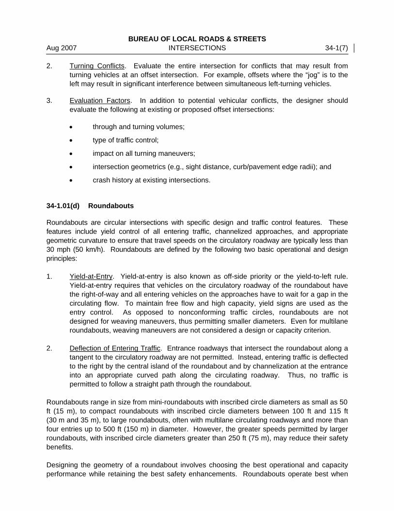
Once the designer has determined the basic right-turning parameters (e.g., design vehicle, amount of allowable encroachment, inside clearance), it will be necessary to select the type of turning design for the curb return or pavement edge that will meet these criteria and will fit the intersection constraints. The simple radius is the easiest to design and construct. However, two-centered or three-centered curves provide a better fit to the transitional turning paths of tractor/semitrailer design vehicles. Figure 34-2A presents the corner radii for simple, two-centered, and three-centered curves. Note that using these curves may require a corner island. Some of the advantages of the two-centered and three-centered curves as compared to the simple radius design include:
BUREAU OF LOCAL ROADS & STREETS Nov 2006 INTERSECTIONS 34-2(3)
RIGHT-TURNING DESIGN CURVES
Figure 34-2A

BUREAU OF LOCAL ROADS & STREETS 34-2(4) INTERSECTIONS Nov 2006 • When accommodating a specific design vehicle, they require less intersection pavement
than a simple radius design, and especially for angles of turn greater than 90°. For large vehicles, a simple radius is often an unreasonable design unless a corner island is used and, in effect, a turning roadway is provided.
• There are less right-of-way impacts at the intersection corners.
• A simple radius results in greater distances for pedestrians to cross the intersection. 34-2.01(f) Curbing
If certain conditions (e.g., drainage requirements, restricted right-of-way, greater delineation, the desire to minimize off-tracking) warrant the use of curbing along the radius return at rural intersections, terminate the curbing at the shoulder edge and transition the curb height as indicated in Figure 34-2B. Use a mountable curb where posted speeds are 50 mph (80 km/h) or greater. 34-2.01(g) Stop Sign Locations
The edge of the stop signs are typically 12 ft (3.6 m) from the edge of the major road traveled way for a rural cross section and a minimum of 2 ft (600 mm) from the face of curb for an urban cross section. They are usually located before the beginning of the radius return, but must be no more than 50 ft (15.25 m) from the edge of the major road traveled way. Stop lines should be located at a point where a road user should stop. Stop sign locations should be checked against the criteria in the ILMUTCD at wide throat intersections. This is especially important where no corner island is used. 34-2.01(h) Turning Template(s)
To determine the preliminary right-turn design, the designer should use the applicable turning template for the selected design vehicle and speed. Check the final intersection design with the applicable turning templates or with a computer simulated turning template program. 34-2.02 Left-Turn Control Radii
For left turns, the motorist generally has a guide at the beginning and end of the turn and an open intersection in the middle. Therefore, the precise alignment of a two-centered or three-centered curve is generally not applicable. Simple curves are typically used for left-turn control radii. Occasionally, a two-centered curve may be desirable to accommodate the off-tracking of large vehicles provided the second curve has a larger radius.

BUREAU OF LOCAL ROADS & STREETS Nov 2006 INTERSECTIONS 34-2(5)
RIGHT-TURN DESIGN
Figure 34-2B

BUREAU OF LOCAL ROADS & STREETS 34-2(6) INTERSECTIONS Nov 2006 The design values for left-turn control radii are usually a function of the design vehicle, angle of intersection, number of lanes, and median widths. For roadways intersecting at approximately 90°, radii of 50 ft to 80 ft (15 m to 24 m) should typically satisfy all controlling factors. If center divisional islands are present, select control radii so that the nose of each divisional island is no closer than 4 ft (1.2 m) nor greater than 10 ft (3.0 m) from the edge of the traveled way of the intersecting highway. The nose location is also affected by the selected nose radii. For additional guidance on median openings and median nose designs, see Section 36-4 of the BDE Manual. Left-turn control radii for dual-lane turning movements should be larger than those indicated for the single-lane design. See Section 34-3.04 for additional design details.

BUREAU OF LOCAL ROADS & STREETS Jan 2006 INTERSECTIONS 34-3(1) 34-3 AUXILIARY TURN LANES
When turning maneuvers for left- and right-turning vehicles occur from the through travel lanes, it typically disrupts the flow of through traffic. This is especially true on high-volume highways. To minimize potential conflicts and to improve the level of service and safety, the use of turn lanes may be warranted for intersections. 34-3.01 Turn Lane Guidelines
34-3.01(a) Right-Turn Lanes
The use of right-turn lanes at intersections can significantly improve operations. Consider using an exclusive right-turn lane in the following situations: • at unsignalized intersections on a high-speed urban or rural highway where traffic
operations indicate the need for right-turn lanes;
• at any intersection where a capacity analysis determines a right-turn lane is necessary to meet the level-of-service criteria;
• at any signalized intersection where the right-turning volume is greater than 150 vehicles per hour and where there is greater than 300 vehicles per hour per lane on the major road;
• for uniformity of intersection design along the highway if other intersections have right-turn lanes;
• at any intersection where the pavement is curved to the left and where the major road curve requires superelevation;
• where a railroad crossing is located close to the intersection and a right-turn lane would be desirable to efficiently move through traffic by moving turning traffic stopped for a train from the through lane.
• at any intersection where the crash experience, existing traffic operations, sight distance restrictions (e.g., intersection beyond a crest vertical curve), or engineering judgment indicates a significant conflict related to right-turning vehicles.
For further guidance, see Figures 36-3A and 36-3B of the BDE Manual. 34-3.01(b) Left-Turn Lanes
The accommodation of left turns is often the critical factor in proper intersection design. Left-turn lanes can significantly improve both the level of service and intersection safety. In general, use an exclusive left-turn lane at all intersections on highways with a median wide enough to accommodate a left-turn lane, regardless of traffic volumes. Consider using an exclusive left-turn lane for the following:

BUREAU OF LOCAL ROADS & STREETS 34-3(2) INTERSECTIONS Jan 2006 • at any signalized intersection where the left-turning volume is equal to or greater than 75
vehicles per hour for a single turn lane or 300 vehicles per hour for a dual turn lane;
• any intersection where a capacity analysis determines a left-turn lane or dual left-turn lanes are necessary to meet the level-of-service criteria;
• for uniformity of intersection design along the highway if other intersections have left-turn lanes (i.e., to satisfy driver expectancy); or
• any intersection where the crash experience, traffic operations, sight distance restrictions (e.g., intersection beyond a crest vertical curve), or engineering judgment indicates a significant conflict related to left-turning vehicles.
For further guidance, see Figures 36-3C through 36-3G of the BDE Manual. 34-3.02 Design of Turn Lanes
Figure 34-3A provides a schematic of auxiliary lanes at an intersection. 34-3.02(a) Turn Lane Widths
The width of the turn lane should be determined relative to the functional class, urban/rural location, and project scope of work (new construction, reconstruction, 3R). Chapters 32 and 33 present the applicable widths for auxiliary lanes based on these criteria. Desirably, turn-lane widths should be 12 ft (3.6 m) or a minimum of 10 ft (3.0 m). The geometric design tables in Chapters 32 and 33 also provide criteria for the applicable shoulder widths adjacent to auxiliary lanes. In general, the minimum shoulder widths adjacent to a turn lane with shoulders should be 4 ft (1.2 m). For curbed sections, the width of the gutter adjacent to the turn lane should be 6 in to 2 ft (150 mm to 600 mm). 34-3.02(b) Turn Lane Lengths
The length of auxiliary lanes will be determined by a combination of its taper length (LT) and storage length (LS). The following discusses the criteria for turn-lane lengths: 1. Taper. The entrance taper into the turn lane may be either a straight or a reverse curve
taper. Always use the straight taper across bridges for ease of construction. Figure 34-3B provides the recommended deceleration distances for straight and reverse curve tapers.

BUREAU OF LOCAL ROADS & STREETS Jan 2006 INTERSECTIONS 34-3(3)
K
ey:
L T
= Ta
per l
engt
h
L D
= D
ecel
erat
ion
leng
th (m
inim
um le
ngth
requ
ired)
L S =
S
tora
ge le
ngth
L AT =
A
ppro
ach
Tape
r Len
gth
⎯
L =
WS
for S
≥ 4
5 m
ph, L
=
mph
45S
for
60WS
2
<
(US
Cus
tom
ary)
L
= 0.
6WS
for S
≥ 7
0 km
/h, L
=
km/h
60S
for
155
WS
2
≤
(Met
ric)
See
Sec
tion
34-3
.02
for a
dditi
onal
gui
danc
e.
Not
e: T
he s
chem
atic
of t
he m
ajor
road
(fre
e flo
win
g) a
lso
appl
ies
to a
ll le
gs o
f a s
igna
lized
inte
rsec
tion.
*
LS +
LT
may
be
grea
ter t
han
L D w
hen
the
capa
city
ana
lysi
s sh
ows
L S >
LD –
LT
(from
Fig
ure
34-3
B).
The
gre
ater
sh
ould
be
used
.
W =
Offs
et in
feet
(US
Cus
tom
ary)
W
= O
ffset
in m
eter
s (M
etric
)
S =
85th
Per
cent
ile S
peed

BUREAU OF LOCAL ROADS & STREETS 34-3(4) INTERSECTIONS Jan 2006
US Customary Stop Speed Reduced to (mph)
Condition 15 20 25 30 35 40 45 50 Design
Speed of Highway
(mph)
Assumed Running Speed (mph)(1)
Length of
Taper (ft)
Total Length of Deceleration Lane Including Taper Length (ft)
30 28 135 235 200 170 140 ⎯ ⎯ ⎯ ⎯ ⎯35 32 155 280 250 210 185 150 ⎯ ⎯ ⎯ ⎯40 36 175 320 295 265 235 185 155 ⎯ ⎯ ⎯45 40 200 385 350 325 295 250 220 ⎯ ⎯ ⎯50 44 220 435 405 385 355 315 285 225 175 ⎯55 48 240 480 455 440 410 380 350 285 235 ⎯60 52 265 530 500 480 460 430 405 350 300 240 65 55 285 570 540 520 500 470 440 390 340 280 70 58 310 615 590 570 550 520 490 440 390 340
Metric Stop Speed Reduced to (km/h)
Condition 20 30 40 50 60 70 80 Design Speed
of Highway (km/h)
Assumed Running Speed
(km/h) (1)
Length of
Taper (m)
Total Length of Deceleration Lane Including Taper Length (m)
50 47 45 75 70 60 45 ⎯ ⎯ ⎯ ⎯60 55 50 95 90 80 65 55 ⎯ ⎯ ⎯70 63 60 110 105 95 85 70 55 ⎯ ⎯80 70 70 130 125 115 100 90 80 55 ⎯90 77 75 145 140 135 120 110 100 75 60
100 85 85 170 165 155 145 135 120 100 85 110 91 90 180 180 170 160 150 140 120 105
Grade Adjustment Factors (2)
Downgrade 6.00% to 5.00% 4.99% to 4.00% 3.99% to 3.01% 3.00% to 0%
1.35 1.28 1.20 1.00Upgrade
0% to 3.00% 3.01% to 3.99% 4.00% to 4.99% 5.00% to 6.00% 1.00 0.90 0.85 0.80
(1) Average running speed assumed for calculations. (2) Ratio from this table multiplied by the length provided above will yield the total deceleration length
adjusted for grade. Adjustment factors apply to all design speeds and are added to the tangent or storage length.
DECELERATION DISTANCES FOR TURNING LANES
Figure 34-3B

BUREAU OF LOCAL ROADS & STREETS Jan 2006 INTERSECTIONS 34-3(5)
Where the highway is on a curved alignment, the taper of the turn lane should be more pronounced than usual to ensure that the through motorists are not inadvertently directed into the turn lane. This is accomplished by shortening the taper length.
2. Storage Length (Signalized Intersections). The storage length (LS) for turn lanes should
be sufficient to store the number of vehicles likely to accumulate in a signal cycle during the design hour. The designer should consider the following in determining the recommended storage lengths for signalized intersections:
a. Determine the distance using the criteria for signalized intersections in the Highway
Capacity Manual or use the following formula: (US Customary)
(Metric)
Where:
G = green time (secs) C = cycle length (secs) DHV = Design Hourly Volume (vph) for turn lane
b. Where right-turns-on-red are permitted or where separate right-turn signal phases are provided, the length of the right-turn lane may be reduced due to less accumulation of turning vehicles. The storage length (LS) needed for a separate right-turn lane is measured from the stop bar for the right-turning roadway; see Figure 34-3A.
c. At signalized intersections, the designer should also consider that entry into right-
and left-turn lanes may be blocked by the signal storage needs of the adjacent through lanes. If this occurs, provide longer lengths of turn lanes.
3. Storage Length (Unsignalized Intersections). To determine the storage length for
unsignalized intersections, assume that the intersection is signalized with a two-phase signal using a 40 to 60 second cycle length. Then use the Highway Capacity Manual to determine the expected storage length.
4. Minimum Storage Length. For all intersections where traffic volumes are too low to
govern, the minimum storage length will be 115 ft (35 m). These minimum lengths may also apply to right-turn lanes at unsignalized intersections if there is little likelihood of the turning vehicle having to wait.
)lanestraffic(#)hourpercycles(#
)25x2()100trucks%1()DHV()C/G1(
)ft(LengthStorage+−
=
)lanestraffic(#)hourpercycles(#
)5.7x2()100trucks%1()DHV()C/G1(
)m(LengthStorage+−
=

BUREAU OF LOCAL ROADS & STREETS 34-3(6) INTERSECTIONS Jan 2006 5. Queue Length of Through Traffic. In addition to the storage for turn-lane volumes, the
length of the turning lane should exceed the calculated queue length in the through travel lane adjacent to the turning lane for the design hour.
6. Clearance Distance of Opposing Left Turns. A minimum 6 ft (1.8 m) clearance between
opposing left-turning vehicles shall be provided for single left-turn lanes. A desirable 10 ft (3 m) should be provided for opposing dual left-turn lanes. See Figure 36-3U of the BDE Manual.
34-3.03 Typical Treatments for Auxiliary Turn Lanes
The following presents typical treatments for right- and left-turn lanes: 1. Right-Turn Lanes. Figure 34-3A illustrates the typical development of an exclusive right-
turn lane using a straight taper. Reverse curves may also be considered for the taper. 2. Channelized Left-Turn Lanes. On divided highways, the design presented in Figure 34-
3A will apply to the development of an exclusive left-turn lane in the median. Figure 34-3C illustrates the typical development for new construction or reconstruction project of a channelized left-turn lane on a rural 2-lane highway. Figure 34-3D illustrates the typical development of channelized left-turn lane on an urban street or for a 3R or safety improvement project on a rural 2-lane highway.
3. By-Pass Area. Figure 34-3E illustrates the typical design for a by-pass area. This is a
relatively inexpensive design to provide for through and left-turn movements at intersections. The by-pass area is appropriate for T-intersections (only unsignalized) where left-turning volumes are light to moderate.
The decision to use either the channelized left-turn (Figures 34-3C and 34-3D) or the by-pass area (Figure 34-3E) will be based on comparative costs, crash history, right-of-way availability, through and turning volumes, design speed, and available sight distance.
4. Offset Turn Lanes. Providing an offset design ensures that opposing left-turning
motorists can see past one another to view oncoming through traffic. Offset left-turn lanes can be either a parallel or taper type. For additional guidance on offset left-turn lanes, see Section 36-3 in the BDE Manual.

BUREAU OF LOCAL ROADS & STREETS Jan 2006 INTERSECTIONS 34-3(7)
FL
USH
CH
AN
NEL
ING
ISLA
ND
AT
AN
ISO
LATE
D, H
IGH
-SPE
ED R
UR
AL
INTE
RSE
CTI
ON
(N
ew C
onst
ruct
ion/
Rec
onst
ruct
ion
Proj
ects
)
Figu
re 3
4-3C
* S
ee S
ectio
n 34
-3.0
2(b)
for s
tora
ge le
ngth
crit
eria
or u
se th
e fo
llow
ing:
US
Cus
tom
ary
Met
ric
Des
ign
Spe
ed
(mph
) S
tora
ge L
engt
h (f
t)
Des
ign
Spe
ed
(km
/h)
Sto
rage
Len
gth
(m)
45
185
70
50
50
215
80
60
55
240
90
70
60
265
100
85

BUREAU OF LOCAL ROADS & STREETS 34-3(8) INTERSECTIONS Jan 2006
APP
RO
ACH
TAP
ER
RAT
ES F
OR
FLU
SH C
HA
NN
ELI
ZATI
ON
Ap
proa
ch T
aper
Rat
es
Left-
Turn
Lan
e Pr
esen
t Po
sted
Spe
ed
(mph
) D
esig
n S
peed
W
iden
ing
on B
oth
Side
s W
iden
ing
All o
n O
ne S
ide
Tape
r R
ate
Min
imum
S
tora
ge L
engt
h*
≥ 50
50
mph
(80
km/h
) 50
:1
40:1
15
:1
115
ft (3
5 m
) 45
45
mph
(70
km/h
) 45
:1
35:1
13
:1
115
ft (3
5 m
) 40
/35
40 m
ph (6
0 km
/h)
40:1
30
:1
11:1
11
5 ft
(35
m)
≤ 30
30
mph
(50
km/h
) 35
:1
25:1
9:
1 11
5 ft
(35
m)
FLU
SH C
HA
NN
ELIZ
ED IS
LAN
DS
AT
ISO
LATE
D R
UR
AL
OR
UR
BA
N IN
TER
SEC
TIO
NS
FOR
SA
FETY
IMPR
OVE
MEN
TS O
R 3
R P
RO
JEC
TS
Figu
re 3
4-3D
*Sto
rage
leng
ths
may
be
incr
ease
d if
nece
ssar
y ba
sed
on S
ectio
n 34
-3.0
2(b)
.

BUREAU OF LOCAL ROADS & STREETS Jan 2006 INTERSECTIONS 34-3(9)
TY
PIC
AL
BY-
PASS
AR
EA O
N A
TW
O-L
AN
E H
IGH
WA
Y
Figu
re 3
4-3E

BUREAU OF LOCAL ROADS & STREETS 34-3(10) INTERSECTIONS Jan 2006 34-3.04 Dual Turn Lanes
34-3.04(a) Guidelines
At intersections with high-turning volumes, dual left- and/or right-turn lanes may be considered. Dual left- and/or right-turn lanes may be considered where: • there is insufficient space to provide the necessary length of a single turn lane because of
restrictive site conditions (e.g., closely spaced intersections);
• based on a capacity analysis, the necessary time for a protected left-turn phase for a single lane becomes unattainable to meet the level-of-service criteria (average delay per vehicle); and/or
• more than 300 vehicles per hour are projected to be turning. Dual turn lanes should only be used with signalization providing a separate turning phase. 34-3.04(b) Design
See Section 36-3 of the BDE Manual for dual turn lane designs.
BUREAU OF LOCAL ROADS & STREETS Jan 2006 INTERSECTIONS 34-4(1) 34-4 ISLANDS
Several of the treatments described in this Chapter require islands within the intersection area. Some intersections, especially those with oblique angle crossings, result in large paved areas that may cause motorists to wander from natural or expected paths and may cause long pedestrian crossings. These movements may result in conflicts and/or unpredictable operations, but could be enhanced by incorporating channelizing islands in the design of the intersection. At rural locations where higher speeds are prevalent, channelizing islands are used in conjunction with left-turn lanes and for turning roadways. In urban areas where speeds generally are lower, but where traffic volumes are generally higher, channelizing islands in conjunction with added lanes are used primarily to increase capacity and safety at the intersection. 34-4.01 Island Types
Islands can be grouped into the following classifications. Most island types serve at least two of these functions: 1. Corner/Directional Islands. Directional or corner triangular islands control and direct
right-turn movements and guide the driver into the proper direction. 2. Channelizing Islands. Center channelizing islands separate opposing traffic flows, alert
the driver to the crossroad ahead, and regulate traffic through an intersection. These islands are often introduced at intersections on undivided highways and are particularly advantageous in controlling left turns at skewed intersections.
3. Refuge Islands. Refuge islands (corner islands or center channelizing islands) may
function to aid and protect pedestrians who cross a wide roadway. These islands may be required for pedestrians where complex signal phasing is used and may permit the use of two-stage crossings. This also may increase the signal efficiency by allowing the time allocated for pedestrian movements to be reduced.
34-4.02 Selection of Island Type
Islands may be some combination of flush, traversable, raised-curb, or turf, and could be triangular or elongated in shape. Selection of an appropriate type of channelizing island should be based on: • traffic characteristics;
• cost considerations;
• urban, suburban, or rural locations;
• degree of access management desired; and

BUREAU OF LOCAL ROADS & STREETS 34-4(2) INTERSECTIONS Jan 2006 • maintenance considerations. The following offers guidance where different types of islands are appropriate. 34-4.02(a) Flush or Traversable Islands
Flush islands, which are delineated by pavement markings (e.g., paint, thermoplastic, epoxy), or traversable islands, which are delineated by M-2 (M-5) curbs, are appropriate for the following situations: • on highways to delineate separate left-turn lanes (flush or traversable);
• in restricted locations where delineation of vehicular path is desirable, but space for larger, raised-curb islands is not available (flush);
• in areas where better long-term visual delineation is needed at night and during inclement weather, but space for raised-curb islands is not available (traversable);
• to separate opposing traffic streams on low-speed urban streets (flush or traversable); and/or
• for temporary channelization during construction (flush). 34-4.02(b) Raised-Curb Islands
Raised-curb islands are at least 4 in (100 mm) high and are appropriate: • on low-speed highways where the primary function is to provide positive separation for
opposing traffic movements;
• at locations requiring positive delineation of vehicular paths (e.g., where a major route turns or at intersections with unusual geometry);
• where the island is intended to prohibit or prevent traffic movements (e.g., wrong-way movements or to manage access within the intersection);
• where a primary or secondary island function is to provide a location for traffic signals, signs, or other fixed objects; and/or
• where a primary function of the island is to provide a pedestrian or bicyclist refuge. Raised-curb islands should be used at rural intersections having the following characteristics: • on the crossroad through an interchange to delineate median crossovers and turn lanes,
and to prevent wrong-way movements, and
• at unusual or complex intersection configurations where higher visibility would promote greater safety and more efficient traffic operations.

BUREAU OF LOCAL ROADS & STREETS Jan 2006 INTERSECTIONS 34-4(3) Where curb and gutter is proposed in high-speed rural areas, only use mountable curbs and consider providing supplemental intersection illumination. In addition, provide prismatic reflectors on the top of curbs to enhance delineation of the island and turn lanes at night. Section 31-1.07 provides further guidance on the types of curbing used for islands. 34-4.02(c) Divisional Islands
Figure 34-4A illustrates a typical curbed divisional island and applicable approach treatment. Guidance for standardized designs based on various design speeds, pavement widths, and island widths are provided in the IDOT publication Transitional Approaches to Channelized Intersections. This document can be obtained from the district or from BDE. For flush-channelizing islands, see Figures 34-3C and 34-3D. 34-4.02(d) Corner Islands
In general, the use of corner islands is discouraged. However, at some intersections, it may be desirable to provide a directional or corner island to direct drivers. This may be especially advantageous where a tractor/semi-trailer is used as the design vehicle and/or at oblique angle crossing intersections. The corner island may also be used for locating traffic control devices. Corner islands may also function as refuge islands to aid and protect pedestrians who cross a wide roadway. Corner islands may be required for pedestrians where complex signal phasing is used, and they may permit the use of two-stage crossings. This may enhance traffic signal efficiency by allowing a reduction in the time allocated for pedestrian movements. These islands must be large enough to accommodate both the signals and pedestrians. The type and size of triangular or corner islands will vary according to the angle of intersection, design vehicle, right-turn operation, and available right-of-way. Figure 34-4B illustrates the typical designs for corner islands. Also consider the following: 1. Island Sides. The sides of the island should not be less than 12 ft (3.6 m) and,
preferably, 15 ft (4.5 m) after rounding the corners. 2. Island Size. The minimum island size for rural areas is 100 ft2 (9.5 m2). For urban
islands, the island area typically should be 75 ft2 (7.0 m2) but not less than 50 ft2 (4.7 m2). The island area includes the concrete median surface and the top of the curb.
3. Flush or Raised-Curb. For proper delineation of corner islands, under all conditions
(e.g., nighttime, rain, fog, snow), the raised-curb design is preferable.

BUREAU OF LOCAL ROADS & STREETS 34-4(4) INTERSECTIONS Jan 2006
TYPI
CA
L C
UR
BED
DIV
ISIO
NA
L IS
LAN
D
Fi
gure
34-
4A
M
=
See
Cha
pter
32
for t
ypic
al m
edia
n w
idth
s W
1 =
Und
ivid
ed a
ppro
ach
wid
th
W2
= D
ivid
ed a
ppro
ach
wid
th
larg
eris
ever
w
hich
m
),(4
.2ft
14or
2WW
13=
desi
rabl
e,
2WW
W2
34
+=
W5
= W
2+
1 ft
(300
mm
)
Not
es:
1.
For
addi
tiona
l de
sign
det
ails
, se
e th
e ID
OT
publ
icat
ion
Tran
sitio
nal A
ppro
ache
s to
Cha
nnel
ized
Inte
rsec
tions
. 2.
Th
e le
ngth
and
sha
pe o
f cha
nnel
izin
g is
land
s de
rive
d fr
om
the
abov
e sk
etch
al
so
may
be
us
ed
as
a gu
ide
for
dete
rmin
ing
a flu
sh, c
ente
r isl
and
desi
gn.

BUREAU OF LOCAL ROADS & STREETS Jan 2006 INTERSECTIONS 34-4(5)
DETAILS OF CORNER ISLANDS Figure 34-4B
Notes: 1. , , - designates a specific corner of
island. 2. Ramp the and noses of curbed corner
islands unless the curb function is for the protection of pedestrians, signals, light standards, or sign truss supports.
3. See the IDOT Highway Standards for
details of ramping noses. 4. All corner radii are to the face of curb at
flowline. 5. * These dimensions are controlled by the
minimum area requirements of the island, whereas “W” is a required dimension.
6. Dimensions in parentheses are in mm
unless otherwise noted.

BUREAU OF LOCAL ROADS & STREETS 34-4(6) INTERSECTIONS Jan 2006 4. Curbing. Only use the M-type curb on corner islands. Also consider the following:
• Use M-6 (M-15) curb on islands that are located adjacent to a highway with
speeds of 45 mph (70 km/h) or less.
• Use M-4 (M-10) curb on islands that are located adjacent to high-speed traffic (i.e., 50 mph (80 km/h) or greater). However, use M-6 (M-15) curb on islands where traffic signal supports, sign truss supports, or any other post with a foundation generally larger than a standard highway sign are present. Note that a stop sign is a standard highway sign.
• Use M-6.06 (M-15.15) or M-4.06 (M-10.15) CC&G on all sides of islands where the island is offset the shoulder width from the edge of the traveled way.
5. Island Offsets. On streets with outside curb and gutter, offset the corner island from the
edge of the traveled way according to Figure 34-4B. In rural areas or for facilities with shoulders, the corner island is offset from the shoulder width, but not greater than 8 ft (2.4 m); see Figure 34-3C. If a right-turn deceleration lane is provided, then offset the corner island at least 8 ft (2.4 m).
6. Location of Stop Signs. The edge of the stop sign should be a minimum of 2 ft (600 mm)
from the face of the curb. 34-4.02(e) Curb Ramps
See Section 41-6 for the application of ADA criteria at intersections. If the crosswalk is placed through an island, give special consideration to the treatment of curb ramps within the raised-curb island. In many cases, the crosswalk can be located directly in front of a divisional island nose without special design provisions or, the island can be shortened sufficiently to permit such location without loss of control for turning vehicles. However, where an island does encroach on the location of a crosswalk, it is usually desirable to depress the entire crosswalk through the island, rather than construct ramps. This is particularly true if the island is less than 100 ft2 (10 m2) or is less than 16 ft (4.8 m) wide. The remaining portion of raised island on either side of the ramp should be of sufficient size to distinguish it as a raised island and for ease of construction. 34-4.03 Median Openings
For the design of median openings, see Section 36-4 of the BDE Manual.

BUREAU OF LOCAL ROADS & STREETS Jan 2006 INTERSECTIONS 34-5(1) 34-5 EXTENSION OF THROUGH LANES BEYOND AN INTERSECTION
At many intersections, traffic volumes drop off considerably after passing a crossroad and, therefore, one lane can be dropped beyond the intersection. However, to fully realize capacity benefits and to provide for a safe merge, the through lanes must be extended beyond the intersection. Figure 34-5A provides preliminary design criteria for determining the distance these lanes should be extended beyond an intersection.

BUREAU OF LOCAL ROADS & STREETS 34-5(2) INTERSECTIONS Jan 2006
US
Cus
tom
ary
Met
ric
Des
ign
Spe
ed
(mph
) D
E (ft
) Ta
per
Leng
th (f
t)
Des
ign
Spe
ed
(km
/h)
DE
(m)
Tape
r Le
ngth
(m)
30
160
180
50
40
54
35
215
245
60
70
74
40
320
320
70
110
96
45
430
540
80
160
162
50
585
600
90
235
180
55
780
660
100
325
198
60
1010
72
0
EXTE
NSI
ON
OF
THR
OU
GH
LA
NE
BEY
ON
D A
N IN
TER
SEC
TIO
N
Figu
re 3
4-5A
Not
es:
1.
DE
is
that
di
stan
ce
requ
ired
by
a ve
hicl
e to
acce
lera
te fr
om a
sto
p to
5 m
ph (
10 k
m/h
) be
low
the
desi
gn s
peed
of t
he h
ighw
ay.
2.
The
tape
r di
stan
ce
is
calc
ulat
ed
usin
g th
efo
llow
ing
equa
tions
and
ass
umin
g a
12 ft
(3.
6 m
)la
ne w
idth
:
L =
WS
for S
≥ 4
5 m
ph
(US
Cus
tom
ary)
L =
WS
2 /60
for S
< 4
5 m
ph
L
= 0.
6 W
S fo
r S ≥
70
km/h
,
(M
etric
)
L =
WS
2 /155
for S
≤ 6
0 km
/h

BUREAU OF LOCAL ROADS & STREETS Jan 2006 INTERSECTIONS 34-6(1) 34-6 INTERSECTION DESIGN NEAR RAILROADS
34-6.01 General Design Considerations
These design guidelines apply to all highway improvement projects where the route is adjacent and parallel to a railroad. Where an at-grade railroad crossing is within 200 ft (60 m) of an intersection, the design should address efforts to keep vehicles from stopping or storing on the tracks. This applies to either signal- or stop-controlled intersections. The following factors should be identified and considered during the planning stages: 1. Clear Storage Distance. Consider alternative designs that provide a minimum distance
of 75 ft (23 m) between the proposed intersection stop line and a point 6 ft (1.8 m) from the closest rail.
2. Space for Vehicular Escape. On the far side of any railroad crossing, consider providing
an escape area for vehicles (e.g., shoulder with curb and gutter behind the shoulder, flush medians, flush-corner islands, right-turn acceleration lanes, improved corner radii).
3. Conflicting Commercial Access. Left-turn vehicular movements that may inhibit the
clearance of queued traffic on the approaches to railroad tracks should be discouraged. If there are existing entrances on the street approach, consider using design features that would eliminate the problems (e.g., left-turn lane, raised-curb median).
4. Restricted Intersection Capacity. During periods of frequent railroad preemption of traffic
signals, consider the effects of reduced traffic flow, lack of progression on the street paralleling the tracks, and traffic backups. Available computer programs should be used to analyze different capacity and operational scenarios and to recommend any countermeasures.
5. Protected Left-Turn Storage. On the street that parallels the tracks, analyze the storage
length needed for left-turns into the side street and across the tracks during preemption of the traffic signals. Without the proper storage length available, this could cause backups into the through lanes.
6. Right-Turn Lanes. On the street that runs parallel to the railroad and where an actuated
NO RIGHT TURN SIGN is proposed in conjunction with railroad preemption, a right-turn lane should be considered for the right-turn movement across the tracks. The auxiliary lane provides a refuge for right-turning vehicles during railroad preemption and eliminates the problem of traffic temporarily blocking the through lanes.
7. Side Street Left-Turn Lane Capacity. On streets that cross railroad tracks, provide
sufficient left-turn storage lengths that will avoid the problem of left turns spilling out onto through lanes and blocking the through lanes.

BUREAU OF LOCAL ROADS & STREETS 34-6(2) INTERSECTIONS Jan 2006 34-6.02 Interconnection Traffic Signal System Design
See Section 39-4 for additional information on traffic signal design. 34-6.03 Signing
See Chapter 39-2 for additional information on traffic signs.