Embed Size (px)
Citation preview

CHAPTER SIX HYDRAULIC SYSTEM AND RELATED COMPONENTS
Hydraulic System Description
The transmission is automatically controlled by a hydraulic control system. The hydraulic control system provides a constant flow of pressurized oil to the torque converter and lubrication circuit. The system also controls the automatic upshifting and downshifting of the planetary geartrain so that the appropriate gear ratio is maintained for the selected gear range and vehicle/engine/axle ratio combination. This provides maximum performance and efficiency under all operating conditions. The Oil Pump The first requirement of the hydraulic system is a source of oil pressure. The engine driven gear type oil pump fulfills this requirement. The oil pump is driven by the torque converter impeller hub; therefore it operates whenever the engine is running, supplying a constant volume of oil to the system. As the pump drive gear is driven by the impeller hub, it acts on or drives the driven gear. At the location where the drive and driven gears come out mesh, a vacuum is created. The oil pump inlet is placed at this location. The oil pump inlet is connected to a reserve of fluid in the transmission oil pan, also known as the sump. Atmospheric pressure acting on the sump helps to push the oil from the sump, thru the filter assembly, and into the pump inlet. At the point of greatest separation between the gears, a crescent is machined into the pump body. The placement of the crescent at this location results in the formation of two chambers between the gear teeth and crescent. Oil from the pump inlet is delivered into the chambers, becoming trapped in the area between the gear teeth and the crescent, and carried to the pump outlet. As the gears pass the crescent they begin to come together again. This coming together results in a pressurized oil volume being squeezed out of the chambers and delivered to the pump outlet. The TH400 oil pump is known as a constant displacement oil pump. This means that as long the pump is turning and there is a volume of oil available to the pump inlet, the pump will deliver oil to the pump outlet, and the oil being delivered to the pump outlet will be proportional to the pump drive speed. Because of the pressure demands placed on the oil pump, it is designed to move a much higher volume of oil than is needed and excess oil is bypassed and returned to the sump.
GM
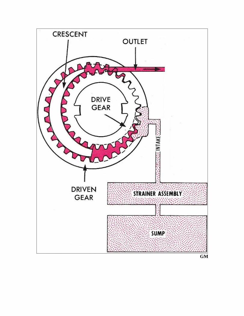
The oil volume delivered to the pump outlet is directed to the pressure regulator valve which creates the operating pressure required by the hydraulic control system. As oil volume demands are met, pressure builds in the system at the outboard or top end of the pressure regulator valve. This causes the valve to move down or stroke against spring pressure, opening a passage which feeds oil into the torque converter. At a specified calibrated pressure, additional movement of the valve occurs, introducing excess fluid into the suction passage and back into the suction side of the pump. If the oil was not returned to the suction side of the pump, excessive oil pressure and component damage would result. Continuous oscillation of the valve maintains the regulated oil pressure required by the hydraulic control system.
GM
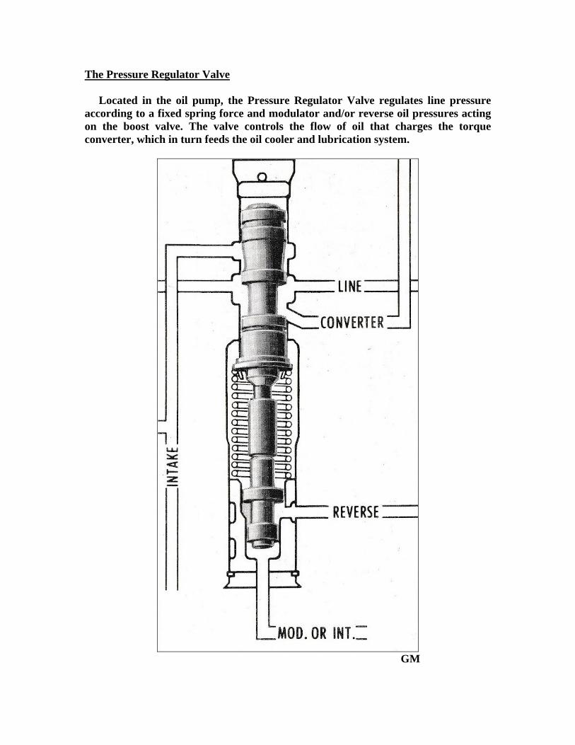
The Pressure Regulator Valve Located in the oil pump, the Pressure Regulator Valve regulates line pressure according to a fixed spring force and modulator and/or reverse oil pressures acting on the boost valve. The valve controls the flow of oil that charges the torque converter, which in turn feeds the oil cooler and lubrication system.
GM

To better understand the function of the pressure regulator valve, consider the valve to have three separate stages of operation. Also keep in mind that during certain modes of operation, all of the hydraulic circuits are not under pressure, but are filled with an oil volume. This allows an instant response from the element or elements associated with that particular circuit as the associated regulating, control, or timing valve opens, charging and pressurizing the circuit. Because of this, a properly functioning transmission usually only needs enough oil volume to make up for the normally occurring internal circuit leaks. During the initial stage of pressure regulation, while various cavities and passages are being filled with oil, there is little resistance to oil flow in the system, therefore pressure does not build. In this mode, the pressure regulator spring holds the pressure regulator valve in the up or closed position. As pressure builds in the circuit, it is fed thru an orifice, and directed to the inboard end of the pressure regulator valve, where it begins to move the valve against the pressure regulator spring. This is the start of the second stage of pressure regulator valve operation. As the valve begins to move it uncovers the converter charge passage. Now, pressurized fluid from the pump flows thru the passage and into the torque converter, charging and pressurizing the converter. Because the converter is always kept full, the second stage of pressure regulation also occurs immediately. Once the converter has become charged, the third and final stage of pressure regulation begins. During the third and final stage of pressure regulation, increased balance oil pressure acting on the inboard end of the pressure regulator valve continues to move the pressure regulator valve against spring pressure, uncovering a passage leading back to the suction or intake side of the pump. The excess oil volume constantly being delivered to the pump outlet is now returned to the suction side of the pump. This is how the system maintains balance. Hydraulic system pressure is now regulated by balancing system pressure against pressure regulator spring force. This means the spring controls the pressure, and the valve automatically adjusts so spring force acting upwards is equal to system pressure acting downward. As system pressure begins to drop, the spring will move the valve up, restricting or even completely blocking off the flow of oil to the sump and/or the torque converter charge passage if necessary, to maintain the regulated pressure. As system pressure begins to rise again, the valve will move down once again supplying the converter and then returning excess volume to the sump.
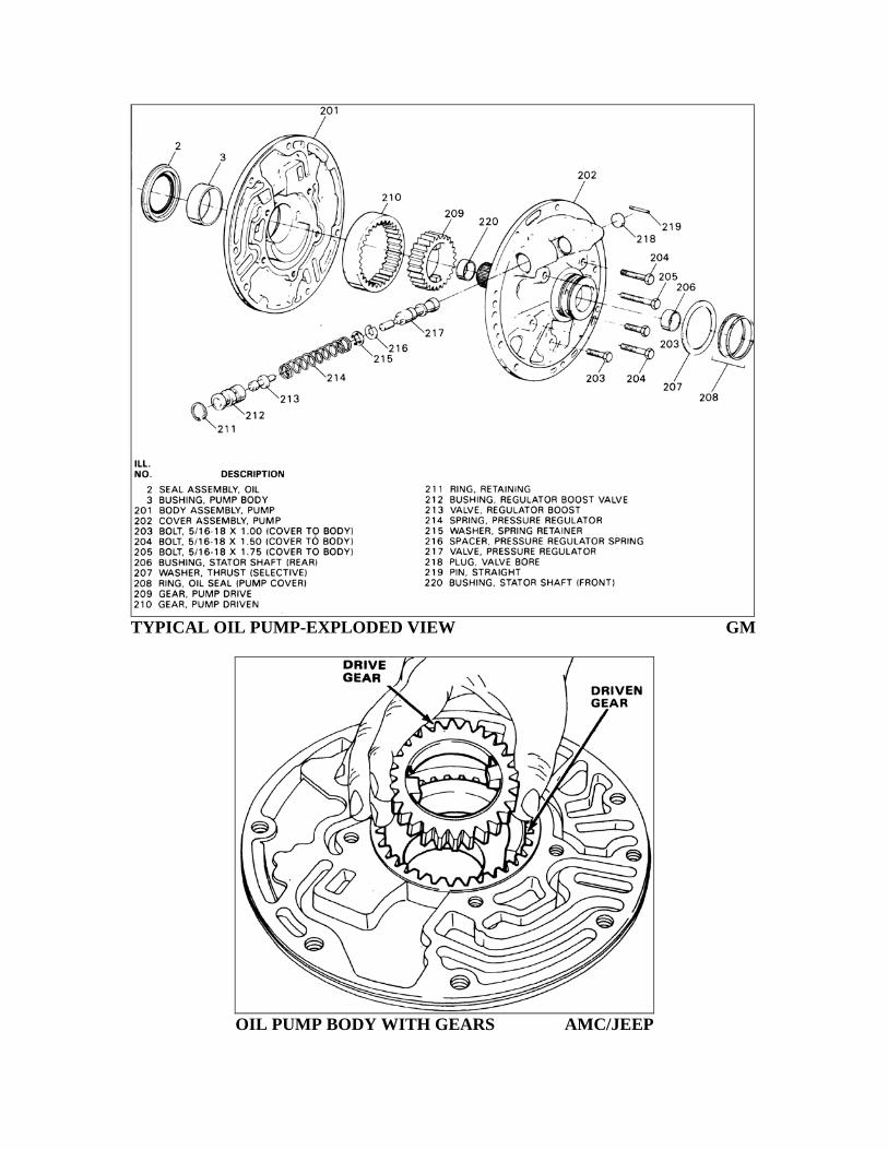
TYPICAL OIL PUMP-EXPLODED VIEW GM
OIL PUMP BODY WITH GEARS AMC/JEEP

TYPICAL OIL PUMP BODY GM TYPICAL OIL PUMP COVER GM
TYPICAL OIL PUMP COVER-EXPLODED VIEW GM
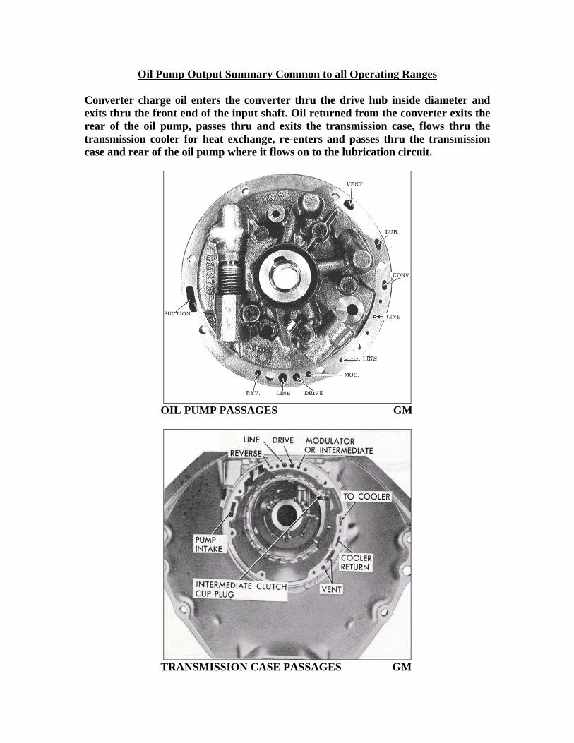
Oil Pump Output Summary Common to all Operating Ranges Converter charge oil enters the converter thru the drive hub inside diameter and exits thru the front end of the input shaft. Oil returned from the converter exits the rear of the oil pump, passes thru and exits the transmission case, flows thru the transmission cooler for heat exchange, re-enters and passes thru the transmission case and rear of the oil pump where it flows on to the lubrication circuit.
OIL PUMP PASSAGES GM
TRANSMISSION CASE PASSAGES GM

Stator Valve -Variable Pitch Models Only Located in the oil pump cover, the stator valve moves to the right or is “downshifted” as soon as the engine is started. This is due to orificed line pressure acting on the outboard end of the valve, holding it in an inoperative or normal position. This same orificed line pressure is fed to the stator solenoid assembly and sealed off by its needle valve during part throttle operation. When the accelerator pedal is depressed all the way to the floor, the detent switch energizes the stator solenoid by supplying it with a 12 volt power source. This in turn exhausts oil from the variable stator piston and the stator blades change from low angle to high angle. When the solenoid is de-energized, converter oil is directed to the stator piston and low angle is obtained.
GM

Hydraulic System Pressure Control The torque capacity of the automatic transmission is directly related to hydraulic system pressure. Increases in hydraulic system pressure are necessary as torque input to the transmission increases to reduce friction element slippage and improve lubrication. To allow the various components and operating systems in the transmission to meet the torque demand requirements, a modulator pressure is used. The pressure regulator valve automatically adjusts line pressure in response to modulator pressure from the modulator valve. Modulator pressure acting on the Modulator/Intermediate land of the boost valve causes the boost valve to apply pressure to the inboard end of the pressure regulator valve. This pressure, which varies according to the torque input to the transmission, combines with pressure regulator valve spring force and the pressure regulator valve then regulates pump output at this higher level, which results in increased hydraulic system pressure.
GM

Vacuum Modulator As previously stated, modulator pressure is used to increase hydraulic system pressure as torque input to the transmission increases. In order for the modulator valve to perform its function of regulating line pressure into modulator pressure in relation to engine torque, it must receive a reference signal indicative of engine load. Because engine vacuum is a good indicator of engine load, it makes for an ideal reference signal (in most cases) to be used for regulating modulator pressure. The signal is plumbed from the engines intake manifold to a Vacuum Modulator Assembly fitted to the transmission case, which controls positioning of the modulator valve in the case bore, and therefore modulator pressure. The assembly consists of an evacuated metal bellows, a diaphragm and springs. These are so arranged that when installed, the bellows and one spring apply a force which acts on the modulator valve. This force acts on the modulator valve so that it increases modulator pressure. Engine vacuum and the other spring act in the opposite direction to decrease modulator pressure. This results in increased line pressure at low engine vacuum and decreased line pressure at high engine vacuum.
GM

Vacuum Modulator Valve Located in the transmission case, the Vacuum Modulator Assembly regulates line pressure to modulator pressure, which varies with engine torque. The valve senses forces created by the vacuum modulator bellows which increase modulator pressure and engine vacuum acting on a diaphragm which decrease modulator pressure.
GM Vacuum Modulator and Shift Scheduling The use of modulator pressure for shift scheduling allows the transmission to “automatically” select the proper gear ratio based on engine load. Modulator pressure, which varies with engine torque, is directed to the 1-2 and 2-3 shift valves, assisting the springs in keeping the valves downshifted. The shift points can now be delayed so that they will take place at a higher vehicle speed and engine RPM with increases in throttle position. If the vacuum modulator system was not used, the shift points would always take place at the same vehicle speed, regardless of throttle position.
VACCUUM MODULATOR AND VALVE GM

The Governor Assembly The vehicle speed signal for the transmission to shift is supplied by the governor assembly. Located in the transmission case, and driven by the output shaft, the governor generates a speed sensitive oil pressure; indicate of vehicle speed, in all forward gear ranges. Governor pressure is directed to the inboard end of the 1-2 and 2-3 shift valves. Governor pressure attempts to “move” or upshift the valves against opposing modulator pressure, spring force, and sometimes detent pressure acting on the valves to keep them in the downshifted position. When road speed and governor pressure is higher than the opposing forces being exerted on the shift valves, an upshift will occur.
GM GM The Governor Assembly and Pressure Regulation The torque converters ability to multiply engine torque tends to decrease as vehicle speed increases and a steady cruise speed is maintained. Under these operating conditions, reductions in modulator pressure are desirable to improve shift quality and operational efficiency, resultant of reduced hydraulic system pressure. To accomplish this, a speed sensitive oil pressure that increases with output shaft or vehicle speed is fed to the modulator valve. This speed sensitive oil pressure also known as governor pressure, acts on the large land of the modulator valve to decrease modulator pressure, and therefore mainline pressure.

Hydraulic Controls The Valve Body
The valve body assembly is the transmissions hydraulic control center, and houses the valvetrain assemblies that control manual and automatic shifting. The valve body is fed information in the form of hydraulic pressure signals relative to the vehicles operating conditions. These pressure signals are indicative of the operating range selected by the driver (manual valve position), engine load (modulator and detent pressures), and vehicle speed (governor pressure). These signals are then interfaced with the various valvetrains contained within the assembly, which in turn control the flow of oil to the various accumulators, servos and friction elements which control automatic shifting. The valve trains are calibrated so that shift scheduling promotes maximum durability and operating efficiency. In general, the oil passages in the valve body run from the left side of the transmission to the right side of the transmission in a manner that allows them to interface with the oil passages in the transmission case, most of which run from the front of the transmission to the back of the transmission.
VALVE BODY PASSAGES GM
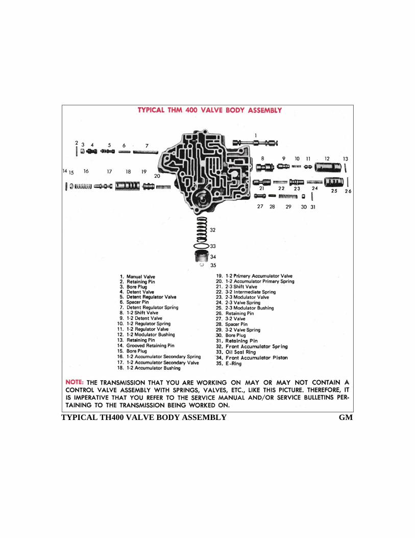
TYPICAL TH400 VALVE BODY ASSEMBLY GM
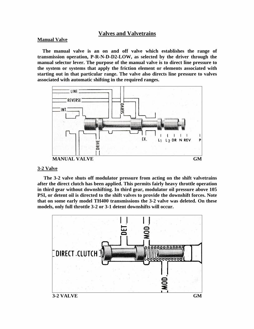
Valves and Valvetrains Manual Valve The manual valve is an on and off valve which establishes the range of transmission operation, P-R-N-D-D2-LOW, as selected by the driver through the manual selector lever. The purpose of the manual valve is to direct line pressure to the system or systems that apply the friction element or elements associated with starting out in that particular range. The valve also directs line pressure to valves associated with automatic shifting in the required ranges.
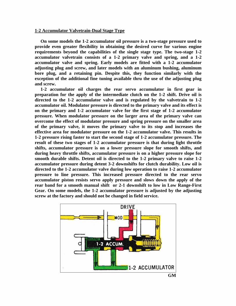
MANUAL VALVE GM 3-2 Valve The 3-2 valve shuts off modulator pressure from acting on the shift valvetrains after the direct clutch has been applied. This permits fairly heavy throttle operation in third gear without downshifting. In third gear, modulator oil pressure above 105 PSI, or detent oil is directed to the shift valves to provide the downshift forces. Note that on some early model TH400 transmissions the 3-2 valve was deleted. On these models, only full throttle 3-2 or 3-1 detent downshifts will occur.
3-2 VALVE GM

1-2 Shift Valvetrain “TYPE A” Located in the control valve body, the 1-2 shift valvetrain consists of a 1-2 shift valve, a 1-2 detent valve and a 1-2 regulator valve. The 1-2 shift valve controls the oil pressure that causes the transmission to shift from 1-2 or 2-1. Its operation is controlled by governor, detent, modulator, and low range oil pressures and a spring force. Governor pressure moves the valve for the 1-2 upshift. Low oil pressure is directed against one valve land on the shift valve for the purpose of preventing a downshift over 40 mph when selector lever is placed in the LOW range. The 1-2 detent valve senses regulated modulator pressure, tending to hold the 1-2 shift valve in the downshifted position and provides an area for detent oil pressure for detent 2-1 downshifts. The 1-2 regulator valve regulates modulator pressure to a pressure proportional to modulator pressure, tending to hold the 1-2 shift valve in the downshifted position and also provides an additional area for detent oil pressure for detent 2-1 downshifts.
1-2 SHIFT VALVETRAIN “TYPE A” GM

1-2 Shift Valvetrain “TYPE B” Located in the control valve body, the 1-2 shift valvetrain consists of a 1-2 shift valve and a 1-2 modulator valve. The 1-2 shift valve controls the oil pressure that causes the transmission to shift from 1-2 or 2-1. Its operation is controlled by governor, detent, modulator, and low range oil pressures and a spring force. Governor pressure moves the valve for the 1-2 upshift. Low oil pressure is directed against one valve land on the shift valve for the purpose of preventing a downshift over 40 mph when selector lever is placed in LOW range. The 1-2 modulator valve senses regulated modulator pressure, tending to hold the 1-2 shift valve in the downshifted position and provides an area for detent oil pressure for detent 2-1 downshifts.
1-2 SHIFT VALVETRAIN “TYPE B” GM

2-3 Shift Valvetrain Located in the control valve body, the 2-3 shift valvetrain consists of a 2-3 shift valve and a 2-3 modulator valve. The 2-3 shift valve controls the oil pressure that causes the transmission to shift from 2-3 or 3-2. Its operation is controlled by modulator, intermediate, governor and detent oil pressure as well as a spring force. The 2-3 modulator valve senses modulator pressure to apply a variable force proportional to modulator pressure which tends to hold the 2-3 shift valve in the downshifted position. Governor pressure moves the valve for the 2-3 upshift.
2-3 SHIFT VALVETRAIN GM

1-2 Accumulator Valvetrain-Single Stage Type 1-2 accumulator oil pressure is used to obtain greater flexibility in attaining the desired 1-2 shift curve for various engine requirements. The accumulator valvetrain consists of a 1-2 accumulator valve and either one or two springs. Early models are fitted with a 1-2 accumulator adjusting plug and screw, and later models with an aluminum bore plug and retaining pin. Despite this, they function similarly with the exception of the additional fine tuning available thru the use of the adjusting plug and screw.
1-2 ACCUMULATOR VALVETRAIN GM 1-2 accumulator oil charges the rear servo accumulator, in first gear, in preparation for the apply of the intermediate clutch on the 1-2 shift. Drive oil is directed to the 1-2 accumulator valve and is regulated by the accumulator valvetrain to become 1-2 accumulator oil. The accumulator oil pressure is varied by modulator, detent, and LOW range oil pressures acting on its valvetrain. Modulator pressure directed to the 1-2 accumulator valve, results in 1-2 accumulator pressure being engine torque conscious and therefore, adjusts for smooth, durable shifts according to engine torque output. Detent oil, directed to the 1-2 accumulator valve, raises accumulator pressure during detent 1-2 shifts for clutch durability. LOW range oil is directed to the 1-2 accumulator valve during LOW range operation to raise accumulator pressure to line pressure. This increased pressure directed to the rear servo accumulator piston, resists servo apply pressure and slows down the apply of the rear band. This results in smooth manual downshifts to the LOW range as well as smooth automatic 2-1 downshifts in the LOW range. On some models, the 1-2 accumulator pressure adjusting screw is factory adjusted and should not be changed in field service unless 1-2 or 2-1 shift concerns exist.
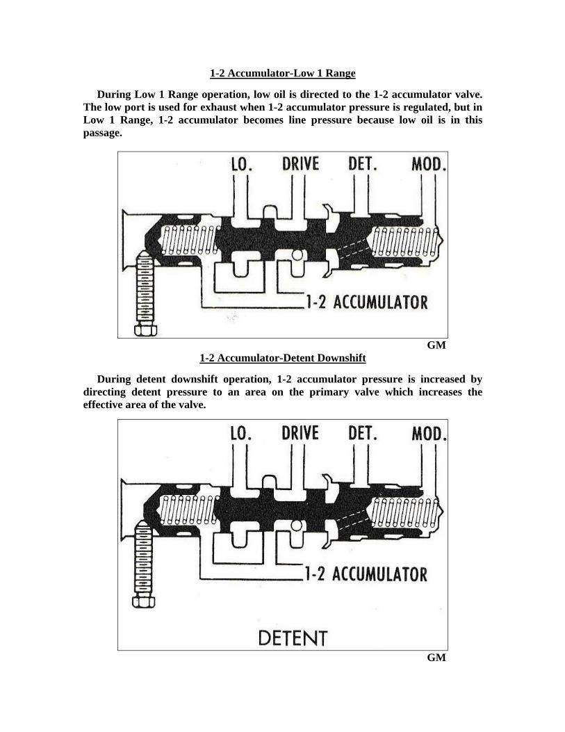
1-2 Accumulator Valvetrain-Dual Stage Type On some models the 1-2 accumulator oil pressure is a two-stage pressure used to provide even greater flexibility in obtaining the desired curve for various engine requirements beyond the capabilities of the single stage type. The two-stage 1-2 accumulator valvetrain consists of a 1-2 primary valve and spring, and a 1-2 accumulator valve and spring. Early models are fitted with a 1-2 accumulator adjusting plug and screw, and later models with an aluminum bushing, aluminum bore plug, and a retaining pin. Despite this, they function similarly with the exception of the additional fine tuning available thru the use of the adjusting plug and screw. 1-2 accumulator oil charges the rear servo accumulator in first gear in preparation for the apply of the intermediate clutch on the 1-2 shift. Drive oil is directed to the 1-2 accumulator valve and is regulated by the valvetrain to 1-2 accumulator oil. Modulator pressure is directed to the primary valve and its effect is on the primary and 1-2 accumulator valve for the first stage of 1-2 accumulator pressure. When modulator pressure on the larger area of the primary valve can overcome the effect of modulator pressure and spring pressure on the smaller area of the primary valve, it moves the primary valve to its stop and increases the effective area for modulator pressure on the 1-2 accumulator valve. This results in 1-2 pressure rising faster to start the second stage of 1-2 accumulator pressure. The result of these two stages of 1-2 accumulator pressure is that during light throttle shifts, accumulator pressure is on a lower pressure slope for smooth shifts, and during heavy throttle shifts, accumulator pressure is on a higher pressure slope for smooth durable shifts. Detent oil is directed to the 1-2 primary valve to raise 1-2 accumulator pressure during detent 3-2 downshifts for clutch durability. Low oil is directed to the 1-2 accumulator valve during low operation to raise 1-2 accumulator pressure to line pressure. This increased pressure directed to the rear servo accumulator piston resists servo apply pressure and slows down the apply of the rear band for a smooth manual shift or 2-1 downshift to low in Low Range-First Gear. On some models, the 1-2 accumulator pressure is adjusted by the adjusting screw at the factory and should not be changed in field service.
GM

1-2 Accumulator-First Stage Drive oil is regulated to 1-2 accumulator pressure by the effect of modulator oil and spring pressure on the primary and 1-2 accumulator valves and 1-2 accumulator oil and spring pressure on the 1-2 accumulator valve. The Low passage is used for exhaust. In the first stage of regulation the primary valve is grounded to the 1-2 accumulator valve, which results in a low slope of 1-2 accumulator pressure.
GM
1-2 Accumulator-Second Stage When modulator pressure on the larger area of the primary valve can overcome modulator oil and spring pressure on the smaller end of the primary valve, it grounds the primary valve in the valve bore, and eliminates the effect of the modulator spring, resulting in a higher slope.
GM
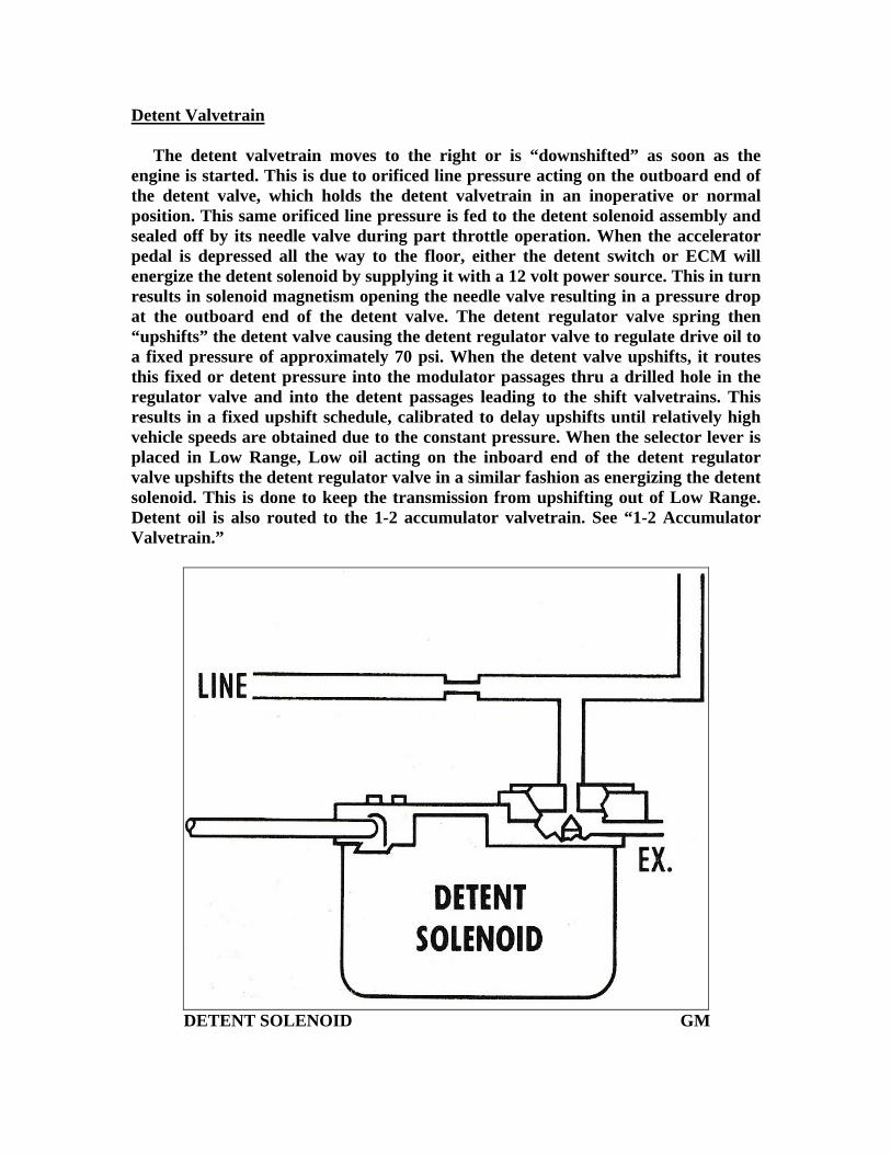
1-2 Accumulator-Low 1 Range During Low 1 Range operation, low oil is directed to the 1-2 accumulator valve. The low port is used for exhaust when 1-2 accumulator pressure is regulated, but in Low 1 Range, 1-2 accumulator becomes line pressure because low oil is in this passage.
GM
1-2 Accumulator-Detent Downshift During detent downshift operation, 1-2 accumulator pressure is increased by directing detent pressure to an area on the primary valve which increases the effective area of the valve.
GM
Detent Valvetrain The detent valvetrain moves to the right or is “downshifted” as soon as the engine is started. This is due to orificed line pressure acting on the outboard end of the detent valve, which holds the detent valvetrain in an inoperative or normal position. This same orificed line pressure is fed to the detent solenoid assembly and sealed off by its needle valve during part throttle operation. When the accelerator pedal is depressed all the way to the floor, either the detent switch or ECM will energize the detent solenoid by supplying it with a 12 volt power source. This in turn results in solenoid magnetism opening the needle valve resulting in a pressure drop at the outboard end of the detent valve. The detent regulator valve spring then “upshifts” the detent valve causing the detent regulator valve to regulate drive oil to a fixed pressure of approximately 70 psi. When the detent valve upshifts, it routes this fixed or detent pressure into the modulator passages thru a drilled hole in the regulator valve and into the detent passages leading to the shift valvetrains. This results in a fixed upshift schedule, calibrated to delay upshifts until relatively high vehicle speeds are obtained due to the constant pressure. When the selector lever is placed in Low Range, Low oil acting on the inboard end of the detent regulator valve upshifts the detent regulator valve in a similar fashion as energizing the detent solenoid. This is done to keep the transmission from upshifting out of Low Range. Detent oil is also routed to the 1-2 accumulator valvetrain. See “1-2 Accumulator Valvetrain.”
DETENT SOLENOID GM

DETENT VALVETRAIN GM
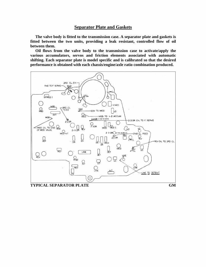
Separator Plate and Gaskets The valve body is fitted to the transmission case. A separator plate and gaskets is fitted between the two units, providing a leak resistant, controlled flow of oil between them. Oil flows from the valve body to the transmission case to activate/apply the various accumulators, servos and friction elements associated with automatic shifting. Each separator plate is model specific and is calibrated so that the desired performance is obtained with each chassis/engine/axle ratio combination produced.
TYPICAL SEPARATOR PLATE GM

Transmission Case and Checkballs Checkballs are installed in the transmission case, and act on the separator plate. Checkballs serve two primary functions in the TH400:
A. Checkballs are used to control the flow of oil to a clutch or band so that the desired apply and release rates for that particular friction element can be obtained. This is of course in concert with other hydraulic and mechanical factors/components present in the circuit which are relative to the friction elements apply and release rates. This allows the fine tuning of the upshift and downshift feel, as well as matching the capacity of the friction element to the chassis/engine/axle ratio combination in use. This is of significant importance during the application of the intermediate clutch pack. During application, the intermediate clutch pack grounds the one way clutch assembly. Due to the anti-rotation of the direct clutch housing in first gear, which approaches three times engine rpm, the assembly is very sensitive to shock loading when the housing is suddenly stopped. Failure to control the apply rate of the intermediate clutch can result in failure of the one way clutch assembly and /or outer race, as well as the intermediate clutch backing plate locating lugs in the transmission case.
B. Checkballs are used to separate two independent oil supply circuits to a common element. For example, the rear servo assembly can be applied in either Reverse or Manual Low range. Both ranges have an independent oil supply circuit that leads to the rear servo apply port. A means of shutting off the inactive oil supply circuit from the active oil supply circuit must be implemented. If the inactive oil supply circuit is not shut off/closed, the active oil supply would use the inactive oil supply circuit as an exhaust to the sump. This would result in a loss of rear servo apply pressure in either Reverse or Manual Low range, causing either no reverse or slipping in reverse, or no engine braking in manual low.
TYPICAL “FLOW CONTROL”CHECKBALL CIRCUIT GM
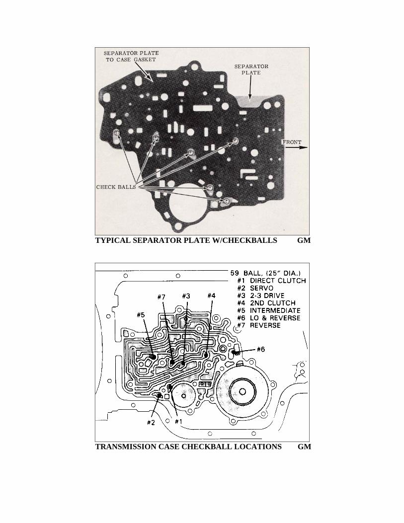
TYPICAL SEPARATOR PLATE W/CHECKBALLS GM
TRANSMISSION CASE CHECKBALL LOCATIONS GM
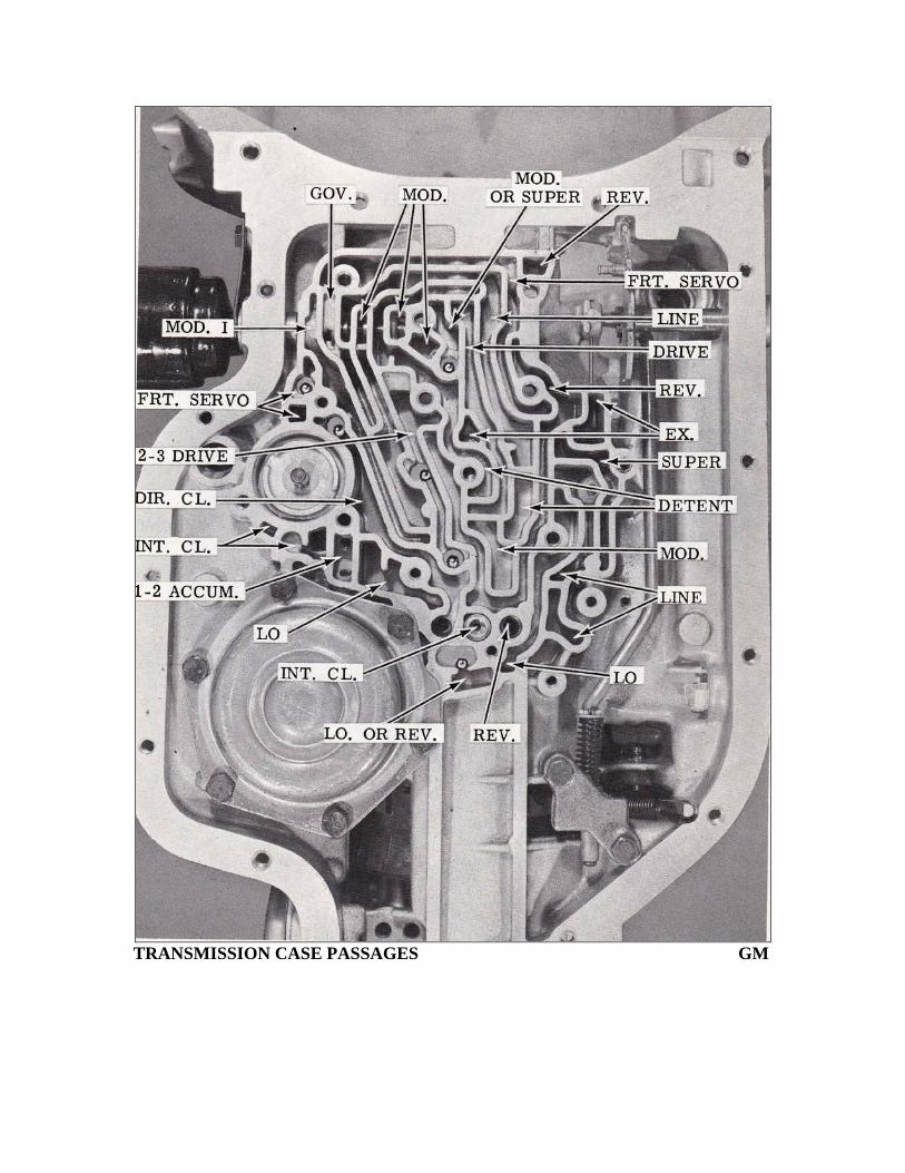
TRANSMISSION CASE PASSAGES GM

Individual Checkballs and Their Function #1 Checkball-Direct Clutch The #1 checkball is used to control the flow of direct clutch exhaust during a 3-2 downshift. Some models do not utilize a #1 checkball. #2 Checkball-Front Servo Release The #2 checkball is used to control the flow of RND oil to the release side of the front servo and provide a rapid release during the exhausting of the circuit. #3 Checkball- Front Servo Apply The #3 checkball is used to control the flow of intermediate clutch oil to the apply side of the front servo and provide a rapid release during the exhausting of the circuit. #4-Checkball-Intermediate Clutch Apply The #4 checkball is used to control the flow of intermediate clutch oil to apply the intermediate clutch and provide a rapid release during the exhausting of the circuit. #5-Checkball-Intermediate The #5 checkball is used to separate the modulator and intermediate passages to the boost valve assembly. #6 Checkball-Low and Reverse The #6 checkball is used to separate the low and reverse passages to the rear servo assembly. #7 Checkball- Reverse The #7 checkball was introduced for the 1988 model year as part of a reverse engagement package on some models. The #7 checkball is used to control the flow of direct clutch oil to apply the direct clutch in reverse and provide a rapid release during the exhausting of the circuit.

Front and Rear Servos The Front Servo
The front servo serves these functions:
A. Intermediate clutch oil applies the front servo to apply the front band in second gear- Low and Low 2 Ranges.
B. During a 2-3 shift upshift, direct clutch oil utilizes the servo and accumulator pistons as the accumulator for direct clutch apply.
GM
Rear Servo and Accumulator Assembly
The rear servo and accumulator assembly serves these functions.
A. The band apply piston provides the force to apply the rear band in both Reverse and Low Range.
B. The accumulator piston, in conjunction with 1-2 accumulator oil, provide the accumulator action for the apply of the intermediate clutch.
GM