Embed Size (px)
Citation preview
P1: FCH
GB093-01 GB093-Miller August 31, 2004 19:10 Char Count= 0
Chapter 1Location of Structure on SiteA number of factors affect the location of a structure on a site,as well as the type of building that may be erected. Once the site ischosen, different methods may be used to create the plan for buildingthe structure. Required documentation to attain final approval ofthe building includes the plot plan, the Certified Plot Plan, and theCertificate of Occupancy.
Basic ConditionsA number of conditions determine what kind of building may beerected, as well as where on the lot it may be located, including thefollowing:
� Covenants� Zoning ordinances� Well location� Septic system location� Corner lots� Nonconforming lots� Natural grades and contours
CovenantsCovenants are legally binding regulations that may, for example,limit the size or set the minimum size of a house, prohibit utilitybuildings, or ban rooftop television antennas. Because covenants areprivate agreements, they are not enforceable by local government.A lot may be zoned for duplexes, but the covenants may allow onlysingle-family residences. When buying lots, check the deed or withthe city building department to see if there are covenants.
Zoning OrdinancesZoning regulates how much of the site may be occupied by a build-ing, restricts the minimum size of a dwelling, and limits its height.Zoning also establishes setbacks, which are the minimum distancespermitted between a building and the property lines around it. Be-cause setbacks can vary according to soil conditions, you shouldconfirm setback requirements with the local zoning administrator.
Wells and Septic SystemsBuilding lots requiring a septic system and well can make locatingthe house difficult. An approved septic system design shows the
1
COPYRIG
HTED M
ATERIAL

P1: FCH
GB093-01 GB093-Miller August 31, 2004 19:10 Char Count= 0
2 Chapter 1
location of proposed house, well, septic system, and required safetyzone distances. A typical safety zone may require that a house withfooting drains be located 25 feet from the septic tank and 35 feetfrom the leach field, and that the well be located 75 feet from theseptic tank. If footing drains are not required, the house can be5 feet and 10 feet, respectively, from the tank and leach field. Welldistance is constant.
A buyer of a lot with approved septic designs may not like thelocation of the house and want it changed. Lot size, shape, natu-ral grades, contours, and safety zone requirements may not allowmoving the house. If safety zone distances can be maintained, houserelocation may be approved. Otherwise, another soil percolation(perk test) must be performed and a new design submitted to thestate for approval. The well can be relocated, but some zoning or-dinances do not allow it in the front yard setback.
Corner LotsCorner lots front two streets. They have two front yard setbacks, arear yard setback, but no side yard setback. Which street the housefaces is the builder’s or buyer’s decision, but local government subdi-vision regulations may prohibit two driveways. Because of the twofront yard setbacks, the lot area within the setbacks is somewhat re-duced. If a septic system and well are required, fitting all of this ona smaller lot is tricky, and will be more difficult if wells and swim-ming pools are prohibited in the front yard setback. Many stateslimit how close the leach field can be to the property line. Local or-dinances also may prevent locating the leach field between the sideyard setbacks and the property line.
Designing the septic system requires digging deep-hole test pitsto examine the soil at various depths to locate the seasonable highwater table (SHWT); to determine the presence or absence of water,ledge, stumps, or debris; and to obtain a soil profile. This informa-tion is recorded on the design plan. This data tells how expensiveexcavation may be and how far down the bottom of the basementshould be. On lots with town sewers, to find the depth of water tableand if ledge is present, dig test holes 8 feet to 10 feet deep where thehouse will be located.
Nonconforming LotsNonconforming (grandfathered) lots are those whose area, frontage,depth, or setbacks do not conform to present zoning ordinances.Getting a building permit may be difficult. As with smaller cornerlots, trying to fit house, well, septic system, and safety zone withinthe setbacks can be very demanding (if not impossible).

P1: FCH
GB093-01 GB093-Miller August 31, 2004 19:10 Char Count= 0
Location of Structure on Site 3
Natural Grades and ContoursNatural grades and contours also affect location of septic systems,houses, wells, and driveways. Is the lot on a hill, on flat land, or ina valley? What are the soil types and how do they affect site use? Isthe soil-bearing capacity adequate for the proposed construction?
Heavily treed lots are a mixed blessing. Trees provide shade onthe south and west and act as a buffer on the north. After the siteis cleared of trees, where do you dispose of the stumps? If the localdump will not accept them, who will? Does the local conservationcommission allow them to be buried on the lot?
If the house is built on raised fill, what effect will this have ondrainage of water toward abutter’s property? Are there stagnantponds, marshes, or other breeding sources of mosquitoes? If wet-lands exist, is enough land left for building after subtracting thewetlands area from the total lot area?
Staking Out House LocationWith site analysis completed and a specific location chosen, thenext step is to locate each corner and lay out the building lines.Staking a building on a level rectangular lot is simple. On a slop-ing, odd-shaped lot, it is more difficult. In both cases, accuracy isimportant. Following are two methods of staking out the houselocation:
� Measuring from a known reference line� Using a transit-level
Staking Out from a Known Reference LineWhen a building is to be erected parallel to the property line, theproperty line is a known, identifiable line. The property line becomesthe reference point and makes a builder’s level unnecessary. First,ensure that corner markers or monuments (usually granite in thefront and iron pipes or pins in the rear) are in place. If markers aremissing, call the surveyor. From the plot plan (Figure 1-1), find thesetback distances.
CautionTaping is more difficult than it seems to be. The distances to bemeasured are horizontal, not sloped distances. If the lot is slopedand you are downhill from the reference marker, use plumb bobsand hand levels to keep the tape level. On ground that is levellay the tape on the ground, rather than supporting each end. Onsloping lots, pull hard on the tape to remove most of the sags. Inthis instance, a steel tape is best.

P1: FCH
GB093-01 GB093-Miller August 31, 2004 19:10 Char Count= 0
4 Chapter 1
DUE NORTH 160.0C DR. BAR
END REARYARD
SETBACK
45' 0"
79' 0"
R. BAREND
S 90° 00' 00" W
S 88° 20' 30" E
50' 0"
46' 0"
26' 0"
60' 0"
20' 0"20' 0"30' 0"
FRONT
YARDSETBACK
207.0 220.0
GB
A
BGBS .04° 49' .02" W/45.0
BATES DRIVENE
Figure 1-1 Plot plan showing property lines and corner markers, lo-cated and identified, house location, and setback lines.
To stake out, refer to Figure 1-2 and proceed as follows:
1. Prepare 10 or more 3-foot long stakes by drawing diagonalson the flat head to locate the center, and drive a nail where thelines cross.
2. Locate the right rear property marker D. Measure 45 feet-0inches from D toward the front granite marker B. This is therear yard setback distance. Drive a stake. This stake is markedE1 in Figure 1-2.
3. Locate the left rear property marker. Measure 45 feet-0 inchesfrom D toward the front granite marker A. This stake ismarked E2.

P1: FCH
GB093-01 GB093-Miller August 31, 2004 19:10 Char Count= 0
Location of Structure on Site 5
DUE NORTH 160.0
R. BAREND
R. BAREND
C D
45' 0"
REAR YARD SETBACKE2
F2 F1
E1
S 90° 00' 00" W
S .04° 49' .02" W
S 88° 20' 30" E
H2ND CORNER
J4TH CORNER
I3RD CORNER
G1ST CORNER
SIDE YARDSETBACKS
20' 0"
30' 0"
207.0
220.0
20' 0"
FRONT YARD SETBACK
A
BBATES DRIVEN
GB
GB
Figure 1-2 Steps 1 to 8. Laying-out with a transit level.
4. Stretch a line tightly across the lot between stakes E1 and E2to locate the rear yard setback line. Next, the two rear cornersof the house must be located. The plan shows the house is34 feet from the rear yard setback line. From the left stakeE2 measure 34 feet-0 inches toward the front and drive a stake,F2. From the right stake E1 measure 34 feet-0 inches towardthe front and drive a stake, F1. Consult the plot plan to seehow far in the house corners will be from the left and rightproperty lines.
5. From the left stake F2 measure in 50 feet-0 inches to the right,and drive a stake. This is the left rear corner of the house.From the right stake F1 measure in 60 feet-0 inches to theleft, and drive a stake. This is the right rear corner of the

P1: FCH
GB093-01 GB093-Miller August 31, 2004 19:10 Char Count= 0
6 Chapter 1
house. The distance between these two stakes is the length ofthe rear of the building. Confirm that this distance, 46 feet-0inches, agrees with the length given on the plot plan (Fig-ure 1-1).
6. Get the depth of the house from the plot plan. From the leftrear corner stake measure 26 feet-0 inches toward the frontyard, and drive a stake. This is the left front corner of thehouse. From the right rear corner stake measure 26 feet-0inches toward the front yard, and drive a stake. This is theright front corner of the house. The distance between thesetwo stakes is the length of the front of the building. Confirmthat it agrees with the length shown on the plot plan (Fig-ure 1-1). If the property lines form a 90-degree angle at thecorners, the left and right sides of the building should be par-allel with the left and right property lines. The front and rearlengths should be parallel with the front and rear propertylines.
On a nonrectangular lot, where the corners do not form a90-degree angle, this method will not work because the buildinglines will not be parallel to the property lines. The setback linesshould be staked out, and the corner of the building closest to theproperty line, but within the setback, should be located. The build-ing should be staked out from this point, with a dumpy level ortransit level, using the method described in the “Batter Boards andOffset Stake” section later in this chapter.
Laying Out with a Transit LevelThere are two types of surveyor’s levels in common use: the auto-matic optical level (also known as a dumpy level or builder’s level,as shown in Figure 1-3) and the transit level (Figure 1-4). The opti-cal level is fixed horizontally and cannot be used to measure angles.The transit level can be moved horizontally or vertically, and canbe used to measure vertical angles, run straight lines, and deter-mine whether a column, building corner, or any vertical structureis plumb. The laser level (Figure 1-5), common in commercial con-struction, is slowly replacing the transit level in residential construc-tion.
To lay out the building using transit level, a reference point, orbenchmark, is needed. The rear right corner marker serves this pur-pose. To lay out the building using a transit level, refer to Figure 1-3and follow these steps:

P1: FCH
GB093-01 GB093-Miller August 31, 2004 19:10 Char Count= 0
Location of Structure on Site 7
Figure 1-3 Automatic level. (Courtesy The Lietz Company)
Figure 1-4 Transit level. (Courtesy The Lietz Company)
P1: FCH
GB093-01 GB093-Miller August 31, 2004 19:10 Char Count= 0
8 Chapter 1
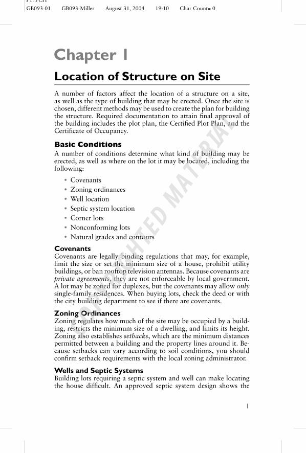
Figure 1-5 Laser level. (Courtesy The Lietz Company)
CautionWhen setting up the transit over a marker on a slope, put twoof the tripod legs on the downhill side, and the other leg on theuphill side. Locate the top of the tripod as close as possible to themarker.
1. Level and plumb the transit over marker D. Sight down to theopposite corner marker B.
2. The rear yard setback is 45 feet-0 inches. Measure 45 feet-0inches from marker D. Take one of the previously preparedstakes, align the 45 feet-0 inches mark on the tape measurewith the center of the stake. Release the transit telescope, andlower it until the crosshairs, the nail in the center of the stake,and the 45 feet-0 inches mark agree. This is point E .

P1: FCH
GB093-01 GB093-Miller August 31, 2004 19:10 Char Count= 0
Location of Structure on Site 9
3. The house is 34 feet from the rear setback line. From pointE1 measure 34 feet-0 inches. While holding the tape 34 feet-0inches mark at the nail in the center of the stake, raise thetelescope until the crosshairs are exactly on the 34 feet-0 inchestape mark, and drive the stake. This is point F1.
4. Move the transit to mark F1, level and plumb it, and sightback on marker B. Now turn the telescope 90 degrees to theright.
5. The distance from the property line (Figure 1-1) to the rightside of the building is 60 feet-0 inches. From mark F1 measure60 feet-0 inches and drive a stake. Lower the telescope untilthe horizontal crosshair is on the 60 feet-0 inches mark on thetape. This is the first corner of the building, and it is point G.
6. Move the transit to point G, and level and plumb it. Mea-sure 46 feet-0 inches from point G. This is the length of thebuilding. Now raise the telescope until the horizontal crosshaircoincides with the 46 feet-0 inches mark on the tape. Align thecenter of the stake with the 46 feet-0 inches mark on the tape,and drive the stake. Point H has been located and is the secondcorner of the building.
7. With the transit still over point G, turn it 90 degrees to the left.Measure 26 feet-0 inches from point G. Then, lower the tele-scope until the horizontal crosshair is on the 26 feet-0 inchesmark on the tape. Align the nail with the 26 feet-0 inches tapemark, and drive the stake. Point I is established and is thethird corner of the building.
8. Level and plumb the transit over point I , and sight back topoint G. Rotate the telescope 90 degrees to the left. Frompoint I measure 46 feet-0 inches. Lower the telescope untilthe horizontal crosshair is on the 46 feet-0 inches mark on thetape. Align the center of the stake with the 46 feet-0 inchesmark on the tape, and drive the stake. This, the fourth andfinal corner of the building, is point J .
Batter Boards and Offset StakesNow that the building corners have been established, building linesmust be set up to mark the boundaries of the building. Batterboards are used to permanently mark the excavation and founda-tion lines. The forms for the foundation walls will be set to thesebuilding lines. The batter boards should be installed 4 to 6 feet backfrom the building corner stakes. Suspend a plumb bob over the

P1: FCH
GB093-01 GB093-Miller August 31, 2004 19:10 Char Count= 0
10 Chapter 1
building corner stakes to exactly locate the lines over the cornerstakes. When all the building lines are in place, ensure that the mea-surements between the lines agree with the measurements shown onthe blueprints. Measure the two diagonals of the batter board linesto ensure that the building lines are square.
Offset stakes (an alternative to batter boards) are stakes that areoffset several feet away from the corner markers. Set up and levelthe transit over one of the corner stakes, which we will call A. Sitedown the telescope to establish a reference point called B, and drivea stake. Set the 360-scale at 0. Now rotate the telescope until thescale indicates a 90-degree turn. Set up the leveling rod the requireddistance from the transit, sight down the telescope to establish pointC, and drive a stake. Line AC is perpendicular to line AB, forminga right angle where the lines intersect at point A. Lines stretchedbetween the pairs of stakes intersect at point A, one of the housecorners.
Pythagorean Theorem MethodThe squareness of the corner can be checked by using thePythagorean theorem to determine the length of the hypotenuse ina right angle triangle. The theorem says that the square of thehypotenuse of any right-angle triangle is equal to the sum of thesquares of the other two sides: C2 = A2 + B2. Imagine a trianglewith one 9-foot side (A), a 12-foot side (B), and a hypotenuse,15 feet, C. Thus, in this example, A2 = 81 and B2 = 144. Thus, C2
is the sum of A2 and B2, or 225.We need the square root of the hypotenuse (that is, the number
that, when multiplied by itself, equals 225). Most pocket calculatorshave a square root function key. Enter 225, press the square rootkey, and the number that appears is 15. If the corner is square (thatis, if side A is perpendicular, or at 90 degrees, to side B), the diagonalshould measure exactly 15 feet. Any multiple of three can be used.In the example, we used a 9-12-15 triangle (3 × 3 = 9, 3 × 4 = 12,3 × 5 = 15). The numbers 9, 12, and 15 are multiples of three.
Other Important DocumentsIn addition to the plot plan, other important documents include aCertified Plot Plan and a Certificate of Occupancy.
Certified Plot PlanA Certified Plot Plan (Figure 1-6) shows how the property was ac-tually built, as opposed to how it was proposed to be built (knownas an as-built). It is very important to check state regulations as to

P1: FCH
GB093-01 GB093-Miller August 31, 2004 19:10 Char Count= 0
Location of Structure on Site 11
I HEREBY CERTIFY TO THE BEST OF MY KNOWLEDGE, THE DATA IS A INDICATEDHEREON, FOR THE PURPOSE OF SECURING AN OCCUPANCY PERMIT.
SEPTEMBER 8, 1989DATE CHESTER E. CHELLMAN, LLS
SIGNATURE
THIS PLOT PLAN, DEPICTS THE FOLLOWING INFORMATION:
A. METES AND BOUNDS IN ACCORDANCE WITH THE SUBDIVISION REGULATIONS ARE SET AS SHOWN;B. LOCATION TO SCALE OF THE BUILDING FOUNDATIONS WITH SETBACK DIMENSIONS TO THECLOSEST PROPERTY LINES;C. DIMENSIONS FROM FOUNDATIONS TO THE WELL, SEPTIC TANK CLEANOUT COVER WITH THEAPPROXIMATE SIZE AND LOCATION OF THE LEACH BED; KNOWN EASEMENTS AND APPROXIMATELOCATION OF ANY UNDERGROUND UTILITIES AND ZONING SETBACKS.
PERIMETER DATA IS BASED SOLELY ON A PLAN RECORDED AT THE HCRD #11772, SITE DETAILWAS LOCATED BY TIEING INTO POINTS "A" AND "B". A PERIMETER WALK 9/7/89 CONFIRMED THEEXISTENCE OF OTHER MONUMENTS SHOWN.
FOR: BARRY J. WHITE LOCATION: MERRIMACK N.H. SCALE: 1" = 50'
WHITE MOUNTAIN SURVEY CO. INC120 BEDFORD, CENTER, ROAD BEDFORD, N.H. 03102
PLOT PLAN
GB FND
GB FND
GB FND
N 64°02'33" W "A"
"B"
R.BAR FND177.66
GREEN AREA
HANSOM
DRIVE
R=175.00'
L=135.00'
LEACHFIELD D-BOX
S.TANK
CLEANOUT
77.6'
S 39
°40'
00" W
N 3
9°40
'00"
E
85.0
0
N 38°20'00" W140.00
30'
55.4'
ST9'
12'
1 STORYHOUSEGARAGE
TREE LINE
70'61' WELL
R.BAR FND
104.6'
UNDERGROUND UTILITIES
50'SEE EASEMENTSTO PSNH AND NET2508/2702593/757
LOT 431.45 ACRES66,111 SQ.FT.
BUILDING SETBACKSTYP. PER
MERRIMACK ZONINGREGULATIONS
60'
30'
220.
00
GREENAREA260.00
S 50°20'00" E
R.BAR FND
NO.541
CHESTERE.
CHELLMAN
STAT
E OF
NEW H
EMPS
HIRE LICENSED
LAND SURVEYOR
LOT 42
14.7'
32.7'
Figure 1-6 Certified plot plan.
who may legally certify a plot plan. A professional engineer (PE)may be qualified to survey the property, but in some states (NewHampshire, for example), unless you are a licensed land surveyor,you cannot certify the plot plan.

P1: FCH
GB093-01 GB093-Miller August 31, 2004 19:10 Char Count= 0
12 Chapter 1
Certificate of OccupancyOne of the most importance pieces of paper in the life of a builderis the Certificate of Occupancy (CO). The CO is the final pieceof paper, the sign-off, that says the construction of the buildingis complete and it is ready to be occupied. Not all municipalitiesrequire a CO before the property can be legally lived in. Any townthat has adopted the building codes from the Building Officials andCode Administrators (BOCA) or the Uniform Building Code (UBC)will require a CO. In addition, many banks require a CO before thepassing of papers can take place.
Very often, as a condition for getting a CO, municipalities re-quire the builder to submit a Certified Plot Plan. If a well is thesource of water, a certificate of the water test may also be required.The structure does not necessarily have to be 100 percent com-pleted, but this requirement varies within a state, and from state tostate. Check with the building code official to determine require-ments.
SummaryA number of conditions determine the kind of building that may beerected on a plot of ground. These conditions may determine whereon the lot it may be located. There are also covenants that are legallybinding regulations. These may, for example, set the minimum sizeof a house, prohibit utility buildings, or ban rooftop television an-tennas.
Zoning laws regulate the setback and other factors that play intothe equation of house location on a lot. Septic tanks also requirespecial consideration.
A Certificate of Occupancy is an important piece of paper. Itis the final piece of paper, the sign-off, that says the constructionof the building is complete and it is ready to be occupied. Any townthat has adopted the BOCA or UBC building codes requires a CO.In most instances, the bank making the mortgage loan requires acertificate of occupation as well.
Review Questions1. Name four basic conditions that determine what kind of build-
ing may be built on a lot.2. What is a covenant?3. Why are septic tanks needed?4. Where is the seasonable high water table important?5. What affects the location of a septic tank?

P1: FCH
GB093-01 GB093-Miller August 31, 2004 19:10 Char Count= 0
Location of Structure on Site 13
6. What is another name used for the property line?7. What are the two types of surveyor’s levels?8. What is replacing the transit level in residential construction?9. What is a Certified Plot Plan?
10. Why is a Certificate of Occupancy so important?

P1: FCH
GB093-01 GB093-Miller August 31, 2004 19:10 Char Count= 0
14