Embed Size (px)
Citation preview
Chapter III Geometric design of Highways
Tewodros N. www.tnigatu.wordpress.com
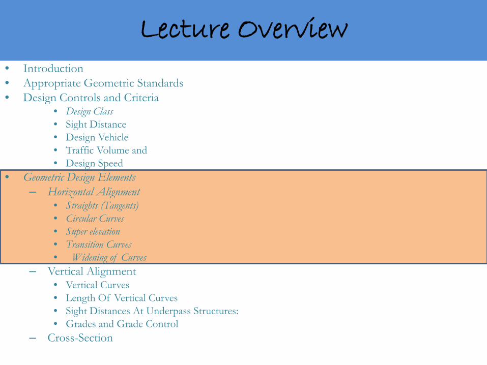
• Introduction • Appropriate Geometric Standards • Design Controls and Criteria
• Design Class • Sight Distance • Design Vehicle • Traffic Volume and • Design Speed
• Geometric Design Elements – Horizontal Alignment
• Straights (Tangents) • Circular Curves • Super elevation • Transition Curves • Widening of Curves
– Vertical Alignment • Vertical Curves • Length Of Vertical Curves • Sight Distances At Underpass Structures: • Grades and Grade Control
– Cross-Section
Lecture Overview
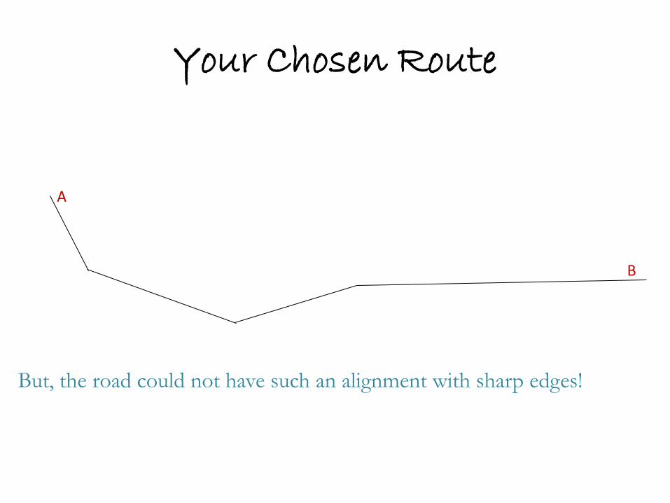
Your Chosen Route
But, the road could not have such an alignment with sharp edges!
A
B
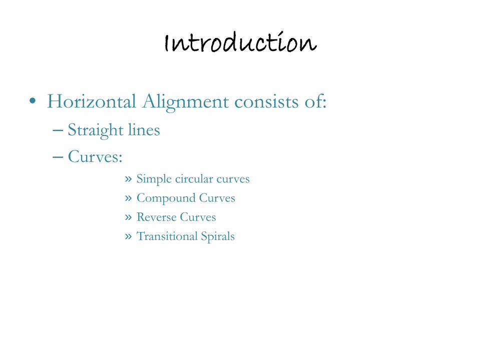
Introduction
• Horizontal Alignment consists of: – Straight lines – Curves:
» Simple circular curves » Compound Curves » Reverse Curves » Transitional Spirals
Considerations
A proper relation should be established between the design speed and curvature and their joint relations with super elevation and side friction. drainage

Simple Circular Curves - Terms
∆=deflection angle L=Length of Curve C=Chord Length R=Radius of Curvature M=Middle Ordinate E=External Distance T=Length of Tangent P.I.=Point of Intersection TC=Tangent to Circle CT=Circle to Tangent
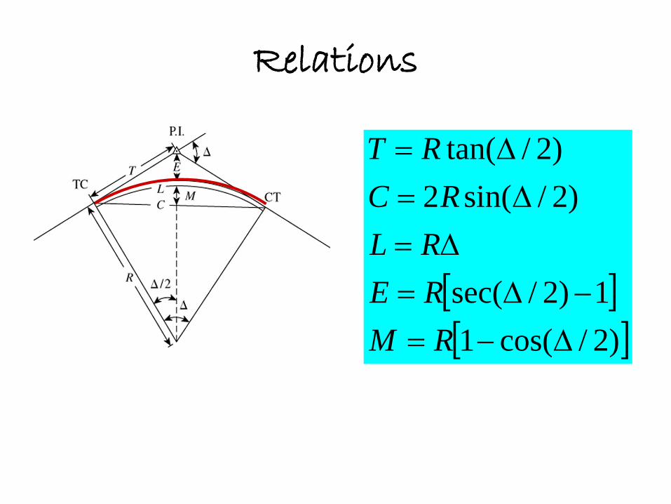
Relations
[ ][ ])2/cos(1
1)2/sec(
)2/sin(2)2/tan(
∆−=−∆=
∆=∆=
∆=
RMRERL
RCRT
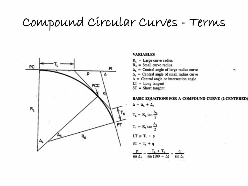
Compound Circular Curves - Terms
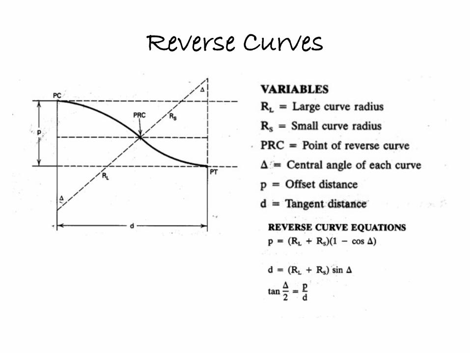
Reverse Curves

Stability of a VEH
a=radial acceleration; m=mass of vehicle; V=speed of vehicle; R=Radius of curvature; F=Frictional Resistance; R’=Reaction
When road has no camber and the VEH is on the verge of overturning
coefficient of friction
a
v
RFRmVF
mgR
′==
=′
//2
µRmV /2
mgF
R’
h
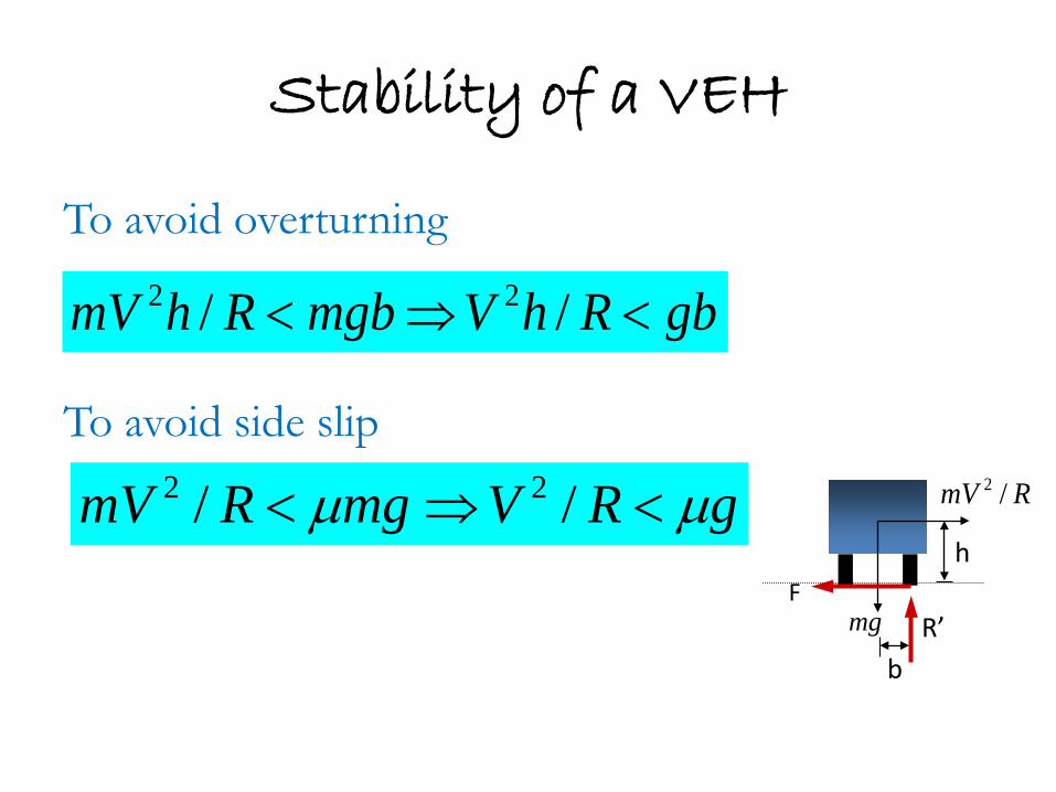
Stability of a VEH
To avoid overturning To avoid side slip
RmV /2
mgF
R’
h
gbRhVmgbRhmV <⇒< // 22
b
gRVmgRmV µµ <⇒< // 22
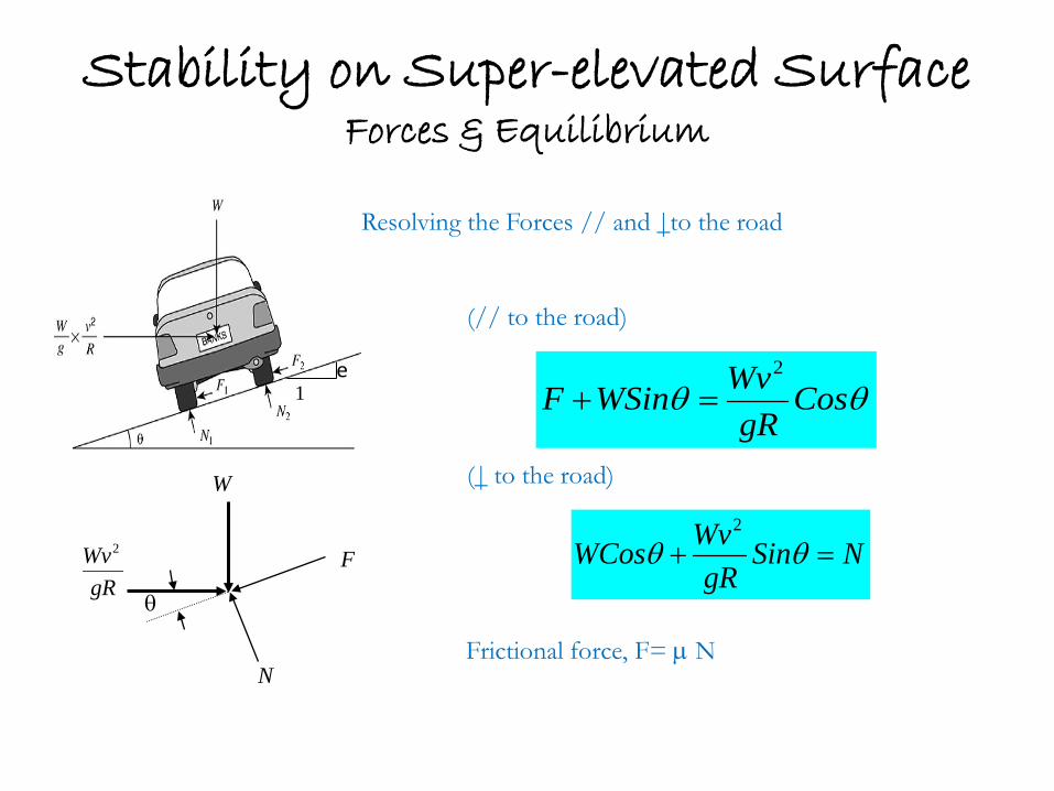
Resolving the Forces // and |to the road (// to the road) (| to the road)
Stability on Super-elevated Surface Forces & Equilibrium
θθ CosgR
WvWSinF2
=+
gRWv2
N
F
W
θ
Frictional force, F= µ N
NSingR
WvWCos =+ θθ2
e 1
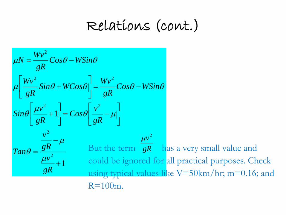
Relations (cont.)
1
1
2
2
22
22
2
+
−=
−=
+
−=
+
−=
gRv
gRv
Tan
gRvCos
gRvSin
WSinCosgR
WvWCosSingR
Wv
WSinCosgR
WvN
µ
µθ
µθµθ
θθθθµ
θθµ
gRv2µ
But the term has a very small value and could be ignored for all practical purposes. Check using typical values like V=50km/hr; m=0.16; and R=100m.
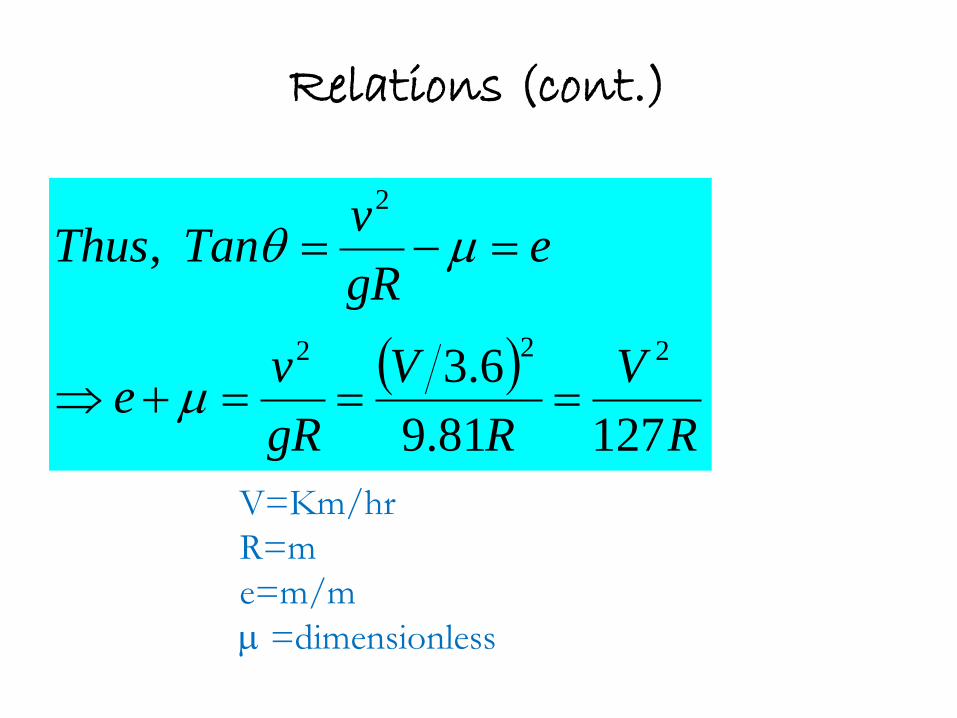
Relations (cont.)
( )R
VR
VgRve
egRvTanThus
12781.96.3
,
222
2
===+⇒
=−=
µ
µθ
V=Km/hr R=m e=m/m µ =dimensionless
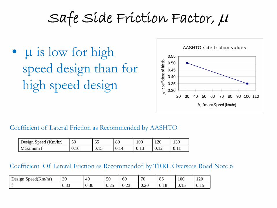
Safe Side Friction Factor, µ
• µ is low for high speed design than for high speed design
AASHTO side friction values
0.300.35
0.400.45
0.500.55
20 30 40 50 60 70 80 90 100 110
V, Design Speed (km/hr)
µ, c
oeffi
cient
of f
rictio
n
Design Speed (Km/hr) 50 65 80 100 120 130 Maximum f 0.16 0.15 0.14 0.13 0.12 0.11
Design Speed(Km/hr) 30 40 50 60 70 85 100 120 f 0.33 0.30 0.25 0.23 0.20 0.18 0.15 0.15
Coefficient of Lateral Friction as Recommended by AASHTO
Coefficient Of Lateral Friction as Recommended by TRRL Overseas Road Note 6
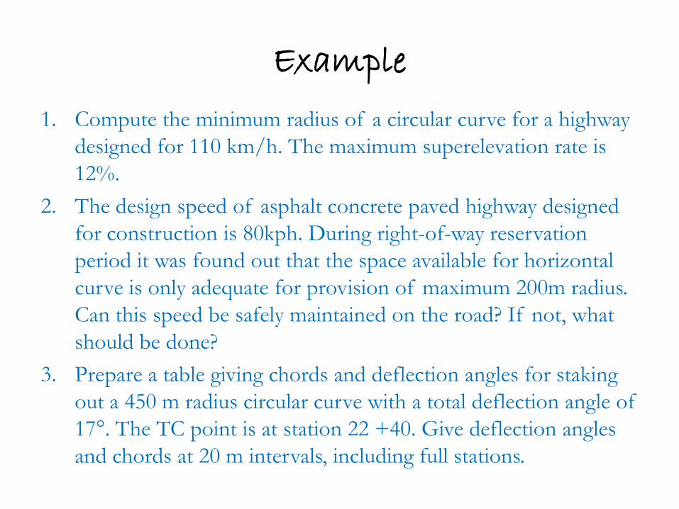
Example
1. Compute the minimum radius of a circular curve for a highway designed for 110 km/h. The maximum superelevation rate is 12%.
2. The design speed of asphalt concrete paved highway designed for construction is 80kph. During right-of-way reservation period it was found out that the space available for horizontal curve is only adequate for provision of maximum 200m radius. Can this speed be safely maintained on the road? If not, what should be done?
3. Prepare a table giving chords and deflection angles for staking out a 450 m radius circular curve with a total deflection angle of 17°. The TC point is at station 22 +40. Give deflection angles and chords at 20 m intervals, including full stations.
Super-elevation rate, e
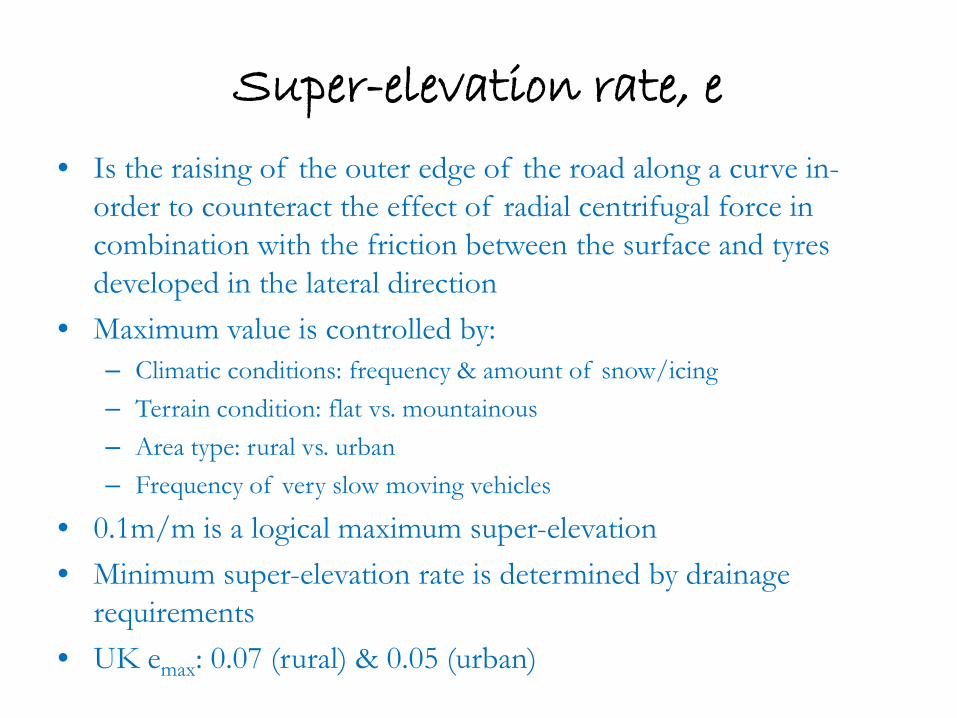
• Is the raising of the outer edge of the road along a curve in-order to counteract the effect of radial centrifugal force in combination with the friction between the surface and tyres developed in the lateral direction
• Maximum value is controlled by: – Climatic conditions: frequency & amount of snow/icing – Terrain condition: flat vs. mountainous – Area type: rural vs. urban – Frequency of very slow moving vehicles
• 0.1m/m is a logical maximum super-elevation • Minimum super-elevation rate is determined by drainage
requirements • UK emax: 0.07 (rural) & 0.05 (urban)
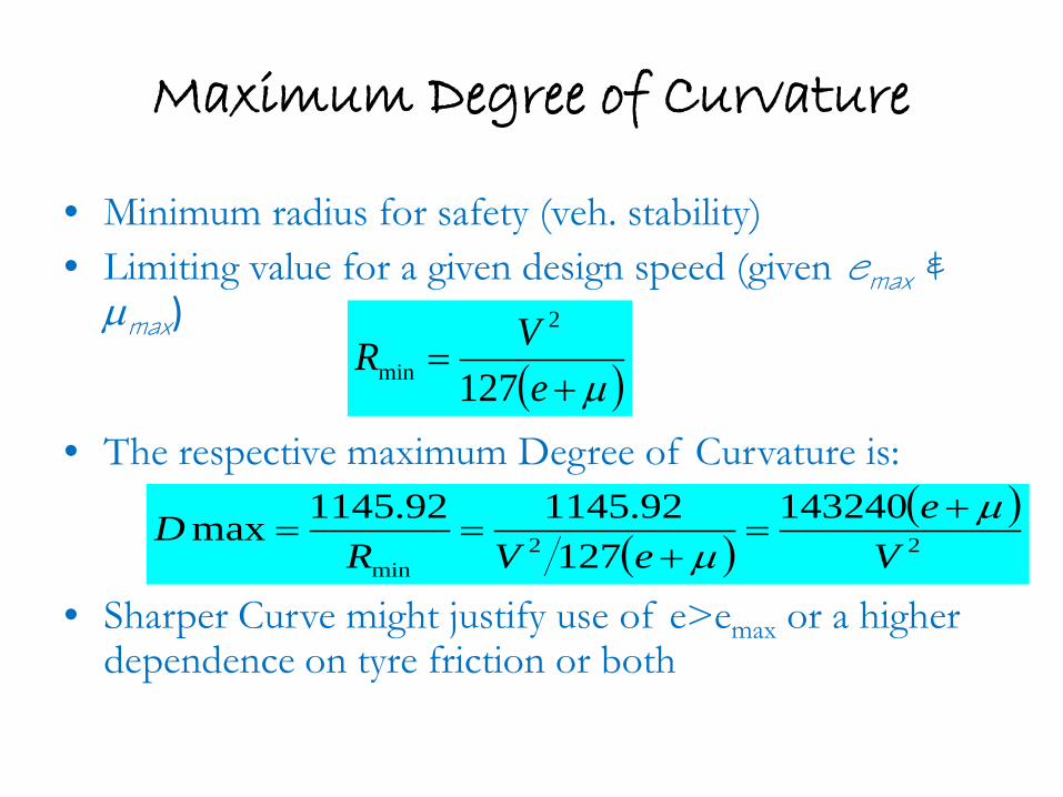
Maximum Degree of Curvature
• Minimum radius for safety (veh. stability) • Limiting value for a given design speed (given emax &
µmax)
• The respective maximum Degree of Curvature is:
• Sharper Curve might justify use of e>emax or a higher dependence on tyre friction or both
( )µ+=
eVR
127
2
min
( )( )22
min
143240127
92.114592.1145maxV
eeVR
D µµ
+=
+==
Application of Super-elevation
Is done in two stages: 1. Neutralizing the camber of the road gradually,
bringing it in to a straight line slope 2. Increasing the slope gradually until design super-
elevation is attained
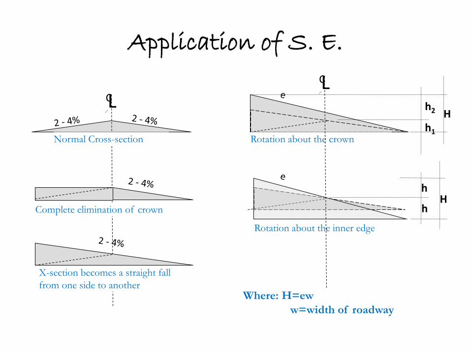
Application of S. E.
C L
Normal Cross-section
Complete elimination of crown
X-section becomes a straight fall from one side to another
Rotation about the crown
Rotation about the inner edge
C L
h H
h2
h1
h
Where: H=ew w=width of roadway
H
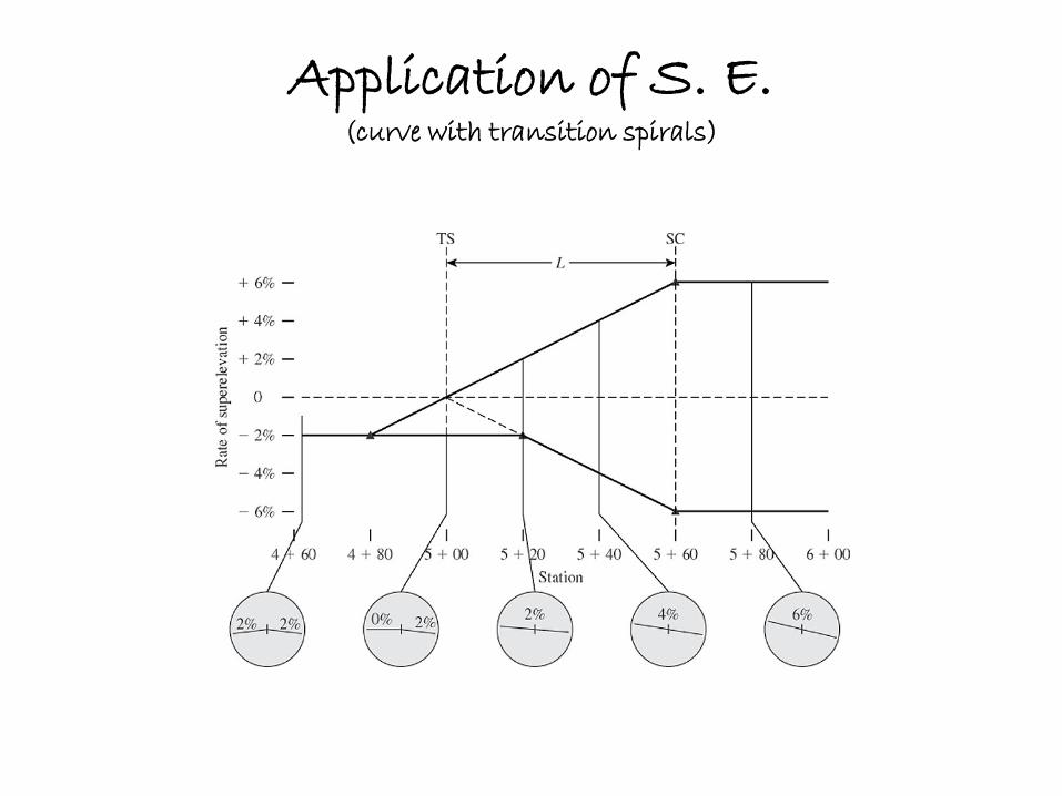
Application of S. E. (curve with transition spirals)
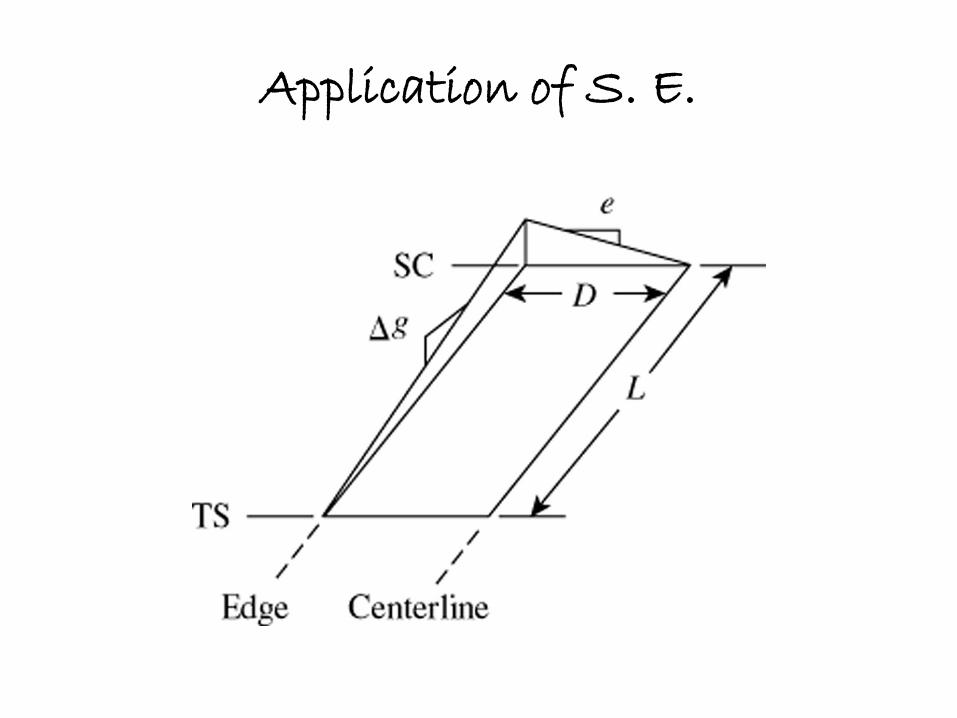
Application of S. E.
Application of Super-Elevation (for curves with no spirals)
• Super-elevation is started 1/2 to 1/3 into the tangent with the balance being applied with in the curve
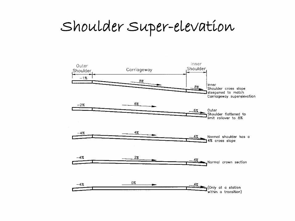
Shoulder Super-elevation
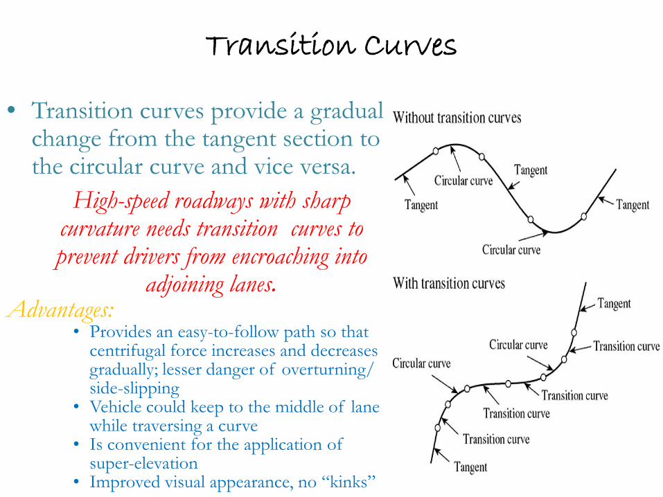
Transition Curves
• Transition curves provide a gradual change from the tangent section to the circular curve and vice versa.
High-speed roadways with sharp curvature needs transition curves to prevent drivers from encroaching into
adjoining lanes. Advantages:
• Provides an easy-to-follow path so that centrifugal force increases and decreases gradually; lesser danger of overturning/ side-slipping
• Vehicle could keep to the middle of lane while traversing a curve
• Is convenient for the application of super-elevation
• Improved visual appearance, no “kinks”
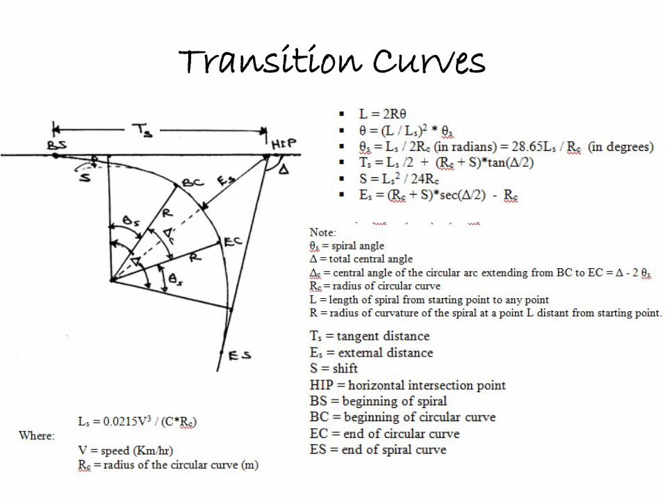
Transition Curves
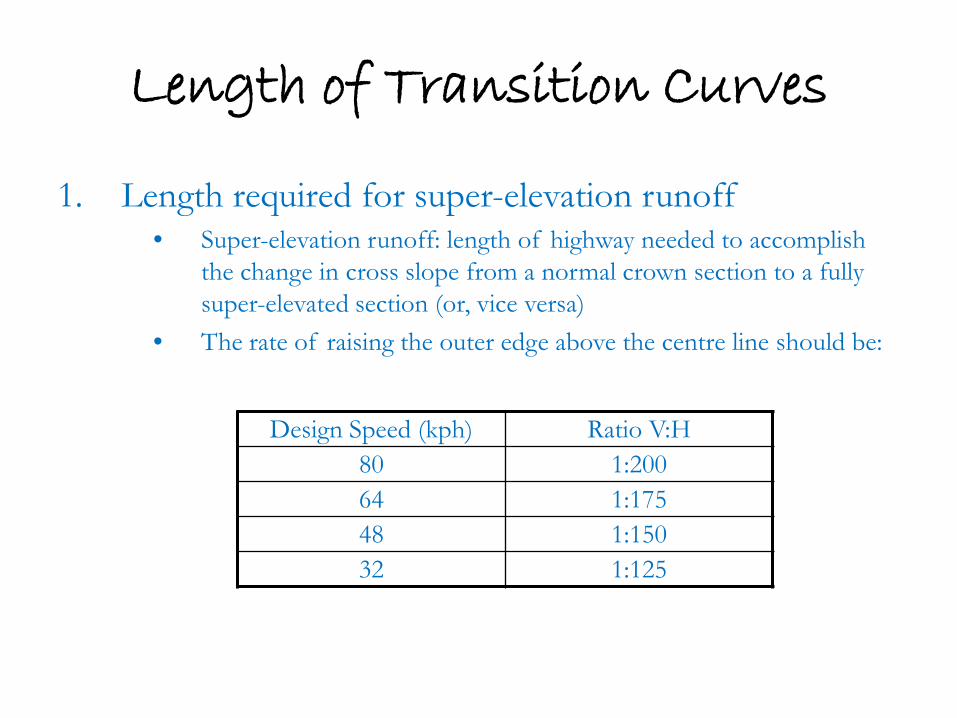
Length of Transition Curves
1. Length required for super-elevation runoff • Super-elevation runoff: length of highway needed to accomplish
the change in cross slope from a normal crown section to a fully super-elevated section (or, vice versa)
• The rate of raising the outer edge above the centre line should be:
Design Speed (kph) Ratio V:H 80 1:200 64 1:175 48 1:150 32 1:125
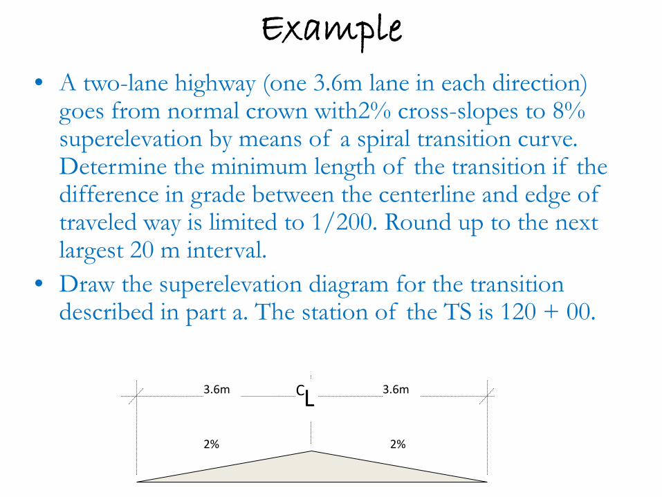
Example • A two-lane highway (one 3.6m lane in each direction)
goes from normal crown with2% cross-slopes to 8% superelevation by means of a spiral transition curve. Determine the minimum length of the transition if the difference in grade between the centerline and edge of traveled way is limited to 1/200. Round up to the next largest 20 m interval.
• Draw the superelevation diagram for the transition described in part a. The station of the TS is 120 + 00.
2% 2%
3.6m 3.6m C L
Length required for super-elevation runoff
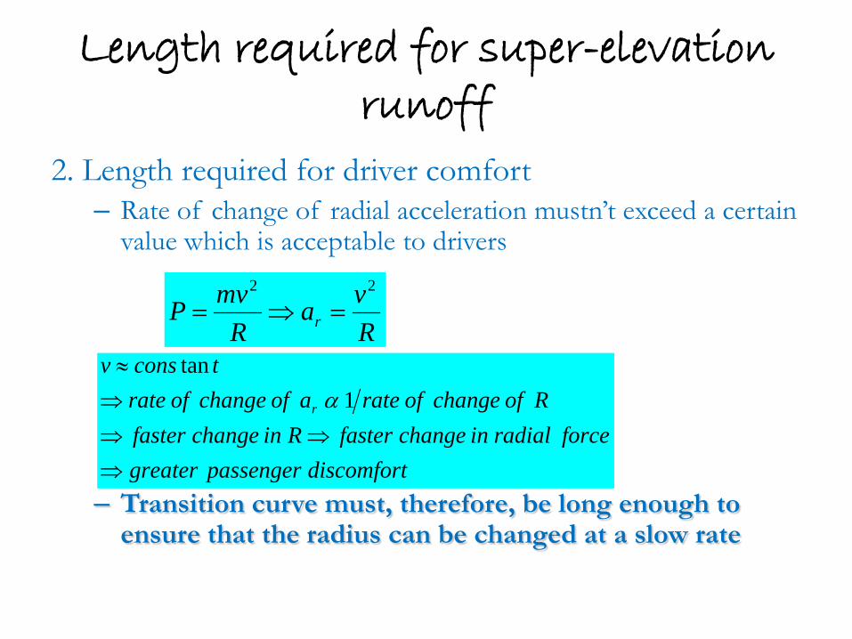
2. Length required for driver comfort – Rate of change of radial acceleration mustn’t exceed a certain
value which is acceptable to drivers
– Transition curve must, therefore, be long enough to ensure that the radius can be changed at a slow rate
Rva
RmvP r
22
=⇒=
discomfortpassengergreaterforceradialinchangefasterRinchangefaster
Rofchangeofrateaofchangeofratetconsv
r
⇒⇒⇒
⇒≈
1tan
α
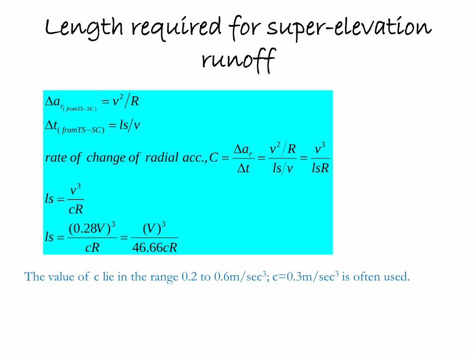
Length required for super-elevation runoff
cRV
cRVls
cRvls
lsRv
vlsRv
taCaccradialofchangeofrate
vlst
Rva
r
SCfromTS
r SCfromTS
66.46)()28.0(
.,
33
3
32
)(
2)(
==
=
==∆
∆=
=∆
=∆
−
−
The value of c lie in the range 0.2 to 0.6m/sec3; c=0.3m/sec3 is often used.
Widening of Highway Curves
Need – Rear wheels don’t follow front wheels, – Trailers fitted on trucks, don’t follow path of trucks
wheels – To have adequate sight-distances – Drivers tend to keep greater clearances with vehicles
coming from the opposite direction and might thus move out of a lane when traversing a curve
R2
R1 B f
L
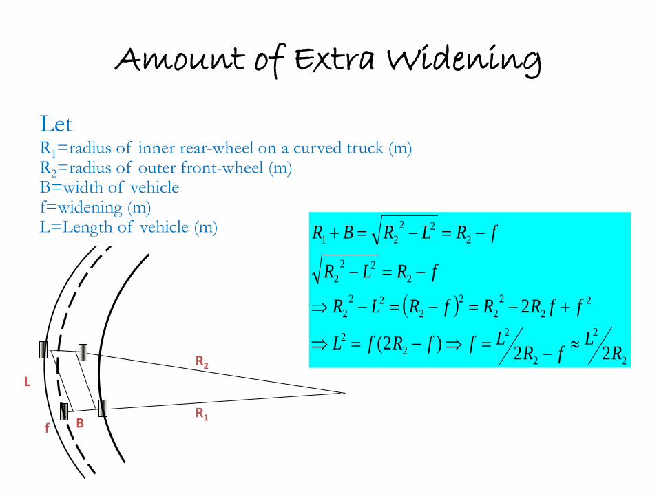
Amount of Extra Widening
Let R1=radius of inner rear-wheel on a curved truck (m) R2=radius of outer front-wheel (m) B=width of vehicle f=widening (m) L=Length of vehicle (m)
( )
2
2
2
22
2
22
22
22
222
222
2
222
21
22)2(
2
RL
fRLffRfL
ffRRfRLR
fRLR
fRLRBR
≈−=⇒−=⇒
+−=−=−⇒
−=−
−=−=+

Empirical formulas for Amount of Widening
• Vorshell
• Barnett
• Hickerson
DDw 462.007.0 +=
( )R
VLRRnw +−−= 22
Dw 1.01+=
Widening - Methods
• On a simple curve (i.e. with no spirals) widening should be applied on the inside edge of a pavement only. For curves with spirals, widening could be applied on the inside (only) or could be equally divided b/n the inside and outside
• Widening should be attained gradually over the s.e. runoff length but shorter lengths are sometimes used (usually this length is 30 – 60m).
• Widening is costly and very little is gained from a small amount of widening.

Sight Distance on Horizontal Curves
Considering a vehicle at A and an object at O, sight distance should at-least equal to safe stopping distance.
If the angle subtended at the centre of the circle is 2q, then
Centre line of Road
M
Sight distance a measured along centreline of inside lane
Sight line A O
))65.28(1(
)23.57(
,23.571802
RCosRm
RSCosCosR
mRRS
RSD
−=
==−=
=
θ
θθπ

Thank You!