Embed Size (px)
Citation preview
BUREAU OF LOCAL ROADS AND STREETS MANUAL
Chapter Forty-six
PAVEMENT REHABILITATION

BUREAU OF LOCAL ROADS & STREETS Apr 2012 PAVEMENT REHABILITATION 46(i)
Chapter Forty-Six PAVEMENT REHABILITATION
Table of Contents
Section Page 46-1 GENERAL ............................................................................................................ 46-1(1)
46-1.01 Pavement Rehabilitation Definitions ................................................... 46-1(1) 46-1.02 Minimum HMA Lift Thickness ............................................................. 46-1(1) 46-1.03 Skid Resistance on HMA Surface Courses ........................................ 46-1(1) 46-1.04 Density Testing on HMA Pavements .................................................. 46-1(1) 46-1.05 Selection of Rehabilitation Technique ................................................ 46-1(1) 46-1.06 Accessibility Requirement .................................................................. 46-1(2)
46-2 HMA OVERLAYS ................................................................................................. 46-2(1)
46-2.01 Introduction ......................................................................................... 46-2(1) 46-2.02 Evaluation of Structures Being Resurfaced ........................................ 46-2(1) 46-2.03 Reflective Crack Control ..................................................................... 46-2(1)
46-2.03(a) Materials ........................................................................ 46-2(1) 46-2.03(b) Applications .................................................................... 46-2(2)
46-2.04 Maintenance with Hot Mix Asphalt (HMA) or Warm Mix Asphalt
(WMA) ................................................................................................ 46-2(2) 46-2.05 Local Agency Functional Overlay (LAFO) Policy ................................ 46-2(2) 46-2.06 Local Agency Structural Overlay (LASO) Policy ................................. 46-2(2)
46-3 LOCAL AGENCY FUNCTIONAL OVERLAY (LAFO) POLICY ............................ 46-3(1)
46-3.01 Eligibility .............................................................................................. 46-3(1)
46-3.01(a) Length ............................................................................ 46-3(1) 46-3.01(b) Existing Design Criteria with Construction History ......... 46-3(1) 46-3.01(c) Existing Design Criteria without Construction
History ............................................................................ 46-3(1) 46-3.01(d) Geometric Upgrades ...................................................... 46-3(1) 46-3.01(e) Pavement Widening ....................................................... 46-3(1) 46-3.01(f) Crash History ................................................................. 46-3(2)
46-3.02 Application .......................................................................................... 46-3(2)
46-3.02(a) Construction Limits ........................................................ 46-3(2) 46-3.02(b) Pavement Repairs ......................................................... 46-3(2) 46-3.02(c) Lane Widths ................................................................... 46-3(2) 46-3.02(d) Crown and Cross Slope Adjustment .............................. 46-3(2) 46-3.02(e) Overlay Thickness ......................................................... 46-3(2)
BUREAU OF LOCAL ROADS & STREETS 46(ii) PAVEMENT REHABILITATION Apr 2012
46-3.02(f) Rollover Factor ............................................................... 46-3(3) 46-3.02(g) Structures ....................................................................... 46-3(3) 46-3.02(h) Drainage ........................................................................ 46-3(3) 46-3.02(i) Clear Zones ................................................................... 46-3(4) 46-3.02(j) Documentation ............................................................... 46-3(4)
46-4 LOCAL AGENCY STRUCTURAL OVERLAY (LASO) POLICY ........................... 46-4(1)
46-4.01 Structural Pavement Design Procedures ........................................... 46-4(1)
46-4.01(a) AASHTO Guide for Design of Pavement Structure (1993) ............................................................................. 46-4(1)
46-4.01(b) Modified AASHTO .......................................................... 46-4(1) 46-4.01(c) Asphalt Institute’s “Asphalt Overlays for Highway
and Street Rehabilitation” (MS-17) Deflection Analysis .......................................................................... 46-4(1)
46-4.02 Modified AASHTO Design for Overlays on Existing Flexible
Pavement/Bases ................................................................................ 46-4(2)
46-4.02(a) Application of Design Method ........................................ 46-4(2) 46-4.02(b) Classes of Roads and Streets ....................................... 46-4(2) 46-4.02(c) Design Period ................................................................ 46-4(2) 46-4.02(d) Structural Design Traffic ................................................ 46-4(3) 46-4.02(e) Traffic Factors ................................................................ 46-4(3) 46-4.02(f) Subgrade ....................................................................... 46-4(3) 46-4.02(g) Required Structural Number .......................................... 46-4(5) 46-4.02(h) Existing Structural Number ............................................ 46-4(5) 46-4.02(i) Overlay Thickness Design ............................................. 46-4(5) 46-4.02(j) Minimum Thickness and Material Requirements ........... 46-4(5)
46-4.03 Modified AASHTO Design for Overlays on Existing
Rigid/Composite Pavements .............................................................. 46-4(9)
46-4.03(a) Application of Design Method ........................................ 46-4(9) 46-4.03(b) Classes of Roads and Streets ..................................... 46-4(10) 46-4.03(c) Design Period .............................................................. 46-4(10) 46-4.03(d) Traffic Factors .............................................................. 46-4(10) 46-4.03(e) Required Composite Pavement Structural Number ..... 46-4(11) 46-4.03(f) Thickness Design Equations ........................................ 46-4(14) 46-4.03(g) Minimum Thickness and Material Requirements ......... 46-4(14)
46-4.04 Design Example ............................................................................... 46-4(15)
46-5 PCC INLAY/OVERLAY ON EXISTING ON HMA SURFACES ............................ 46-5(1)
46-5.01 Introduction ......................................................................................... 46-5(1)
46-5.01(a) Applicability .................................................................... 46-5(1)
BUREAU OF LOCAL ROADS & STREETS Apr 2012 PAVEMENT REHABILITATION 46(iii)
46-5.01(b) Limitations ...................................................................... 46-5(2)
46-5.02 Review of Existing Pavement Structure ............................................. 46-5(2)
46-5.02(a) Preliminary Pavement Investigation ............................... 46-5(2) 46-5.02(b) Detailed Pavement Investigation ................................... 46-5(2) 46-5.02(c) Existing and Projected Average Daily Traffic ................. 46-5(3) 46-5.02(d) Existing Pavement Structure Report .............................. 46-5(3)
46-5.03 Thickness Design Procedure .............................................................. 46-5(3)
46-5.03(a) Classes of Roads and Streets ....................................... 46-5(3) 46-5.03(b) Design Period ................................................................ 46-5(3) 46-5.03(c) Structural Design Traffic ................................................ 46-5(4) 46-5.03(d) Traffic Factor .................................................................. 46-5(4) 46-5.03(e) Joint Spacing ................................................................. 46-5(4) 46-5.03(f) Thickness Design ........................................................... 46-5(5)
46-5.04 Other Design Considerations ........................................................... 46-5(10)
46-5.04(a) Drainage Considerations ............................................. 46-5(10) 46-5.04(b) Pavement Preparation and Profile ............................... 46-5(10) 46-5.04(c) Final Finish ................................................................... 46-5(10) 46-5.04(d) Traffic Control .............................................................. 46-5(11) 46-5.04(e) Construction Staging .................................................... 46-5(11)
46-5.05 Example Calculations ....................................................................... 46-5(12)
46-6 FLEXIBLE PAVEMENT IN-PLACE RECYCLING ................................................ 46-6(1)
46-6.01 Introduction ......................................................................................... 46-6(1) 46-6.02 Hot In-Place Recycling (HIR) .............................................................. 46-6(2)
46-6.02(a) HIR - Surface Recycling ................................................. 46-6(2) 46-6.02(b) HIR - Remixing ............................................................... 46-6(2) 46-6.02(c) HIR - Repaving .............................................................. 46-6(2)
46-6.03 Cold In-Place Recycling (CIR) ............................................................ 46-6(3)
46-6.03(a) General .......................................................................... 46-6(3)
46-6.04 Full Depth Reclamation (FDR) ........................................................... 46-6(3)
46-6.04(a) General .......................................................................... 46-6(3)
46-6.05 CIR and FDR Design Procedures ...................................................... 46-6(4)
46-6.05(a) Initial Investigation ......................................................... 46-6(5) 46-6.05(b) Preliminary Material Classification ................................. 46-6(6)

BUREAU OF LOCAL ROADS & STREETS 46(iv) PAVEMENT REHABILITATION Apr 2012
46-6.05(c) Pavement Design ........................................................... 46-6(9) 46-6.05(d) Determination of Project Criteria .................................. 46-6(10) 46-6.05(e) Mix Design ................................................................... 46-6(10)
46-7 RUBBLIZATION ................................................................................................... 46-7(1) 46-8 RESOURCES ...................................................................................................... 46-8(1)
BUREAU OF LOCAL ROADS & STREETS Jan 2012 PAVEMENT REHABILITATION 46-1(1)
Chapter Forty-six PAVEMENT REHABILITATION
46-1 GENERAL
46-1.01 Pavement Rehabilitation Definitions
See Section 44-1.01 of this manual 46-1.02 Minimum HMA Lift Thickness
All Hot Mix Asphalt (HMA) surface, binder, and leveling binder lifts must comply with the lift thicknesses in Figure 44-1A. 46-1.03 Skid Resistance on HMA Surface Courses
See Section 44-1.03 of this manual. 46-1.04 Density Testing on HMA Pavements
See Section 44-1.04 of this manual. 46-1.05 Selection of Rehabilitation Technique
The most important part of rehabilitation process is the proper selection of technique or techniques process to be used. Designers should consider the following criteria when selecting the appropriate rehabilitation technique:
• Pavement Condition
• Construction and Maintenance Records
• Structural Capacity
• Existing Materials In-Place
• Identify Cause of Distresses
• Highway Geometrics
• Economic Analysis
Factors such as design traffic, pavement cross section, in situ materials and climate should be investigated using historic information and pavement assessments. A detailed review of construction/maintenance history and pavement management system will assist in determining:
• Age, type, and thickness of various layers
• Quality of construction material
BUREAU OF LOCAL ROADS & STREETS 46-1(2) PAVEMENT REHABILITATION Jan 2012 • Subgrade Stability
• Pavement condition and remaining service life
• Type, severity, and frequency of pavement distresses
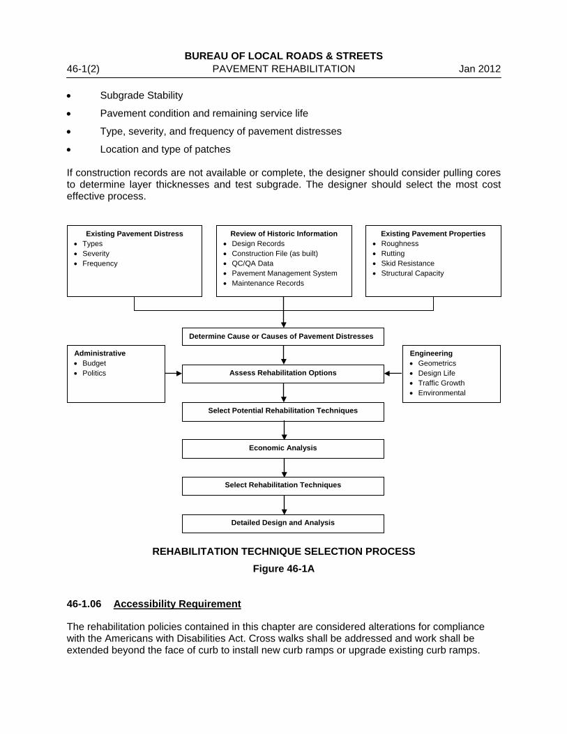
• Location and type of patches If construction records are not available or complete, the designer should consider pulling cores to determine layer thicknesses and test subgrade. The designer should select the most cost effective process.
REHABILITATION TECHNIQUE SELECTION PROCESS Figure 46-1A
46-1.06 Accessibility Requirement
The rehabilitation policies contained in this chapter are considered alterations for compliance with the Americans with Disabilities Act. Cross walks shall be addressed and work shall be extended beyond the face of curb to install new curb ramps or upgrade existing curb ramps.
Existing Pavement Distress • Types • Severity • Frequency
Review of Historic Information • Design Records • Construction File (as built) • QC/QA Data • Pavement Management System • Maintenance Records
Existing Pavement Properties • Roughness • Rutting • Skid Resistance • Structural Capacity
Determine Cause or Causes of Pavement Distresses
Assess Rehabilitation Options
Engineering • Geometrics • Design Life • Traffic Growth • Environmental
Administrative • Budget • Politics
Select Potential Rehabilitation Techniques
Economic Analysis
Select Rehabilitation Techniques
Detailed Design and Analysis
BUREAU OF LOCAL ROADS & STREETS Apr 2012 PAVEMENT REHABILITATION 46-2(1) 46-2 HMA OVERLAYS
46-2.01 Introduction
HMA overlays are used to correct functional and structural deficiencies. Existing pavement conditions and estimates of future traffic dictate the thicknesses of these overlays. Functional deficiency arises from any conditions that adversely affect the highway user. These include poor surface friction and texture, hydroplaning and splash from wheel path rutting, and excessive weathering, raveling, and block cracking. Structural deficiency arises from any conditions that adversely affect the load-carrying capability of the pavement structure. These include inadequate thickness, loss of base or subgrade support, and moisture damage. It should be noted that several types of distress (e.g., distresses caused by poor construction techniques, low temperature cracking, base failure) are not initially caused by traffic loads but do become more severe under traffic to the point that they also detract from the load-carrying capability of the pavement. It is important that the designer consider the type of deterioration present when determining whether the pavement has functional or structural deficiencies. For pavements with adequate existing structure, the overlay thickness is the thickness needed to correct the functional problem. Pavements that are structurally deficient require an overlay designed to upgrade the structural capacity. 46-2.02 Evaluation of Structures Being Resurfaced
All structures greater than 20.0 feet (6.1 m) in length within the limits of a resurfacing project that are not gapped should be evaluated for structural adequacy with the proposed resurfacing. This includes structures with zero increase in surfacing depth, such as those involving removal of surfacing with replacement with of equal thickness. These structures should be evaluated for structural adequacy and submitted to the Bureau of Bridges and Structures (BBS) for approval during the preliminary design phase. All structure condition ratings of these structures must be a “5” or greater. For such structures that are not being gapped, a Form BLR 10220 “Asbestos Determination Certification” will be required. The BBS will evaluate the adequacy of the structure, and record the status of the asbestos Form BLR 10220, before approval. 46-2.03 Reflective Crack Control
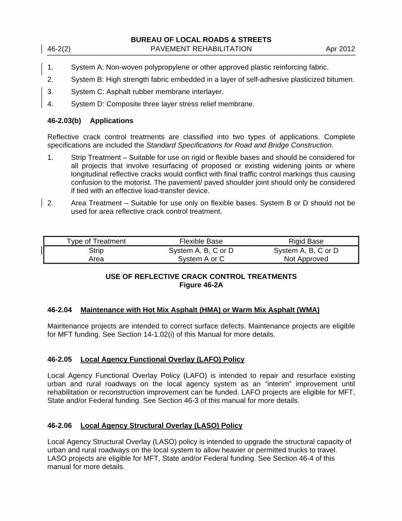
On pavements where existing cracks may propagate as reflective cracks, a reflective crack control treatment should be performed prior to the application of the HMA overlay. Such treatment should incorporate approved materials and follow recommended construction practices. Figure 46-2A summarizes the use of reflective crack control treatments. 46-2.03(a) Materials
The following materials have been developed for the control of reflective cracking in HMA overlays. Complete specifications are included in the Standard Specifications for Road and Bridge Construction.
BUREAU OF LOCAL ROADS & STREETS 46-2(2) PAVEMENT REHABILITATION Apr 2012 1. System A: Non-woven polypropylene or other approved plastic reinforcing fabric.
2. System B: High strength fabric embedded in a layer of self-adhesive plasticized bitumen.
3. System C: Asphalt rubber membrane interlayer.
4. System D: Composite three layer stress relief membrane.
46-2.03(b) Applications
Reflective crack control treatments are classified into two types of applications. Complete specifications are included the Standard Specifications for Road and Bridge Construction.
1. Strip Treatment – Suitable for use on rigid or flexible bases and should be considered for all projects that involve resurfacing of proposed or existing widening joints or where longitudinal reflective cracks would conflict with final traffic control markings thus causing confusion to the motorist. The pavement/ paved shoulder joint should only be considered if tied with an effective load-transfer device.
2. Area Treatment – Suitable for use only on flexible bases. System B or D should not be used for area reflective crack control treatment.
Type of Treatment Flexible Base Rigid Base Strip System A, B, C or D System A, B, C or D Area System A or C Not Approved
USE OF REFLECTIVE CRACK CONTROL TREATMENTS
Figure 46-2A 46-2.04 Maintenance with Hot Mix Asphalt (HMA) or Warm Mix Asphalt (WMA)
Maintenance projects are intended to correct surface defects. Maintenance projects are eligible for MFT funding. See Section 14-1.02(i) of this Manual for more details. 46-2.05 Local Agency Functional Overlay (LAFO) Policy
Local Agency Functional Overlay Policy (LAFO) is intended to repair and resurface existing urban and rural roadways on the local agency system as an “interim” improvement until rehabilitation or reconstruction improvement can be funded. LAFO projects are eligible for MFT, State and/or Federal funding. See Section 46-3 of this manual for more details. 46-2.06 Local Agency Structural Overlay (LASO) Policy
Local Agency Structural Overlay (LASO) policy is intended to upgrade the structural capacity of urban and rural roadways on the local system to allow heavier or permitted trucks to travel. LASO projects are eligible for MFT, State and/or Federal funding. See Section 46-4 of this manual for more details.

BUREAU OF LOCAL ROADS & STREETS Jan 2012 PAVEMENT REHABILITATION 46-3(1) 46-3 LOCAL AGENCY FUNCTIONAL OVERLAY (LAFO) POLICY
46-3.01 Eligibility
The following guidelines should be used when determining a project’s eligibility for the LAFO Policy. 46-3.01(a) Length
A project should be a part of a route that extends between logical termini. Rural segments of a project should be at least 1 mile (1.6 km) in length. Urban segments of a project should be at least one block in length with geometric continuity for contiguous blocks.
46-3.01(b) Existing Design Criteria with Construction History
All highways must have met IDOT’s design requirements at the time of initial construction. Ensure all design plans are on file and available to IDOT for review upon request. The districts will review projects to verify that all requirements are met. If the highway has been resurfaced since initial construction, verify the design meets the criteria for Section 46-3.01(c)3 and Section 46-3.01(c)4 below in existing design criteria without construction history. 46-3.01(c) Existing Design Criteria without Construction History
Highways and/or streets constructed under a local agency’s supervision, where the design plans and construction records are not available to IDOT, will require the following:
1. A typical cross section showing existing and proposed work.
2. A certification from the Local Public Agency’s (LPA) engineer that the existing pavement is structurally sound, has adequate pavement design thickness, and is maintained properly. It is recommended that pavement thickness and any widening thickness be verified by coring or other means, at maximum 750 ft (230 m) intervals, alternating left and right of the centerline.
3. A determination that the horizontal and vertical alignments do not deviate more than 15 mph (25 km/h) less than the design speed required under current policy for existing highways; however, the design speed shall not be less than 30 mph (50 km/h). Sag vertical curves generally may be retained
4. A statement from the LPA’s design engineer that adequate drainage exists and the proposed work will not negatively impact the pavement drainage capabilities.
46-3.01(d) Geometric Upgrades
Projects involving geometric revisions (other than minor superelevation corrections) will not be eligible under this program. 46-3.01(e) Pavement Widening
Pavement widening, and/or acquisition of right-of-way will not be allowed.
BUREAU OF LOCAL ROADS & STREETS 46-3(2) GEOMETRIC DESIGN OF EXISTING HIGHWAYS Jan 2012 46-3.01(f) Crash History
High crash locations will not be allowed to be improved under the LAFO policy unless a resurfacing or superelevation improvement can be considered an effective countermeasure to prevent future crashes. Highways on the state 5% Safety Report or other locations experiencing higher than expected fatal and serious injury crashes for the traffic volume, geometric characteristics, and/or posted speed limit should be improved according to Chapter 32 or Chapter 33 of the BLRS Manual. 46-3.02 Application
The following requirements will apply to LAFO projects. 46-3.02(a) Construction Limits
Construction limits for rural type cross sections are from the outside edge of the shoulder to the outside edge of shoulder. Protect the surface edges by building up the shoulders with material equal or superior to the existing shoulder material. Construction limits for urban type cross sections will be from face-of-curb to face-of-curb except for where curb ramp are required according to Section 46-1.06. 46-3.02(b) Pavement Repairs
The project shall not have extensive load-related distresses. A maximum of 10% of the pavement area will be allowed to be patched for rigid, composite, and full-depth pavements. A maximum of 20% of the pavement area will be allowed for base repair of conventional flexible pavements. 46-3.02(c) Lane Widths
Projects shall have minimum travel lane widths of 9 ft (2.7 m) for rural sections and 10 ft (3.0 m) for urban sections, centerline to edge of travel lane where there is no parking lane. The minimum parking lane width allowed is 8 ft (2.4 m) including gutter flag. 46-3.02(d) Crown and Cross Slope Adjustment
The use of milling, leveling course, heat scarifying, planing, cold in-place recycling, hot in-place recycling, or other methods of re-establishing the base cross slope and/or crown is highly recommended for LAFO projects. 46-3.02(e) Overlay Thickness
A HMA overlay up to 3.75 in (95 mm), including leveling binder to fill depressions and to correct crown deficiencies, may be placed upon the existing pavement surface. The milling of a HMA pavement to any depth and replacing this material with HMA up to the same thickness as milling operation plus 2 in (50 mm) may be performed under LAFO policy.
BUREAU OF LOCAL ROADS & STREETS Jan 2012 PAVEMENT REHABILITATION 46-3(3) For pavements with an existing Average Daily Traffic (ADT) of 400 or less, the use of cold-mix material or aggregate base course will be allowed to improve the existing base. The minimum cold-mix or aggregate base course thickness allowed will be 4 in (100 mm). An A-1 or A-2 surface treatment over the cold-mix material is required. An A-2 or A-3 surface treatment is required for the aggregate base material. 46-3.02(f) Rollover Factor
By thickening the pavement structure, the shoulder cross slopes for rural type cross sections will increase. Through horizontal curves, the maximum rollover factor (algebraic difference between traveled way and shoulder slopes) should not be greater than 10% where the shoulder width is 6 ft (1.8 m) or wider. Where the shoulder width is less than 6 ft (1.8 m), the maximum rollover factor will be 12%. 46-3.02(g) Structures
Structures with structural capacity less than H-15 (M-13.5) on highways functionally classified as local, or HS-15 (MS-13.5) on highways functionally classified as collectors or arterials may be gapped if they are included in the Multi-Year Improvement Program. Gapping is where the resurfacing is terminated prior to the bridge approach guardrail instead of adjacent to the bridge. For structures that have a structural capacity greater than H-15 (M-13.5) on highways functionally classified as local, or HS-15 (MS-13.5) on highways functionally classified as collectors or arterials resurfacing is optional. The existing rail or curb height, condition and adequacy of the bridge to accept the surfacing must be considered. Structurally sound bridge decks with poor riding quality or worn bituminous surfaces that would jeopardize the safety of the motorist or cause undue discomfort should be repaired and resurfaced. Resurfacing may be extended across decks with appropriate repairs (waterproofing recommended). If the bridge cannot safely carry the additional dead load resulting from resurfacing, gap the bridge. For structures greater than 20.0 feet (6.1 m) in length that are not being gapped, Form BLR 10220 “Asbestos Determination Certification” will be required. All structure condition ratings of these structures must be a “5” or greater. The Bureau of Bridges & Structures (BBS) will evaluate the structural adequacy of the structure, and record the status of the asbestos Form BLR 10220, before approval of the LAFO project. Projects with narrow bridges will not be allowed. A bridge width cannot be less than the pavement width of the typical section included in the LAFO project. The local agency has the option of addressing bridge curbs and retrofitting bridge rails.
46-3.02(h) Drainage
Only drainage corrections to restore the road cross section or to correct drainage problems within the eligible segments shall be allowed. This includes replacement/repair of crossroad culverts beneath the roadway and into the foreslopes, damaged curb and gutter, inlets, catch basins, and manholes. Minimal ditch work at the crossroad pipe culverts will be allowed to ensure adequate drainage. Efforts should be made on curb and gutter sections to retain the flow line of the gutter and adequate curb height.

BUREAU OF LOCAL ROADS & STREETS 46-3(4) GEOMETRIC DESIGN OF EXISTING HIGHWAYS Jan 2012 46-3.02(i) Clear Zones
Roadside hazards, such as bridge ends, guardrail, mail boxes, and others, located between the outer edge of shoulders shall be addressed. 46-3.02(j) Documentation
All LAFO projects are considered as Categorical Exclusion Group I. Form BLR 46300, a location map, and a typical section shall be submitted for all LAFO candidate projects regardless of funding. For LAFO projects that involve a structure, the Form BLR 46300 will be forwarded to the Local Bridge Unit for the approval of the Engineer of Bridges and Structures.

BUREAU OF LOCAL ROADS & STREETS Apr 2012 PAVEMENT REHABILITATION 46-4(1) 46-4 LOCAL AGENCY STRUCTURAL OVERLAY (LASO) POLICY
When it is proposed to place a HMA surface on an existing rigid or full depth HMA pavement, and upgrade the structure of the pavement, the thickness of the overlay may be determined by one of the following procedures. The District BLRS must approve any modifications or different design method. 46-4.01 Structural Pavement Design Procedures
46-4.01(a) AASHTO Guide for Design of Pavement Structure (1993)
Part III, Chapter 5 provides the designer with overlay thickness design procedures to address structural deficiencies in various types of existing pavements (flexible and rigid bases). 46-4.01(b) Modified AASHTO
This method may be used when designing an overlay on existing flexible pavements or flexible base (see Section 46-4.02) or on existing rigid or composite pavements (see Section 46-4.03) by estimating the structural number value of the existing material and determining the IBV of the subgrade. The designer may then select the surface thickness and any additional base thickness required to satisfy the design structural number. 46-4.01(c) Asphalt Institute’s “Asphalt Overlays for Highway and Street Rehabilitation”
(MS-17) Deflection Analysis
Deflection is the amount of downward vertical movement of a pavement surface due to the application of a load. The magnitude of the pavement deflection is an indicator of the pavement’s ability to withstand traffic loading. Research has established correlations between the wheel load, pavement deflections, and repetitions of the load. Bituminous overlays on existing flexible pavements/bases may be designed by deflection analysis in accordance with the following procedure:
1. Take an appropriate number of deflection readings on the existing roadway to be resurfaced. Obtain pavement deflections at a minimum rate of 20 per mile.
2. Convert the deflection readings to spring (critical period) deflections. Conversions may be based on historical data, the Asphalt Institute’s recommended procedure, or engineering judgment.
3. Tabulate the deflections and compute a standard deviation.
4. Deflections that fall outside the mean deflection plus 2 standard deviations should be set aside for special consideration. These areas will require additional treatment and/or additional structure.
5. Compute a traffic factor for the project.
6. Using the mean deflection plus 2 standard deviations, perform the Asphalt Institute’s deflection based HMA overlay design procedures.

BUREAU OF LOCAL ROADS & STREETS 46-4(2) GEOMETRIC DESIGN OF EXISTING HIGHWAYS Apr 2012 46-4.02 Modified AASHTO Design for Overlays on Existing Flexible Pavement/Bases
46-4.02(a) Application of Design Method
The modified AASHTO design procedures for flexible pavements enable the designer to determine the material types and thicknesses for the various layers of a flexible pavement that are required to carry a specified volume and composition of traffic for a designated period of time while retaining a serviceability level at or above a selected minimum value. Application of this design method involves the following steps: 1. Determine Traffic Factor. Use the following procedures to determine the traffic factor:
a. Determine the facility class (e.g., Class I, II, III, or IV) and the design period; see Sections 46-4.02(b) and 46-4.02(c).
b. Determine the actual structural design traffic as described in Section 46-4.02(d). c. Based on the facility class, select the appropriate traffic factor equation from
Figure 46-4B; see Section 46-4.02(e). d. Calculate the actual traffic factor for use in design.
2. Determine the Immediate Bearing Value. Determine the Immediate Bearing Value of the roadbed soil; see Section 46-4.02(f).
3. Determine the Required Structural Number (SNF). Determine the required flexible pavement structural number (SNF) using the appropriate design nomograph for the facility class (i.e., Figure 46-4D for Class I facilities or Figure 46-4E for Class II, III, and IV facilities); see Section 46-4.02(g).
4. Determine the Existing Structural Number (SNF,e). Determine the existing flexible pavement structural number (SNF,e) using the appropriate coefficients from Figure 46-4F, the thicknesses of the existing pavement structure, and Equation 46-4.1 in Section 46-4.02(h).
5. Determine Structural Overlay Thickness. Determine the overlay thickness using equation 46-4.2 in Section 46-4.02(i).
6. Compare with Minimum Criteria. Compare the selected design with the minimum requirements presented in Figure 46-4G to ensure that the minimum design requirements have been met; see Section 46-4.02(j).
46-4.02(b) Classes of Roads and Streets
The class of the road or street for which the bituminous overlay design is being determined is dependent upon the structural design traffic. These road classifications are defined in Section 44-1.01. 46-4.02(c) Design Period
The design period DP is the length of time in years that the bituminous overlay is being designed to serve the structural design traffic. For bituminous overlays, the minimum DP allowed is 15 years for Class I, II, III, and IV roads and streets. However, designers are encouraged to determine thicknesses for both 15 year and 20 year DP’s prior to selecting the final design thickness.
BUREAU OF LOCAL ROADS & STREETS Apr 2012 PAVEMENT REHABILITATION 46-4(3) 46-4.02(d) Structural Design Traffic
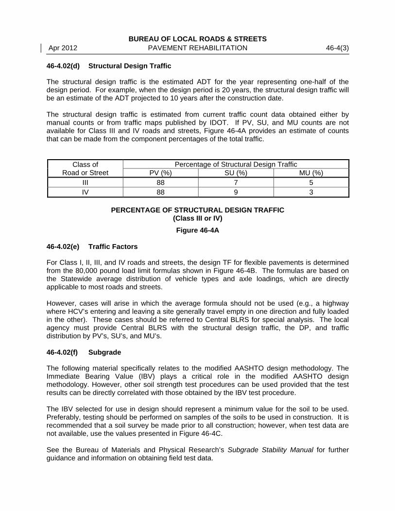
The structural design traffic is the estimated ADT for the year representing one-half of the design period. For example, when the design period is 20 years, the structural design traffic will be an estimate of the ADT projected to 10 years after the construction date. The structural design traffic is estimated from current traffic count data obtained either by manual counts or from traffic maps published by IDOT. If PV, SU, and MU counts are not available for Class III and IV roads and streets, Figure 46-4A provides an estimate of counts that can be made from the component percentages of the total traffic.
Class of Road or Street
Percentage of Structural Design Traffic PV (%) SU (%) MU (%)
III 88 7 5 IV 88 9 3
PERCENTAGE OF STRUCTURAL DESIGN TRAFFIC
(Class III or IV) Figure 46-4A
46-4.02(e) Traffic Factors
For Class I, II, III, and IV roads and streets, the design TF for flexible pavements is determined from the 80,000 pound load limit formulas shown in Figure 46-4B. The formulas are based on the Statewide average distribution of vehicle types and axle loadings, which are directly applicable to most roads and streets. However, cases will arise in which the average formula should not be used (e.g., a highway where HCV’s entering and leaving a site generally travel empty in one direction and fully loaded in the other). These cases should be referred to Central BLRS for special analysis. The local agency must provide Central BLRS with the structural design traffic, the DP, and traffic distribution by PV’s, SU’s, and MU’s. 46-4.02(f) Subgrade
The following material specifically relates to the modified AASHTO design methodology. The Immediate Bearing Value (IBV) plays a critical role in the modified AASHTO design methodology. However, other soil strength test procedures can be used provided that the test results can be directly correlated with those obtained by the IBV test procedure. The IBV selected for use in design should represent a minimum value for the soil to be used. Preferably, testing should be performed on samples of the soils to be used in construction. It is recommended that a soil survey be made prior to all construction; however, when test data are not available, use the values presented in Figure 46-4C. See the Bureau of Materials and Physical Research’s Subgrade Stability Manual for further guidance and information on obtaining field test data.

BUREAU OF LOCAL ROADS & STREETS 46-4(4) GEOMETRIC DESIGN OF EXISTING HIGHWAYS Apr 2012
Class I Roads and Streets
4 or 5 Lane Pavements (Rural and Urban) 0000001
MU139217SU62559PV0470DPTF,,
)...( ++=
6 or More Lane Pavements (Rural) 0000001
MU012193SU00053PV0290DPTF,,
)...( ++=
6 or More Lane Pavements (Urban) 0000001
MU536178SU02549PV0120DPTF,,
)...( ++=
One-way Streets and Pavements (Rural and Urban) 0000001
MU265241SU2566PV0730DPTF,,
)...( ++=
Class II Roads and Streets
2 or 3 Lane Pavements 0000001MU72192SU0356PV0730DPTF
,,)...( ++
=
Class III Roads and Streets
2 or 3 Lane Pavements 0000001MU175192SU5754PV0730DPTF
,,)...( ++
=
Class IV Roads and Streets
2 Lane Pavement 0000001MU4239SU934PV0730DPTF
,,)...( ++
=
HMA OVERLAY ON FLEXIBLE PAVEMENT TRAFFIC FACTOR EQUATIONS
(80,000 Pound Load Limit) Figure 46-4B
Soil Classification IBV A-1
A-2-4, A-2-5 A-2-6, A-2-7
A-3 A-4, A-5, A-6 A-7-5, A-7-6
20 15 12 10 3 2
SUGGESTED IBV VALUES FOR VARIOUS SOIL CLASSIFICATIONS
Figure 46-4C
BUREAU OF LOCAL ROADS & STREETS Apr 2012 PAVEMENT REHABILITATION 46-4(5) 46-4.02(g) Required Structural Number
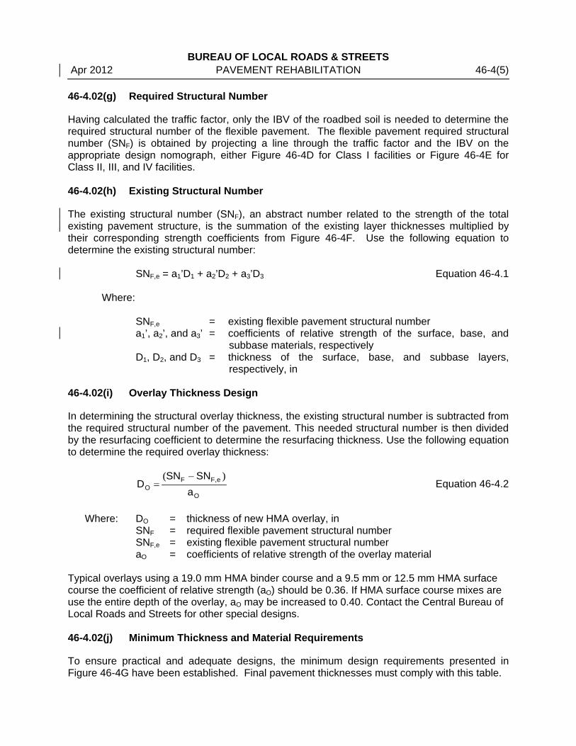
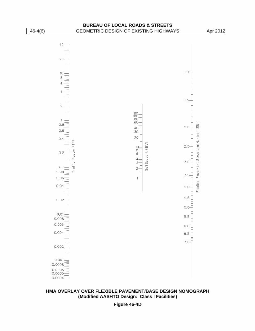
Having calculated the traffic factor, only the IBV of the roadbed soil is needed to determine the required structural number of the flexible pavement. The flexible pavement required structural number (SNF) is obtained by projecting a line through the traffic factor and the IBV on the appropriate design nomograph, either Figure 46-4D for Class I facilities or Figure 46-4E for Class II, III, and IV facilities. 46-4.02(h) Existing Structural Number
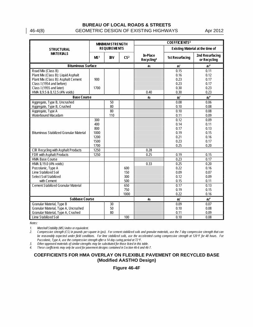
The existing structural number (SNF), an abstract number related to the strength of the total existing pavement structure, is the summation of the existing layer thicknesses multiplied by their corresponding strength coefficients from Figure 46-4F. Use the following equation to determine the existing structural number:
SNF,e = a1’D1 + a2’D2 + a3’D3 Equation 46-4.1 Where:
SNF,e = existing flexible pavement structural number a1’, a2’, and a3’ = coefficients of relative strength of the surface, base, and
subbase materials, respectively D1, D2, and D3 = thickness of the surface, base, and subbase layers,
respectively, in 46-4.02(i) Overlay Thickness Design
In determining the structural overlay thickness, the existing structural number is subtracted from the required structural number of the pavement. This needed structural number is then divided by the resurfacing coefficient to determine the resurfacing thickness. Use the following equation to determine the required overlay thickness:
O
eFFO a
SNSND
)( ,−= Equation 46-4.2
Where: DO = thickness of new HMA overlay, in
SNF = required flexible pavement structural number SNF,e = existing flexible pavement structural number aO = coefficients of relative strength of the overlay material
Typical overlays using a 19.0 mm HMA binder course and a 9.5 mm or 12.5 mm HMA surface course the coefficient of relative strength (aO) should be 0.36. If HMA surface course mixes are use the entire depth of the overlay, aO may be increased to 0.40. Contact the Central Bureau of Local Roads and Streets for other special designs. 46-4.02(j) Minimum Thickness and Material Requirements
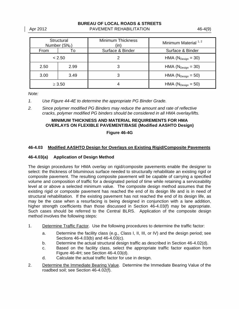
To ensure practical and adequate designs, the minimum design requirements presented in Figure 46-4G have been established. Final pavement thicknesses must comply with this table.
BUREAU OF LOCAL ROADS & STREETS 46-4(6) GEOMETRIC DESIGN OF EXISTING HIGHWAYS Apr 2012
HMA OVERLAY OVER FLEXIBLE PAVEMENT/BASE DESIGN NOMOGRAPH (Modified AASHTO Design: Class I Facilities)
Figure 46-4D

BUREAU OF LOCAL ROADS & STREETS Apr 2012 PAVEMENT REHABILITATION 46-4(7)
HMA OVERLAY ON FLEXIBLE PAVEMENT/BASE DESIGN NOMOGRAPH (Modified AASHTO Design: Class II, III, and IV Facilities)
Figure 46-4E
BUREAU OF LOCAL ROADS & STREETS 46-4(8) GEOMETRIC DESIGN OF EXISTING HIGHWAYS Apr 2012
STRUCTURAL MATERIALS
MINIMUM STRENGTH REQUIREMENTS
COEFFICIENTS3
Existing Material at the time of
MS1 IBV CS2 In-Place Recycling4 1st Resurfacing 2nd Resurfacing
or Recycling Bituminous Surface a1 a1′ a1″
Road Mix (Class B) 0.15 0.11 Plant Mix (Class B): Liquid Asphalt 0.16 0.12 Plant Mix (Class B): Asphalt Cement 900 0.23 0.17 Class I (1954 and before) 0.23 0.17 Class I (1955 and later) 1700 0.30 0.23 HMA IL9.5 & IL12.5 (4% voids) 0.40 0.30 0.23
Base Course a2 a2′ a2″ Aggregate, Type B, Uncrushed 50 0.08 0.06 Aggregate, Type B, Crushed 80 0.10 0.08 Aggregate, Type A 80 0.10 0.08 Waterbound Macadam 110 0.11 0.09
Bituminous Stabilized Granular Material
300 0.12 0.09 400 0.14 0.11 800 0.17 0.13 1000 0.19 0.15 1200 0.21 0.16 1500 0.23 0.17 1700 0.25 0.20
CIR Recycling with Asphalt Products 1250 0.28 FDR with Asphalt Products 1250 0.25 0.19 0.15 HMA Base Course 0.23 0.17 HMA IL19.0 (4% voids) 0.33 0.25 0.20 Pozzolanic, Type A 600 0.22 0.16 Lime Stabilized Soil 150 0.09 0.07 Select Soil Stabilized 300 0.12 0.09 with Cement 500 0.15 0.11 Cement Stabilized Granular Material 650 0.17 0.13 750 0.19 0.15 1000 0.22 0.16
Subbase Course a3 a3′ a3″ Granular Material, Type B 30 0.09 0.07 Granular Material, Type A, Uncrushed 50 0.10 0.08 Granular Material, Type A, Crushed 80 0.11 0.09 Lime Stabilized Soil 100 0.10 0.08
Notes: 1. Marshall Stability (MS) index or equivalent. 2. Compressive strength (CS) in pounds per square in (psi). For cement stabilized soils and granular materials, use the 7 day compressive strength that can
be reasonably expected under field conditions. For lime stabilized soils, use the accelerated curing compressive strength at 120°F for 48 hours. For Pozzolanic, Type A, use the compressive strength after a 14 day curing period at 72°F.
3. Other approved materials of similar strengths may be substituted for those listed in this table. 4. These coefficients may only be used for pavement designs contained in Section 46-6 and 46-7.
COEFFICIENTS FOR HMA OVERLAY ON FLEXIBLE PAVEMENT OR RECYCLED BASE (Modified AASTHO Design)
Figure 46-4F
BUREAU OF LOCAL ROADS & STREETS Apr 2012 PAVEMENT REHABILITATION 46-4(9)
Structural Number (SNF)
Minimum Thickness (in) Minimum Material 1, 2
From To Surface & Binder Surface & Binder
< 2.50 2 HMA (NDesign = 30)
2.50 2.99 3 HMA (NDesign = 30)
3.00 3.49 3 HMA (NDesign = 50)
≥ 3.50 4 HMA (NDesign = 50)
Note:
1. Use Figure 44-4E to determine the appropriate PG Binder Grade.
2. Since polymer modified PG Binders may reduce the amount and rate of reflective cracks, polymer modified PG binders should be considered in all HMA overlay/lifts.
MINIMUM THICKNESS AND MATERIAL REQUIREMENTS FOR HMA OVERLAYS ON FLEXIBLE PAVEMENT/BASE (Modified AASHTO Design)
Figure 46-4G 46-4.03 Modified AASHTO Design for Overlays on Existing Rigid/Composite Pavements
46-4.03(a) Application of Design Method
The design procedures for HMA overlay on rigid/composite pavements enable the designer to select: the thickness of bituminous surface needed to structurally rehabilitate an existing rigid or composite pavement. The resulting composite pavement will be capable of carrying a specified volume and composition of traffic for a designated period of time while retaining a serviceability level at or above a selected minimum value. The composite design method assumes that the existing rigid or composite pavement has reached the end of its design life and is in need of structural rehabilitation. If the existing pavement has not reached the end of its design life, as may be the case when a resurfacing is being designed in conjunction with a lane addition, higher strength coefficients than those discussed in Section 46-4.03(f) may be appropriate. Such cases should be referred to the Central BLRS. Application of the composite design method involves the following steps: 1. Determine Traffic Factor. Use the following procedures to determine the traffic factor:
a. Determine the facility class (e.g., Class I, II, III, or IV) and the design period; see Sections 46-4.03(b) and 46-4.03(c).
b. Determine the actual structural design traffic as described in Section 46-4.02(d). c. Based on the facility class, select the appropriate traffic factor equation from
Figure 46-4H; see Section 46-4.03(d). d. Calculate the actual traffic factor for use in design.
2. Determine the Immediate Bearing Value. Determine the Immediate Bearing Value of the roadbed soil; see Section 46-4.02(f).

BUREAU OF LOCAL ROADS & STREETS 46-4(10) GEOMETRIC DESIGN OF EXISTING HIGHWAYS Apr 2012 3. Determine the Structural Number (SNC). Determine the required composite pavement
structural number (SNC) using the appropriate design nomograph for the facility class (i.e., Figure 46-4I for Class I facilities or Figure 46-4J for Class II, III, and IV facilities); see Section 46-4.03(e).
4. Determine Thickness. Select the appropriate equation from Section 46-4.03(f) as follows:
• First Resurfacing: use Equation 46-4.3 • Second Resurfacing: use Equation 46-4.4
Using the appropriate equation calculate the thickness of the HMA overlay and round the thickness up to the nearest 0.25 in.
Note that these equations do not include provisions for a third resurfacing. Pavements that are in need of a third resurfacing for structural reasons often are badly deteriorated and may no longer be functioning as a rigid pavement. Contact the Central BLRS for guidance in selecting the appropriate strength coefficients for such pavements.
5. Compare with Minimum Criteria. Compare the calculated thickness with the minimum requirements presented in Figure 46-4K; see Section 46-4.03(g). Use the larger of the values for design.
46-4.03(b) Classes of Roads and Streets
The class of the road or street for which the bituminous overlay design is being determined is dependent upon the structural design traffic. These road classifications are defined in Section 44-4.01. 46-4.03(c) Design Period
The design period DP is the length of time in years that the bituminous overlay is being designed to serve the structural design traffic. For bituminous overlays, the minimum DP allowed is 15 years for Class I, II, III, and IV roads and streets. However, designers are encouraged to determine thicknesses for both 15 year and 20 year DP’s prior to selecting the final design thickness. 46-4.03(d) Traffic Factors
For Class I, II, III, and IV roads and streets, the design TF for rigid pavements is determined from the 80,000 pound load limit formulas shown in Figure 46-4H. The formulas are based on the Statewide average distribution of vehicle types and axle loadings, which are directly applicable to most roads and streets. However, cases will arise in which the average formula should not be used (e.g., a highway where HCV’s entering and leaving a site generally travel empty in one direction and fully loaded in the other). These cases should be referred to Central BLRS for special analysis. The local agency must provide Central BLRS with the structural design traffic, the DP, and traffic distribution by PV’s, SU’s, and MU’s.
BUREAU OF LOCAL ROADS & STREETS Apr 2012 PAVEMENT REHABILITATION 46-4(11)
Class I Roads and Streets
4 or 5 Lane Pavements (Rural and Urban) 0000001
MU389313SU71564PV0470DPTF,,
)...( ++=
6 or More Lane Pavements (Rural) 0000001
MU568278SU52457PV0290DPTF,,
)...( ++=
6 or More Lane Pavements (Urban) 0000001
MU675257SU21053PV0120DPTF,,
)...( ++=
One-way Street Pavements (Rural and Urban) 0000001
MU210348SU90571PV0730DPTF,,
)...( ++=
Class II Roads and Streets
2 or 3 Lane Pavements 0000001
MU605283SU89067PV0730DPTF,,
)...( ++=
Class III Roads and Streets
2 or 3 Lane Pavements 0000001MU235281SU79064PV0730DPTF
,,)...( ++
=
Class IV Roads and Streets
2 Lane Pavement 0000001
MU95277SU87563PV0730DPTF,,
)...( ++=
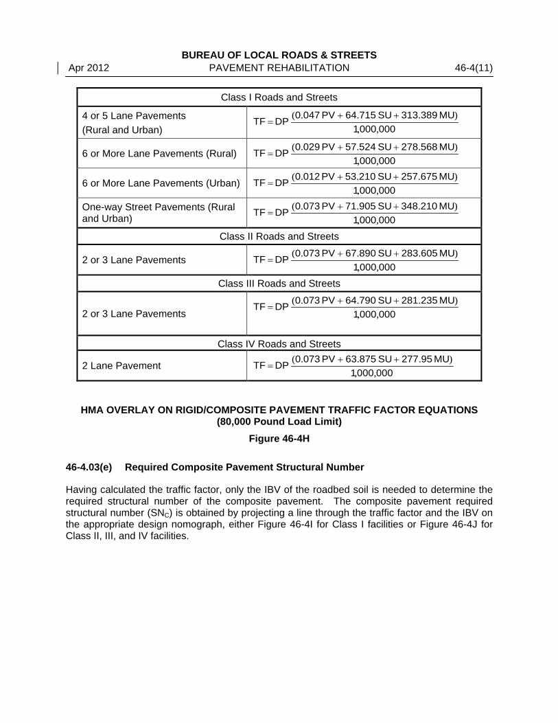
HMA OVERLAY ON RIGID/COMPOSITE PAVEMENT TRAFFIC FACTOR EQUATIONS
(80,000 Pound Load Limit) Figure 46-4H
46-4.03(e) Required Composite Pavement Structural Number
Having calculated the traffic factor, only the IBV of the roadbed soil is needed to determine the required structural number of the composite pavement. The composite pavement required structural number (SNC) is obtained by projecting a line through the traffic factor and the IBV on the appropriate design nomograph, either Figure 46-4I for Class I facilities or Figure 46-4J for Class II, III, and IV facilities.
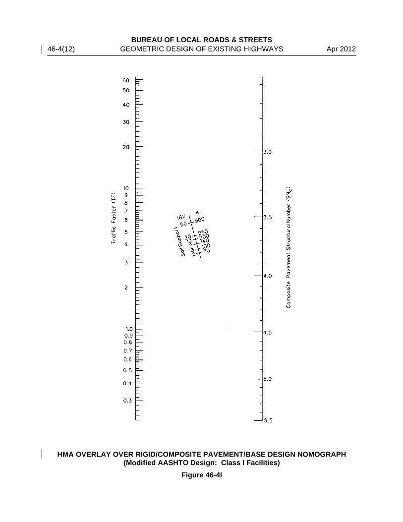
BUREAU OF LOCAL ROADS & STREETS 46-4(12) GEOMETRIC DESIGN OF EXISTING HIGHWAYS Apr 2012
HMA OVERLAY OVER RIGID/COMPOSITE PAVEMENT/BASE DESIGN NOMOGRAPH (Modified AASHTO Design: Class I Facilities)
Figure 46-4I
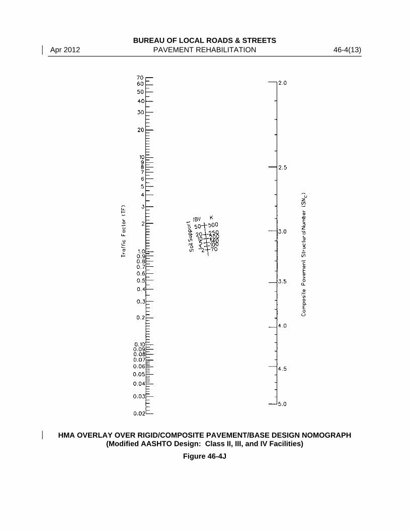
BUREAU OF LOCAL ROADS & STREETS Apr 2012 PAVEMENT REHABILITATION 46-4(13)
HMA OVERLAY OVER RIGID/COMPOSITE PAVEMENT/BASE DESIGN NOMOGRAPH (Modified AASHTO Design: Class II, III, and IV Facilities)
Figure 46-4J

BUREAU OF LOCAL ROADS & STREETS 46-4(14) GEOMETRIC DESIGN OF EXISTING HIGHWAYS Apr 2012 46-4.03(f) Thickness Design Equations
The composite pavement structural number (SNC), an abstract number related to the strength required of the total pavement structure, is a summation of layer thicknesses multiplied by their corresponding strength coefficients. Three design equations incorporate the composite pavement structural number as follows:
400D260SN
D CCO .
.−= Equation 46-4.3
400D170D250SN
D CECO .
.. −−= Equation 46-4.4
Where: SNC = composite pavement structural number
DO = thickness of new HMA overlay (in) DC = equivalent thickness of existing PCC slab (in) DE = thickness of existing HMA surface (in)
In the case of existing jointed reinforced and non-reinforced PCC pavements of uniform thickness, the equivalent thickness of the PCC slab (DC) is the actual slab thickness. For a CRC pavement, DC is the slab thickness multiplied by 1.25. 46-4.03(g) Minimum Thickness and Material Requirements
To ensure practical and adequate designs, the minimum design requirements presented in Figure 46-4K have been established. Final pavement thicknesses must comply with this table.
Structural
Number (SNC) Minimum Thickness
(in) Minimum Material
From To Surface & Binder Surface & Binder
< 2.50 2 HMA with Low ESAL’s
2.50 2.99 3 HMA with Low ESAL’s
3.00 3.49 3 HMA (4% voids)
≥ 3.50 4 HMA (4% voids)
MINIMUM THICKNESS AND MATERIAL REQUIREMENTS FOR HMA
OVERLAYS ON RIGID/COMPOSITE PAVEMENT (Modified AASHTO Design)
Figure 46-4K

BUREAU OF LOCAL ROADS & STREETS Apr 2012 PAVEMENT REHABILITATION 46-4(15) 46-4.04 Design Example
* * * * * * * * * * Example 46-4.1 Given: Existing 73,280 pound Class I Urban One-way flexible pavement in District 6 with
Slow Traffic.
The existing cross section is composed of:
• 3.0 in of Class I HMA surface,
• 12 in of Lime Stabilized Soil base, and
• 4 in of Granular Material, Type A, Crushed.
Design Traffic:
• ADT: 8900
• 94% PV (8366), 5% SU (445), 1% MU (89) Subgrade Support Rating: Poor IBV = 4
Problem: Design an HMA overlay to upgrade the route to 80,000 pounds. Solution: 1. This is a structural overlay; therefore, a pavement design procedure must be used. The
designer may choose FWD testing, modified AASHTO, or other approves design methods. This example shows the modified AASHTO approach.
2. Using Figure 46-4B, determine the TF equation for a one-way Class I pavement for a
design period of 15 years and 20 years.
One-way Streets and Pavements (Rural and Urban)
𝑇𝐹 = 𝐷𝑃 �(0.073𝑃𝑉 + 66.250𝑆𝑈 + 241.265𝑀𝑈)
1,000,000�
𝑇𝐹20 = 20 �(0.073 × 8,366 + 66.250 × 445 + 241.265 × 89)
1,000,000�
𝑇𝐹20 = 1.03
𝑇𝐹15 = 15 �(0.073 × 8,366 + 66.250 × 445 + 241.265 × 89)
1,000,000�
𝑇𝐹15 = 0.77 3. Using Figure 46-4D and the given IBV of 4, the required flexible structural number (SNF)
is 3.9 for the 20-year DP and 3.8 for the 15-year DP.
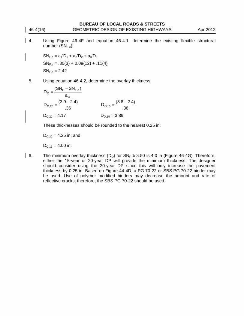
BUREAU OF LOCAL ROADS & STREETS 46-4(16) GEOMETRIC DESIGN OF EXISTING HIGHWAYS Apr 2012 4. Using Figure 46-4F and equation 46-4.1, determine the existing flexible structural
number (SNF,e):
SNF,e = a1’D1 + a2’D2 + a3’D3
SNF,e = .30(3) + 0.09(12) + .11(4)
SNF,e = 2.42 5. Using equation 46-4.2, determine the overlay thickness:
O
eFFO a
SNSND
)( ,−=
364293D 20O .
)..(,
−=
364283D 15O .
)..(,
−=
DO,20 = 4.17 DO,15 = 3.89
These thicknesses should be rounded to the nearest 0.25 in: DO,20 = 4.25 in; and DO,15 = 4.00 in.
6. The minimum overlay thickness (DO) for SNF ≥ 3.50 is 4.0 in (Figure 46-4G). Therefore, either the 15-year or 20-year DP will provide the minimum thickness. The designer should consider using the 20-year DP since this will only increase the pavement thickness by 0.25 in. Based on Figure 44-4D, a PG 70-22 or SBS PG 70-22 binder may be used. Use of polymer modified binders may decrease the amount and rate of reflective cracks; therefore, the SBS PG 70-22 should be used.

BUREAU OF LOCAL ROADS & STREETS Apr 2012 PAVEMENT REHABILITATION 46-4(17) Example 46-4.2 Given: Existing 73,280 pound Class I Urban One-way rigid pavement in District 6 with
Slow Traffic.
The existing cross section is composed of -
• 8 in of jointed non-reinforced PCC pavement, and
• 4 in of Granular Material, Type A, Crushed.
Design Traffic:
• ADT: 8900
• 94% PV (8366), 5% SU (445), 1% MU (89) Subgrade Support Rating: Poor IBV = 2
Problem: Design an HMA overlay to upgrade the route to 80,000 pounds. Solution: 1. This is a structural overlay; therefore, a pavement design must be used. The designer
may use modified AASHTO or other approved design methods. This example shows the modified AASHTO approach.
2. Use Figure 46-4H and determine the TF equation for a one-way Class I pavement for a
design period of 15 years and 20 years.
One-way Streets and Pavements (Rural and Urban)
𝑇𝐹 = 𝐷𝑃 �(0.073𝑃𝑉 + 71.905𝑆𝑈 + 348.210𝑀𝑈)
1,000,000�
𝑇𝐹20 = 20 �(0.073 × 8,366 + 71.905 × 445 + 348.210 × 89)
1,000,000�
𝑇𝐹20 = 1.27
𝑇𝐹15 = 15 �(0.073 × 8,366 + 71.905 × 445 + 348.210 × 89)
1,000,000�
𝑇𝐹15 = 0.95
3. Using Figure 46-4I and the given IBV of 2, the required flexible structural number (SNC)
is 3.3 for the 20-year DP and 3.2 for the 15-year DP.
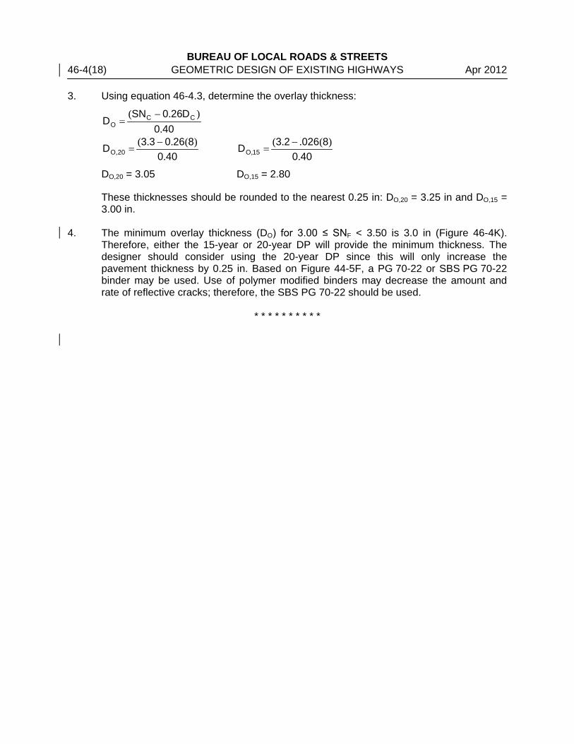
BUREAU OF LOCAL ROADS & STREETS 46-4(18) GEOMETRIC DESIGN OF EXISTING HIGHWAYS Apr 2012 3. Using equation 46-4.3, determine the overlay thickness:
400D260SN
D CCO .
).( −=
400826033D 20O .
)(..(,
−=
400802623D 15O .
)(..(,
−=
DO,20 = 3.05 DO,15 = 2.80
These thicknesses should be rounded to the nearest 0.25 in: DO,20 = 3.25 in and DO,15 = 3.00 in.
4. The minimum overlay thickness (DO) for 3.00 ≤ SNF < 3.50 is 3.0 in (Figure 46-4K). Therefore, either the 15-year or 20-year DP will provide the minimum thickness. The designer should consider using the 20-year DP since this will only increase the pavement thickness by 0.25 in. Based on Figure 44-5F, a PG 70-22 or SBS PG 70-22 binder may be used. Use of polymer modified binders may decrease the amount and rate of reflective cracks; therefore, the SBS PG 70-22 should be used.
* * * * * * * * * *

BUREAU OF LOCAL ROADS & STREETS Apr 2012 PAVEMENT REHABILITATION 46-5(1) 46-5 PCC INLAY/OVERLAY ON EXISTING ON HMA SURFACES
46-5.01 Introduction
The stopping, starting, standing, and turning actions of vehicles at intersections or other locations may create rutting and other severe conditions for pavement structures with HMA surfaces. The volume and type of vehicles may also distress HMA surfaces. Standing water in ruts (e.g., from rain events) may create a hydroplaning hazard. In addition, snow and ice left in the ruts after snowplowing may be hazardous to the traveling public. Therefore, a PCC inlay/overlay may be a better alternative than HMA. The PCC inlay/overlay has no risk for rutting and a longer service life may be achieved. A PCC inlay/overlay consists of placing a thin concrete layer on an existing HMA surface. Construction of an inlay/overlay includes milling the existing rutted HMA to correct longitudinal profile and cross-slope irregularities and providing a surface for bonding of the overlay. A PCC inlay/overlay may be considered as an alternative at intersections or other locations where HMA overlays have shown a tendency to rut or have shortened performance lives. Synthetic fibers are required where the inlay/overlay is 4.0 in. or less, and optional where it exceeds 4.0 in. The synthetic fibers currently used are much different from the fibers originally used in inlay/overlay projects. The original fibers used were mainly to prevent plastic shrinkage cracks. The new fibers will provide structural reinforcement, which will increase flexural toughness and cracking resistance. These procedures do not apply to a thickness greater than 6.0 in. which is considered an unbonded concrete inlay/overlay. 46-5.01(a) Applicability
These guidelines have been prepared for a rehabilitation strategy that involves a 3.0 in. to 6.0 in. PCC inlay/overlay bonded to a pavement structure that has an HMA surface. This rehabilitation strategy has been previously known as ultrathin whitetopping. These guidelines may be used to evaluate pavement at an existing intersection or other locations to determine if use of a PCC inlay/overlay is feasible and constructible. These guidelines also contain design steps needed to successfully complete this option. A PCC inlay/overlay requires a thorough review of the existing pavement structure, as well as close attention to utility, profile, and elevation adjustments. This technique requires a bonding action to the underlying HMA surface and multiple joints at an early age to control cracking and curling stresses within the inlay/overlay. These guidelines are to be followed to review the existing pavement structure, identify design considerations, and prepare a request for review and approval of a PCC inlay/overlay system.
BUREAU OF LOCAL ROADS & STREETS 46-5(2) PAVEMENT REHABILITATION Apr 2012 46-5.01(b) Limitations
Performance of PCC inlay/overlay sections can be variable because of the underlying pavement structure. The designer should consider the general constructability of a PCC inlay/overlay at the selected location. The existing HMA layer that is to remain in place shall be a minimum of 2.5 in. thick. If a portion of the PCC inlay/overlay in excess of 5% will be bonded directly to bare concrete, brick, or other old slabs of concrete, this rehabilitation method shall not be used. The 5% limitation is to allow for existing concrete patches or other existing pavement features. Construction is also hindered by complicated geometrics, utility obstructions, traffic demand, and condition of the existing pavement. The term PCC inlay can be defined as a very minor or no change in grade; and, as such, could limit its use in areas where profile adjustments would be limited (e.g., with existing curb and gutter sections). A PCC overlay would be used where profile grade adjustments are feasible. This alternative rehabilitation strategy shall apply to Class I, II, III, and IV pavements, but shall not be used for Federal-aid Interstates or when the traffic factor (based on the rigid pavement equations) exceeds 5.0. 46-5.02 Review of Existing Pavement Structure
A thorough investigation of the existing pavement structure should be conducted. The purpose of this investigation is to determine if the section in question is suitable for a PCC inlay/overlay. It is essential that only appropriate sections be selected for this rehabilitation option.
46-5.02(a) Preliminary Pavement Investigation
The designer should research past rehabilitation attempts as well as future plans for the area that surrounds the intersection/roadway. Research of past rehabilitation attempts will provide information on why past rehabilitation methods have not performed as designed. Insight into future plans for the pavement and area surrounding the project may influence the design of the rehabilitation. The designer should check to see if any of the limitations of this application apply. If it appears that a PCC inlay/overlay can be constructed, then a detailed pavement investigation is necessary to verify the constructability of the inlay/overlay.
46-5.02(b) Detailed Pavement Investigation
Upon completion of the preliminary investigation, a detailed pavement coring plan should be developed and administered. In general, cores will be taken to represent the majority of pavement cross sections and locations within the project. A document with guidelines for material sampling entitled “Guidelines for Material Sampling and Testing of Existing Hot Mix Asphalt Pavements and Overlays,” is available through the Bureau of Materials and Physical Research. The coring plan should be completed to specifically address the following points:
• Total pavement thickness and thickness of each layer of concrete and HMA detected.
• Condition and presence of stripping for each HMA layer.

BUREAU OF LOCAL ROADS & STREETS Apr 2012 PAVEMENT REHABILITATION 46-5(3) • Condition, compressive strength (optional), presence of D-cracking, and presence of
alkali-silica reaction for each concrete layer.
• Identification of locations where patching or alternative rehabilitations methods are recommended.
In addition to the coring plan a general inspection of the project limits should be completed. The inspection should address the following items:
• Intersection of pavement crowns (multi-leg intersections)
• Location of drop inlets
• Location of loop detectors for traffic signals
• Location of sewer manholes, water valves, and all other utility obstructions
• Location of existing surface patches
• Location of high severity distresses
• Location of HMA rutting exceeding 0.35 in (9 mm)
• Clearance for overheads 46-5.02(c) Existing and Projected Average Daily Traffic
An accurate count of the existing Average Daily Traffic (ADT) with a breakdown of percentages for passenger vehicles, single unit, and multiple unit trucks should be performed. In addition, estimates for the projected ADT and classification breakdown should be developed for the design period.
46-5.02(d) Existing Pavement Structure Report
Upon completion of coring and inspection procedures, and collection of traffic data, a report should be created to document this information. 46-5.03 Thickness Design Procedure
46-5.03(a) Classes of Roads and Streets
The class of the road or street for which the concrete inlay or overlay design is being determined is dependent upon the structural design traffic. These road classifications are defined in Section 44-1.01. 46-5.03(b) Design Period
The design period DP is the length of time in years that the concrete inlay or overlay is being designed to serve the structural design traffic. The design period for this pavement type is 15 years.
BUREAU OF LOCAL ROADS & STREETS 46-5(4) PAVEMENT REHABILITATION Apr 2012 46-5.03(c) Structural Design Traffic
The structural design traffic is the estimated ADT for the year representing one-half of the design period. For example, when the design period is 15 years, the structural design traffic will be an estimate of the ADT projected to 7.5 years after the construction date. The structural design traffic is estimated from current traffic count data obtained either by manual counts or from traffic maps published by IDOT. If PV, SU, and MU counts are not available for Class III and IV roads and streets, Figure 46-5A provides an estimate of counts that can be made from the component percentages of the total traffic.
Class of Road or Street
Percentage of Structural Design Traffic PV (%) SU (%) MU (%)
III 88 7 5 IV 88 9 3
PERCENTAGE OF STRUCTURAL DESIGN TRAFFIC
(Class III or IV) Figure 46-5A
46-5.03(d) Traffic Factor
For Class I, II, III, and IV roads and streets, the design TF for rigid pavements is determined from the 80,000 pound load limit formulas shown in Figure 46-5B. The formulas are based on the Statewide average distribution of vehicle types and axle loadings, which are directly applicable to most roads and streets. However, cases will arise in which the average formula should not be used (e.g., a highway where HCV’s entering and leaving a site generally travel empty in one direction and fully loaded in the other). These cases should be referred to Central BLRS for special analysis. The local agency must provide Central BLRS with the structural design traffic, the DP, and traffic distribution by PV’s, SU’s, and MU’s. 46-5.03(e) Joint Spacing
A key to the success of a PCC inlay or overlay is proper timing and placement of longitudinal and transverse joints. These joints are hand tooled into plastic concrete or sawed into hardened concrete to provide stress relief induced by drying shrinkage and curing of concrete. Hand tooled joints shall not be used on mainline pavement with a posted speed limit greater than 40 mph because they may not be as smooth as sawed joints, resulting in rougher ride. The joints should be laid out on a regular pattern for both longitudinal and transverse directions (to form squares) based on the spacing used to determine thickness. No skewed joints shall be allowed. Transverse and longitudinal joints should be laid out to match joints, utility obstructions, and geometrics of the existing pavement including utility cuts as much as possible in advance, recognizing that field adjustments will be required. When feasible, longitudinal joints should be laid out to avoid the wheel path areas of the traveling lanes. The layout of all transverse and longitudinal joints should be detailed on the plan sheets.

BUREAU OF LOCAL ROADS & STREETS Apr 2012 PAVEMENT REHABILITATION 46-5(5) The cost of sawing may significantly influence the cost of a PCC inlay/overlay. A thicker PCC inlay/overlay may be more economical than a thinner one because the greater thickness may allow increased joint spacing, resulting in less sawing. In addition, the use of synthetic fibers for PCC inlays/overlays greater than 4.0 in may be more economical than PCC inlays/overlays without synthetic fibers because the synthetic fibers may allow an increased joint spacing. Again, the amount of sawing is reduced.
Class I Roads and Streets
4 or 5 Lane Pavements (Rural and Urban) 0000001
MU389313SU71564PV0470DPTF,,
)...( ++=
6 or More Lane Pavements (Rural) 0000001
MU568278SU52457PV0290DPTF,,
)...( ++=
6 or More Lane Pavements (Urban) 0000001
MU675257SU21053PV0120DPTF,,
)...( ++=
One-way Street Pavements (Rural and Urban) 0000001
MU210348SU90571PV0730DPTF,,
)...( ++=
Class II Roads and Streets
2 or 3 Lane Pavements 0000001
MU605283SU89067PV0730DPTF,,
)...( ++=
Class III Roads and Streets
2 or 3 Lane Pavements 0000001MU235281SU79064PV0730DPTF
,,)...( ++
=
TF minimum = 0.5 Class IV Roads and Streets
2 or 3 Lane Pavements 1,000,000
277.950MU)SU63.875PV(0.073DPTF ++=
TRAFFIC FACTOR EQUATIONS (80,000 LB LOAD LIMIT) Figure 46-5B
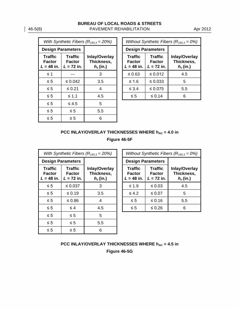
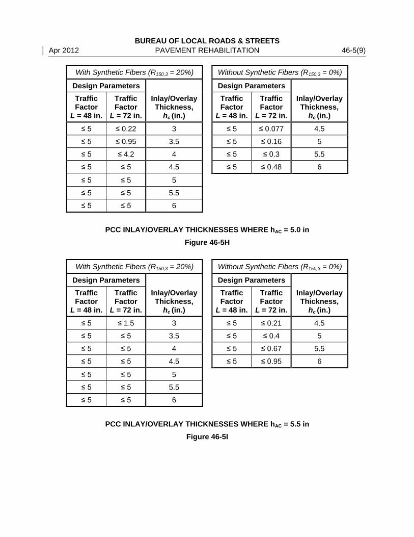
46-5.03(f) Thickness Design
Based on the traffic factor, the thickness of the underlying HMA material, panel size, and fibers/no fibers, the PCC inlay/overlay thickness may be determined either from Figures 46-5C through 46-5J or by using a computer program which is available from BDE: www.dot.il.gov/desenv/pdp.html. The inlay/overlay thickness shall be 3.0 in to 6.0 in, with 0.5 in increments allowed.
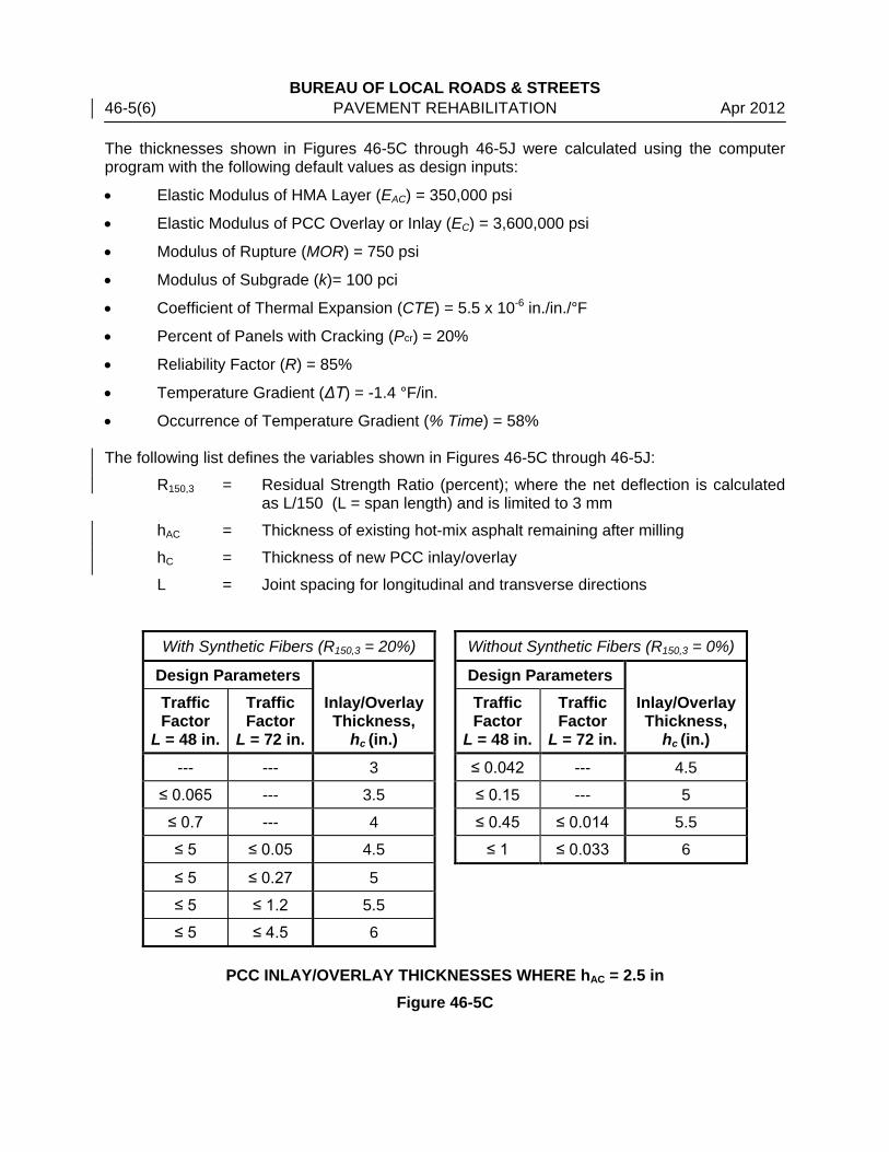
BUREAU OF LOCAL ROADS & STREETS 46-5(6) PAVEMENT REHABILITATION Apr 2012 The thicknesses shown in Figures 46-5C through 46-5J were calculated using the computer program with the following default values as design inputs:
• Elastic Modulus of HMA Layer (EAC) = 350,000 psi
• Elastic Modulus of PCC Overlay or Inlay (EC) = 3,600,000 psi
• Modulus of Rupture (MOR) = 750 psi
• Modulus of Subgrade (k)= 100 pci
• Coefficient of Thermal Expansion (CTE) = 5.5 x 10⁻⁶ in./in./°F
• Percent of Panels with Cracking (Pcr) = 20%
• Reliability Factor (R) = 85%
• Temperature Gradient (ΔT) = -1.4 °F/in.
• Occurrence of Temperature Gradient (% Time) = 58% The following list defines the variables shown in Figures 46-5C through 46-5J:
R150,3 = Residual Strength Ratio (percent); where the net deflection is calculated as L/150 (L = span length) and is limited to 3 mm
hAC = Thickness of existing hot-mix asphalt remaining after milling
hC = Thickness of new PCC inlay/overlay
L = Joint spacing for longitudinal and transverse directions
With Synthetic Fibers (R150,3 = 20%) Without Synthetic Fibers (R150,3 = 0%)
Design Parameters Design Parameters
Traffic Factor
L = 48 in.
Traffic Factor
L = 72 in.
Inlay/Overlay Thickness,
hc (in.)
Traffic Factor
L = 48 in.
Traffic Factor
L = 72 in.
Inlay/Overlay Thickness,
hc (in.)
--- --- 3 ≤ 0.042 --- 4.5
≤ 0.065 --- 3.5 ≤ 0.15 --- 5
≤ 0.7 --- 4 ≤ 0.45 ≤ 0.014 5.5
≤ 5 ≤ 0.05 4.5 ≤ 1 ≤ 0.033 6
≤ 5 ≤ 0.27 5
≤ 5 ≤ 1.2 5.5
≤ 5 ≤ 4.5 6
PCC INLAY/OVERLAY THICKNESSES WHERE hAC = 2.5 in Figure 46-5C
BUREAU OF LOCAL ROADS & STREETS Apr 2012 PAVEMENT REHABILITATION 46-5(7)
With Synthetic Fibers (R150,3 = 20%) Without Synthetic Fibers (R150,3 = 0%)
Design Parameters Design Parameters
Traffic Factor
L = 48 in.
Traffic Factor
L = 72 in.
Inlay/Overlay Thickness,
hc (in.)
Traffic Factor
L = 48 in.
Traffic Factor
L = 72 in.
Inlay/Overlay Thickness,
hc (in.)
≤ 0.025 --- 3 ≤ 0.09 --- 4.5
≤ 0.25 --- 3.5 ≤ 0.31 --- 5
≤ 2.5 ≤ 0.02 4 ≤ 0.82 ≤ 0.023 5.5
≤ 5 ≤ 0.12 4.5 ≤ 1.6 ≤ 0.05 6
≤ 5 ≤ 0.6 5
≤ 5 ≤ 2.5 5.5
≤ 5 ≤ 5 6
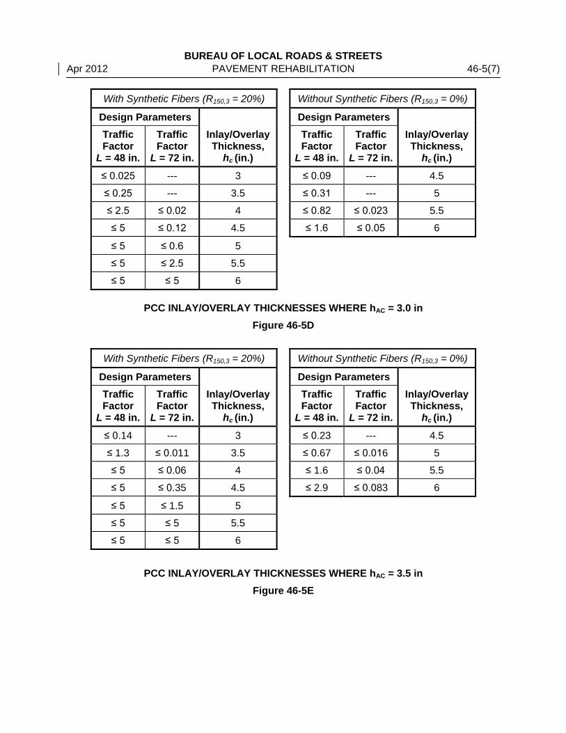
PCC INLAY/OVERLAY THICKNESSES WHERE hAC = 3.0 in Figure 46-5D
With Synthetic Fibers (R150,3 = 20%) Without Synthetic Fibers (R150,3 = 0%)
Design Parameters Design Parameters
Traffic Factor
L = 48 in.
Traffic Factor
L = 72 in.
Inlay/Overlay Thickness,
hc (in.)
Traffic Factor
L = 48 in.
Traffic Factor
L = 72 in.
Inlay/Overlay Thickness,
hc (in.)
≤ 0.14 --- 3 ≤ 0.23 --- 4.5
≤ 1.3 ≤ 0.011 3.5 ≤ 0.67 ≤ 0.016 5
≤ 5 ≤ 0.06 4 ≤ 1.6 ≤ 0.04 5.5
≤ 5 ≤ 0.35 4.5 ≤ 2.9 ≤ 0.083 6
≤ 5 ≤ 1.5 5
≤ 5 ≤ 5 5.5
≤ 5 ≤ 5 6
PCC INLAY/OVERLAY THICKNESSES WHERE hAC = 3.5 in
Figure 46-5E
BUREAU OF LOCAL ROADS & STREETS 46-5(8) PAVEMENT REHABILITATION Apr 2012
With Synthetic Fibers (R150,3 = 20%) Without Synthetic Fibers (R150,3 = 0%)
Design Parameters Design Parameters
Traffic Factor
L = 48 in.
Traffic Factor
L = 72 in.
Inlay/Overlay Thickness,
hc (in.)
Traffic Factor
L = 48 in.
Traffic Factor
L = 72 in.
Inlay/Overlay Thickness,
hc (in.)
≤ 1 --- 3 ≤ 0.63 ≤ 0.012 4.5
≤ 5 ≤ 0.042 3.5 ≤ 1.6 ≤ 0.033 5
≤ 5 ≤ 0.21 4 ≤ 3.4 ≤ 0.075 5.5
≤ 5 ≤ 1.1 4.5 ≤ 5 ≤ 0.14 6
≤ 5 ≤ 4.5 5
≤ 5 ≤ 5 5.5
≤ 5 ≤ 5 6
PCC INLAY/OVERLAY THICKNESSES WHERE hAC = 4.0 in
Figure 46-5F
With Synthetic Fibers (R150,3 = 20%) Without Synthetic Fibers (R150,3 = 0%)
Design Parameters Design Parameters
Traffic Factor
L = 48 in.
Traffic Factor
L = 72 in.
Inlay/Overlay Thickness,
hc (in.)
Traffic Factor
L = 48 in.
Traffic Factor
L = 72 in.
Inlay/Overlay Thickness,
hc (in.)
≤ 5 ≤ 0.037 3 ≤ 1.9 ≤ 0.03 4.5
≤ 5 ≤ 0.19 3.5 ≤ 4.2 ≤ 0.07 5
≤ 5 ≤ 0.86 4 ≤ 5 ≤ 0.16 5.5
≤ 5 ≤ 4 4.5 ≤ 5 ≤ 0.26 6
≤ 5 ≤ 5 5
≤ 5 ≤ 5 5.5
≤ 5 ≤ 5 6
PCC INLAY/OVERLAY THICKNESSES WHERE hAC = 4.5 in
Figure 46-5G
BUREAU OF LOCAL ROADS & STREETS Apr 2012 PAVEMENT REHABILITATION 46-5(9)
With Synthetic Fibers (R150,3 = 20%) Without Synthetic Fibers (R150,3 = 0%)
Design Parameters Design Parameters
Traffic Factor
L = 48 in.
Traffic Factor
L = 72 in.
Inlay/Overlay Thickness,
hc (in.)
Traffic Factor
L = 48 in.
Traffic Factor
L = 72 in.
Inlay/Overlay Thickness,
hc (in.)
≤ 5 ≤ 0.22 3 ≤ 5 ≤ 0.077 4.5
≤ 5 ≤ 0.95 3.5 ≤ 5 ≤ 0.16 5
≤ 5 ≤ 4.2 4 ≤ 5 ≤ 0.3 5.5
≤ 5 ≤ 5 4.5 ≤ 5 ≤ 0.48 6
≤ 5 ≤ 5 5
≤ 5 ≤ 5 5.5
≤ 5 ≤ 5 6
PCC INLAY/OVERLAY THICKNESSES WHERE hAC = 5.0 in
Figure 46-5H
With Synthetic Fibers (R150,3 = 20%) Without Synthetic Fibers (R150,3 = 0%)
Design Parameters Design Parameters
Traffic Factor
L = 48 in.
Traffic Factor
L = 72 in.
Inlay/Overlay Thickness,
hc (in.)
Traffic Factor
L = 48 in.
Traffic Factor
L = 72 in.
Inlay/Overlay Thickness,
hc (in.)
≤ 5 ≤ 1.5 3 ≤ 5 ≤ 0.21 4.5
≤ 5 ≤ 5 3.5 ≤ 5 ≤ 0.4 5
≤ 5 ≤ 5 4 ≤ 5 ≤ 0.67 5.5
≤ 5 ≤ 5 4.5 ≤ 5 ≤ 0.95 6
≤ 5 ≤ 5 5
≤ 5 ≤ 5 5.5
≤ 5 ≤ 5 6
PCC INLAY/OVERLAY THICKNESSES WHERE hAC = 5.5 in
Figure 46-5I
BUREAU OF LOCAL ROADS & STREETS 46-5(10) PAVEMENT REHABILITATION Apr 2012
With Synthetic Fibers (R150,3 = 20%) Without Synthetic Fibers (R150,3 = 0%)
Design Parameters Design Parameters
Traffic Factor
L = 48 in.
Traffic Factor
L = 72 in.
Inlay/Overlay Thickness,
hc (in.)
Traffic Factor
L = 48 in.
Traffic Factor
L = 72 in.
Inlay/Overlay Thickness,
hc (in.)
≤ 5 ≤ 5 3 ≤ 5 ≤ 0.62 4.5
≤ 5 ≤ 5 3.5 ≤ 5 ≤ 1 5
≤ 5 ≤ 5 4 ≤ 5 ≤ 1.5 5.5
≤ 5 ≤ 5 4.5 ≤ 5 ≤ 1.9 6
≤ 5 ≤ 5 5
≤ 5 ≤ 5 5.5
≤ 5 ≤ 5 6
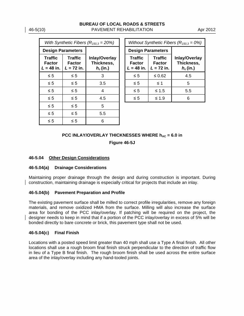
PCC INLAY/OVERLAY THICKNESSES WHERE hAC = 6.0 in
Figure 46-5J 46-5.04 Other Design Considerations
46-5.04(a) Drainage Considerations
Maintaining proper drainage through the design and during construction is important. During construction, maintaining drainage is especially critical for projects that include an inlay. 46-5.04(b) Pavement Preparation and Profile
The existing pavement surface shall be milled to correct profile irregularities, remove any foreign materials, and remove oxidized HMA from the surface. Milling will also increase the surface area for bonding of the PCC inlay/overlay. If patching will be required on the project, the designer needs to keep in mind that if a portion of the PCC inlay/overlay in excess of 5% will be bonded directly to bare concrete or brick, this pavement type shall not be used. 46-5.04(c) Final Finish
Locations with a posted speed limit greater than 40 mph shall use a Type A final finish. All other locations shall use a rough broom final finish struck perpendicular to the direction of traffic flow in lieu of a Type B final finish. The rough broom finish shall be used across the entire surface area of the inlay/overlay including any hand-tooled joints.
BUREAU OF LOCAL ROADS & STREETS Apr 2012 PAVEMENT REHABILITATION 46-5(11) 46-5.04(d) Traffic Control
The control of traffic through the project must be considered and well established prior to the time of construction. The best alternative for traffic control is to completely close the project to traffic. This alternative may be difficult for urban projects. If closure to traffic is not possible, traffic control must be established that will effectively move traffic through the project with minimal disruption to construction operations and traffic flow. Traffic control that can be left unattended overnight must be anticipated for each stage of construction. 46-5.04(e) Construction Staging
Construction staging for a PCC inlay/overlay project must be considered with respect to the construction timeframe and traffic flow through the project. The project must be staged in such a way that continuous traffic flow will be maintained. Construction staging must also consider the geometrics of the project and any lane to lane drop off restrictions that may be present with the overlay thickness. PCC inlays/overlays have a traffic opening strength of 550 psi flexural or 3,000 psi compressive. The current PCC mix design specified may obtain the opening strength in as little as three days if properly proportioned. If the inlay/overlay must be opened to traffic in a shorter time frame, consult the District Materials Office for an acceptable high-early-strength PCC mixture.
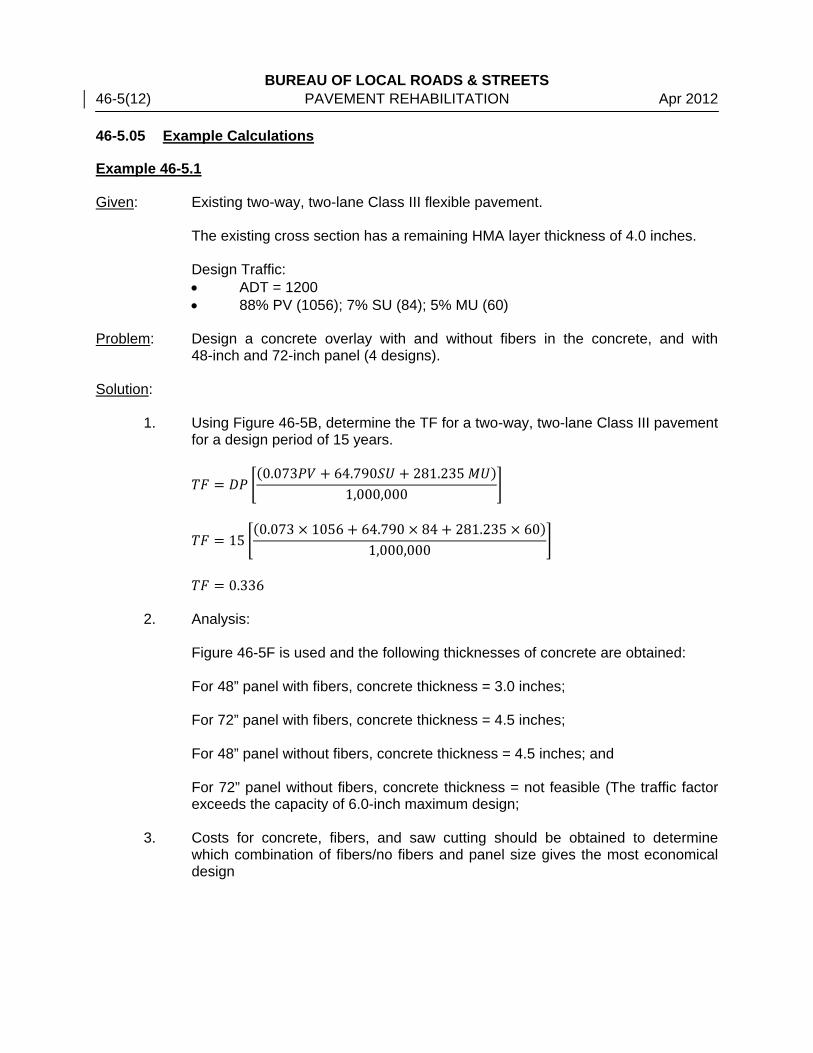
BUREAU OF LOCAL ROADS & STREETS 46-5(12) PAVEMENT REHABILITATION Apr 2012 46-5.05 Example Calculations
Example 46-5.1 Given: Existing two-way, two-lane Class III flexible pavement.
The existing cross section has a remaining HMA layer thickness of 4.0 inches. Design Traffic: • ADT = 1200 • 88% PV (1056); 7% SU (84); 5% MU (60)
Problem: Design a concrete overlay with and without fibers in the concrete, and with
48-inch and 72-inch panel (4 designs). Solution:
1. Using Figure 46-5B, determine the TF for a two-way, two-lane Class III pavement for a design period of 15 years.
𝑇𝐹 = 𝐷𝑃 �(0.073𝑃𝑉 + 64.790𝑆𝑈 + 281.235 𝑀𝑈)
1,000,000�
𝑇𝐹 = 15 �(0.073 × 1056 + 64.790 × 84 + 281.235 × 60)
1,000,000�
𝑇𝐹 = 0.336
2. Analysis: Figure 46-5F is used and the following thicknesses of concrete are obtained: For 48” panel with fibers, concrete thickness = 3.0 inches; For 72” panel with fibers, concrete thickness = 4.5 inches; For 48” panel without fibers, concrete thickness = 4.5 inches; and For 72” panel without fibers, concrete thickness = not feasible (The traffic factor exceeds the capacity of 6.0-inch maximum design;
3. Costs for concrete, fibers, and saw cutting should be obtained to determine which combination of fibers/no fibers and panel size gives the most economical design

BUREAU OF LOCAL ROADS & STREETS Apr 2012 PAVEMENT REHABILITATION 46-6(1) 46-6 FLEXIBLE PAVEMENT IN-PLACE RECYCLING
46-6.01 Introduction
Flexible pavements may be recycled using a variety of equipment, recycling agents, and processes. There are three general categories: Hot In-Place Recycling (HIR), Cold In-Place Recycling (CIR), and Full Depth Reclamation (FDR). A thorough investigation of the existing pavement structure should be conducted. The purpose of this investigation is to determine if the section in question is suitable for an in-place recycling project. It is essential that only appropriate sections be selected for this rehabilitation option. If existing pavement structure is adequate further material investigation will be needed to select recycling technique and design. Pavements with deteriorations or distresses due to subgrade or drainage problems should only be considered for in-place recycling if additional work is undertaken to correct the subgrade and drainage deficiencies. Figure 46-1A shows appropriate distresses that may be addressed using an in-place recycling treatment.
Pavement Distress In-Place Recycling Process HIR CIR FDR
Raveling Potholes Bleeding Skid Resistance Rutting Corrugations Shoving Fatigue Cracking Edge Cracking Slippage Cracking Block Cracking Longitudinal Cracking Traverse Cracking Reflective Cracking Discontinuity Cracking Ride Quality Structural Improvement
Most Appropriate
Least Appropriate
IN-PLACE RECYCLING PAVEMENT DISTRESS SELECTION
Figure 46-6A Projects developed in accordance with this section will be eligible for MFT, State, and/or Federal funding.

BUREAU OF LOCAL ROADS & STREETS 46-6(2) PAVEMENT REHABILITATION Apr 2012 46-6.02 Hot In-Place Recycling (HIR)
HIR is an on-site, in-place rehabilitation method which consists of heating, softening, scarifying, mixing, placing, and compacting 0.75 in (19 mm) to 2 in (50 mm) of the existing bituminous pavement. The following pavement distresses may be treated by HIR:
• Surface Defects (Raveling, Potholes, Bleeding, Skid Resistance)
• Permanent Deformation (Rutting, Corrugations, and Shoving)
• Slippage, Longitudinal, Transverse, and Reflective Cracking
• Ride Quality HIR may be divided into Surface Recycling, Remixing, and Repaving sub-categories. 46-6.02(a) HIR - Surface Recycling
HIR - Surface Recycling should be considered when pavement distresses are contained in the top 1 in (25 mm). Drying and heating of the existing asphalt pavement surface is performed with pre-heating units that are followed behind by a heating/scarification unit. After scarification, an asphalt modifier is applied to the scarified pavement prior to mixing, placing, and compacting the recycled pavement. After completing the HIR – Surface Recycling process, a maximum 2.0 in (50 mm) HMA surface course shall be placed. LR400-3 should be used for this work. 46-6.02(b) HIR - Remixing
HIR – Remixing should be considered when significant modification of the existing asphalt pavement is needed to correct specific pavement distresses and/or the recycled mix is to function as the wearing course. HIR – Remixing will require more in-depth investigation and mix design. HIR – Remixing may be performed as a single stage or multiple stages. Since design procedures and specifications have not been developed, HIR – Remixing needs to follow the experimental feature requirement in Section 11-3.06 of this manual. 46-6.02(c) HIR - Repaving
HIR – Repaving should be considered when other HIR processes will not restore the pavement profile or surface requirements and/or a thin HMA or specialty mix is required as a surface course. HIR – Repaving will require more in-depth investigation and mix design. HIR – Repaving may be performed as a single pass or multiple pass; however, the recycled lift and the new HMA surface course are compacted as one lift. Since design procedures and specifications have not been developed, HIR – Repaving needs to follow the experimental feature requirement in Section 11-3.06 of this manual.

BUREAU OF LOCAL ROADS & STREETS Apr 2012 PAVEMENT REHABILITATION 46-6(3) 46-6.03 Cold In-Place Recycling (CIR)
46-6.03(a) General
CIR is an on-site, in-place rehabilitation method which consists of cold milling or pulverizing, mixing with emulsified asphalt or foamed asphalt, placing, and compacting 2 in (50 mm) to 6 in (150 mm) of the existing bituminous pavement. The following pavement distresses may be treated by CIR:
• Surface Defects (Raveling, Potholes, Bleeding, Skid Resistance)
• Permanent Deformation (Rutting, Corrugations, and Shoving)
• Fatigue, Edge, and Block Cracking
• Slippage, Longitudinal, Transverse, and Reflective Cracking
• Stripping
• Ride Quality CIR of composite pavements (HMA overlays of rigid pavements) may be a more economical option than removing all HMA overlays down to bare concrete and then putting back a thick HMA overlay. However, this option is only feasible if the underlying concrete is in fairly good condition. Evidence of extensive slab movements such as pumping or differential settlement in a composite pavement may indicate potentially unstable or non-uniform subgrade support or material-related distress such as alkali-silica reactivity or D-cracking in the underlying concrete. Contact the Central Bureau of Local Roads and Streets for assistance if CIR of a composite pavement is desired. 46-6.04 Full Depth Reclamation (FDR)
46-6.04(a) General
FDR is an on-site, in-place rehabilitation method which consists of uniformly pulverizing, mixing with emulsified asphalt or foamed asphalt, placing, and compacting the full thickness of the existing bituminous pavement and/or underlying materials (base and/or subbase) at the maximum depth of 10 in (250 mm). The following pavement distresses may be treated by FDR:
• Surface Defects (Raveling, Potholes, Bleeding, Skid Resistance)
• Permanent Deformation (Rutting, Corrugations, and Shoving)
• Fatigue, Edge, and Block Cracking
• Slippage, Longitudinal, Transverse, and Reflective Cracking
• Stripping
• Ride Quality
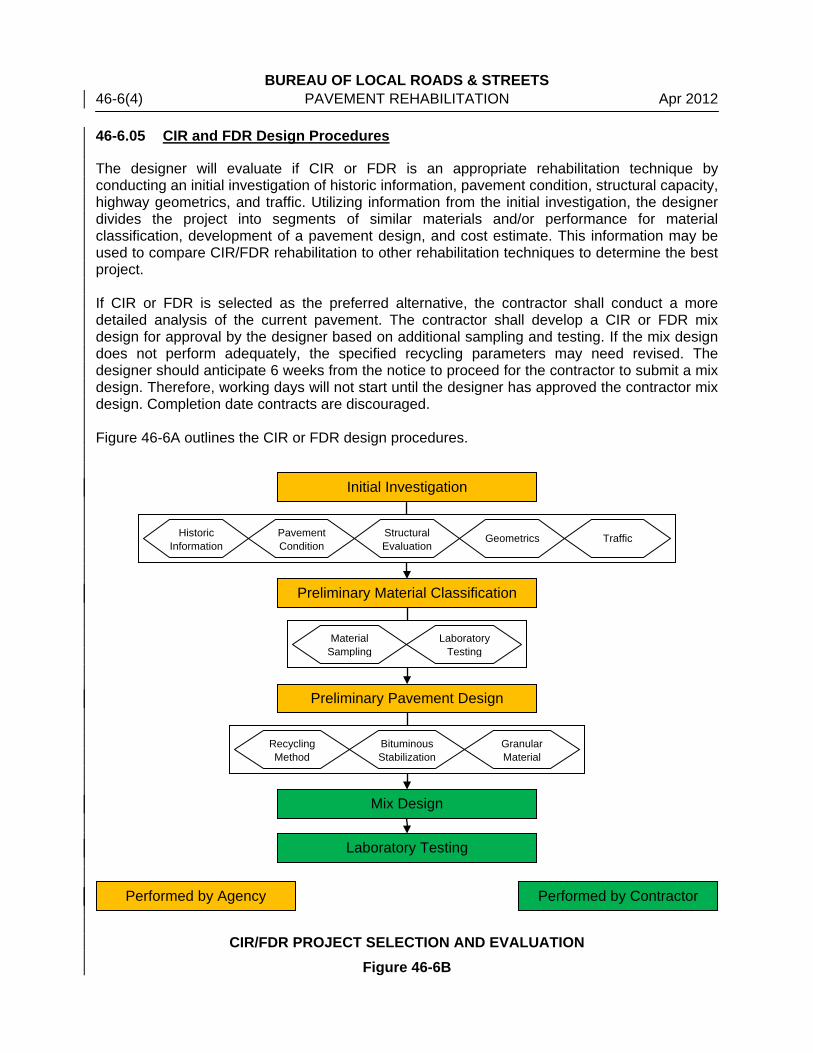
BUREAU OF LOCAL ROADS & STREETS 46-6(4) PAVEMENT REHABILITATION Apr 2012 46-6.05 CIR and FDR Design Procedures
The designer will evaluate if CIR or FDR is an appropriate rehabilitation technique by conducting an initial investigation of historic information, pavement condition, structural capacity, highway geometrics, and traffic. Utilizing information from the initial investigation, the designer divides the project into segments of similar materials and/or performance for material classification, development of a pavement design, and cost estimate. This information may be used to compare CIR/FDR rehabilitation to other rehabilitation techniques to determine the best project. If CIR or FDR is selected as the preferred alternative, the contractor shall conduct a more detailed analysis of the current pavement. The contractor shall develop a CIR or FDR mix design for approval by the designer based on additional sampling and testing. If the mix design does not perform adequately, the specified recycling parameters may need revised. The designer should anticipate 6 weeks from the notice to proceed for the contractor to submit a mix design. Therefore, working days will not start until the designer has approved the contractor mix design. Completion date contracts are discouraged. Figure 46-6A outlines the CIR or FDR design procedures.
CIR/FDR PROJECT SELECTION AND EVALUATION Figure 46-6B
Preliminary Material Classification
Initial Investigation
Preliminary Pavement Design
Mix Design
Laboratory Testing
Historic Information
Pavement Condition
Structural Evaluation
Geometrics Traffic
Recycling Method
Bituminous Stabilization
Granular Material
Material Sampling
Laboratory Testing
Performed by Agency
Performed by Contractor

BUREAU OF LOCAL ROADS & STREETS Apr 2012 PAVEMENT REHABILITATION 46-6(5)
46-6.05(a) Initial Investigation
An investigation into the design traffic, the available materials, the pavement structure and the climate should be performed. This initial investigation of the existing conditions will determine if the existing pavement conditions are suitable for the CIR/FDR since it is essential that only appropriate sections be selected for these rehabilitation options. Construction and maintenance records should be reviewed to determine variations in materials and typical pavement section.
1. Historic Information. The designer should review construction and maintenance records to determine: • Age of highway; • Thickness, age, and type of bituminous material used for each layer/treatment; • Top size and quality of aggregates for each layer/treatment; • Presence of any paving fabrics, interlayers, or unique mixes; • Patching location, age, and material used; and • Crack sealing location, age, and material used.
2. Pavement Condition. The existing pavement condition and the type, frequency, and severity of the distresses will indicate the depth and/or type of recycling needed. • CIR/FDR is best suited for pavements that are structurally sound and have well
drained bases. The CIR/FDR process destroys the existing crack pattern; however, the Designer should consider crack depth and potential for reflective cracking when determining CIR thickness.
• The presence of large or frequent patches increases the variability of the existing materials. Large full-depth patches may require a unique mix design. Furthermore, patches may indicate locations with thinner pavement structures, poor subgrade or higher groundwater which may need corrected as part of the highway rehabilitation.
• Rutting may also be corrected with CIR/FDR if the appropriate stabilizing agent(s) and/or granular materials are used and the cause of the rutting is within the recycled thickness. If rutting is the result of a weak subgrade, CIR may not be a viable option; however, FDR may still be possible if subgrade stabilization is performed after pulverization and before reclamation.
3. Structural Evaluation. The designer should evaluate the pavement to ensure the CIR/FDR project will provide sufficient structural capacity and to verify that the underlying subgrade will provide sufficient support for construction equipment and adequate compaction of recycled mixture. Criteria for CIR/FDR pavement design is discussed in Section 46-6.05(c).
4. Geometrics. The designer should perform a detailed geometric assessment. • Major realignments or drainage corrections may be difficult using CIR. The
designer may want to consider FDR or other rehabilitation techniques in these situations.
• Granular shoulders that have sufficient granular material and good subgrade may be incorporated into the CIR/FDR process to provide a uniform base course for selected surface wearing course.
BUREAU OF LOCAL ROADS & STREETS 46-6(6) PAVEMENT REHABILITATION Apr 2012
• The location and elevation of utility covers (manholes and valves) should be identified. Manholes and valves should be lowered at least 4 in (100 mm) below the CIR/FDR treatment depth. Upgrading of existing underground utilities should be completed prior to the CIR/FDR project.
• Existing pavement on structures should not be treated with the CIR/FDR process; however, structures’ condition rating and capacity should be evaluated to determine if the structures will support the CIR/FDR construction equipment.
• Most transverse or longitudinal slope corrections may be corrected by cold planning, adding new granular or RAP material, and/or using a leveling binder under the surface wearing course.
6. Traffic. The designer should determine existing and forecasted traffic patterns and volumes to determine proper traffic control during the CIR/FDR project and for developing a pavement design.
46-6.05(b) Preliminary Material Classification
The designer should use historic information and pavement condition survey to divide project into area/segments of similar material and/or performance. The frequency of sampling to ensure representative samples varies with the size of the project, the variation in pavement structure, and the variability of existing material. However, at least one sample should be taken every 1600 to 2500 ft (500 to 760 m). The laboratory testing of the in situ materials includes testing of surface, base course, subbase, and subgrade by using core sampling and/or test pits. Coring may be done using either wet or dry coring usually 6 in (150 mm) in diameter; however, coring may not allow a representative sample of aggregate subbase to be collected. Therefore, coring is not recommended if the recycling depth includes a granular layer. Test pits may also be used by means of sawing and then excavating the pavement to expose, sample and test underlying materials; however, test pits are usually more expensive, take longer, and have a significant impact on traffic than coring. Test pits do provide a larger, more representative sample than coring. Core samples should be examined to confirm historic information including pavement layers, surface treatments, specialty mixes, or geotextile paving fabrics and to identify evidence of distresses such as stripping or rutting. If test pits are used, the visual inspection should be performed using the vertical edges of the test pits. After visual inspection, samples are crushed for further testing. Representative samples from the bituminous layers being recycled will be tested to determine:
• Moisture content (if dry sampling has been used);
• Asphalt binder content (ignition or extraction); and
• Aggregate properties of bituminous layer including gradation and angularity (natural or crushed, crushed faces).
Representative samples from the granular layers being recycled will be tested to determine:
• Moisture content (if dry sampling has been used);
• Gradation and angularity (natural or crushed, crushed faces);

BUREAU OF LOCAL ROADS & STREETS Apr 2012 PAVEMENT REHABILITATION 46-6(7) • Plastic index; and
• Sand equivalent value. Figure 46-6B and Figure 46-6C provide information concerning gradations suitable for CIR and FDR using emulsified asphalt and foamed asphalt.
Sieve Size
Percent Passing
CIR/FDR with Emulsified Asphalt CIR/FDR with Foamed Asphalt
Ideal Less Suitable Ideal Less Suitable 2 in 50 mm 100 100
1 ½ in 37.5 mm 87 – 100 87 – 100 1 in 25 mm 77 – 100 100 77 – 100 100 ¾ in 19 mm 66 – 99 99 – 100 66 – 99 99 – 100 ½ in 12.5 mm 67 – 87 87 – 100 67 – 87 87 – 100 ⅜ in 9.5 mm 49 – 74 74 – 100 49 – 74 74 – 100 No. 4 4.75 mm 35 – 56 56 – 95 35 – 56 56 – 95 No. 8 2.36 mm 25 – 42 42 – 78 25 – 42 42 – 78
No. 16 1.18 mm 18 – 33 33 – 65 18 – 33 33 – 65 No. 50 300 μm 8 – 21 21 – 43 10 – 24 24 – 43
No. 200 75 μm 2 – 9 9 – 20 4 – 10 10 – 20 Note: Adapted from the 2010 Wirtgen Cold Recycling Technology guide.
GRADATION SUITABLE FOR CIR/FDR TREATMENT Figure 46-6B
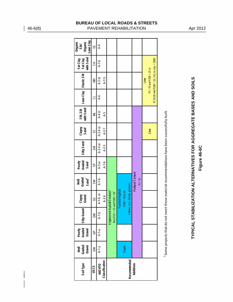
BUREAU OF LOCAL ROADS & STREETS 46-6(8) PAVEMENT REHABILITATION Apr 2012
TYPI
CA
L ST
AB
ILIZ
ATI
ON
ALT
ERN
ATI
VES
FOR
AG
GR
EGA
TE B
ASE
S A
ND
SO
ILS
Figu
re 4
6-6C
Soil T
ype
Well
Gr
aded
Gr
avel
Poor
ly Gr
aded
Gr
avel
Silty
Gra
vel
Clay
ey
Grav
el
Well
Gr
aded
Sa
nd1
Poor
ly Gr
aded
Sa
ndSi
lty S
and
Clay
ey
Sand
Silt,
Silt
wi
th S
and
Lean
Clay
Elas
tic S
iltFa
t Clay
, Fa
t Clay
wi
th S
and
Orga
nic
Silt/
Or
gani
c Le
an C
layUS
CSGW
GPGM
GCSW
SPSM
SCML
CLMH
CHOL
A-1-
aA-
1-a
A-1-
bA-
1-b
or
A-1-
bA-
3 or
A-2-
4 or
A-2-
6 or
A-4 o
rA-
6A-
5 or
A-7-
6A-
4A-
2-6
A-1-
bA-
2-5
A-2-
7A-
5A-
7-5
Foam
Lime
1 Som
e pr
ojec
ts th
at d
o no
t mee
t the
se m
ater
ial r
ecom
men
dati
ons
have
bee
n su
cces
sful
ly b
uilt
.
Lime
PI >
10
and
P200
< 2
5 or
PI 1
0-30
and
P20
0 >
25, S
O 4 in
clay
< 3
000
AASH
TO
Clas
sifica
tion
Reco
mmen
ded
Addi
tives
Engin
eere
d Asp
halt E
mulsio
n1
Best
if SE
> 25
and
P20
0 <
201
Foam
ed A
spha
ltP2
00 =
10
to 20
Follo
ws
max
den
sity
grad
ation
Portla
nd C
emen
tPI
< 1
0
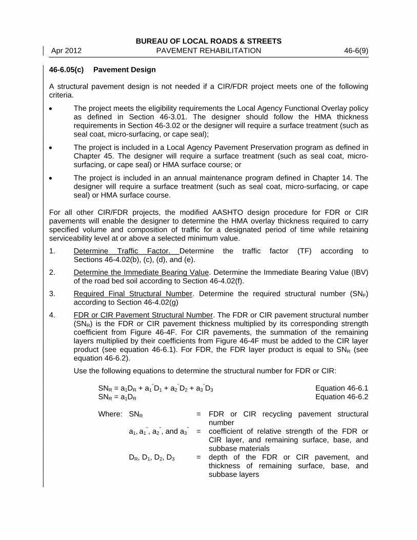
BUREAU OF LOCAL ROADS & STREETS Apr 2012 PAVEMENT REHABILITATION 46-6(9) 46-6.05(c) Pavement Design
A structural pavement design is not needed if a CIR/FDR project meets one of the following criteria.
• The project meets the eligibility requirements the Local Agency Functional Overlay policy as defined in Section 46-3.01. The designer should follow the HMA thickness requirements in Section 46-3.02 or the designer will require a surface treatment (such as seal coat, micro-surfacing, or cape seal);
• The project is included in a Local Agency Pavement Preservation program as defined in Chapter 45. The designer will require a surface treatment (such as seal coat, micro-surfacing, or cape seal) or HMA surface course; or
• The project is included in an annual maintenance program defined in Chapter 14. The designer will require a surface treatment (such as seal coat, micro-surfacing, or cape seal) or HMA surface course.
For all other CIR/FDR projects, the modified AASHTO design procedure for FDR or CIR pavements will enable the designer to determine the HMA overlay thickness required to carry specified volume and composition of traffic for a designated period of time while retaining serviceability level at or above a selected minimum value.
1. Determine Traffic Factor. Determine the traffic factor (TF) according to Sections 46-4.02(b), (c), (d), and (e).
2. Determine the Immediate Bearing Value. Determine the Immediate Bearing Value (IBV) of the road bed soil according to Section 46-4.02(f).
3. Required Final Structural Number. Determine the required structural number (SNF) according to Section 46-4.02(g)
4. FDR or CIR Pavement Structural Number. The FDR or CIR pavement structural number (SNR) is the FDR or CIR pavement thickness multiplied by its corresponding strength coefficient from Figure 46-4F. For CIR pavements, the summation of the remaining layers multiplied by their coefficients from Figure 46-4F must be added to the CIR layer product (see equation 46-6.1). For FDR, the FDR layer product is equal to SNR (see equation 46-6.2).
Use the following equations to determine the structural number for FDR or CIR:
SNR = a1DR + a1’’D1 + a2
’’D2 + a3’’D3 Equation 46-6.1
SNR = a1DR Equation 46-6.2 Where: SNR = FDR or CIR recycling pavement structural
number a1, a1
’’, a2’’, and a3
’’ = coefficient of relative strength of the FDR or CIR layer, and remaining surface, base, and subbase materials
DR, D1, D2, D3 = depth of the FDR or CIR pavement, and thickness of remaining surface, base, and subbase layers

BUREAU OF LOCAL ROADS & STREETS 46-6(10) PAVEMENT REHABILITATION Apr 2012 5. Overlay Thickness Design. If SNR ≥ SNF, a HMA overlay is not required; however, the
pavement shall be covered with a surface treatment such as seal coat, micro-surfacing, or cape seal.
If SNR < SNF, a HMA overlay thickness (DO) is required. In determining the HMA overlay thickness, the in-place recycling pavement structural number is subtracted from the required structural number of the pavement. This needed structural number is then divided by the resurfacing coefficient to determine the resurfacing thickness.
Use the following equation to determine the required HMA overlay thickness:
O
RFO a
)SNSN(D −= Equation 46-4.2
Where: DO = thickness of new HMA overlay, in SNF = required flexible pavement structural number SNR = FDR pavement structural number aO = coefficients of relative strength of the overlay material
For typical overlays using a 19.0 mm HMA binder course and a 9.5 mm or 12.5 mm HMA surface course, the coefficient of relative strength of the overlay material (aO) should be 0.36. If HMA surface course mixes are use the entire depth of the overlay, aO may be increased to 0.40. Contact the Central Bureau of Local Roads and Streets for other special designs.
46-6.05(d) Determination of Project Criteria
The designer will use the initial investigation, preliminary material classification, and pavement design to establish project segments and depth of recycling; to select the type of recycling process (CIR or FDR) and bituminous stabilization agent (foamed asphalt or emulsified asphalt); and to determine if additional granular material is needed. The designer will use LR400-4, LR400-5, LR400-6, or LR400-7 as the contract special provision and included copies of the material testing in the contract documents. 46-6.05(e) Mix Design
The designer will require the contractor to submit a mix design meeting the performance criteria for asphalt emulsion (see Figure 46-6D) or foamed asphalt (see Figure 46-6E) stabilization. The designer will provide at least six weeks from the notice to proceed date for the contractor to perform the mix design. Depending on mix design results, the structural pavement design may need altered and/or additional laboratory testing performed. The mix design varies somewhat depending on whether engineered asphalt emulsion or foamed asphalt is used as a stabilizing agent. Regardless of the bituminous stabilization used, the mix design should contain the following:
• Determine suitability of reclaimed material and necessary additives (coarse aggregate, fine aggregate, cement, fly ash, etc.);
• Establish optimum moisture content and optimum fluid content;
• Determine optimum bitumen content; and
• Confirm mechanical properties of the mix

BUREAU OF LOCAL ROADS & STREETS Apr 2012 PAVEMENT REHABILITATION 46-6(11)
Test Method CIR FDR Type 1 1 FDR Type 2 2 Test Purpose
Superpave Gyratory Compaction, 1.25° angle, 600 kPa
30 gyrations at 4 in
(100 mm) 3
30 gyrations at 6 in
(150 mm)
30 gyrations at 6 in
(150 mm)
Laboratory Density Indicator
Modified Proctor, ASTM D1557, Method C N/A Report Report Optimum Moisture
Design Moisture Content Report Report Report Dispersion of Emulsion
Bulk Specific Gravity (Density), ASTM D 6752 or ASTM D2726 Report Report Report Laboratory Density
Indicator Rice (Maximum Theoretical) Specific Gravity, ASTM D2041 Report Report Report Laboratory Density
Indicator
Air Voids, Modified Report Report Report Laboratory Density Indicator
Marshall Stability, ASTM D 1559, lbs
1,250 3 minimum N/A N/A Stability Indicator
Retained Stability 70% minimum N/A N/A Moisture Damage
Resistance
Raveling Test, ASTM D 7196 2% maximum N/A N/A Raveling Resistance
Sand Equivalent, ASTM D 2419, Method B N/A Report Report
Modified Proctor, ASTM D 1557, Method C N/A Report Report
Optimum Moisture Content for Density
and Compaction Short Term Strength (STS), ASTM D 1560, Part 13, 175 g/25 mm of width
N/A 175 minimum 150 minimum Stability Indicator
Indirect Tensile Strength, ASTM D 4867, psi N/A 40 minimum 35 minimum Strength Indicator
Conditioned Indirect Tensile Strength, ASTM D 4867, psi N/A 25 minimum 20 minimum
Gradation for Design Millings, AASHTO T 27 Report Report Report
Additional Additive(s) 4
Coarse Aggregate Fine Aggregate RAP Fly Ash Cement 5
Report Report Report Report Report
Report Report Report Report Report
Report Report Report Report Report
Emulsified Asphalt 4
Distillation Residue, % Residue Penetration, dmm Optimum Emulsion Content, % Residual Asphalt to Cement
Content Ratio 5
Report Report Report Report
Report Report Report Report
Report Report Report Report
Notes: 1. FDR Type 1 mixtures contain < 8% passing No. 200. 2. FDR Type 2 mixtures contain ≥ 8% passing No. 200 or for all granular mixtures. 3. If 6 in (150 mm) samples are used, the Marshall Stability is required to be 2,500 lbs minimum. 4. Report shall include type/gradation and producer/supplier. 5. Cement Content shall be a maximum of 1.0 %. The residual asphalt content to cement content ratio shall be 3:1.
CIR/FDR ASPHALT EMULSION MIX DESIGN REQUIREMENTS
Figure 46-6D

BUREAU OF LOCAL ROADS & STREETS 46-6(12) PAVEMENT REHABILITATION Apr 2012 Test Method CIR FDR Test Purpose Gradation for Design Millings, AASHTO T 27 Report Report Plasticity Index < 10 < 10
Modified Proctor, ASTM D1557, Method C Report Report
Optimum Moisture Content and
Maximum Dry Density for Density
and Compaction
Design Moisture Content Report Report Dispersion of Emulsion
Foamed Asphalt Expansion Ratio 1 8 minimum 8 minimum Measurement of Foamed Asphalt
Viscosity
Foamed Asphalt Half-life, s 6 minimum 6 minimum Measurement of Foamed Asphalt
Stability Optimum Foamant Water Content Report Report Marshall Density, AASHTO T245
(IL Modified), blows 75 75 Laboratory Density Indicator
Bulk Specific Gravity (Density), ASTM D 6752 or ASTM D2726 Report Report Laboratory Density
Indicator Rice (Maximum Theoretical) Specific Gravity,
ASTM D2041 Report Report Laboratory Density Indicator
Air Voids Report Report Laboratory Density Indicator
Indirect Tensile Strength, AASHTO T283 (IL Modified), Dry, psi Wet (Conditioned), psi Tensile Strength Ratio (TSR), %
45 minimum 30 minimum
70%
45 minimum 30 minimum
70%
Strength Indicator
Raveling Test, 10ºC and 50% Humidity 2% maximum N/A Raveling Resistance
Additional Additive(s) 2
Coarse Aggregate Fine Aggregate RAP Fly Ash Cement
Report Report Report Report
1.0% maximum
Report Report Report Report
1.0% maximum
Asphalt Binder 2
PG Grade Penetration, dmm
Report Report
Report Report
Notes: 1. If the ambient temperature at the time of construction is expected to be 50°F to 77°F (10°C to 25°C) the foamed expansion ratio should be increased to 10.
2. Report shall include type/gradation and producer/supplier.
CIR/FDR FOAMED ASPHALT MIX DESIGN REQUIREMENTS Figure 46-6E

BUREAU OF LOCAL ROADS & STREETS Jan 2012 PAVEMENT REHABILITATION 46-7(1) 46-7 RUBBLIZATION
See Section 54-5.03 of the Bureau of Design & Environment Manual.

BUREAU OF LOCAL ROADS & STREETS 46-7(2) PAVEMENT REHABILITATION Jan 2012

BUREAU OF LOCAL ROADS & STREETS Apr 2012 PAVEMENT REHABILITATION 46-8(1) 46-8 RESOURCES
1. Guide for Design of Pavement Structures, American Association of State Highway and Transportation Officials, 1993
2. Basic Asphalt Recycling Manual, Asphalt Recycling and Reclaiming Association, 2001
3. Research Report FHWA-ICT-08-016 Design and Concrete Material Requirements for Ultra-Thin Whitetopping, Illinois Center for Transportations, 2008
4. Research Report FHWA-ICT-09-036 Cold In-Place Recycling and Full-Depth Recycling with Asphalt Products, Illinois Center for Transportation, 2009
5. Technical Guideline: Bitumen Stabilised Materials (A Guideline for the Design and Construction of Bitumen Emulsion and Foamed Bitumen Stabilised Materials), Asphalt Academy, 2009
6. Wirtgen Cold Recycling Technology, Wirtgen GmbH, 2010

BUREAU OF LOCAL ROADS & STREETS 46-8(2) PAVEMENT REHABILITATION Apr 2012