Embed Size (px)
Citation preview

C H A P T E RT W E L V E
Chipseal Failuresand Repairs

Previous page: Chipsealing in progress on State Highway 73, west of Arthur’s Pass. One of the reasons forthe chipseal was to repair the lightly flushed existing surface seen on the left of the road. This photo wastaken in high summer, as indicated by the flowering rata trees. It is also the best time for sealing.
Photo courtesy of Les McKenzie, Opus
Chap t e r 12 Ch i p s e a l Fa i l u r e s and R epa i r s
12.1 Background ___________________________________________________________________________________________________________________461
12.2 Texture Loss__________________________________________________________________________________________________________________461
12.2.1 Chip Re-orientation__________________________________________________________________________________________________462
12.2.2 High Binder Application ____________________________________________________________________________________________462
12.2.3 Chip Embedment _____________________________________________________________________________________________________462
12.2.4 Binder Rise ______________________________________________________________________________________________________________463
12.2.5 Flushing ___________________________________________________________________________________________________________________464
12.2.6 Bleeding___________________________________________________________________________________________________________________465
12.3 Chip Loss ______________________________________________________________________________________________________________________466
12.3.1 Causes of Chip Loss _________________________________________________________________________________________________466
12.3.2 Types of Chip Loss ___________________________________________________________________________________________________467
12.3.3 Extent of Chip Loss __________________________________________________________________________________________________467
12.4 Other Failure Modes ______________________________________________________________________________________________________468
12.5 Remedial Treatments ______________________________________________________________________________________________________469
12.6 Treatments for Localised Failures ____________________________________________________________________________________470
12.6.1 Water Blasting _________________________________________________________________________________________________________470
12.6.2 Gritting ___________________________________________________________________________________________________________________471
12.6.3 Hot Chip Treatment _________________________________________________________________________________________________471
12.6.4 Diluent and Chip______________________________________________________________________________________________________472
12.6.5 Sandwich Sealing ______________________________________________________________________________________________________474
12.6.6 Wet Lock ________________________________________________________________________________________________________________475
12.6.7 Removal of Remaining Chip_______________________________________________________________________________________476
12.7 Treatments for Major Area-wide Failures _________________________________________________________________________476
12.7.1 General ___________________________________________________________________________________________________________________476
12.7.2 Use of Fabrics __________________________________________________________________________________________________________476
12.7.3 Open Graded Mixes _________________________________________________________________________________________________477
12.7.4 Granular Overlay _____________________________________________________________________________________________________477
12.7.5 Dig Out and Replace ________________________________________________________________________________________________478
12.7.6 Recycle____________________________________________________________________________________________________________________478
12.8 Reseals at Short Notice__________________________________________________________________________________________________479
12.8.1 General ___________________________________________________________________________________________________________________479
12.8.2 Unscheduled Skid Resistance Restoration __________________________________________________________________479
12.8.3 Prevention of Progressive Chip Loss __________________________________________________________________________480
12.9 Conclusion ____________________________________________________________________________________________________________________481
12.10 References ____________________________________________________________________________________________________________________482
12
461C h i p s e a l i n g i n N e w Z e a l a n d
Chapter 12 Chipseal Failures and Repairs
12 . 1 Ba c k g r oundThe intent of this chapter is to describe those seal failures that occur soon after the
construction of new reseals, and to identify their causes. As well it includes suggestions
for their repairs that will give satisfactory results and, where appropriate, will enable the
design life of a particular seal coat type to be achieved. It does not include seal performance
and seal life which are covered in Chapter 4, or pre-reseal repairs which are covered in
Chapter 7.
Even though the design and construction principles outlined in the preceding chapters
may have been followed, post-sealing failures do occur and faults do develop. The type
or cause of a failure must be identified, and an appropriately timed treatment decided
on and applied. Otherwise a failed seal can develop which will require significant and
expensive repairs. This chapter does not deal with all the symptoms that appear during
the life of a chipseal as it deteriorates. For example, this discussion does not include
cracking or layer instability (covered in Chapters 6 and 7).
This chapter only deals with failures that can be corrected through a treatment that is
designed to correct the deficiency, instead of renewing the seal. Apart from unscheduled
reseals required at short notice (Section 12.8), reseals are not covered in this chapter.
12 . 2 Tex t u r e L o s sTexture loss and cracking, as discussed in Chapter 4, are the main causes of seal failure.
Seal failures by texture loss can include:
• premature binder rise;
• flushing;
• bleeding;
• chip loss;
• chip rollover; and
• pavement structural failures.
If these are treated appropriately and promptly, the surface often can continue to function
as intended.
Some of the factors that contribute to loss of texture include:
• chip re-orientation so that the height of the chip decreases;
• overspraying, which results in too much bitumen;
12
462 C h i p s e a l i n g i n N e w Z e a l a n d
• chip embedment as chip is pushed down into the substrate;
• binder rise around the chip;
• chip crushing and breakdown during construction, thus reducing effective chip ALD
(over-chipping can also cause this) (see Figure 11-3);
• long-term consolidation (not just post-construction) of the layer caused by the
tyre–seal interaction stresses;
• further chip embedment caused by the action of vehicle tyres in periods of high
temperature.
12 . 2 . 1 Ch i p R e - o r i e n t a t i o n
If, after the seal has been designed and constructed correctly, higher than expected
traffic volumes occur, flushing could be the expected failure mechanism at the
end of its design life. This means the seal will flush in the wheelpaths before the
binder has hardened and leads to texture loss by chip embedment, wearing of the
chip, etc. (see discussion in Section 4.3).
12 . 2 . 2 H i g h B i n d e r App l i c a t i o n
Premature flushing occurs when the binder application is too high for the traffic
volume. This can be caused by design or construction error. It can also occur
where the existing surface varies in texture or hardness.
To avoid flushing in wheelpaths the seal design often has to be a compromise between
an application rate that suits the wheelpaths, with some possible chip loss elsewhere
(between and outside the wheelpaths), and an application rate that suits most of the
road. There is some discussion on this topic in Section 9.4.5. Controlled trafficking
during the first few days can be used to compact chip on areas outside wheelpaths,
discussed briefly in Sections 9.10.3.3 and 11.4.1. Early chip loss can be repaired relatively
easily but a flushed surface is more difficult and expensive to repair. Chapter 9 discusses
the design philosophy for such situations.
12 . 2 . 3 Ch i p Embedmen t
Soft substrate and chip embedment are regular causes of flushing and so are taken
into account in seal design (Section 9.4.1).
12
463C h i p s e a l i n g i n N e w Z e a l a n d
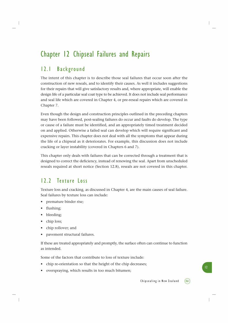
Figure 12-1 Small holes are evidence of binder rise through the action of vapour venting (volcanoes)(see also Figure 4-20). Photo courtesy of Les McKenzie, Opus
If chip embedment is greater than normal, it may be caused by presence of softer
substrates associated with:
• first coat seals;
• fresh asphaltic concrete;
• new grader-laid asphalt, or OGEMs (open graded emulsion mix);
• repairs to poorly constructed and weak pavements, or poorly constructed repairs;
• a pavement weakened by water;
• a pavement flushed with a binder-rich surface;
• a soft pavement caused by build-up of successive seals with an excess of bitumen
>12% by weight.
An outline of the effects of soft substrate is given in Section 4.7.4.1.
12 . 2 . 4 B i n d e r R i s e
Binder rise is a natural action which occurs over the life of a chipseal and can
cause flushing and bleeding (Figure 12-1). Some researchers believe that the chips
are pushed into the binder rather than the binder rises over the chips. In fact
both can happen.

12
464 C h i p s e a l i n g i n N e w Z e a l a n d
Figure 12-2 Bleeding in progress. Photo courtesy of Mark Owen, Transit NZ
Read Section 4.7.4 and its subsections which describe the principal causes of binder rise
and how it leads to flushing.
12 . 2 . 5 F l u s h i n g
Flushing occurs as a result of high binder rise and reduces the macrotexture of
the road surface until it is so low that it meets one or more of the definitions of
flushing given in Section 3.11.6.
If flushing is left untreated:
• safety issues associated with low macrotexture can arise, e.g. extended braking
distances in the wet at speed (as discussed in Section 4.9.3.1);
• when the flushed binder has low viscosity in hot weather, bleeding and tracking
(Figure 12-2) with associated safety issues can occur (as discussed in Section 12.2.6
below);
• further binder rise can occur, exacerbating the above problems and requiring costly
repairs.
12
465C h i p s e a l i n g i n N e w Z e a l a n d
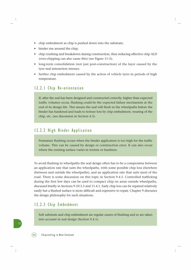
Figure 12-3 A surface showing both bleeding and tracking on a hot summer day, possibly caused by anold repair patch. This has caused the current chipseal to flush and bleed.
Photo courtesy of Les McKenzie, Opus
12 . 2 . 6 B l e e d i n g
As mentioned above, and discussed in Section 3.11.7, binder rise can result in
bleeding (Figure 12-2) which occurs when the surface tension of the binder is
broken and tracking can occur (Figure 12-3).
The pavement need not be flushed in order for it to bleed as truck tyres indent up to
1.5 mm into a seal as shown in Figure 9-12, and discussed in Section 9.9.3.3. This
mechanism helps to explain why a seal with a good texture can suddenly blacken because
binder has been picked up from a surface of seemingly high texture.
It is important to note that a flushed surface may not bleed if the binder is hard
enough, the temperature is cold enough, or the binder is contaminated with fines
from the road surface.

12
466 C h i p s e a l i n g i n N e w Z e a l a n d
If bleeding is not treated promptly,
• tracking occurs with associated safety issues (e.g. low skid resistance because the
microtexture is masked);
• extensive damage to the seal may occur (e.g. heavy or slow moving vehicles have been
observed pulling out tyre-width sections of seal, sometimes down to basecourse depth);
• the blackened surface absorbs heat, and will become hotter than the original seal by
10°C or more. This hotter surface can exacerbate the problem leading to widespread
bleeding along the pavement.
12 . 3 Ch i p L o s s
Repairs are essential for a new seal that shows areas of chip loss, to retain seal
integrity and to prevent the areas from expanding into a major surfacing problem.
Surplus chip from chip loss by stripping becomes a safety issue and can result in loss-of-control crashes, broken windscreens, injury to the general public from flying chip,and general damage to other road users.
12 . 3 . 1 C au s e s o f Ch i p L o s sChip loss can occur for a number of reasons which are listed here.
• Low binder application rates.
• Traffic stress, e.g. from high speed, turning, high volumes, or increased heavy trafficvolume during the seal’s life.
• Cold weather affecting binder characteristics, e.g. sealing in late summer, coldovernight temperatures.
• Wet weather affecting binder characteristics during and after sealing.
• Lack of diluent or adhesion agent.
• Sealing over poorly constructed pre-reseal repairs.
• Cold binder.
• Fretting of the upper chip layer of a two coat seal.
• Dirty chip (Figure 12-4).
• Binder oxidation.
• Stop-start traffic, particularly on up or downhill sections of roads, e.g. rubbish truckson urban streets.
• Heavy braking and acceleration.
• Scuffing, e.g. using power steering in parking lanes.

12
467C h i p s e a l i n g i n N e w Z e a l a n d
Figure 12-4 Chip loss caused by dirty chip in the seal. Photo courtesy of Les McKenzie, Opus
12 . 3 . 2 Typ e s o f Ch i p L o s s
The three main types of chip loss are:
• Stripping, which occurs generally along wheelpaths, in long strips.
• Attrition, in which the chips are worn away by friction.
• Scabbing, which is chip loss from patches of chipseal.
Some chip loss occurs soon after construction and is related to construction deficiencies,
e.g. dirty chip, lack of adhesion agent, excess traffic speeds during or soon after
construction. Further chip loss can occur during normal service or if rain falls immediately
after sealing.
12 . 3 . 3 E x t e n t o f Ch i p L o s s
Chip loss or stripping can range from light chip loss between wheelpaths and on the
centreline to extensive loss across both traffic lanes.
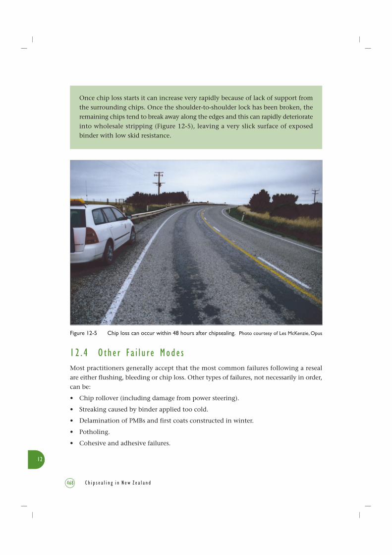
Figure 12-5 Chip loss can occur within 48 hours after chipsealing. Photo courtesy of Les McKenzie, Opus
12
468 C h i p s e a l i n g i n N e w Z e a l a n d
Once chip loss starts it can increase very rapidly because of lack of support from
the surrounding chips. Once the shoulder-to-shoulder lock has been broken, the
remaining chips tend to break away along the edges and this can rapidly deteriorate
into wholesale stripping (Figure 12-5), leaving a very slick surface of exposed
binder with low skid resistance.
12 . 4 O t h e r Fa i l u r e Mode sMost practitioners generally accept that the most common failures following a reseal
are either flushing, bleeding or chip loss. Other types of failures, not necessarily in order,
can be:
• Chip rollover (including damage from power steering).
• Streaking caused by binder applied too cold.
• Delamination of PMBs and first coats constructed in winter.
• Potholing.
• Cohesive and adhesive failures.
12
469C h i p s e a l i n g i n N e w Z e a l a n d
Causes of these failures include:
• Construction faults, such as blocked jets and height of spraybar which cause irregular
streaky application of the bitumen.
• Failed pre-reseal repairs.
• Poorly repaired digouts and base failures.
• Increase in heavy traffic loading.
• Diluent content too high.
• Low bitumen application rates.
• Shaded cooler areas, e.g. beneath over-bridges, structures, trees, etc.
12 . 5 R emed i a l Tr e a tmen t sFor future reseals, and to eliminate as many of the failures outlined in Sections 12.2 and
12.3 as possible, finding out why a new seal has failed and then choosing the correct
method to repair the problem is very important.
It is not uncommon to see a very flushed and sometimes bleeding seal just before the
start of a brand new seal that has been tracked on to the new seal. There the additional
binder film on the new seal can cause further bleeding and tracking problems.
Stripping or chip loss can be caused by dirty chip which is not necessarily accompanied
by binder deficiency.
Good seal design can be achieved by using harder binders where climate permits,
minimising diluent content, not sealing in cold temperatures, and if necessary using a
PMB. Remember that although using a PMB may prevent bleeding and tracking, it will
not prevent flushing. These principles should also be used in deciding the appropriate
repair methods.
The design life of repairs should at least equal the design life of the original seal
coat. But preventing the problem is better than having to treat it. For example,
if the failure mode is a flushed or bleeding section of seal which is being tracked
down the road, the first priority is to treat the source of the problem to prevent
further tracking.
Obviously a good seal design for the original seal coat to avoid stripping or chip
loss is preferred, rather than repairing a seal.
12
470 C h i p s e a l i n g i n N e w Z e a l a n d
In determining the appropriate treatment for a flushed area, it is essential to keep
in mind the mechanism that caused the problem.
For example, in a flushed pavement, the cause is layer instability if the problem is a
high binder:stone ratio (described in Section 4.7.4.2). For this problem, water blasting
is not cost-effective and is only a temporary fix. See Section 6.5.5 and subsections for
the analysis and treatment of layer instability.
If rain after sealing is the cause of a stripped pavement in which binder is not deficient,
a hot-rolled chip may work. But if the cause was dirty chip, then hot-rolled chip may
not work because the original binder is probably contaminated with too much dust.
Treatments can be divided into:
• Treatments for localised failures: can include high pressure water treatment, hot chip,
diluent and chip, sandwich sealing, wet lock, and small digouts.
• Treatments for area-wide major failures: where significant or severe loss in design life
has occurred, repairs can include the use of fabric (geotextile), open graded mixes,
granular overlay, digout and replace, and recycling.
These treatments should be expected to restore the integrity of the pavement surface
so that subsequent resealing will last at least as long as the normal design life.
Sometimes the expensive fix is more productive than repeatedly using a high risk
cheaper option that is likely to fail. If too much binder is present throughout the
layers of chipseals, the best option may be to strip off all the seals (i.e. an Area-wide
Pavement Treatment (AWPT) discussed in Section 12.7), or recycle the pavement,
because under some conditions a surfacing treatment will be all but impossible to
get right.
12 . 6 Tr e a tmen t s f o r L o c a l i s e d Fa i l u r e s
12 . 6 . 1 Wa t e r B l a s t i n g
Water blasting (high pressure water treatment) was trialled in New Zealand in the late
1990s (Figure 7-11) and has rapidly replaced the pavement burner as a method of
removing excess binder and the pavement burner is now banned (see p.250).
The different types of high pressure water treatments that are available are outlined in
Section 7.3.4.2.
12
471C h i p s e a l i n g i n N e w Z e a l a n d
All high pressure water treatment units are operator-dependent and care should
be taken to avoid removing too much binder.
If binder has been pushed up to the surface by vapour pressure and it is then removed,
the binder that is left may not be enough to hold the chip, and result in chip loss or
loss of waterproofing.
Water blasting cannot be used on first coat seals, and is high risk even with two-coat-
as-first-coat seals. There is a certain binder:stone ratio above which water blasting will
not be effective (see Section 6.5.5.3).
12 . 6 . 2 G r i t t i n g
In the past, common practice has been to lay grit or sand on a flushed chipseal.
This is no longer encouraged as field observations have regularly shown that the
sand fills the voids between the chips, pushing the bitumen even higher, and
making the flushing worse.
For example, Figure 7-12 shows a flushed surface which has been aggravated by gritting
(on the left of the photo). A depth of about 5 mm flushed binder was successfully
removed in this case by high pressure water treatment, restoring the texture as shown
on the right of the photo.
12 . 6 . 3 Ho t Ch i p Tr e a tmen t
The hot chip technique can only be used to treat localised areas where chip loss
has occurred, and is usually used when the binder is still soft and a bond can be
easily obtained. As such it can be used for the early treatment of construction
faults. An advantage of this system is that less diluent or cutter is needed which
minimises the risk of future flushing.
Hot chip (often precoated) is obtained from a hot mix asphalt plant. The production
temperature depends on the haul distance between plant and job but is normally in the
range of 160–190°C. If the chip is precoated the temperature should not be allowed to
rise above about 170°C. Above this temperature the precoating bitumen could oxidise
too rapidly and, if kept at such high temperatures, the equivalent of 1 to 2 years ageing
can occur in a matter of hours.
12
472 C h i p s e a l i n g i n N e w Z e a l a n d
If uncoated hot chip seems to have a significant quantity of dust, and even though the
chip may have a high cleanness value, the dust source could be the hot mix asphalt
plant. If so, the plant must be checked to ensure that the drum or pug mill have been
well cleaned.
Hot chip can be used by itself (without binder) when enough excess binder remains on
the road. However it will not work where the in-situ binder, although enough, is
contaminated with fines.
Hot chip can also be used with an application of binder, usually with cutback, or an
emulsion binder. In some circumstances emulsion could be the preferred choice as it
is more suited to lower application rates than hot bitumen. If extra binder is applied,
use only the minimum required so that the repair does not flush as a result of excess
binder.
For hot chip, the choice of chip grade depends on the existing underlying chip, traffic
stress, and quantity of excess binder. Grades 4, 5 or 6 can be used where no extra binder
is required. To ensure full embedment of the chip into the binder, it should always be
rolled.
Repair of chip loss on older chipseals is covered in Section 7.3.4.1. Another option for
repair is diluent and chip, as described below.
12 . 6 . 4 D i l u e n t and Ch i p
The application of a solvent to a flushed seal or to a seal that is showing chip loss,
and then applying chip, is a technique that has been widely used in New Zealand
as a localised treatment. The choice of solvent has often been kerosene, as mineral
turpentine has a lower flash point and is thus a greater safety hazard. The
application rate of the solvent is usually between about 0.1-0.3 /m2, and can be
applied with a sprayer (Figure 12-6). Adhesion agent may also be required in the
solvent mix.
When using diluent and chip, the size of the chip is typically two grades finer than the
existing chip (see Figure 12-7). The chip chosen will depend on the quantity of excess
binder, and the size of the underlying existing chip. The aim is to get the chip to lock
between the existing chips. Grades 4, 5 and 6 are the most common sizes used although
Grade 3 has been used at some sites. To improve the success rate of this process precoated
chips should be used.

Figure 12-6 Solvent (e.g. kerosene) being applied before it is covered with chip.Photo courtesy of Mark Owen, Transit NZ
Figure 12-7 Repair of chip loss using diluent and chip.
Application of diluent, e.g. kerosene
Partly stripped Grade 2 sealOriginal seal binderBasecourse
Area of chip loss
Chip to be level withoriginal seal
Grade 4 repair chip
Partly stripped sealOriginal seal binder
Basecourse
Area of chip lossGrade 4 repair chip
12
473C h i p s e a l i n g i n N e w Z e a l a n d
12
474 C h i p s e a l i n g i n N e w Z e a l a n d
Diluent and chip should be applied when the air temperature is at least 18°C, and
preferably in sunny weather, to ensure that the pavement temperature is as high as
possible.
This treatment should be regarded as a relatively high-risk temporary treatment because
chip loss can occur. It can also be regarded as a texturing treatment before a reseal. The
newly spread chip should always be rolled.
Care needs to be taken in choosing this treatment when any evidence is seen of past
flushing. Adding kerosene to the surface modifies the viscoelastic properties of the binder
near the surface, and not all the kerosene evaporates off. This could mean acceleration
or exacerbation of longer term flushing problems in future surfacing treatments.
12 . 6 . 5 S andw i c h S e a l i n g
Sandwich seal treatment is appropriate for areas that have flushed through trapped
water vapour pressure or chip embedment. It can also be used in place of a
texturiser and reseal if the underlying chipseals are stable. It is not advocated for
use where the underlying chip seals are unstable.
The sandwich seal technique originated in France and has been used in New Zealand
(especially the Napier region) since 1995. It essentially consists of the following
construction sequence:
1. large chip (lowest layer);
2. binder;
3. small chip (in surface layer).
Depending on the site a light tack coat of binder can be applied before the first chip.
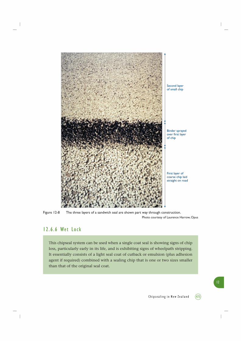
As the binder application rate is only approximately 2/3rd of the binder used for a
conventional two coat seal, a sandwich seal (Figure 12-8) has the capacity to absorb
excess binder that may exist in the failed seal. Although some seals have used a PMB,
successful treatments have been constructed with 80/100 and 130/150 penetration grade
bitumens. This design is discussed in Sections 3.7.10 and 9.7.3.
Sandwich sealing has also been used successfully on areas of high stress. As most major
roading contractors are now familiar with the technique it can be regarded as a proven
treatment but it depends on the design application rate of binder for its success. This
system has also been used successfully in the South Island for flushing in wheelpaths.
12
475C h i p s e a l i n g i n N e w Z e a l a n d
1 2 . 6 . 6 We t L o c k
This chipseal system can be used when a single coat seal is showing signs of chip
loss, particularly early in its life, and is exhibiting signs of wheelpath stripping.
It essentially consists of a light seal coat of cutback or emulsion (plus adhesion
agent if required) combined with a sealing chip that is one or two sizes smaller
than that of the original seal coat.
Figure 12-8 The three layers of a sandwich seal are shown part way through construction.Photo courtesy of Laurence Harrow, Opus
Second layerof small chip
Binder sprayedover first layerof chip
First layer ofcoarse chip laidstraight on road
12
476 C h i p s e a l i n g i n N e w Z e a l a n d
Care needs to be taken with the application rate used for a wet lock to avoid flushing.
For example if using a Grade 5 chip, the residual binder application rate would be
expected to be somewhere between 0.5 /m2 and 0.8 /m2.
Binder enrichment coats may be an option for older seals where the binder is hardening
and chip loss is starting, especially if traffic has increased since it was first constructed.
12 . 6 . 7 R emova l o f R ema i n i n g Ch i p
In an extreme case of stripping where a high percentage of chip has come off, the
removal of the remaining chip by grader or similar means should be considered,
and a new seal should be designed that makes allowance for the residual binder
that will be present.
12 . 7 Tr e a tmen t s f o r Ma j o r A r e a -w i d e Fa i l u r e s
12 . 7 . 1 Gen e r a l
Details of most of the treatments listed below are supplied in Chapter 7 and other
chapters. However, for information and assistance in decision making, a brief outline
is given here as well.
12 . 7 . 2 U s e o f Fab r i c s
A fabric (or geotextile) can be used on a flushed surface. As the fabric has the
ability to absorb binder, estimating the quantity of binder to apply so that the
binder is sufficient to hold the chipseal as well as to saturate the fabric is very
difficult.
The procedure (see Figures 3-25 and 3-26) is to:
• design an application for a tack coat that will account for the excess binder on the
existing flushed surface;
• reduce the application rate if appropriate to allow absorption of the excess binder;
• apply the tack coat over the existing surface;
• apply fabric;
• apply new seal.
12
477C h i p s e a l i n g i n N e w Z e a l a n d
The problem to be avoided is reducing the binder rates too much so that insufficient
binder is available to hold the new seal. In such cases, the chip would be expected to
be lost at the beginning of winter.
The design for fabric (geotextile) seals is outlined in Chapter 9 and described in Chapter 3.
Some local authorities are reporting success with the technique, but further research is
required before it should be regarded as a useful treatment.
12 . 7 . 3 Open G r ad ed M i xe s
Open Graded Mixes, e.g. Open Graded Porous Asphalt (OGPA), are a very effective
technique for the treatment of flushed areas (Figure 3-23). They are however
relatively expensive. Of the mix types that are readily available, the TNZ P/11
high strength ‘HS mix’ would be the most appropriate.
TNZ P/11 HS mix is a 14 mm maximum-size mix with about 15% air voids. When laid
to 25 mm thickness, a void capacity of 3.75 /m2 will result, which is well in excess of
the capacity required for absorbing excess binder. The resulting surface texture is
appropriate for high-speed areas requiring high macrotexture depths.
The grading of the HS mix is denser than the other materials in the TNZ P/11 specification
and has been found to be resistant to high traffic stresses. This material could be expected
to have a life of at least 10 years. A point to note is that the drainage capacity of the
Open Graded Mix (OGM) will not function fully because the voids are filled (or partially
filled) with excess binder from the underlying flushed surface.
12 . 7 . 4 G r anu l a r Ov e r l ay
A granular overlay is a layer of granular material (particle size greater than 0.6 mm
sand according to TNZ M/4 specification), constructed on top of an existing
pavement (to improve its shape or increase its strength). A new first coat seal is
then constructed on top of the granular overlay.
In an extreme case where a seal has failed because a build-up of multiple seal layers
has resulted in an unstable layer, a granular overlay (designed in accordance with
Austroads 2004) as an area treatment may be a cost-effective option.
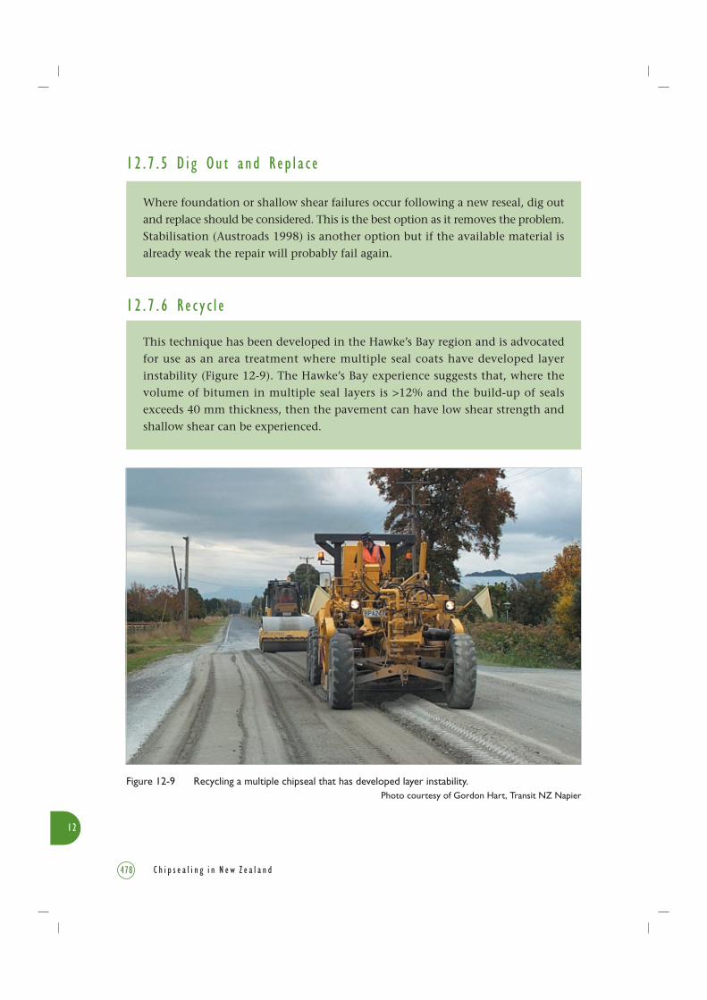
Figure 12-9 Recycling a multiple chipseal that has developed layer instability.Photo courtesy of Gordon Hart, Transit NZ Napier
12
478 C h i p s e a l i n g i n N e w Z e a l a n d
1 2 . 7 . 5 D i g Ou t and R ep l a c e
Where foundation or shallow shear failures occur following a new reseal, dig out
and replace should be considered. This is the best option as it removes the problem.
Stabilisation (Austroads 1998) is another option but if the available material is
already weak the repair will probably fail again.
12 . 7 . 6 R e c y c l e
This technique has been developed in the Hawke’s Bay region and is advocated
for use as an area treatment where multiple seal coats have developed layer
instability (Figure 12-9). The Hawke’s Bay experience suggests that, where the
volume of bitumen in multiple seal layers is >12% and the build-up of seals
exceeds 40 mm thickness, then the pavement can have low shear strength and
shallow shear can be experienced.

12
479C h i p s e a l i n g i n N e w Z e a l a n d
However, trigger points for layer instability have been shown by research (Gray & Hart
2003) to be different in different regions. Therefore it is important to investigate and
establish layer instability trigger points for the roads locally (see also Section 6.5.5.3).
The recycling technique consists of:
• milling the seal coat and the flushed seal layers;
• milling the underlying basecourse, if necessary;
• incorporating cement;
• adding extra aggregate if necessary.
The treated material is then:
• re-laid;
• compacted; and
• sealed.
A full description of the technique is available in Austroads Asphalt Recycling Guide (1997).
Depending on the availability of aggregate in some areas, a granular overlay can be more
cost-effective than recycling. This is the case for many South Island roads.
Sometimes the ‘Do nothing’ option can be taken because its minimum impact is better
than a remedial treatment which could worsen the situation. The best approach is to
consider each area case by case.
12 . 8 R e s e a l s a t S h o r t No t i c e
12 . 8 . 1 Gen e r a l
One of the purposes of a Pavement Management Strategy (PMS) is to ensure that the
RCA (Road Controlling Authority) receives an early warning of a possible need for a
reseal, allowing time for adequate preparation, investigation and design. In spite of this
precaution, in a few circumstances an unscheduled reseal may need to be carried out
at very short notice. These are described below.
12 . 8 . 2 Un s c h edu l e d S k i d R e s i s t a n c e R e s t o r a t i o n
Many RCAs have a system of regular inspections and monitoring of the skid resistance
of their roads. The most heavily trafficked roads are more likely to suffer from reduced
skid resistance and the likelihood of crashes occurring on them is greater. These roads
are generally checked annually, but the RCA may choose a reduced frequency for minor
roads. This system should give plenty of warning of potential loss of skid resistance.
12
480 C h i p s e a l i n g i n N e w Z e a l a n d
However should the system fail for whatever reason, and an old surface is below the
Threshold Level of skid resistance (as defined in TNZ T/10:2002 specification), prompt
action is essential.
Transit’s policy on rectifying low skid resistance is contained in TNZ T/10. All
RCAs should have their own formal policy on how to identify low skid resistance,
and the Austroads Skid Resistance Guide (2005) provides advice on developing a
Skid Resistance policy. Research is currently being undertaken on skid resistance
measurements which may have an effect on these policies.
Note however that a simple reseal is not necessarily the automatic solution to a skid
resistance problem. Repairing problems as identified by SCRIM do not always need a
new reseal. Instead water blasting may be sufficient to remove surface contamination,
e.g. from rubber build-up, while water cutting may be used to correct microtexture
deficiencies. (The length of time that the microtexture improvement is effective after
these treatments is the subject of a current Transfund study.)
12 . 8 . 3 P r e v e n t i o n o f P r og r e s s i v e Ch i p L o s s
A more common reason for requiring an urgent reseal is the development of chip loss.
Chip loss typically occurs either:
• in the first winter after sealing, when the binder is cold and brittle, and the chip has
still not been fully compacted by traffic; or
• late in the life of the seal, when the binder is brittle with age, and its volume has
been reduced by oxidation.
Initially only a few chips will be missing. The loss of these few chips however seriously
weakens the shoulder-to-shoulder bracing of the chips, which is as important as the grip
of the binder in holding the chip in place. The result is more chip loss that further
weakens the seal. In any road with significant traffic, the whole process can progress
from 1% or 2% loss to complete chip loss over half or more of the surface in a matter
of weeks or even less.
Maintenance crews must be trained to be alert to chip loss and report it to the
asset manager or supervisor. The initial failures may be at a poor seal joint where
there is not enough binder, or at some other localised failure, rather than a seal-
wide problem. Initial chip loss needs to be checked urgently, and in severe
conditions, a reseal may need to be applied within days.

12
481C h i p s e a l i n g i n N e w Z e a l a n d
A voidfill may appear to be a good solution and, in fact, will hold together seal areas
that are still mostly intact. However if the seal has already suffered significant chip loss,
a voidfill cannot improve already bald areas.
Rectification of the bald patches will be difficult and costly and cannot easily be achieved
in winter conditions. This is a compelling reason for quick action when the chip loss
is first observed in its early stages. Section 7.3.4.1 gives a discussion of the options for
rectifying these problems.
12 . 9 Con c l u s i o nAlthough this chapter is about repairing a chipseal because it has failed, it is also about
its re-birth or rejuvenation. Even when a pavement fails, and comes to the end of its
life, a rehabilitation or reconstruction is possible which will begin the life cycle of the
pavement once again. So, although Chapter 12 may be at the end of this book it is not
about an end but rather gives a signal that a beginning is about to start.
12
482 C h i p s e a l i n g i n N e w Z e a l a n d
1 2 . 10 R e f e r e n c e s
Austroads. 1997. Asphalt recycling guide. Austroads Publication No. AP-44/97. Austroads,
Sydney, NSW.
Austroads. 1998. Guide to stabilisation in roadworks. Austroads Publication No. AP60/98.
Austroads, Sydney, NSW.
Austroads. 2004. Pavement Design – A guide to the structural design of road pavements.
Austroads Publication No. AP-G17/04. Austroads, Sydney, NSW.
Austroads. 2005. Guidelines for the management of road surface skid resistance. Austroads
Publication No. AP-G83/05. 116pp. Austroads, Sydney, NSW.
Gray, W.J., Hart, G.J. 2003. Recycling of chipsealed pavements – New Zealand experience
in combating top surface layer instability issues. Paper presented to PIARC World Road
Congress, Durban, South Africa, September 2003.
Transit New Zealand. 2002. Specification for skid resistance investigation and treatment
selection. TNZ T/10:2002.
Transit New Zealand. 2003. Specification for basecourse aggregate. TNZ M/4:2003.
Transit New Zealand. 2003. Specification for open graded porous asphalt. TNZ P/11:2003.

![The effect of incorporating various reinforcement …failures in complete or partial dentures.[5] According to a survey conducted by Darbar et al. on the causes of repairs involving](https://img.pdfslide.us/doc/110x75/5f7b68014131535aa8154517/the-effect-of-incorporating-various-reinforcement-failures-in-complete-or-partial.jpg)