Embed Size (px)
Citation preview
A-2-i
CHAPTER A-2
Revised July 2020
STRUCTURAL
INDEX
2.1 GENERAL
2.1.1 Mission and Function
2.1.2 Scope
2.2 APPLICABLE PUBLICATIONS
2.2.1 American Association of State Highway and Transportation Officials (AASHTO)
2.2.2 American Concrete Institute (ACI)
2.2.3 American Society for Testing and Materials (ASTM)
2.2.4 American Society of Civil Engineers (ASCE)
2.2.5 American Institute of Steel Construction (AISC)
2.2.6 International Code Council (IBC)
2.2.7 American Wood Council
2.2.8 Unified Facilities Criteria (UFC)
2.2.9 Guide Specifications
2.2.10 Structural Related Guide Specifications
2.3 PRECONCEPT SUBMITTAL REQUIREMENTS
2.4 CODE 3 DESIGN REQUIREMENTS
2.4.1 Submittal
2.5 CONCEPT (35%) DESIGN SUBMITTAL REQUIREMENTS
2.5.1 Structural Narrative
2.5.2 Concept Design Analysis
2.5.3 Structural System Comparative Selection Analysis
2.5.4 Concept Drawings
2.5.5 Outline Specifications
2.5.6 Specific Instructions
2.6 PRELIMINARY (OVER THE SHOULDER) (60%) SUBMITTAL REQUIREMENTS
2.6.1 Submittal
2.7 PRELIMINARY (60%) DESIGN SUBMITTAL REQUIREMENTS
2.7.1 Preliminary Design Analysis
2.7.2 Preliminary Drawings
2.7.3 Preliminary Specifications
2.8 FINAL (100%) DESIGN SUBMITTAL REQUIREMENTS
2.8.1 Design Analysis
2.8.2 Drawings
2.8.3 Specifications
2.8.4 Quality Assurance
A-2-ii
2.9 CORRECTED FINAL DESIGN SUBMITTAL REQUIREMENTS
2.9.1 General
2.9.2 Design Analysis
2.9.3 Drawings
2.10 ADDITIONS OR MODIFICATIONS TO EXISTING STRUCTURES
2.10.1 New Work
2.10.2 Inspection Report
2.10.3 Seismic or Wind Upgrade
2.11 SITE ADAPTS OF GOVERNMENT DESIGNS
2.11.1 Concept
2.11.2 Final Design
2.12 GENERAL DESIGN REQUIREMENTS
2.12.1 Technical Requirements
2.12.2 Design Analysis
2.13 REQUIREMENTS FOR DESIGN/BUILD RFP PACKAGES
2.14 TECHNICAL REQUIREMENTS
2.14.1 General Structural Requirements
2.14.2 Design Loads
2.14.3 Structural Steel
2.14.4 Steel Joists
2.14.5 Concrete Design
2.14.6 Standing Seam Metal Roof
2.14.7 Concrete Masonry
2.14.8 Timber Trusses
2.14.9 Foundation Design
2.14.10 Building Slab on Grade Design
2.14.11 Building Frame Design Considerations
2.14.12 Seismic Design Considerations
2.14.13 Miscellaneous Structures
2.14.14 Fire Walls
APPENDIX: EXHIBITS
A-2-1 Wind Velocities and Seismic Spectral Accelerations at Local Installations
A-2-2 General Notes (For Information Only)
A-2-3 Concept (35%) Design Brochure Outline
A-2-4 Structural Section Quality Control Checklist for Review of A-E Final Design

A-2-1
CHAPTER A-2
STRUCTURAL
2.1 GENERAL
2.1.1 Mission and Function. The structural engineer is responsible for the investigation, design,
and selection of the force resisting and load supporting members and their connections in a
structure. Typical examples are foundations, walls, columns, slabs, girders, trusses, beams,
diaphragms, and similar members. The investigation, design, and selection requires a knowledge
of engineering laws, formulae, and practice; a knowledge of the physical properties of the
materials used for such members; and a knowledge of the methods used in their erection.
2.1.2 Scope. This chapter states criteria, requirements, and guidance for structural design.
Specific submittal requirements contained in this chapter supplement the requirements contained
elsewhere in other volumes. All required documents, including the drawings and the design
analysis, shall be prepared in accordance with applicable instructions. The Exhibits referenced in
this chapter are located in Volume II, Chapter 2, STRUCTURAL.
2.2 APPLICABLE PUBLICATIONS
The publications listed below, referred to hereafter by basic designation only, form a part of this
manual and contain criteria to be used in the structural design. The publications can be separated
into two divisions: industry publications (AASHTO, ACI, ASTM, ASCE, AISC, IBC, and NDS) and
government publications (Unified Facilities Criteria, or UFC). UFC publications may be accessed
from the Whole Building Design Guide website: www.wbdg.org. In the case that UFC publications
are For Official Use Only (FOUO), they may be accessed from the Protective Design Center
website after registering for an account: www.pdc.usace.army.mil.
The applicable version of all UFC publications shall be the most recent version at the time the
contract is awarded. The applicable version of industry publications shall be established using
UFC 1-200-01, General Building Requirements. Additionally, UFC 1-200-01 describes how
industry publications shall be modified by UFC publications.
The applicable version of industry and government publications shall include all addendums,
supplements, and changes. This section is not intended to be an exhaustive listing of all
publications that may be required for a particular project; additional criteria may be applicable.
2.2.1 American Association of State Highway and Transportation Officials (AASHTO)
AASHTO LRFD Bridge Design Specifications
2.2.2 American Concrete Institute (ACI)
ACI 318 Building Code Requirements for Structural Concrete
ACI 315 Details and Detailing of Concrete Reinforcement
ACI 308R Guide to Curing Concrete
ACI 360R Guide to Design of Slabs-on-Ground
ACI 530 Building Code Requirements and Specification for Masonry Structures

A-2-2
2.2.3 American Society for Testing and Materials (ASTM)
ASTM A36 Standard Specification for Carbon Structural Steel
ASTM A184 Standard Specification for Welded Deformed Steel Bar Mats for Concrete
Reinforcement
ASTM A325 Standard Specification for Structural Bolts, Steel, Heat Treated, 120/105 ksi
Minimum Tensile Strength
ASTM A572 Standard Specification for High-Strength Low-Alloy Columbium-Vanadium
Structural Steels
ASTM A615 Standard Specification for Deformed and Plain Carbon-Steel Bars for
Concrete Reinforcement
ASTM A992 Standard Specification for Structural Steel Shapes
ASTM F1554 Standard Specification for Anchor Bolts, Steel, 33, 55, and 105-ksi Yield
Strength
2.2.4 American Society of Civil Engineers (ASCE)
ASCE 7 Minimum Design Loads for Buildings and Other Structures
2.2.5 American Institute of Steel Construction (AISC)
AISC 360 Specification for Structural Steel Buildings
AISC 341 Seismic Provisions for Structural Steel Buildings
SCM Steel Construction Manual
2.2.6 International Code Council (IBC)
IBC International Building Code
2.2.7 American Wood Council
NDS National Design Specification for Wood Construction
2.2.8 Unified Facilities Criteria
UFC 1-200-01 General Building Requirements
UFC 3-301-01 Structural Engineering
UFC 3-310-04 Seismic Design for Buildings
UFC 3-310-08 Non-Expeditionary Bridge Inspection, Maintenance, and Repair
UFC 3-320-06A Concrete Floor Slabs on Grade Subjected to Heavy Loads
UFC 3-320-07N Weight Handling Equipment
UFC 3-340-01 Design and Analysis of Hardened Structures to Conventional Weapons
Effects (FOUO)
UFC 3-340-02 Structures to Resist the Effects of Accidental Explosions
UFC 3-710-01A Code 3 Design with Parametric Estimating
UFC 4-010-01 DoD Minimum Antiterrorism Standards for Buildings
UFC 4-023-03 Design of Buildings to Resist Progressive Collapse
A-2-3
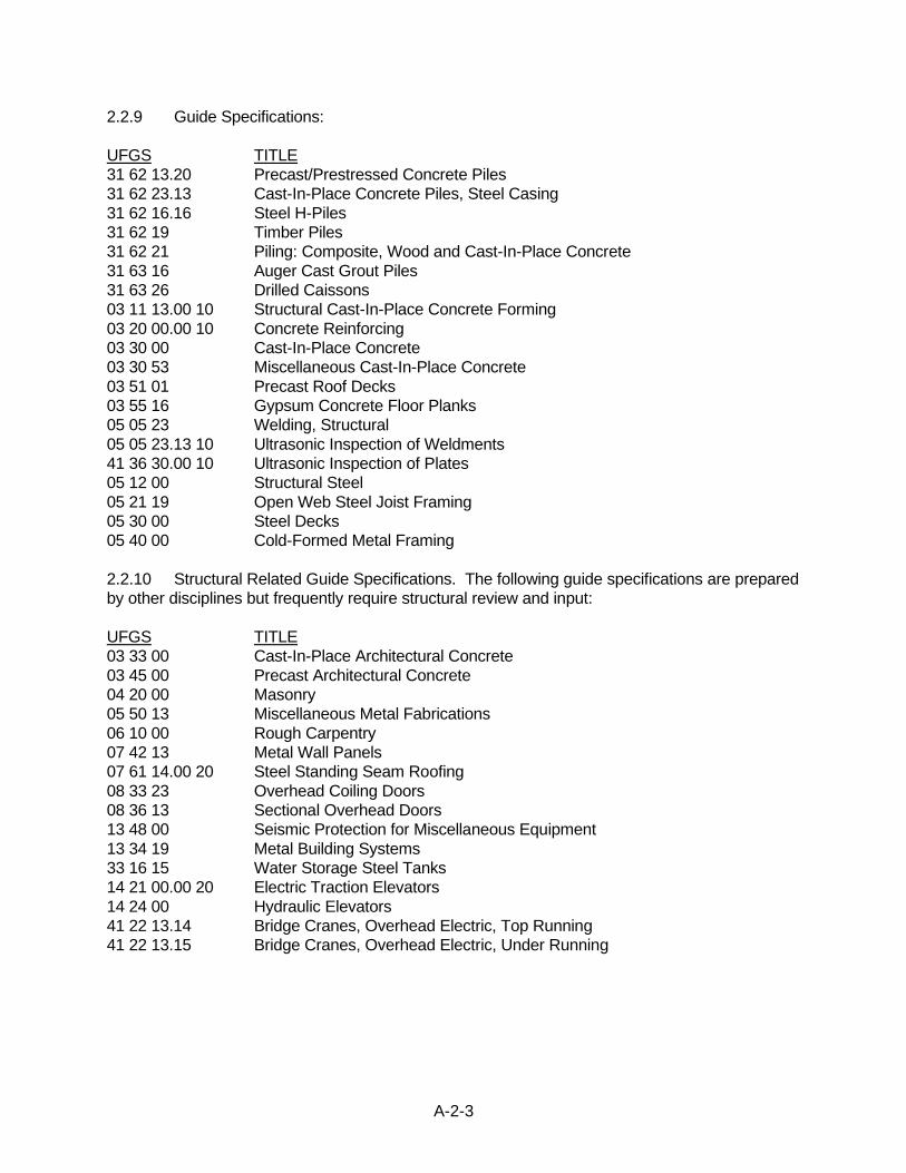
2.2.9 Guide Specifications:
UFGS TITLE
31 62 13.20 Precast/Prestressed Concrete Piles
31 62 23.13 Cast-In-Place Concrete Piles, Steel Casing
31 62 16.16 Steel H-Piles
31 62 19 Timber Piles
31 62 21 Piling: Composite, Wood and Cast-In-Place Concrete
31 63 16 Auger Cast Grout Piles
31 63 26 Drilled Caissons
03 11 13.00 10 Structural Cast-In-Place Concrete Forming
03 20 00.00 10 Concrete Reinforcing
03 30 00 Cast-In-Place Concrete
03 30 53 Miscellaneous Cast-In-Place Concrete
03 51 01 Precast Roof Decks
03 55 16 Gypsum Concrete Floor Planks
05 05 23 Welding, Structural
05 05 23.13 10 Ultrasonic Inspection of Weldments
41 36 30.00 10 Ultrasonic Inspection of Plates
05 12 00 Structural Steel
05 21 19 Open Web Steel Joist Framing
05 30 00 Steel Decks
05 40 00 Cold-Formed Metal Framing
2.2.10 Structural Related Guide Specifications. The following guide specifications are prepared
by other disciplines but frequently require structural review and input:
UFGS TITLE
03 33 00 Cast-In-Place Architectural Concrete
03 45 00 Precast Architectural Concrete
04 20 00 Masonry
05 50 13 Miscellaneous Metal Fabrications
06 10 00 Rough Carpentry
07 42 13 Metal Wall Panels
07 61 14.00 20 Steel Standing Seam Roofing
08 33 23 Overhead Coiling Doors
08 36 13 Sectional Overhead Doors
13 48 00 Seismic Protection for Miscellaneous Equipment
13 34 19 Metal Building Systems
33 16 15 Water Storage Steel Tanks
14 21 00.00 20 Electric Traction Elevators
14 24 00 Hydraulic Elevators
41 22 13.14 Bridge Cranes, Overhead Electric, Top Running
41 22 13.15 Bridge Cranes, Overhead Electric, Under Running

A-2-4
2.3 PRECONCEPT SUBMITTAL REQUIREMENTS No submittal requirements.
2.4 CODE 3 DESIGN REQUIREMENTS
2.4.1 Submittal. Submittal content and format shall be as described in UFC 3-710-01A, “Code 3
Design with Parametric Estimating.”
2.5 CONCEPT (35%) DESIGN SUBMITTAL REQUIREMENTS
The structural portion of the concept brochure must outline the proposed methods and materials
of design and construction for approval. An outline of the required brochure is shown in Exhibit
A-2-3. The design submittal shall include the following:
2.5.1 Structural Narrative:
2.5.1.1 General: Use present tense wording for all paragraphs. Provide a general description
of the scope of the project and all of the major structures. Give overall building dimensions and a
description of the principal features such as wall and roof construction. If the building is irregularly
shaped, explain where seismic joints will be placed to create regular shapes or provide a
statement that a dynamic analysis of the building will be performed (seismic joints are preferred
for most structures designed by the Savannah District).
2.5.1.2 Framing System: Provide a brief description of the gravity framing system and lateral
framing system chosen and the reasons why. Provide a brief description of how the lateral forces
will be transmitted into the foundations. If a Structural System Comparative Selection Analysis
(Section 2.5.3) is required then this paragraph should summarize the results of that analysis. The
analysis will appear later in the outline and shall justify the system selection.
2.5.1.3 Foundation: Give a brief description of the anticipated foundations based on similar
construction in the area.
2.5.1.4 Special Design Features: Briefly describe special features of the structural design
including, but not limited to, resistance to progressive collapse and blast resistant glazing.
2.5.1.5 Fire Resistance Statement: State the required fire resistance criteria for all portions of
the structural system and the proposed method of meeting these requirements.
2.5.1.6 Outstanding Structural Information: List the information that is needed from other
disciplines to complete the final structural design.
2.5.2 Concept Structural Design Analysis:
2.5.2.1 Load Assumptions: State the dead and live loads for which the facility is to be designed,
including roof loads, floor loads, and crane loads. Calculate the wind loads, lateral earth pressure
loads, seismic loads, etc., as applicable.
2.5.2.1.1 Dead Loads: tabulate all dead loads used and provide references for atypical materials.
2.5.2.1.2 Live Loads: tabulate all relevant live loads using the APPLICABLE PUBLICATIONS.
A-2-5
2.5.2.1.3 Wind Loads: Provide both main wind force resisting system (MWFRS) wind pressures
and components and cladding (C&C) wind pressures. Both positive and negative wind pressures
shall be included with the controlling pressures summarized in tabular form.
2.5.2.1.4 Seismic Loads: calculate the seismic loadings for the lateral load resisting system and
contrast them with the comparable wind loads. Detailed calculations for seismic loads on
diaphragm connections and other parts and portions are not required at this submittal level. Insert
sheet indicating that detailed calculations will be furnished for the preliminary (60%) design
package.
2.5.2.1.5 Crane Loads: provide crane loads if applicable.
2.5.2.1.6 Antiterrorism and Force Protection/Progressive Collapse Analysis: Provide a description
of any structural features required to meet ATFP requirements. A discussion of applicable
Progressive Collapse system and design approaches shall also be provided.
2.5.2.2 Material Strength & Allowable Stresses: tabulate the values to be used for material
strength (for LRFD design) and/or allowable stress (for ASD design) of the principal structural
materials such as concrete, structural steel, reinforcing steel, concrete masonry, and others.
2.5.2.3 Calculations: provide all calculations for wind loading, seismic loading, and snow
loading. No additional structural calculations are required to be completed at this submittal, but
any additional calculations that have been performed must be included in the submittal for review.
2.5.4 Concept Drawings. Furnish sufficient framing plans for foundations, floors, and roof, as
applicable, to indicate the preliminary layout of principal members including the locations of lateral
force resisting elements. Typical sections should be furnished through roof, floor, and foundation
indicating materials and type of construction proposed. These details may be shown on the
architectural drawings. Furnish a plan identifying the location of all seismic joints, if necessary.
Concept structural drawings must include general notes.
2.5.5 Outline Specifications: The Engineer shall review the list of guide specifications in this
section and shall list those sections he or she proposes to use at the end of his concept narrative.
2.5.6 Specific Instructions: Furnish a copy of the Specific Instructions (as prepared by SAS)
with the 35% submittal.
2.6 PRELIMINARY (OVER THE SHOULDER) (60%) SUBMITTAL REQUIREMENTS
2.6.1 Submittal: refer to SDDM Volume I Chapter 9.3.1 for submittal requirements.
2.7 PRELIMINARY (60%) DESIGN SUBMITTAL REQUIREMENTS
The preliminary design will represent approximately 60 percent of the total structural design effort.
2.7.1 Preliminary Design Analysis: The preliminary design analysis shall include all items in
the Concept design analysis and any revisions necessitated by comments from the Concept
review. The design analysis will be substantially complete for all the major structural features of
A-2-6
the primary structure and will include but not be limited to the following:
a. A brief structural narrative that provides the references, design loads, assumed material
strengths, and a brief description of the structure to include type of foundation, type of
framing, and method of resisting lateral loads.
b. A synopsis of special design criteria or technical requirements provided as a result of
site visits or correspondence with the Army Corps of Engineers Project Managers.
Copies of any letters or minutes of meetings which provide structural guidance not
otherwise contained in this manual should be included in this section of the design
analysis.
c. Complete calculation of seismic and wind loads for final design to include distribution of
these loads to the lateral load resisting elements.
d. Design calculations for roof and floor decks, beams, joists, girders, and columns as
applicable.
e. Design calculations for horizontal diaphragms and bracing to include shear transfer
connections.
f. Design calculations for exterior cladding (masonry, steel, precast concrete) for flexure,
shear, and overturning as appropriate.
g. Design calculations for shear walls, bracing, moment frames, and all other elements of
the lateral force resisting system and their connections.
h. Preliminary design calculations for antiterrorism and force protection systems and
progressive collapse analysis, as applicable. Complete design analysis and calculations
are required at final design.
i. Checking of the design at this stage will not be required. This submittal will not normally
include the design of lesser related structures such as utility vaults, pits, tanks, retaining
walls, tank hold down pads, etc. The design analysis of these structures is required at
final design.
2.7.2 Preliminary Drawings: This submittal will include the following as applicable:
a. Foundation plans, framing plans for each floor, and roof plans for the building. Plans
must indicate locations of bracing or other lateral force resisting elements. Grid lines on
center lines of columns shall be indicated on the plans for buildings framed with columns
and beams.
b. Elevations of braced bays must be included if braced frames are used for lateral force
resistance.
c. Layout of floor joints in slab on grade. Layout of construction joints, control joints,
expansion joints, and seismic joints in foundation, floor, and building framing.

A-2-7
d. Typical sections through foundations, floors, and roof framing for buildings.
e. Plans and sections of structures other than buildings.
f. Additional sections and details as required illustrating any special items or methods of
framing for which approval is sought.
g. General, foundation, and superstructure notes as shown in Exhibit A-2-2.
h. Future expansion information shall be noted on plans.
2.7.3 Preliminary Specifications: The concept submitted Unified Facilities Guide
Specifications (UFGS) list shall be updated to include any new specifications based on the
refined preliminary design. All specifications from the list shall be tentatively marked up, with
major edits, and submitted as part of the preliminary (60 percent) submittal. Specifications shall
comply with the requirements of Chapter A-11, SPECIFICATIONS. Specifications shall be
submitted with red-line edits indicating all deleted/modified text.
2.8 FINAL (100%) DESIGN SUBMITTAL REQUIREMENTS
2.8.1 Design Analysis: The final design analysis shall include all items in the Preliminary
design analysis and any revisions necessitated by comments from the Preliminary review.
Furnish complete checked calculations for all structural members.
2.8.2 Drawings: Furnish complete final plans and details of all structural elements. Prior to
this submittal, structural drawings shall be coordinated with all other design disciplines. Show on
drawings a complete set of general and special notes as shown in Exhibit A-2-2. The items listed
below will always be included on the final drawings if applicable:
a. Roof framing plan and details including details of any opening in the roof, elevations of
framing members, bearing on walls, etc.
b. Intermediate floor framing plans and stair details on multiple story structures.
c. Load diagrams of features to be contractor designed (i.e., light gauge truss or steel joist
load diagrams, bracing loads for connection design, etc).
d. All required schedules, including but not limited to beam schedules, column schedules,
slab schedules, wall schedules, foundation schedules, and anchor bolt and base plate
schedules.
e. Foundation plan including any notes relative to special foundation treatment required
and cross references to proper specification sections. Approximate locations and details
for stepped footings shall be provided.
f. Foundation sections and details.
g. Layout of expansion, construction, and contraction joints in floor slabs; horizontal and
vertical joints in foundation walls; joints in footings; and layout of control joints in
A-2-8
masonry walls.
h. Typical and special sections as required.
i. Details of expansion, construction, and contraction joints in concrete.
j. Layout and detail of exterior entrance pads and steps.
k. Details of any special items.
l. General and special notes as required except that the term "by others" shall not be
used.
2.8.3 Specifications: Submit a completed set of final specifications for review. Delegated
design items shall be completely coordinated and addressed in the specifications.
2.8.4 Quality Assurance: Final drawings and specifications shall be checked by the same
checker who checks the final design analysis. Structural drawings shall be coordinated with the
other disciplines and the specifications. Dimensions, schedules, sections, and details shall be
fully checked. Designers and checkers shall initial the pages of the design analysis and on the
drawings. Exhibit A-2-4 is a sample of the quality review checklist that will be used by the District
to review final design. The A-E is encouraged to use this, or a similar form, to review the final
checked design documents. Completed design review checklists shall be submitted as a part of
the submittal package.
2.9 CORRECTED FINAL DESIGN SUBMITTAL REQUIREMENTS
2.9.1 General: In the Corrected Final Design Submittal, the designer of record finalizes the
construction documents. This includes the incorporation of approved comments from the
previous design submittal reviews. The Corrected Final Design Submittal requirements shall be
the same as the Final Design Submittal requirements. Unless indicated otherwise in the project
Specific Instructions, this submittal will not be another review in ProjNet and is only for final
backcheck of all comments.
2.9.2 Design Analysis: Furnish final structural calculations, incorporating any and all changes
made during the process of review and redesign. Calculations will be checked and verified by an
engineer other than the original designer.
2.9.3 Drawings: Drawings will implement all comments from previous submittals. Verify that
all drawings are finalized and verify consistency between the plans and specifications.
2.10 ADDITIONS OR MODIFICATIONS TO EXISTING STRUCTURES
2.10.1 New Work: When new work is added to an existing structure or an existing structure is
modified, the Engineer will be responsible for determining the adequacy of the existing structure
for the addition or modification. This includes, but is not limited to, projects that place a sloped
roof over an existing flat roof.
A-2-9
2.10.2 Inspection Report: An inspection of the existing structure shall be performed for the
purpose of determining the condition and measurements of the areas affected by the new work.
The Concept Design shall include a narrative that outlines the results of this inspection to include
describing the layout and details of the existing structure, stating the calculated capability of the
structure to support the new loads, and describing the strengthening that will be required.
2.10.3 Seismic or Wind Upgrade: Seismic or wind upgrade of the existing structure to meet the
latest criteria will not be required unless specifically stated in the Structural Specific Instructions
(prepared by SAS) or required by applicable Code requirements.
2.11 SITE ADAPTS OF GOVERNMENT DESIGNS
2.11.1 Concept: The concept brochure shall be as previously described with the following
clarifications:
a. A selection analysis is not required.
b. Wind and seismic calculations shall be performed to verify that the controlling lateral
loads are higher or lower than the original design. Redesign of the structural features to
resist the higher loads will be required and the narrative will fully describe those items to
be strengthened.
2.11.2 Final Design: Final design shall consist of complete plans, specifications, and design
analysis. The specifications shall be the project specifications updated to include the latest
revisions to the Federal and Military guide specifications, design codes, and other criteria. The
design analysis shall include a narrative explanation of all changes to the original design to
accomplish the site adaptation with backup calculations.
2.12 GENERAL DESIGN REQUIREMENTS
2.12.1 Technical Requirements: Design will be accomplished in accordance with the basic
criteria provided herein and in the Specific Instructions (prepared by SAS) to the A-E.
2.12.2 Design Analysis: The design analysis shall be prepared in accordance with the general
requirements contained in Volume I of this manual and the requirements of this chapter.
2.12.2.1 Computer Analysis: Analysis and design using computer programs is encouraged. The
cover sheet of the structural calculations must identify what program(s) is (are) used. Listed
below are the commercially available programs currently used in the Structural Section. These or
other similar programs may be used except that use of a program not listed will necessitate the
submission of the following additional information for that program:
a. The name of the program.
b. A description of the program including discussion on how the program reaches solution.
This description must be sufficient to verify the validity of methods, assumptions,
theories, and formulas, but does not require source code documentation or other
information that would compromise the propriety rights.

A-2-10
c. A benchmark run validating the program that includes both a computer analysis and a
hand analysis of a typical or representative problem.
2.12.2.3 District Approved Computer Programs
a. RAM Structural System (Bentley)
b. STAAD.Pro (Bentley)
c. SAP2000 (Computers and Structures, Inc.)
d. ETABS (Computers and Structures, Inc.)
e. RISA 3-D (Risa Technologies)
f. GTSTRUDL (Georgia Tech CASE Center)
g. ENERCALC (ENERCALC, Inc.)
h. FrameWorks Plus (Intergraph)
2.13 REQUIREMENTS FOR DESIGN/BUILD RFP PACKAGES: To be furnished with
Specific Instructions (prepared by SAS) for the contract or delivery order and shall comply with
this chapter as modified by the Specific Instructions.
2.14 TECHNICAL DESIGN REQUIREMENTS
2.14.1 General Structural Requirements
2.14.1.1 Governing Code: All structures shall be designed in accordance with IBC as modified
by UFC 1-200-01. UFC 3-301-01, “Structural Engineering,” will be referred to henceforth in this
section because it is the document that UFC 1-200-01 delegates to for structural modifications
to the IBC.
2.14.1.2 Future Expansion: Where future expansion of buildings or facilities is planned,
provisions for the later expansion shall be shown on the drawings. Design assumptions for
expansion shall be noted on plans.
2.14.1.3 Structural Details: Structural details will be shown on the structural plans and not
intermixed with architectural plans and details.
2.14.1.4 Support of Nonstructural Items: In addition to performing the design of the structural
features, the structural engineer shall be responsible for ensuring that all mechanical and
electrical equipment is properly supported and that all architectural features are adequately
framed and connected in accordance with IBC provisions.
2.14.1.5 Components and Cladding (C&C) Diagram: The C&C wind zones for walls and roofs
will be shown on an isometric or 2D view of the building on one of the structural drawing sheets
and shall be accompanied by a table that identifies the C&C pressures for each zone.

A-2-11
Pressures and zones for arched and gable roof, overhangs, parapets, and any other unique
features shall be similarly shown.
2.14.2 Design Loads: Load assumptions shall be in accordance with IBC as modified by UFC
3-301-01.
2.14.2.1 Wind Load Criteria: Wind loads shall be in accordance with the IBC as modified by
UFC 3-301-01.
2.14.2.1.2 Velocity: The wind velocity will be in accordance with UFC 3-301-01. Wind
Exposure Category C shall be used unless Exposure D terrain requirements are present.
2.14.2.2 Seismic Load Criteria
2.14.2.2.1 Spectral Acceleration Values: The seismic spectral accelerations shall be in
accordance with UFC 3-301-01.
2.14.2.2.2 Bridges: Seismic criteria to be used for bridges shall be as set forth in the Standard
Specification for Highway Bridges, American Association of State Highway and Transportation
Officials (AASHTO).
2.14.2.2.3 All Other Structures: Seismic criteria to be used for structures other than bridges
shall be in accordance with IBC as modified by UFC 3-301-01.
2.14.2.3 Mechanical Loads: Roof systems over mechanical equipment rooms from which
equipment or piping will be supported and roofs of HVAC plants, pump stations, etc., shall be
designed for the equipment to be supported but not less than 60 PSF (2.9 kN/m2). Steel beams
are the preferred framing members over these areas since they are not as sensitive to hanger
attachment locations as are steel joists. Joists may be used over small mechanical rooms if
suspended ceiling loads will not produce hanger loads in excess of 50 pounds (25 Kg) per hanger.
Joists will not be used in HVAC plants, pump stations, or similar locations. Joists shall be
reinforced or designed for specific loads over 50 pounds.
2.14.2.4 Anti-terrorism/Force Protection (ATFP): ATFP systems must be included and shall
conform to UFC 4-010-01, “DoD Minimum Antiterrorism Standards for Buildings.” Additional
guidance may be found in UFC 4-023-03, “Design of Buildings to Resist Progressive Collapse.”
2.14.3 Structural Steel: Structural steel shall be designed in accordance with IBC as modified
by UFC 3-301-01.
2.14.4 Steel Joists: Steel joists shall be designed in accordance with IBC as modified by UFC
3-301-01. Joist depth and loading requirements shall be provided in the structural notes and
drawings. Joist camber requirements shall be coordinated with architectural roof finishes.
2.14.5 Concrete Design: Concrete shall be designed in accordance with IBC as modified by
UFC 3-301-01. 4000 psi (minimum) concrete shall be used for all structural concrete unless noted
otherwise.

A-2-12
2.14.6 Standing Seam Metal Roof (SSMR): Standing seam metal roofs shall be structural
SSMR with concealed clips. Architectural SSMR shall not be used. Concealed clips shall not
be fastened through rigid insulation to the structure below. If rigid insulation is provided
between metal roofing and deck below, sub-purlins shall be provided.
2.14.7 Concrete Masonry
2.14.7.1 Concrete Masonry Design: Concrete masonry shall be designed using approved wall
types in accordance with IBC as modified by UFC 3-301-01.
2.14.7.2 Drawings: At a minimum, the following items shall be included in the drawings to
properly describe the concrete masonry elements:
a. Wall elevations showing both horizontal and vertical reinforcing patterns for typical walls
and typical openings.
b. Details for bond beams.
c. Lintels for all openings in masonry walls, including windows, doors, and mechanical
work such as ducts.
d. A table of special inspections required for concrete masonry elements in accordance
with IBC as modified by UFC 3-301-01.
2.14.7.3 Efflorescence: Concrete masonry that has a tendency to display efflorescence shall not
be used in exterior applications.
2.14.7.4 Specification Coordination: Concrete masonry specifications shall be reviewed by the
structural engineer and the paragraphs of structural responsibility appropriately edited to include
retaining or deleting testing of mortar and prisms. Testing requirements shall be based on the
assumptions used for design and unnecessary tests will be deleted.
2.14.7.5 Mortar: Type N or S mortar will typically be used. One type of mortar is typically used for
all wall types on a project.
2.14.7.6 Interior Masonry Partitions: Interior partitions must be supported at the top of the wall by
adequate means such as angle braces to the roof system where they do not receive adequate
lateral support from cross walls or columns, or where the walls are broken by control joints such
that horizontal loads cannot be transferred longitudinally. Interior partitions which can be exposed
to wind forces due to the opening of large doors shall be designed as exterior walls. Minimum
seismic provisions apply to both interior partitions and to exterior walls. The design analysis shall
indicate where it was necessary to design interior partitions as exterior walls.
2.14.7.7 Openings in Walls: Where walls span horizontally between columns, the lintel over the
opening must be extended to the columns, and a bond beam below the opening must be
extended to the columns. Steel girts may be used for this purpose if necessary. Vertical
reinforcing in concrete filled cells will be used to take wind loads at large openings or to act as
pilasters where heavy lintels or beams bear on the walls.
A-2-13
2.14.7.8 Steel Beams Bearing on Masonry Walls: Steel beams which bear on masonry walls
should have slip plates and slotted holes at anchor bolts to provide for thermal movement.
2.14.7.9 Control Joints: Control joint spacing shall not be greater than recommended by the
masonry associations. Joints at the normal spacing must be coordinated with additional joints
required at the following locations:
a. At corners and intersections of exterior walls and partitions where roof framing would
impose horizontal loads to the top of the wall if the framing was subjected to a change of
length due to chance in temperature.
b. At all bond beam breaks.
c. At all large openings (10 ft or more in width or height).
d. At change in wall thickness or wall heights.
2.14.7.10 Brick Expansion Joints: Location of brick expansion joints is typically shown in plan
and detail on the architectural drawings. Their locations should be coordinated with the structural
engineer. The location of brick expansion joints and masonry control joints do not have to
coincide.
2.14.7.11 Bond Beams: Bond beams shall be placed at floor and roof level of all masonry
walls. Intermediate bond beam spacing between floor levels shall be in accordance with IBC, as
shall minimum and maximum reinforcing in bond beams. Reinforcement in bond beams shall be
continuous through control joints at all floor and roof levels.
2.14.7.12 Miscellaneous: the following miscellaneous criteria must be met for concrete
masonry:
a. Masonry must be set ¾ inch (20 mm) clear of all steel columns and ¾ inch (20 mm)
clear from the bottom flange of steel roof beams.
b. Lintels will be provided over all masonry openings, and slip joints will be used under
lintel bearings when a control joint is located within 2 feet (600 mm) of a masonry
opening.
c. If masonry is used within a rigid frame, the frame drift must be less than the allowable
deflection of the masonry wall as defined in IBC.
d. All lintels shall be designed in accordance with IBC.
e. For masonry walls used as stair and elevator shafts, all cells shall be grout filled solid.
2.14.8 Timber Trusses: Timber trusses and trussed joists shall be designed and detailed on
the structural drawings. Since connections for the truss members frequently employ proprietary
type plates, the connection design shall be specified to be accomplished by the joist/truss
fabricator and submitted for review by the Engineer of Record. The drawings prepared by the
Engineer shall include member sizes and stress diagrams which indicate the maximum member

A-2-14
forces for which the connections are to be designed. Support anchorage shall be specified and
detailed by the Engineer on the structural drawings. Under certain circumstances, and with the
prior approval of the Structural Section, the Engineer may delegate the design of the wood trusses
to a truss design fabricator. In this case, the truss details and framing plans prepared by the
Engineer shall number each truss, show its general configuration, and shall list the technical
requirements and loading. The truss design fabricator shall then prepare the complete design of
the truss and shall submit the design and design calculations to the Engineer for approval as part
of the shop drawings.
2.14.9 Foundation Design
2.14.9.1 Concrete: All concrete building foundations should be designed in accordance with IBC
as modified by UFC 3-301-01.
2.14.9.2 Foundation Type and Allowable Soil Bearing: The type of foundation, allowable
bearing value, and foundation depth will be furnished by the Savannah District Soils Section (EN-
GS) or the Design/Build Contractor’s Geotechnical Engineer.
2.14.9.3 Foundation Notes: Foundation notes similar to those shown in Exhibit A-2-2 shall be
included in the drawings.
2.14.10 Building Slab-on-Grade Design
2.14.10.1 Design: Slab-on-grade design shall be in accordance with UFC 3-301-01 and ACI
360R as modified by UFC 3-320-06A.
2.14.10.2 Forklift and Vehicular Loads: Slabs-on-grade subject to forklift and/or vehicular
loads shall have the loading described in the general notes. For such slabs-on-grade, the
minimum concrete strength shall be 4,000 psi even if it is reinforced in order to achieve a durable
wearing surface. Use a floor hardener if applicable.
2.14.10.3 Slab-on-Grade Criteria
a. Floor joints (contraction, construction, expansion) must always be shown on the
structural drawings.
b. Use a vapor barrier under all slabs on grade for buildings sensitive to moisture.
c. Use 4 inches (100 mm) gravel capillary water barrier under all building slabs on grade
when directed by the soil report.
d. Use #30 felt between floor slabs on grade and foundation walls, beams, and piers.
e. Slabs on grade shall not bear on grade beams, walls, or piers except where provision is
made to reinforce the slab to prevent cracking should soil settlement beneath the slab
occur.
f. Refer to Exhibit A-2-2 for sample general notes for slab-on-grade.

A-2-15
g. Rebar or welded wire fabric (provided in sheets, not rolls) may be used. Support
spacing of welded wire fabric shall be specified on the drawings or in the specifications.
Where columns occur, floor control joints should be placed on column centerlines.
h. Slabs on grade with perimeter felt joints and with floor drains, such as in mechanical
rooms, will have a rubber joint sealant on top of the felt joint.
i. In wash rack areas, joints should be minimized by use of more reinforcement. The joint
between slab on grade and foundation should have a rubber joint sealant.
j. Topping over concrete slabs must be avoided where possible. Where it is not possible,
it should be a minimum of 2 inches (50 mm) thick and reinforced with 0.1 percent
reinforcement in bars or mesh in flat sheets. Fiber reinforcement may also be provided
in accordance with manufacturer’s instructions.
k. Use of expansive cement and minimization of joints may be considered where
economical. Where used, it should be at the Contractor's option.
2.14.11 Building Frame Design Considerations
2.14.11.1 Load-Bearing Walls Versus Frame Type Buildings: Some type of building frame
usually is required where a building length or length between shear walls is more than three times
its width, where long clear spans are required [30 m (100 feet) or more], or where the building
one-story height is in excess of 5.5 m (18 feet). Provide expansion joints through building frame
at 300-foot (90 m) o.c., maximum. A comparative cost estimate should accompany concept plans
to show the basis for frame selection.
2.14.11.2 Concrete Building Frames: Use Grade 60 steel reinforcing bars. Light-weight
concrete may be used for floor framing but not for columns; 5000 psi (35 MPa) concrete may be
used where economical; 4000 psi (27.5 MPa) concrete is normally used for pan joist floors. Types
of concrete floors which have proved economical are flat slab, waffle slab, pan joist and precast
concrete joists. Design dead loads should include the additional concrete topping required due to
precast joist camber. Reinforcing in pan joist slabs should be bars or mesh in flat sheets.
Minimum reinforcing should be 0.18 percent in each direction for mesh, or 0.2 percent for bars in
a direction at right angles to joists, but bar spacing must not be greater than 3t. Bars must also be
tied with cross bars at 18-inch (450 mm) o.c. maximum. Thickness of pan joist slab shall be 2-1/2
inch (65 mm) minimum.
2.14.11.3 Steel Building Frames: In general, shop welded, field bolted construction should be
used, except that hanger straps supporting cranes or monorails shall be high strength bolted.
High strength bolts for field connections may be used where economy or ease of construction
dictates. ASTM A992 steel should be used for wide flange shapes. Bar joists should be K series
as defined by the Steel Joist Institute. Long-span joists may be used where required by span and
load. Specify standard joists where possible. The attached structural steel framing notes (Exhibit
A-2-2) should be used where applicable. Steel columns must be clear of masonry walls. Where
steel members are anchored to masonry walls to provide support, care must be used to provide
slotted holes to allow the wall to move relative to the steel. Specify a nondestructive test on 100
percent of all butt-welded beam or column connections.

A-2-16
Where steel beams are used to support the metal deck system, the spacing can be increased up
to about 2.75 m (9 feet) o.c. provided the floor slab is thickened and the metal deck system is
properly designed. A vibration analysis of these type floor systems is required.
2.14.11.4 Metal buildings (MB): MB systems may be used where indicated by the directive or
as otherwise approved by the Structural Section. If negotiations assumed a custom designed
building and a metal building is later approved for use, then the original design contract is subject
to renegotiation for the reduction in architectural and structural effort. The attached notes in
Exhibit A-2-2 relating to this type building should be used. The Contractor shall design the
building foundation based on the reactions provided by the metal building system engineer.
Metal buildings shall be procured using Guide Specification UFGS 13 34 19, METAL BUILDING
SYSTEMS. The structural drawings shall include a foundation plan which indicates an estimate of
the foundation requirements for a typical pre-engineered building that will meet the project
requirements. The foundation plan shall be consistent with the requirements of the Government-
furnished foundation report. This plan will be supported by notes that clearly define any additional
requirements required by the COE.
2.14.11.5 Basements: Usually, basement floors will be slab-on-grade construction separated
from basement walls by #30 felt. Basement walls should have membrane waterproofing on the
outside and under the slab with a continuous perforated tile drain around the basement where
required by the soils report.
2.14.11.6 Suspended ceilings on the exterior of building over entrances: These ceilings must
be designed for wind loads. Structural steel angles or light gauge framing instead of wire hangers
are normally used here since uplift can be a problem. Ceilings (excluding acoustic ceiling tile
systems unless specifically engineered accordingly) may be considered as support for metal stud
partitions.
2.14.12 Seismic Design Considerations
2.14.12.1 The basic seismic technical requirements shall be in accordance with IBC as
modified by UFC 1-200-01.
2.14.12.2 The following is a list of exceptions and clarifications to the references:
a. Avoid use of tie rods for bracing. Use structural rolled shapes.
b. Precast concrete, prestressed concrete, and flat slabs do not qualify as components of
ductile moment resisting elements.
c. Metal Buildings. Panels thinner than 22 gauge (0.75 mm) with self-tapping screws are not
permitted for diaphragms or shear walls. All roof or wall systems using siding or roofing as a
diaphragm must be tested for in-plane loading for diaphragm or shear wall effects. Test
reports and recommendations must be submitted for evaluation and approval. The steel
deck system must have the ability to transmit diaphragm loads and is dependent upon the
deck strength, stiffness, panel configuration, fastening method and condition of installation.
Since approval of tests on these systems is tedious and time consuming, cross-bracing, rigid
frame wind bents, or wind columns are the preferred system. Specifications for metal
A-2-17
buildings must require submission of load tests on metal panel walls and roof where used as
a diaphragm.
d. The allowable drift of walls, in all cases, must be considered before selecting the type of
diaphragm. All story drifts must be checked so that they will be compatible with the
diaphragm deflection (especially for brittle walls).
e. The criteria for separation of buildings will apply to seismic joints for parts of buildings.
Portions of a building with differing dynamic responses will be separated from each other
with seismic joints. Analysis of setbacks in plan and/or elevation per IBC shall be required
to preclude use of seismic joints.
f. Connection of diaphragm to vertical-load-carrying precast elements is necessary to transmit
the lateral force generated from the weights of the frame and other masses attached thereto
to the diaphragm. Also, the response of the supporting element when subjected to
earthquake motion must be in resonance with the diaphragm. Therefore, positive
anchorage, such as mechanical fasteners, dowels, or welding as appropriate must be
provided.
g. Prestressed, precast concrete frames are not permitted to be used as semiductile frames.
The capability or performance of semiductile moment resisting frames of prestressed,
precast construction is questioned. Based on our knowledge, its use has not been accepted
by codes. Therefore, we cannot allow its use without any specific information or design data
to confirm its performance and structural adequacy.
h. Buildings with basements or buried structures may be required to be analyzed for the effect
of dynamic soil loadings.
i. Design analysis shall include the design of collector elements for over-strength factor as
applicable by code.
2.14.12.3 Seismic vs. Wind: When comparing wind and seismic calculations the general
perception that wind or seismic governs totally in a particular direction is not valid. Even though
wind or seismic governs a particular direction based on the overall magnitude of load in that
direction does not mean that the other is ruled out when considering the design of individual
elements of the building that are affected by lateral load in that direction. As will be demonstrated
below, wind and seismic calculations have, for different systems and elements, different factors
applied to the loads on those elements. This greatly complicates a "controlling load
determination," and mandates that this determination not be made on the building as a whole, but
that each element of the building must be considered separately, (i.e., parts and portions of a
building are to be designed individually for the highest load on them). Both seismic and wind
loads should be taken to individual elements and then only after placing the proper factors to the
loads should the highest load be selected.

A-2-18
2.14.13 Miscellaneous Structures
2.14.13.1 Manholes, Pullboxes, Surface Inlets : A minimum 3000 psi (20 Mpa) compressive
strength concrete will be used. Verify location of water table with Soils Section (EN-GS) and
check for uplift. Standard precast concrete structures are acceptable and desired where more
economical. H-15 wheel loads will be used except for structures in pavement which will be
designed for the wheel load for which the pavement was designed.
2.14.13.2 Headwalls and Box Culverts: Minimum 3000 psi (20 Mpa) compressive strength
concrete should be used.
2.14.13.3 Transformer Pads, Condenser Pads, and Generator Pads: Concrete should be
minimum 3000 psi (20 Mpa) compressive strength.
2.14.13.4 Retaining Walls, Basement Walls: Lateral earth loads on structures should be based
on p = whK; where p = lateral pressure, w = wet unit weight of earth [120 psf (20 kN/m3)
minimum, may be higher in some areas], h = depth of structure, and K is a coefficient (use 0.5 for
retaining walls, 0.7 for basement walls and box culverts), and verify with Soils Section (EN-GS).
Surcharge loads should be included where applicable. Investigation should also be made using
100 percent hydrostatic pressure (where applicable) at one-third overstress (50 percent where
drains are used). The working stress method of design is preferred with actual loads on the wall.
2.14.13.5 Monorail Design: Monorail beams shall be designed for maximum bending stress of:
f = 3,000,000 but not greater than 10,000 psi (69 Mpa).
1d/bt
based on rated capacity of the hoist plus 25 percent impact and full dead loads for vertical loads,
and 20 percent of rated capacity + 25 percent impact for horizontal loads. Deflections should be
limited to L/800.
Beams shall also be checked for a maximum overload of 2.75 times the rated hoist capacity at 75
percent of the yield stress. An "I" beam, with channel on top, (T) section should be used for all but
very short spans. The hangers and system supporting the monorail beam should be designed for
the same loads but at normal stresses. Knee braces should be provided where applicable. Field
connections should be A325 bolted connections.
2.14.13.6 Traveling Crane Runway Girders: Runway girders will normally be designed by the
crane vendor and will be provided based on performance specifications. The following guidelines
should be included in these specifications.
2.14.13.6.1 Continuous girders should not be used where significant unequal foundation
settlement is likely to occur. Where foundations are other than shale or hard rock, check
anticipated differential settlement so that the difference is limited to 0.003 L between adjacent
supports. (Simply supported girders are not ordinarily affected by differential foundation
movements.)
2.14.13.6.2 Limit live load deflection at midspan to "L"/1,000.
A-2-19
2.14.13.6.3 For continuous girders, limit ratio of length of adjacent spans to 2:1.
2.14.13.6.4 Connect ends of simply supported girders in such a manner that will allow the ends
to rotate under vertical loading.
2.14.13.6.5 Proprietary hanging systems by the successful bidder are preferred over direct
bolted connections.
2.14.13.7 Precast Concrete Panels: Precast concrete panels used as non-load bearing
construction should have connections such that thermal expansion or contraction may occur
without damage to the panels. These connections should at least allow movement at one end of
the panel. These connections could be in the form of studs welded to embedded steel plates and
anchored into an angle with slotted holes in the direction of expected movement. Also, when the
panels bear on other members such as steel or concrete, the expansion end of the panels should
bear on neoprene pads, steel or some such material that will minimize the frictional resistance to
movement. The precast concrete of the shearing areas should be reinforced additionally
horizontally and vertically to minimize cracking of these bearing areas. Reference is made to PCI
Manual for Structural Design of Architectural Precast Concrete. Seismic connections should be in
accordance with IBC.
2.14.14 Fire Walls: shall be designed in accordance with current IBC provisions.
A-2-20
CHAPTER A-2
STRUCTURAL
APPENDIX: EXHIBITS
A-2-1 Wind Velocities and Seismic Spectral Accelerations at Local Installations
A-2-2 General Notes (For Information Only)
A-2-3 Concept (35%) Design Brochure Outline
A-2-4 Structural Section Quality Control Checklist for Review of A-E Final Design

EXHIBIT A-2-2
Page 1 of 8
WIND VELOCITIES AND SEISMIC SPECTRAL ACCELERATIONS AT LOCAL
INSTALLATIONS
Wind and Seismic criteria for specific locations shall be identified using the structural load data
tool hosted on the Whole Building Design Guide website at https://www.wbdg.org/additional-resources/tools/ufcsldt.
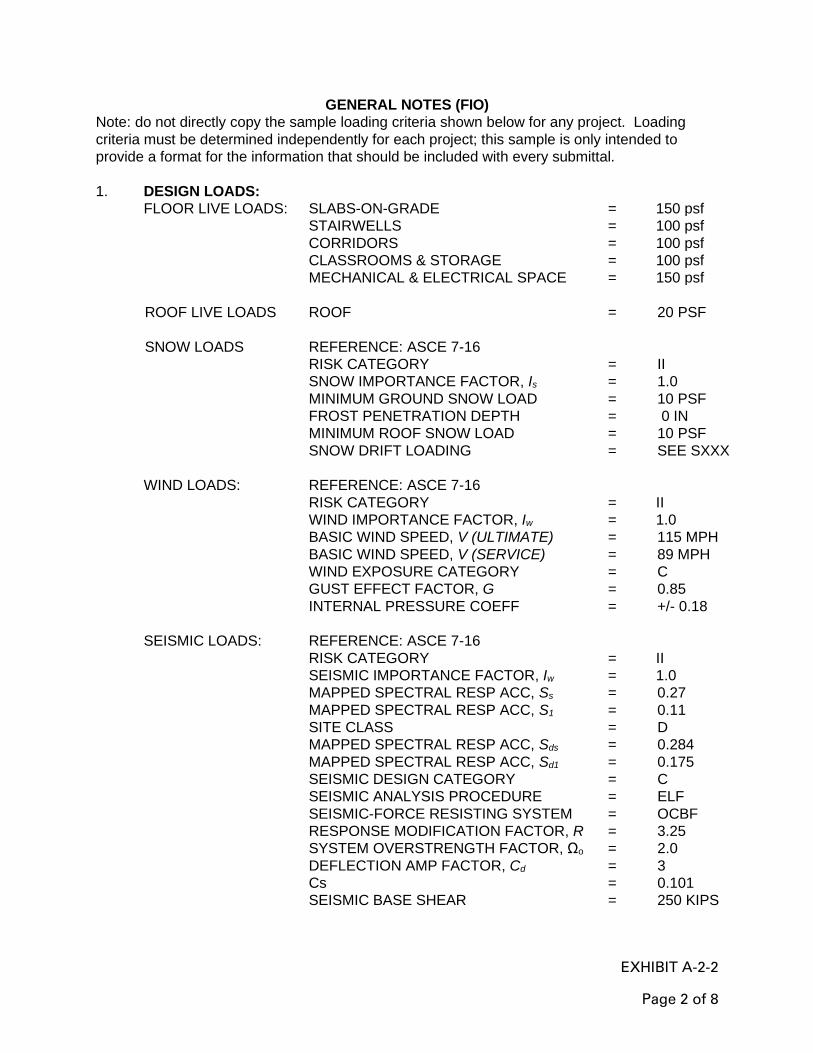
EXHIBIT A-2-2
Page 2 of 8
GENERAL NOTES (FIO)
Note: do not directly copy the sample loading criteria shown below for any project. Loading
criteria must be determined independently for each project; this sample is only intended to
provide a format for the information that should be included with every submittal.
1. DESIGN LOADS:
FLOOR LIVE LOADS: SLABS-ON-GRADE = 150 psf
STAIRWELLS = 100 psf
CORRIDORS = 100 psf
CLASSROOMS & STORAGE = 100 psf
MECHANICAL & ELECTRICAL SPACE = 150 psf
ROOF LIVE LOADS ROOF = 20 PSF
SNOW LOADS REFERENCE: ASCE 7-16
RISK CATEGORY = II
SNOW IMPORTANCE FACTOR, Is = 1.0
MINIMUM GROUND SNOW LOAD = 10 PSF
FROST PENETRATION DEPTH = 0 IN
MINIMUM ROOF SNOW LOAD = 10 PSF
SNOW DRIFT LOADING = SEE SXXX
WIND LOADS: REFERENCE: ASCE 7-16
RISK CATEGORY = II
WIND IMPORTANCE FACTOR, Iw = 1.0
BASIC WIND SPEED, V (ULTIMATE) = 115 MPH
BASIC WIND SPEED, V (SERVICE) = 89 MPH
WIND EXPOSURE CATEGORY = C
GUST EFFECT FACTOR, G = 0.85
INTERNAL PRESSURE COEFF = +/- 0.18
SEISMIC LOADS: REFERENCE: ASCE 7-16
RISK CATEGORY = II
SEISMIC IMPORTANCE FACTOR, Iw = 1.0
MAPPED SPECTRAL RESP ACC, Ss = 0.27
MAPPED SPECTRAL RESP ACC, S1 = 0.11
SITE CLASS = D
MAPPED SPECTRAL RESP ACC, Sds
MAPPED SPECTRAL RESP ACC, Sd1
SEISMIC DESIGN CATEGORY
SEISMIC ANALYSIS PROCEDURE
SEISMIC-FORCE RESISTING SYSTEM
RESPONSE MODIFICATION FACTOR, R
SYSTEM OVERSTRENGTH FACTOR, Ωo
DEFLECTION AMP FACTOR, Cd
Cs
= 0.284
= 0.175
= C
= ELF
= OCBF
= 3.25
= 2.0
= 3
= 0.101
SEISMIC BASE SHEAR = 250 KIPS

EXHIBIT A-2-2
Page 3 of 8
ATFP CRITERIA: REFERENCE: UFC 4-010-01
NEW BUILDING LOCATION
BUILDING CATEGORY
DESIGN LEVEL OF PROTECTION
PROGRESSIVE COLLAPSE APPLIES
WITHIN A
CONTROLLED
PERIMETER
PRIMARY
GATHERING
BUILDING
LOW (LLOP)
YES (>3 STORIES)
1. WHERE A SECTION OR DETAIL IS SHOWN FOR ONE CONDITION, IT SHALL
APPLY TO ALL LIKE AND SIMILAR CONDITIONS.
2. THE CONTRACTOR SHALL BE RESPONSIBLE FOR THE DESIGN AND DETAIL OF
SIMPLE (SHEAR ONLY) CONNECTIONS NOT SHOWN ON THE DRAWINGS.
3. NO CORE DRILLING WILL BE PERMITTED IN THE FOUNDATION WALLS OR IN
THE ELEVATED SLABS. REFER TO THE MECHANICAL, ELECTRICAL, AND
PLUMBING DRAWINGS TO LOCATE PENETRATIONS. THE PENETRATION
LOCATIONS MUST BE SHOWN IN THE SHOP DRAWING SUBMITTALS.
CONCRETE MASONRY NOTES (FIO)
1. ALL CONCRETE MASONRY WORK SHALL CONFORM TO ACI 530.
2. ALL CMU SHALL BE TWO-CELL TYPE UNITS EXCEPT LINTELS WHICH SHALL BE
U-SHAPED UNITS.
3. BOND BEAM UNITS MAY BE U-SHAPED OR TWO-CELL TYPE.
4. ALL CMU SHALL CONFORM TO ASTM C-90 OR EQUIVALENT METRIC STANDARD.
5. ALL CELLS CONTAINING REINFORCING SHALL BE FULL GROUTED.
6. USE TYPE S MORTAR WITH A MINIMUM COMPRESSIVE STRENGTH OF 1800 psi
AT 28 DAYS.
7. VERTICAL CELLS TO BE FILLED SHALL HAVE VERTICAL ALIGNMENT SUFFICIENT
TO MAINTAIN A CLEAR UNOBSTRUCTED CONTINUOUS VERTICAL CELL NOT
LESS THAN 50 X 75mm PLAN DIMENSIONS.
8. ALL MASONRY BOND BEAMS, LINTELS, AND VERTICALLY GROUTED CELLS
SHALL BE FILLED SOLIDLY WITH 2500 psi GROUT.
9. BOND BEAMS AT CMU WALLS THAT ARE PERPENDICULAR TO EACH OTHER
SHALL MEET AT THE SAME ELEVATION AND THE REINFORCING SHALL BE
LAPPED AS REQUIRED.
10. ALL CONCRETE MASONRY UNITS SHALL HAVE A GROSS SPECIFIED
COMPRESSIVE STRENGTH OF 2000 psi AT 28 DAYS.
11. DOWELS FROM THE ATTIC SLAB SHALL BE PROVIDED. THE SPACING AND SIZE
OF THE DOWELS SHALL MATCH THE VERTICAL REINFORCING BARS.
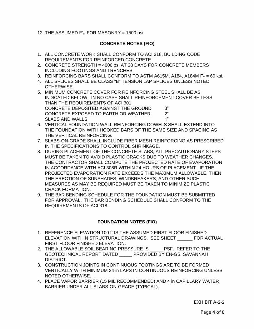
EXHIBIT A-2-2
Page 4 of 8
12. THE ASSUMED F’m FOR MASONRY = 1500 psi.
CONCRETE NOTES (FIO)
1. ALL CONCRETE WORK SHALL CONFORM TO ACI 318, BUILDING CODE
REQUIREMENTS FOR REINFORCED CONCRETE.
2. CONCRETE STRENGTH = 4000 psi AT 28 DAYS FOR CONCRETE MEMBERS
INCLUDING FOOTINGS AND TRENCHES.
3. REINFORCING BARS SHALL CONFORM TO ASTM A615M, A184, A184M FY = 60 ksi.
4. ALL SPLICES SHALL BE CLASS "B" TENSION LAP SPLICES UNLESS NOTED
OTHERWISE.
5. MINIMUM CONCRETE COVER FOR REINFORCING STEEL SHALL BE AS
INDICATED BELOW. IN NO CASE SHALL REINFORCEMENT COVER BE LESS
THAN THE REQUIREMENTS OF ACI 301.
CONCRETE DEPOSITED AGAINST THE GROUND 3”
CONCRETE EXPOSED TO EARTH OR WEATHER 2”
SLABS AND WALLS 1”
6. VERTICAL FOUNDATION WALL REINFORCING DOWELS SHALL EXTEND INTO
THE FOUNDATION WITH HOOKED BARS OF THE SAME SIZE AND SPACING AS
THE VERTICAL REINFORCING.
7. SLABS-ON-GRADE SHALL INCLUDE FIBER MESH REINFORCING AS PRESCRIBED
IN THE SPECIFICATIONS TO CONTROL SHRINKAGE.
8. DURING PLACEMENT OF THE CONCRETE SLABS, ALL PRECAUTIONARY STEPS
MUST BE TAKEN TO AVOID PLASTIC CRACKS DUE TO WEATHER CHANGES.
THE CONTRACTOR SHALL COMPUTE THE PROJECTED RATE OF EVAPORATION
IN ACCORDANCE WITH ACI 308R WITHIN 24 HOURS OF PLACEMENT. IF THE
PROJECTED EVAPORATION RATE EXCEEDS THE MAXIMUM ALLOWABLE, THEN
THE ERECTION OF SUNSHADES, WINDBREAKERS, AND OTHER SUCH
MEASURES AS MAY BE REQUIRED MUST BE TAKEN TO MINIMIZE PLASTIC
CRACK FORMATION.
9. THE BAR BENDING SCHEDULE FOR THE FOUNDATION MUST BE SUBMITTED
FOR APPROVAL. THE BAR BENDING SCHEDULE SHALL CONFORM TO THE
REQUIREMENTS OF ACI 318.
FOUNDATION NOTES (FIO)
1. REFERENCE ELEVATION 100 ft IS THE ASSUMED FIRST FLOOR FINISHED
ELEVATION WITHIN STRUCTURAL DRAWINGS. SEE SHEET ______ FOR ACTUAL
FIRST FLOOR FINISHED ELEVATION.
2. THE ALLOWABLE SOIL BEARING PRESSURE IS _____ PSF. REFER TO THE
GEOTECHNICAL REPORT DATED _____ PROVIDED BY EN-GS, SAVANNAH
DISTRICT.
3. CONSTRUCTION JOINTS IN CONTINUOUS FOOTINGS ARE TO BE FORMED
VERTICALLY WITH MINIMUM 24 in LAPS IN CONTINUOUS REINFORCING UNLESS
NOTED OTHERWISE.
4. PLACE VAPOR BARRIER (15 MIL RECOMMENDED) AND 4 in CAPILLARY WATER
BARRIER UNDER ALL SLABS-ON-GRADE (TYPICAL).
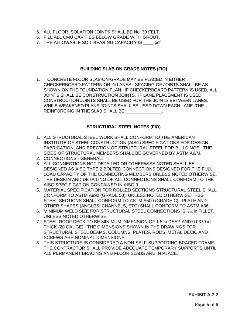
EXHIBIT A-2-2
Page 5 of 8
5. ALL FLOOR ISOLATION JOINTS SHALL BE No. 30 FELT.
6. FILL ALL CMU CAVITIES BELOW GRADE WITH GROUT.
7. THE ALLOWABLE SOIL BEARING CAPACITY IS ____ psf.
BUILDING SLAB ON GRADE NOTES (FIO)
1. CONCRETE FLOOR SLAB-ON-GRADE MAY BE PLACED IN EITHER
CHECKERBOARD PATTERN OR IN LANES. SPACING OF JOINTS SHALL BE AS
SHOWN ON THE FOUNDATION PLAN. IF CHECKERBOARD PATTERN IS USED, ALL
JOINTS SHALL BE CONSTRUCTION JOINTS. IF LANE PLACEMENT IS USED,
CONSTRUCTION JOINTS SHALL BE USED FOR THE JOINTS BETWEEN LANES,
WHILE WEAKENED PLANE JOINTS SHALL BE USED DOWN EACH LANE. THE
REINFORCING IN THE SLAB SHALL BE _______________.
STRUCTURAL STEEL NOTES (FIO)
1. ALL STRUCTURAL STEEL WORK SHALL CONFORM TO THE AMERICAN
INSTITUTE OF STEEL CONSTRUCTION (AISC) SPECIFICATIONS FOR DESIGN,
FABRICATION, AND ERECTION OF STRUCTURAL STEEL FOR BUILDINGS. THE
SIZES OF STRUCTURAL MEMBERS SHALL BE GOVERNED BY ASTM A6/M.
2. CONNECTIONS - GENERAL:
3. ALL CONNECTIONS NOT DETAILED OR OTHERWISE NOTED SHALL BE
DESIGNED AS AISC TYPE 2 BOLTED CONNECTIONS DESIGNED FOR THE FULL
LOAD CAPACITY OF THE CONNECTING MEMBERS UNLESS NOTED OTHERWISE.
4. THE DESIGN AND DETAILING OF ALL CONNECTIONS SHALL CONFORM TO THE
AISC SPECIFICATION CONTAINED IN AISC-9.
5. MATERIAL SPECIFICATION FOR ROLLED SECTIONS STRUCTURAL STEEL SHALL
CONFORM TO ASTM A992 (GRADE 50), UNLESS NOTED OTHERWISE. HSS
STEEL SECTIONS SHALL CONFORM TO ASTM A500 (GRADE C). PLATE AND
OTHER SHAPES (ANGLES, CHANNELS, ETC) SHALL CONFORM TO ASTM A36.
6. MINIMUM WELD SIZE FOR STRUCTURAL STEEL CONNECTIONS IS 3/16 in FILLET,
UNLESS NOTED OTHERWISE.
7. STEEL ROOF DECK TO BE MINIMUM DIMENSION OF 1.5 in DEEP AND 0.0379 in
THICK (20 GAUGE). THE DIMENSIONS SHOWN IN THE DRAWINGS FOR
STRUCTURAL STEEL BEAMS, COLUMNS, PLATES, RODS, METAL DECK, AND
SCREWS ARE NOMINAL DIMENSIONS.
8. THIS STRUCTURE IS CONSIDERED A NON-SELF-SUPPORTING BRACED FRAME.
THE CONTRACTOR SHALL PROVIDE ADEQUATE TEMPORARY SUPPORTS UNTIL
ALL PERMANENT BRACING AND FLOOR SLABS ARE IN PLACE.
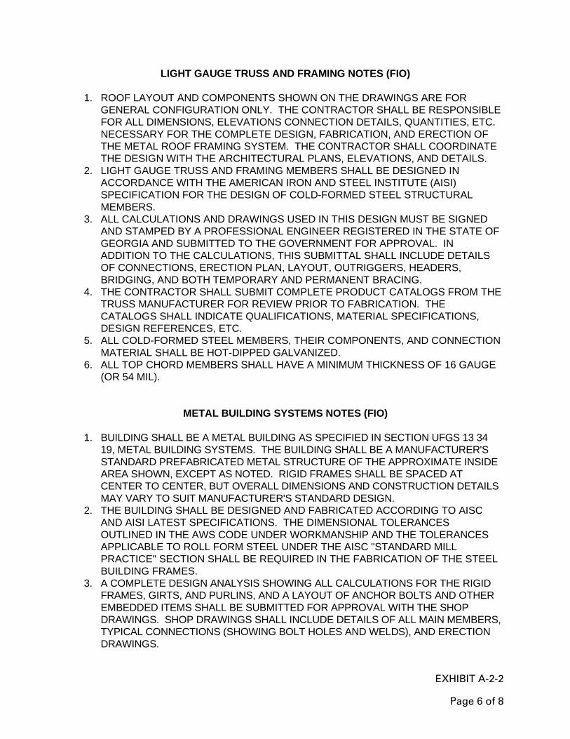
EXHIBIT A-2-2
Page 6 of 8
LIGHT GAUGE TRUSS AND FRAMING NOTES (FIO)
1. ROOF LAYOUT AND COMPONENTS SHOWN ON THE DRAWINGS ARE FOR
GENERAL CONFIGURATION ONLY. THE CONTRACTOR SHALL BE RESPONSIBLE
FOR ALL DIMENSIONS, ELEVATIONS CONNECTION DETAILS, QUANTITIES, ETC.
NECESSARY FOR THE COMPLETE DESIGN, FABRICATION, AND ERECTION OF
THE METAL ROOF FRAMING SYSTEM. THE CONTRACTOR SHALL COORDINATE
THE DESIGN WITH THE ARCHITECTURAL PLANS, ELEVATIONS, AND DETAILS.
2. LIGHT GAUGE TRUSS AND FRAMING MEMBERS SHALL BE DESIGNED IN
ACCORDANCE WITH THE AMERICAN IRON AND STEEL INSTITUTE (AISI)
SPECIFICATION FOR THE DESIGN OF COLD-FORMED STEEL STRUCTURAL
MEMBERS.
3. ALL CALCULATIONS AND DRAWINGS USED IN THIS DESIGN MUST BE SIGNED
AND STAMPED BY A PROFESSIONAL ENGINEER REGISTERED IN THE STATE OF
GEORGIA AND SUBMITTED TO THE GOVERNMENT FOR APPROVAL. IN
ADDITION TO THE CALCULATIONS, THIS SUBMITTAL SHALL INCLUDE DETAILS
OF CONNECTIONS, ERECTION PLAN, LAYOUT, OUTRIGGERS, HEADERS,
BRIDGING, AND BOTH TEMPORARY AND PERMANENT BRACING.
4. THE CONTRACTOR SHALL SUBMIT COMPLETE PRODUCT CATALOGS FROM THE
TRUSS MANUFACTURER FOR REVIEW PRIOR TO FABRICATION. THE
CATALOGS SHALL INDICATE QUALIFICATIONS, MATERIAL SPECIFICATIONS,
DESIGN REFERENCES, ETC.
5. ALL COLD-FORMED STEEL MEMBERS, THEIR COMPONENTS, AND CONNECTION
MATERIAL SHALL BE HOT-DIPPED GALVANIZED.
6. ALL TOP CHORD MEMBERS SHALL HAVE A MINIMUM THICKNESS OF 16 GAUGE
(OR 54 MIL).
METAL BUILDING SYSTEMS NOTES (FIO)
1. BUILDING SHALL BE A METAL BUILDING AS SPECIFIED IN SECTION UFGS 13 34
19, METAL BUILDING SYSTEMS. THE BUILDING SHALL BE A MANUFACTURER'S
STANDARD PREFABRICATED METAL STRUCTURE OF THE APPROXIMATE INSIDE
AREA SHOWN, EXCEPT AS NOTED. RIGID FRAMES SHALL BE SPACED AT
CENTER TO CENTER, BUT OVERALL DIMENSIONS AND CONSTRUCTION DETAILS
MAY VARY TO SUIT MANUFACTURER'S STANDARD DESIGN.
2. THE BUILDING SHALL BE DESIGNED AND FABRICATED ACCORDING TO AISC
AND AISI LATEST SPECIFICATIONS. THE DIMENSIONAL TOLERANCES
OUTLINED IN THE AWS CODE UNDER WORKMANSHIP AND THE TOLERANCES
APPLICABLE TO ROLL FORM STEEL UNDER THE AISC "STANDARD MILL
PRACTICE" SECTION SHALL BE REQUIRED IN THE FABRICATION OF THE STEEL
BUILDING FRAMES.
3. A COMPLETE DESIGN ANALYSIS SHOWING ALL CALCULATIONS FOR THE RIGID
FRAMES, GIRTS, AND PURLINS, AND A LAYOUT OF ANCHOR BOLTS AND OTHER
EMBEDDED ITEMS SHALL BE SUBMITTED FOR APPROVAL WITH THE SHOP
DRAWINGS. SHOP DRAWINGS SHALL INCLUDE DETAILS OF ALL MAIN MEMBERS,
TYPICAL CONNECTIONS (SHOWING BOLT HOLES AND WELDS), AND ERECTION
DRAWINGS.

EXHIBIT A-2-2
Page 7 of 8
4. THE BUILDING SHALL BE DESIGNED TO SUPPORT ALL MECHANICAL EQUIPMENT
INCLUDING HEATERS, SPRINKLERS, EXHAUST SYSTEMS, AND ALL OTHER SUCH
DEVICES. ADDITIONAL GIRTS OR PURLINS SHALL BE PLACED IN CONVENIENT
LOCATIONS FOR ATTACHMENT OF ALL MECHANICAL EQUIPMENT.
5. WIND LOADS, LIVE LOADS AND LOAD COMBINATIONS SHALL BE IN ACCORDANCE
WITH UFC 3-310-01, "DESIGN LOAD ASSUMPTIONS FOR BUILDINGS."
6. CROSS BRACING SHALL BE USED TO TAKE LATERAL LOADS.
7. THE FOUNDATIONS SHOWN ARE ESTIMATES FOR THE BUILDING TYPE SHOWN
ON THE DRAWINGS AND ARE TO BE USED AS A GUIDE FOR THE BUILDING
SUPPLIED. THE CONTRACTOR SHALL DESIGN THE FOUNDATIONS FOR THE
LOADS SHOWN AND THE BUILDING SUPPLIED.
8. THE CONTRACTOR SHALL USE IN THEIR DESIGN THE BASIC CRITERIA SHOWN
BY THIS DRAWING, SUCH AS SLAB THICKNESS, CONTROL JOINTS, CAPILLARY
WATER BARRIER, VAPOR BARRIER, DESIGN LOADS, AND MINIMUM DEPTH OF
FOOTING.
9. FOOTINGS SHALL BE SIZED FOR AN ALLOWABLE SOIL BEARING VALUE OF
____PSF. THIS VALUE IS BASED ON A MINIMUM FOOTING WIDTH OF FEET AND A
MINIMUM DEPTH OF FEET TO THE BASE OF THE FOOTING MEASURED FROM
FINISH FLOOR OR FINISH GRADE ELEVATION, WHICHEVER IS LOWER.
10. FOUNDATION DESIGN SHALL BE PERFORMED BY A REGISTERED PROFESSIONAL
ENGINEER AND SHALL BE SUBMITTED FOR APPROVAL WITH AND AS PART OF
THE SHOP DRAWINGS. FOUNDATION DESIGN DRAWIINGS SHALL BE SEALED BY
THE FOUNDATION ENGINEER OF RECORD.

EXHIBIT A-2-2
Page 8 of 8
ABBREVIATIONS (FIO)
ACI AMERICAN CONCRETE INSTITUTE
AFF ABOVE FINISHED FLOOR
AISC AMERICAN INSTITUTE OF STEEL CONSTRUCTION
ASTM AMERICAN SOCIETY FOR TESTING MATERIALS
BRG BEARING
CMU CONCRETE MASONRY UNIT
CONC. CONCRETE
CONT. CONTINUOUS
C.J. CONSTRUCTION JOINT
DIA. DIAMETER
EL. ELEVATION
EW EACH WAY
FIN. FINISHED
HORIZ. HORIZONTAL, HORIZONTALLY
IN3 INCHES CUBED
IN4 INCHES TO THE FOURTH POWER
LLV LONG LEG VERTICAL
MAX. MAXIMUM
MIN. MINIMUM
No. NUMBER
o.c. ON CENTER
OPP. OPPOSITE
Pa PASCAL
KPa KILOPASCAL
PEJ PREMOLDED EXPANSION JOINT
REINF. REINFORCING
SIM. SIMILAR
SLV SHORT LEG VERTICAL
TOS TOP OF STEEL
TYP. TYPICAL
UNO UNLESS NOTED OTHERWISE
VERT. VERTICAL
w/ WITH
X BY
WP WORK POINT
L ANGLE
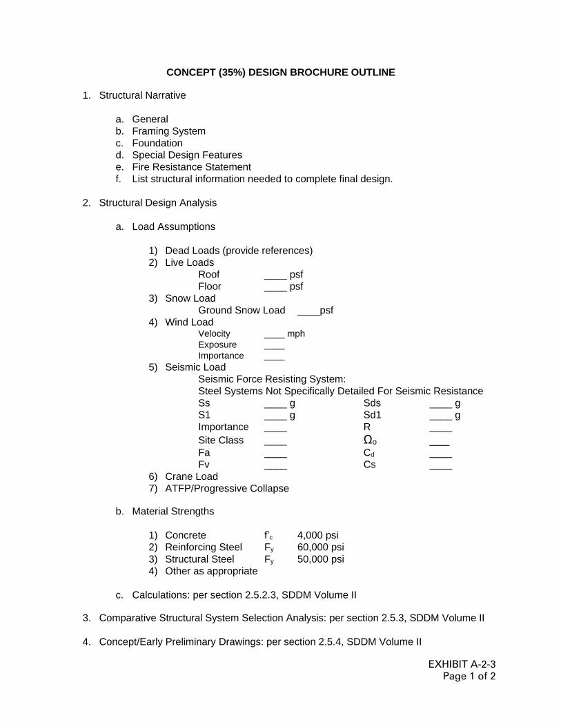
EXHIBIT A-2-3
Page 1 of 2
CONCEPT (35%) DESIGN BROCHURE OUTLINE
1. Structural Narrative
a. General
b. Framing System
c. Foundation
d. Special Design Features
e. Fire Resistance Statement
f. List structural information needed to complete final design.
2. Structural Design Analysis
a. Load Assumptions
1) Dead Loads (provide references)
2) Live Loads
Roof ____ psf
Floor ____ psf
3) Snow Load
Ground Snow Load ____psf
4) Wind Load Velocity ____ mph
Exposure ____
Importance ____
5) Seismic Load
Seismic Force Resisting System:
Steel Systems Not Specifically Detailed For Seismic Resistance
Ss ____ g Sds ____ g
S1 ____ g Sd1 ____ g
Importance ____ R ____
Site Class ____ Ωo ___ Fa ____ Cd ____
Fv ____ Cs ____
6) Crane Load
7) ATFP/Progressive Collapse
b. Material Strengths
1) Concrete f’c 4,000 psi
2) Reinforcing Steel Fy 60,000 psi
3) Structural Steel Fy 50,000 psi
4) Other as appropriate
c. Calculations: per section 2.5.2.3, SDDM Volume II
3. Comparative Structural System Selection Analysis: per section 2.5.3, SDDM Volume II
4. Concept/Early Preliminary Drawings: per section 2.5.4, SDDM Volume II

EXHIBIT A-2-3
Page 2 of 2
5. Outline Specifications: per section 2.5.5, SDDM Volume II
6. Specific Instructions: per section 2.5.6, SDDM Volume II

EXHIBIT A-2-4
Page 1 of 5
STRUCTURAL SECTION
QUALITY CONTROL CHECKLIST
FOR REVIEW OF A-E AND IN-HOUSE FINAL DESIGNS
Project Title: Date:
Designed by: Checked by:
GENERAL
1. Before beginning the review, check to see that you have a complete package,
check A-E Standard Procedures manual and the Specific Instructions
(prepared by SAS) to see if everything required was furnished. If anything is
missing, see the Work Load Manager before proceeding.
2. Before beginning the review, scan the directive, 1391, instructions, prior
review comments, and correspondence.
3. After beginning the review, if it appears that the submittal is unsatisfactory, do
not proceed. Notify the Work Load Manager.
SPECIFICATION CHECK
4. Verify that the required sections of the specifications are in the job by
comparing the specification index to the plans.
5. Verify that the specifications have been properly edited for the project by
reviewing the marked-up sections.
6. Verify that the appropriate review level is indicated for all submittals.
7. Check UFGS 04 20 00, MASONRY structural items to ensure specification is
coordinated with the design. Especially check the testing and/or reinforcing
requirements to verify that they are appropriate.
8. Cross check other section's specifications to ensure that any included
structural information is correct, i.e., UFGS 13 34 19, METAL BUILDING
SYSTEMS for pre-engineered structures, UFGS 13 48 00, SEISMIC
PROTECTION FOR MISCELLANEOUS EQUIPMENT for seismic, etc.
DESIGN CHECK
9. Verify that the design analysis has been signed by both the designer and the
checker.
10. Verify that the live loads are in accordance with criteria, particularly over
mechanical rooms.

EXHIBIT A-2-4
Page 2 of 5
11. Verify that the wind loads are correctly computed and applied.
12. Verify that the seismic loads are correctly calculated and applied.
13. Verify the appropriateness of the seismic design assumptions and details such
as building separation, etc.
14. Verify the design of the major structural elements, i.e. columns, girders,
beams, walls, etc., by spot checking the design of at least one member in
each category. Investigate additional members depending upon the results of
the initial spot check.
15. Verify the design of the lateral load resisting system from the roof diaphragm
to the foundation.
16. Verify that the assumptions used in the foundation analysis are consistent with
the foundation report.
17. Verify the adequacy of the foundation design by spot checking the design of a
least one type of each foundation element used.
18. If computer programs are used, verify that the necessary backup material has
been provided and the assumptions within the backup material are
appropriate.
DRAWING CHECK
19. General Notes:
a) Verify that ALL design loads are indicated, i.e., live, wind, seismic, crane, etc.
b) Verify that the strength of materials used is specified, i.e., A992 steel, 3,000
psi concrete, Grade 60 reinforcing, f'm 1,350 psi compressive strength
masonry.
c) Verify that the type of mortar to be used for masonry walls is specified and
matches the specifications.
d) Verify that concrete reinforcing requirements such as grade of reinforcing and
splice lengths are given (i.e., Grade 60 and 40 bar diameters, respectively).
e) Verify that slab-on-grade thickness and reinforcing requirements are given.
f) Verify that slab-on-grade notes similar to those shown on Exhibit A-2-2 are
provided.
g) Verify notes are provided for attachment of metal deck diaphragms to
supporting members.
h) Verify that notes are provided for details on any design element not otherwise
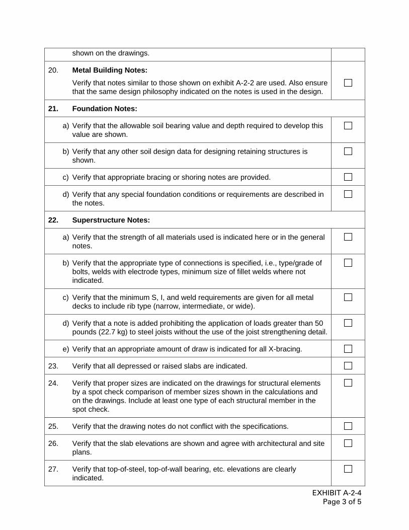
EXHIBIT A-2-4
Page 3 of 5
shown on the drawings.
20. Metal Building Notes:
Verify that notes similar to those shown on exhibit A-2-2 are used. Also ensure
that the same design philosophy indicated on the notes is used in the design.
21. Foundation Notes:
a) Verify that the allowable soil bearing value and depth required to develop this
value are shown.
b) Verify that any other soil design data for designing retaining structures is
shown.
c) Verify that appropriate bracing or shoring notes are provided.
d) Verify that any special foundation conditions or requirements are described in
the notes.
22. Superstructure Notes:
a) Verify that the strength of all materials used is indicated here or in the general
notes.
b) Verify that the appropriate type of connections is specified, i.e., type/grade of
bolts, welds with electrode types, minimum size of fillet welds where not
indicated.
c) Verify that the minimum S, I, and weld requirements are given for all metal
decks to include rib type (narrow, intermediate, or wide).
d) Verify that a note is added prohibiting the application of loads greater than 50
pounds (22.7 kg) to steel joists without the use of the joist strengthening detail.
e) Verify that an appropriate amount of draw is indicated for all X-bracing.
23. Verify that all depressed or raised slabs are indicated.
24. Verify that proper sizes are indicated on the drawings for structural elements
by a spot check comparison of member sizes shown in the calculations and
on the drawings. Include at least one type of each structural member in the
spot check.
25. Verify that the drawing notes do not conflict with the specifications.
26. Verify that the slab elevations are shown and agree with architectural and site
plans.
27. Verify that top-of-steel, top-of-wall bearing, etc. elevations are clearly
indicated.

EXHIBIT A-2-4
Page 4 of 5
28. Verify that sufficient sections are cut on the plans to indicate clearly the details
of construction. Verify that section cuts are properly oriented and properly
referenced. Spot-check as required.
29. Verify by scanning all sections and details that no criteria violations are
present, i.e., slabs resting on footings, etc.
30. Check slab-on-grade jointing to verify compliance with criteria.
31. Verify that stress diagrams are provided for all trusses.
32. Verify that waterproofing is properly shown where required by the soils report.
33. Verify that Plate S-1 has been initialed by both the designer and checker.
34. Verify that appropriate details and notes are provided to indicate CMU
reinforcing, thickness, and lintel requirements. Interior walls must be designed
to span horizontal or vertical under a 10 psf (48.8 kg/m2) lateral load. Verify
that vertical spanning walls are properly supported at the top.
35. Verify that minimum seismic reinforcement is provided in masonry walls if
required. Verify that cavity walls are properly designed and have the
appropriate reinforcement, i.e., bond beams shown, joint reinforcing 3/16
diameter for seismic walls, etc.
36. Verify that masonry walls are properly jointed and that reinforcement is not
continuous through joints except at floor and roof levels. Locations to be
shown on the "S" drawings and "A" drawings with appropriate details.
37. Verify that moment connections are either detailed or that the plans indicate
the moment for which the joint is to be designed.
38. Determine if the following items are required and delete them from the
specifications as appropriate: capillary water barrier, floor hardener,
waterproofing, floor slab reinforcing (increase joint spacing and use 4,000 psi
concrete if omitted), flexural strength concrete (pavement only).
39. Verify that a roof slope greater than 1/4" (6 mm — Army) and 1/4" (6 mm —
Air Force) is provided.
40. Verify that the minimum depth of the footings agrees with the soils report.
41. Verify that the structural details of vaults, arms rooms and secure areas meet
criteria requirements.
42. Verify that perimeter insulation is shown along exterior walls under slabs-on-
grade for all air-conditioned spaces. It should be specified in section UFGS 03
30 00, CAST-IN-PLACE CONCRETE or 03 30 53, MISCELLANEOUS CAST-
IN-PLACE CONCRETE and shown on all "S" plate and "A" plate wall sections.

EXHIBIT A-2-4
Page 5 of 5
43. Verify all cells of CMU walls below grade are filled with grout.
44. Verify that drawings clearly indicate which buildings, by name, are to be
constructed using specification UFGS 13 34 19, METAL BUILDING
SYSTEMS.
45. Verify coordination of mechanical and electrical equipment for support details
on the "S" drawings.
46. Check for details when pipes through exterior foundation walls.
*** End of Section ***