Embed Size (px)
Citation preview

CHAPTER 9
POLYMER MATRIX
NANOCOMPOSITES (PMN)Noraiham Mohamad, Ph.D
Department of Engineering Materials
Faculty of Manufacturing Engineering,
Universiti Teknikal Malaysia Melaka
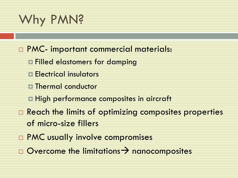
Why PMN?
PMC- important commercial materials:
Filled elastomers for damping
Electrical insulators
Thermal conductor
High performance composites in aircraft
Reach the limits of optimizing composites properties
of micro-size fillers
PMC usually involve compromises
Overcome the limitations nanocomposites
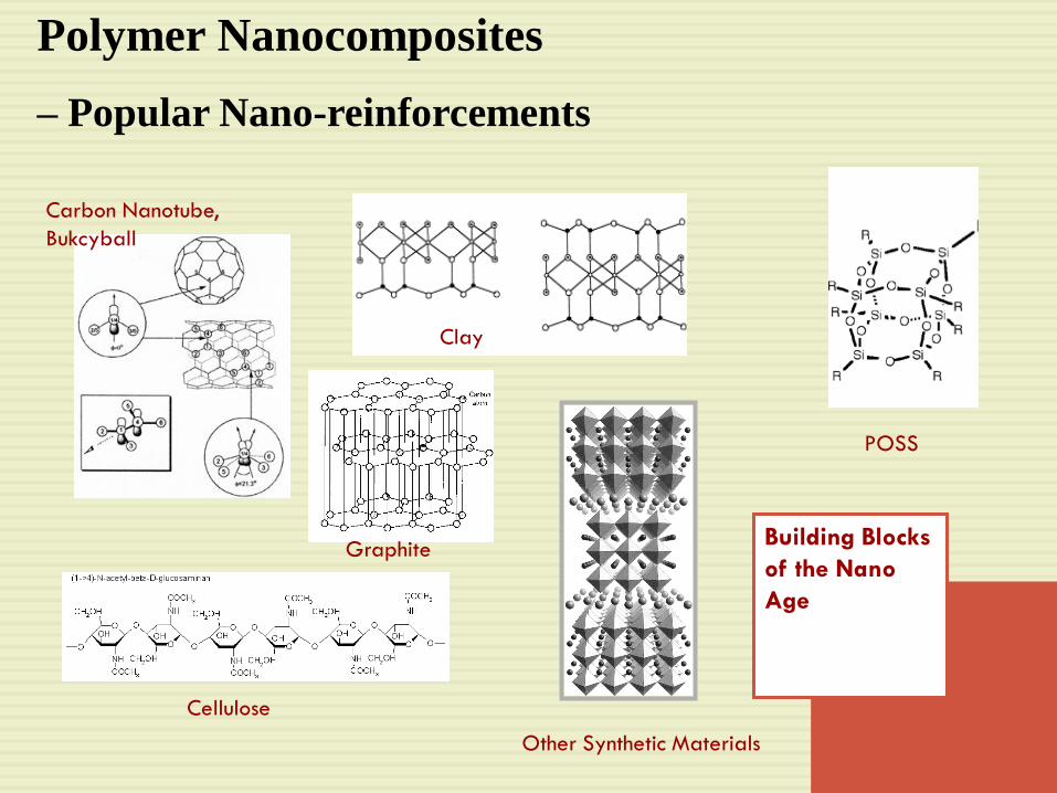
Polymer Nanocomposites
– Popular Nano-reinforcements
Building Blocks
of the Nano
Age
Clay
Other Synthetic Materials
POSS
Graphite
Carbon Nanotube,
Bukcyball
Cellulose

Polymer Nanocomposites (PNC)
Applications
Heat-resistant materials
Light weight and high strength structural materials
Electrical package, conductive polymers.
Barrier Properties
Corrosion resistant, coating or structure
Electro-magnetic field shielding
Selective photo sensitivity, coatings, etc
It is estimated that widespread use of PNCs by car
manufacturers could save over 1.5 billion liters of gasoline
annually and reduce CO2 emissions by nearly 10 billion
pounds!
apresentacoes/orbys_sitep_2007
_v1.ppt5
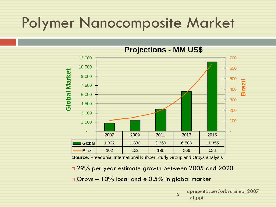
Polymer Nanocomposite Market
29% per year estimate growth between 2005 and 2020
Orbys – 10% local and e 0,5% in global market
Source: Freedonia, International Rubber Study Group and Orbys analysis
Projections - MM US$
-
1.500
3.000
4.500
6.000
7.500
9.000
10.500
12.000
Glo
ba
l M
ark
et
-
100
200
300
400
500
600
700
Bra
zil
Global 1.322 1.830 3.660 6.508 11.355
Brazil 102 132 198 366 638
2007 2009 2011 2013 2015
apresentacoes/orbys_sitep_2007_v1.
ppt
6
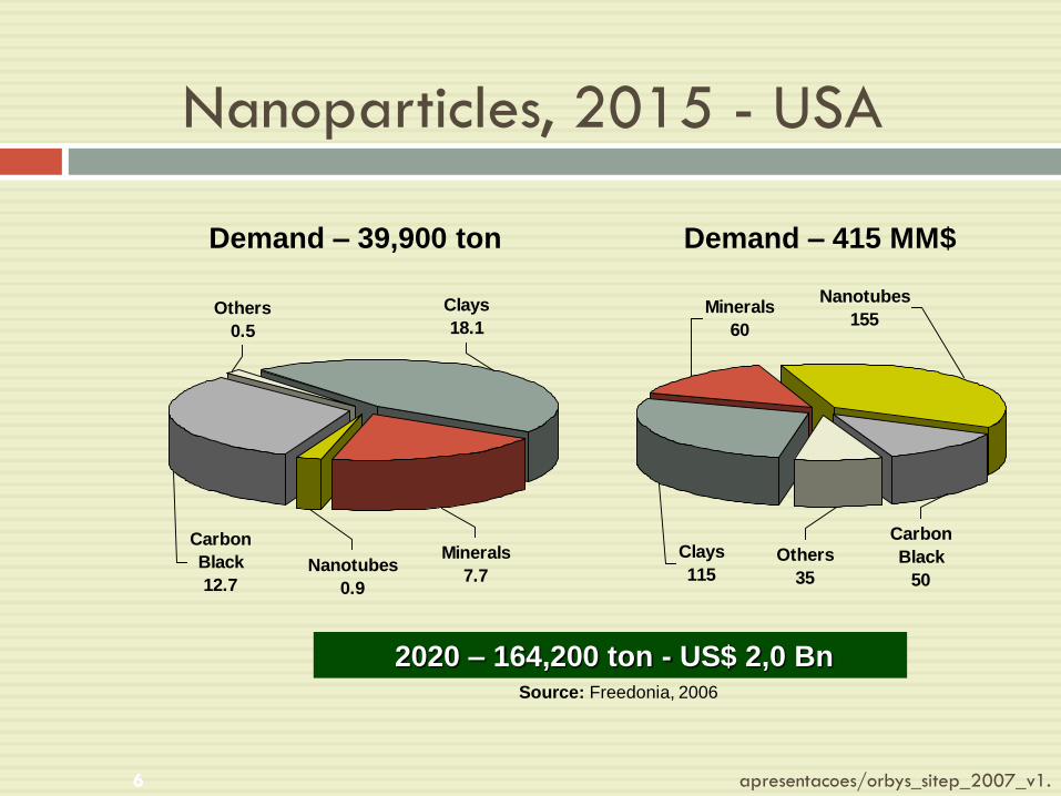
Nanoparticles, 2015 - USA
Others
0.5
Minerals
7.7Nanotubes
0.9
Carbon
Black
12.7
Clays
18.1
Others
35
Minerals
60
Nanotubes
155
Carbon
Black
50
Clays
115
2020 – 164,200 ton - US$ 2,0 Bn
Demand – 39,900 ton Demand – 415 MM$
Source: Freedonia, 2006

apresentacoes/orbys_sitep_2007
_v1.ppt7
Nanocomposites
Multiphase: 1 or more phases < 100nm
Properties unachievable with traditional materials
Types of nanocomposites:
Nano-nanocomposites
Ceramic nanocomposites
Metal-Nanopolymer composites
Polymer nanocomposites

What is PMN?
Nanoscale filled polymer composites in which the
filler is < 100 nm in at least one dimension

Causes in the Revolution of PMN
Unprecedented combinations of properties have been observed in some PMN.
0.04% mica-type silicates (MTS) in epoxy increase modulus below Tg by 58% and modulus in rubbery region by 450%
Discovery of carbon nanotube in the early 1990s
Strength & electrical properties of CNT different from graphiteoffering possibilities for new composites
Significant development in the chemical processing of nanoparticles
In situ processing of nanocomposites led to unprecedented control over morphology of composites
Create almost unlimited ability to control interface between matrix and filler

What is so unique to nanofillers?
Small size of the fillers
Very small nanoparticles do not scatter light significantly- possible to make composites with altered electrical or mechanical properties that retain optical clarity
Do not create large stress concentration – do not compromise the ductility of the polymer
Lead to unique properties of the particles themselves –SWNTs are essentially molecules, free from defects, have modulus as high as 1 TPa, strength as high as 500 GPa.

Leads to an exceptionally large interfacial area in
composites
Interface controls the degree of interaction between
fillers and polymers; control properties
Greatest challenge: Learn to control the interface!
What is so unique to nanofillers?

What is interfacial region?
Is the region beginning at the point in the fiber at
which the properties differ from those of the bulk
filler and ending at the point in the matrix at which
the properties become equal to those of the matrix
Can be a region of altered chemistry, altered
polymer chain mobility, altered degree of cure &
altered crystallinity
Interface size- as small as 2 nm & as large as ~50
nm

Nanoscale fillers
Many shapes and sizes
Into 3 categories
Fiber or tube fillers- diameter < 100 nm and aspect ratio of at least 100; aspect ratio can be as high as 106 (CNT)
Platelike nanofillers- layered materials typically with thickness on the order of 1 nm & aspect ratio in the other two dimensions of at least 25
Three dimensional (3D) nanofillers- relatively equiaxedparticles < 100 nm in their largest dimension

14
Carbon Nanotubes
Structure of simple wall nanotubes (a, b, c)
and multiple wall nanotube
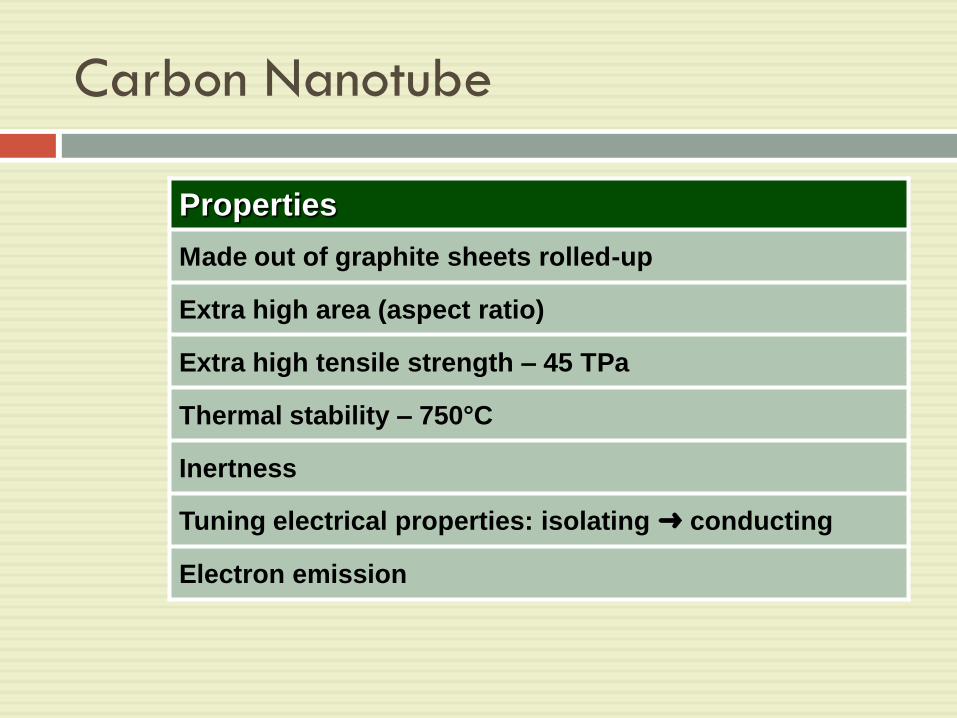
Carbon Nanotube
Properties
Made out of graphite sheets rolled-up
Extra high area (aspect ratio)
Extra high tensile strength – 45 TPa
Thermal stability – 750°C
Inertness
Tuning electrical properties: isolating ➜ conducting
Electron emission

Carbon Nanotube
Application
Polymer
nanocomposite
Ultra resistant, conductive –
Automotive, Aeronautics
Nanofoams Strong light weight materials
Future
Electrical energy storage
Hydrogen storage
Large Area Display

Carbon Nanotube
Difficulties & Barriers
High Price
Precisely determinable structure
(type, dimensions, properties, etc)
Potential health risk (strong fibrous nature)
Single nanotubes, not bulk material
Toxicity + Inertness
apresentacoes/orbys_sitep_2007
_v1.ppt18
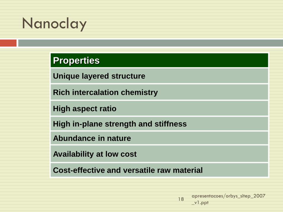
Nanoclay
Properties
Unique layered structure
Rich intercalation chemistry
High aspect ratio
High in-plane strength and stiffness
Abundance in nature
Availability at low cost
Cost-effective and versatile raw material

Processing of PMN
Key limitations in commercialization- processing
Primary difficult: proper dispersion of the fillers
Without proper dispersion & distribution;
The high surface area is compromised
The aggregates can act as defects; limit the properties
Distribution- describes the homogeneity of
nanofillers throughout samples
Dispersion- describes the level of agglomeration

The schematic representation of mixing (top row, left to right): bad dispersion and
distribution; bad dispersion, but good distribution; (bottom row, left to right): good
dispersion, but bad distribution, and good dispersion and distribution

Nanotube/Polymer Composites
Processing

Nanotube/Polymer Composites
The processing of nanotube/polymer composites is
still in its infancy
Although produced commercially; literature
describing the process is limited
Significant issues:
Purification
Dispersion
Bulk processing

Most critical processing parameters
Ability to disperse SWNT and MWNT;
Clumps or agglomerations of NT – create defect sites that will initiate failure & limit the efficiency of nanotubes to carry load
CVD grown MWNT- easily dispersed & less agglomerated increase modulus & strength of polystyrene without compromising strain-to-failure factor
Not fully purified & not well dispersed arc-discharge-grown MWNT did not show the increase in toughness observed for well-dispersed
Methods of processing
Direct placing of resins onto NT thin film (Small-
scale composites)
Dispersion is carried out; primarily by sonication- best
solvent for SWNT are NMP, DMF,
hexamethylphosphoramide, cyclopentane,
tetramethylene sulfoxide and -caprolactone (all strong
Lewis bases without hydrogen donors)
Drying dispersion on a glass slide thin film of SWNT
Placing resin directly onto thin film

Direct mixing of NT and Polymers at TR
Mixing of both NT and polymer in the presence of solvent; with help of a surfactant
Eg. SWNT dispersed in ethanol and then mixed with an epoxy resin
Eg. CVD-grown MWNT dispersed in toluene with dissolved PS cast into film
Eg. NT dispersed directly into liquid urethane acrylatepolymer or methylmethacrylate monomer, or epoxy resin curing or polymerization
Methods of processing
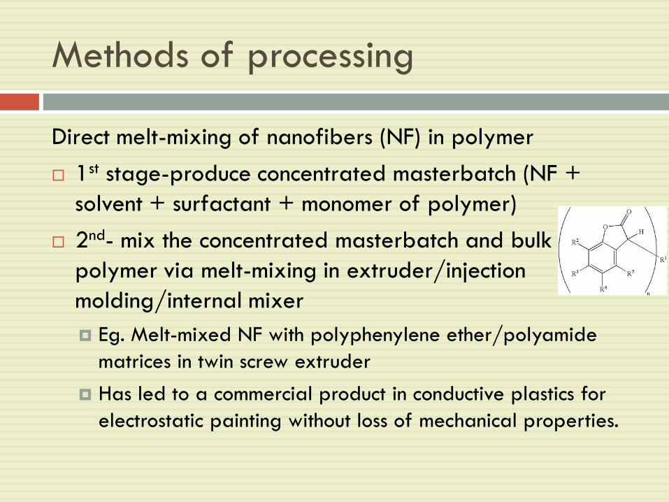
Direct melt-mixing of nanofibers (NF) in polymer
1st stage-produce concentrated masterbatch (NF +
solvent + surfactant + monomer of polymer)
2nd- mix the concentrated masterbatch and bulk
polymer via melt-mixing in extruder/injection
molding/internal mixer
Eg. Melt-mixed NF with polyphenylene ether/polyamide
matrices in twin screw extruder
Has led to a commercial product in conductive plastics for
electrostatic painting without loss of mechanical properties.
Methods of processing

Layered Filler-Polymer Composite
Processing
apresentacoes/orbys_sitep_2007
_v1.ppt28
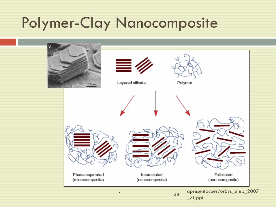
Polymer-Clay Nanocomposite
.

Polymer-Clay Nanocomposites
Application
Automotive Components
Packaging Materials
Coatings and Pigments
Electro materials
Drug Delivery
Sensors and Medical Devices
Building Materials

Polymer-Clay Nanocomposites
Difficulties & Barriers
Mechanical properties of individual silicate layers are
not known
Processing in large scale
Lack of commercially available and thermally stable
organoclays

Layered filler-polymer composite
processing
1980s- clay/Nylon 6 composites were first commercialized
Polymers interact strongly with montmorillonite
Clay surface can act as an initiator for polymerization
Steps in composites production:
Open clay galleries & match polarity of polymer
Intercalation of organically modified clay
XRD analysis- intercalation/exfoliation
Processing of nanocomposites by traditional melt-processing method
1. Open clay galleries & match
polarity
Objective: to make sure polymers or monomers
intercalate between clay layers
Done by exchanging an organic cation for an
inorganic cation
Larger organic cations swell the layers and increase
the hydrophobic properties of the clay
Resulting in: organically modified clay or known as
“organoclay”

2. Intercalation of Organoclay with
polymer
By Solution Processing
Dispersion of both organoclay and polymer in a common solution
Highly polar polymers (Nylon & polyimides)- easily intercalated than nonpolar polymers (PP) Polar polymers have higher affinity for the polar clay
galleries
In-situ polymerization- intercalates monomer directly into organically modified clay galleries
Monomer can either: Absorb onto the layer surface or
Be anchored by free radical techniques
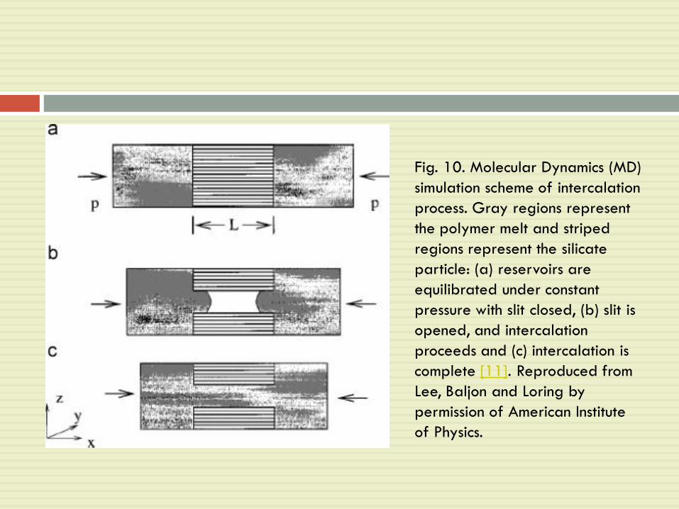
Fig. 10. Molecular Dynamics (MD)
simulation scheme of intercalation
process. Gray regions represent
the polymer melt and striped
regions represent the silicate
particle: (a) reservoirs are
equilibrated under constant
pressure with slit closed, (b) slit is
opened, and intercalation
proceeds and (c) intercalation is
complete [11]. Reproduced from
Lee, Baljon and Loring by
permission of American Institute
of Physics.

Fig. 26. Snapshot at 1000 ps of
octadecyltrimethyl–clay. Clay platelets are
represented by a stick model and each surfactant
chain is represented by a ball model with a
different color for better visualization and
includes nitrogen (large ball), united carbon (small
ball) of hydrocarbon chain, and oxygen (medium
ball) [105]. Reproduced from Paul, Zeng, Yu and
Lu by permission of Elsevier Science Ltd.
Fig. 27. Snapshot of the 350,840-atom supercell after 0.5 ns
of MD simulation showing a perspective view of the
rectilinear supercell, the clay sheets exhibiting gentle
undulations. The color scheme is C gray, H white, O red, N
blue, Si orange, Al green, Mg magenta and Na brown [107].
Reproduced from Greenwell, Harvey, Boulet, Bowden,
Coveney and Whiting by permission of American Chemical
Society.
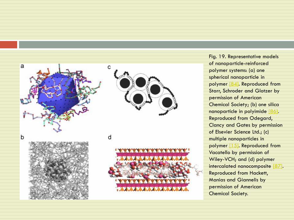
Fig. 19. Representative models
of nanoparticle-reinforced
polymer systems: (a) one
spherical nanoparticle in
polymer [84]. Reproduced from
Starr, Schroder and Glotzer by
permission of American
Chemical Society; (b) one silica
nanoparticle in polyimide [86].
Reproduced from Odegard,
Clancy and Gates by permission
of Elsevier Science Ltd.; (c)
multiple nanoparticles in
polymer [15]. Reproduced from
Vacatello by permission of
Wiley-VCH; and (d) polymer
intercalated nanocomposite [87].
Reproduced from Hackett,
Manias and Giannelis by
permission of American
Chemical Society.
Intercalation of Organoclay with
polymer
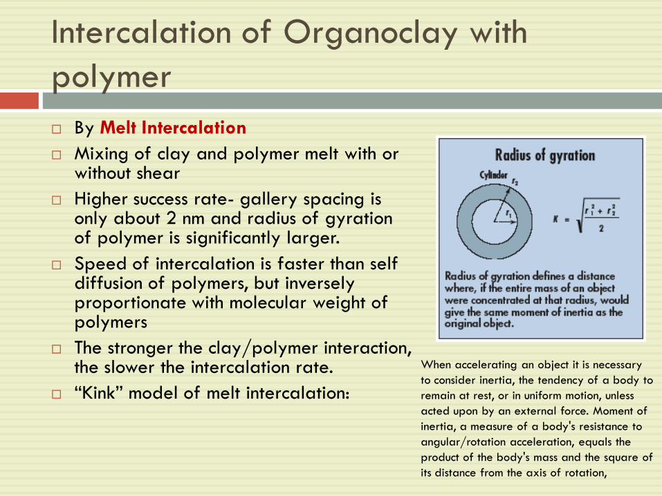
By Melt Intercalation
Mixing of clay and polymer melt with or without shear
Higher success rate- gallery spacing is only about 2 nm and radius of gyration of polymer is significantly larger.
Speed of intercalation is faster than self diffusion of polymers, but inversely proportionate with molecular weight of polymers
The stronger the clay/polymer interaction, the slower the intercalation rate.
“Kink” model of melt intercalation:
When accelerating an object it is necessary
to consider inertia, the tendency of a body to
remain at rest, or in uniform motion, unless
acted upon by an external force. Moment of
inertia, a measure of a body's resistance to
angular/rotation acceleration, equals the
product of the body's mass and the square of
its distance from the axis of rotation,

“Kink” model of melt intercalation
Layer flexibility control the mechanism of intercalation
Sufficient force causes kink to form in clay sheet (a form of compression failure)
Then, polymer can penetrate into new space between the layers
Kink can propagate along the layer more polymer intercalated
Fast intercalation rate:
Enhance by space created by kinking
Depend on layers flexibility (Low modulus layers, kink more easily)
Intercalation of Organoclay with
polymer
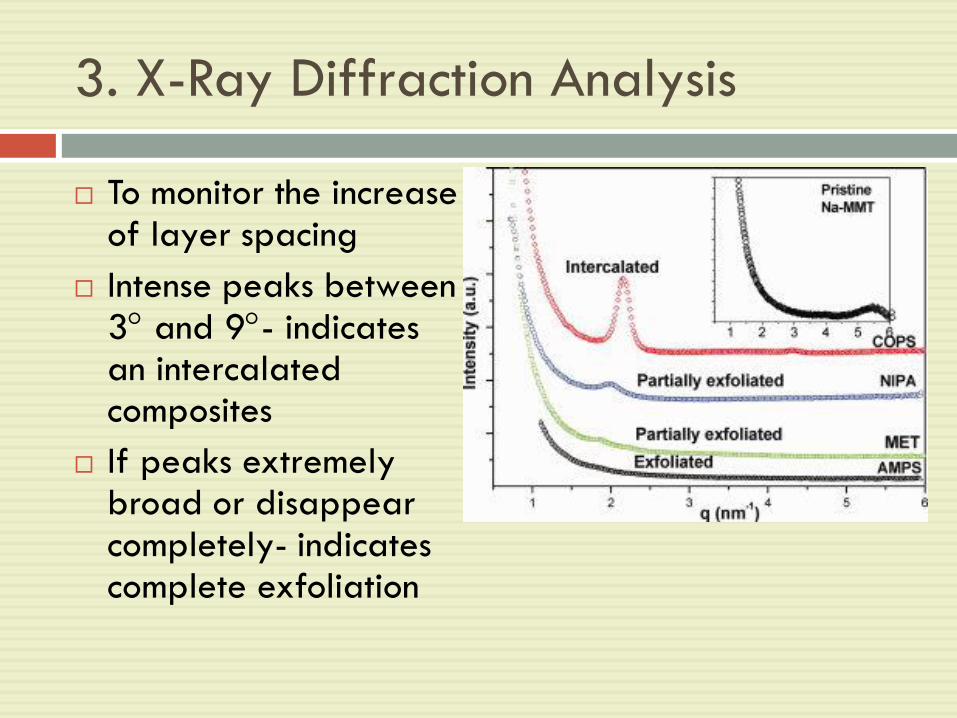
To monitor the increase of layer spacing
Intense peaks between 3 and 9- indicates an intercalated composites
If peaks extremely broad or disappear completely- indicates complete exfoliation
3. X-Ray Diffraction Analysis


4. Processing of Nanocomposites by
Traditional Melt-processing
Final processing-important in determining the final properties
Mixing facilities- nanoscale dispersion; lead to clay and/or polymer chain alignment
Degree of shear during molding determines: Degree of clay layer alignment
Degree of crystalline alignment
Eg. Extruded Nylon sheet with a draw ratio of 4:1- Had higher modulus than sheet processed by injection
molding
May be due to higher degree of platelet and crystallite allignment
draw ratio: distance the plastic sheet is stretched
vertically divided by the distance it is stretched
horizontally.
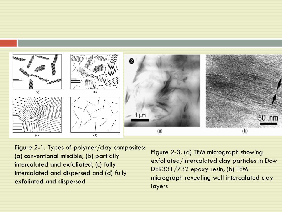
Figure 2-1. Types of polymer/clay composites:
(a) conventional miscible, (b) partially
intercalated and exfoliated, (c) fully
intercalated and dispersed and (d) fully
exfoliated and dispersed
Figure 2-3. (a) TEM micrograph showing
exfoliated/intercalated clay particles in Dow
DER331/732 epoxy resin, (b) TEM
micrograph revealing well intercalated clay
layers
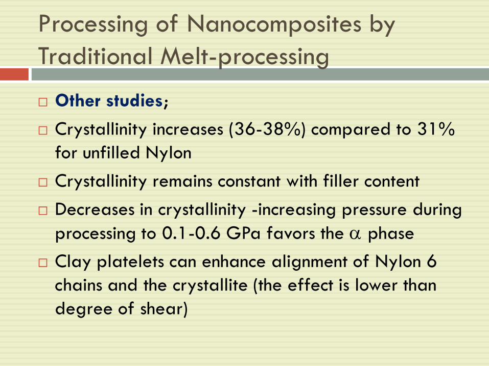
Processing of Nanocomposites by
Traditional Melt-processing
Other studies;
Crystallinity increases (36-38%) compared to 31%
for unfilled Nylon
Crystallinity remains constant with filler content
Decreases in crystallinity -increasing pressure during
processing to 0.1-0.6 GPa favors the phase
Clay platelets can enhance alignment of Nylon 6
chains and the crystallite (the effect is lower than
degree of shear)
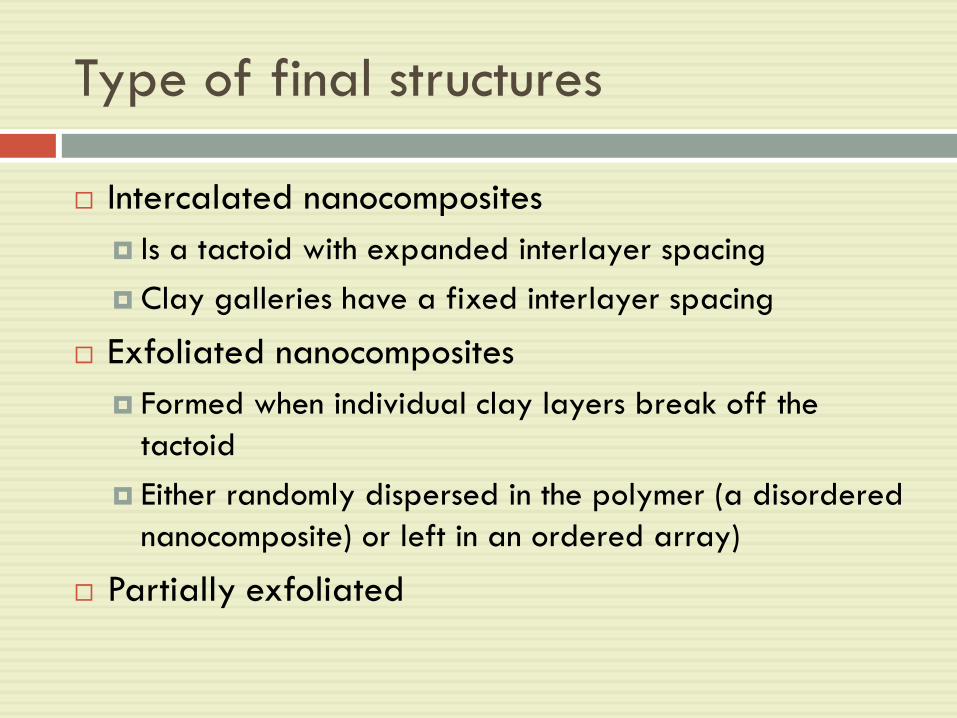
Type of final structures
Intercalated nanocomposites
Is a tactoid with expanded interlayer spacing
Clay galleries have a fixed interlayer spacing
Exfoliated nanocomposites
Formed when individual clay layers break off the
tactoid
Either randomly dispersed in the polymer (a disordered
nanocomposite) or left in an ordered array)
Partially exfoliated
Type of matrices
Polyamide: Nylon-6; Nylon-12
Polyimide
Nonpolar polymers: Polypropylene and polyethylene
Liquid-crystal matrices
Polymetylmethacrylate/polystyrene
Epoxy and polyurethane
Polyelectrolyte
Rubber
Others

apresentacoes/orbys_sitep_2007
_v1.ppt46
Orbys Technology
Latex
Clay
Nanocomposite
Dispersion
What is it?
Nanocomposites obtained through colloidal construction
Prepared by mixture, by adding to exfoliated clay and natural or synthetic latex.
Other routes: melt intercalation & in situ polymerization

Nanoparticle/Polymer Composites
Processing
Nanoparticle/Polymer Composites
Processing
3 general ways:
Direct mixing of polymer and nanoparticles either
as discrete phases or in solution
In-situ polymerization in the presence of
nanoparticles
Both in-situ formation of nanoparticles and in-situ
polymerization- results in hybrid nanocomposites
due to intimate mixing of two particles

Direct Mixing
Two roll mill
PP and nanoscale silica- samples with more than 20wt% filler could not be drawn
Twin-screw extruder
Nanoscale silica/PP composites-successful dispersion after modification of silica interface to increase compatibility with the matrix
Brabender high-shear mixer- successfully used to mix nanoscale alumina with PET, LDPE
Thermal spraying-successful in processing nanoparticles-filled Nylon
Traditional melt-mixing:
Adv: the fastest method for producing new products (traditional methods available)
Disadv: for some polymers, viscosity increases rapidly with the addition of significant volume fraction of nanofiller (can limit the practicality of the processing method)
Solution Mixing
Limitations of melt-mixing can be overcome if both polymers and nanoparticles are dissolved or dispersed in solution
Allows modification of particle surface without drying, reduce particle agglomeration
The nanoparticle/polymer solution can be;
Cast into a solid
nanoparticle/polymer can be isolated from solution by solvent evaporation or precipitation
Further processing- by conventional techniques

In-situ polymerization
Nanoscale particles are dispersed in the monomer or monomer solution
Resulting mixture is polymerized by standard polymerization methods
Potential to graft the polymer onto the particle surface
Eg. of nanocomposites via this process;
Silica/Nylon6
Silica/poly 2-hydroxyethylmethacrylate
Alumina/polymethylmethacrylate
Titania/PMMA
CaCO3/PMMA
Key to in-situ polymerization- appropriate dispersion of filler in the monomer
Often requires modification of the particle surface
Dispersion is easier since it is in liquid rather than in a viscous melt
Settling process is more rapid

In-Situ Particle Processing-
Ceramic/Polymer Composites
In-situ sol-gel processing of the particles inside the
polymer
Successfully to produce polymer nanocomposites
with silica & titania in a range of matrices
Overall reaction for silica from tetrathylorthosilicate
(TEOS) :
Si(OC2H5)4 + excess H2 SiO2 + 4C2H5OH
Few approach to form composites
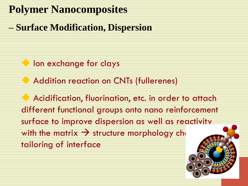
Polymer Nanocomposites
– Surface Modification, Dispersion
Ion exchange for clays
Addition reaction on CNTs (fullerenes)
Acidification, fluorination, etc. in order to attach
different functional groups onto nano reinforcement
surface to improve dispersion as well as reactivity
with the matrix structure morphology change &
tailoring of interface

Focus : Carbon Nanotube Functionalization
R1NHCH2C(=O)OH + R2CH=O
DMF, 130 oC
120 hN
H2C CH
R1R2
+_- H2O, CO2
N
R2
R1
x
SWNTsSWNT
R1= -CH2(CH2)6CH3, -CH2CH2OCH2CH2OCH2CH2OCH3
R2= H, OCH3,
ROC(=O)N3 + SWNT
- N2
160 oCODCB
SWNT [>NC(=O)OR]x
R = tert-Butyl, Ethyl, oligoether groups
Azomethine Ylides M. Prato, A. Hirsch et al., 2001
R
N2+BF4
-
R
NH2
RSWNT
xBu4N
+BF4
-CH3CN
SWNTs, -1 V (CH3)2CHCH2CH2ONO
SWNTs
ODCB / CH3CN, 2:1
65 oC
R = tert-Butyl, halogen, COOH, NO2, COOH, CO2CH3 etc.
Aryl Diazonium Salts, J. Tour et al., 2001
[F]x-SWNTs
F2/H2
SWNTs heat
SWNTs + RC(=O)OO(=O)CR heat
- CO2
SWNTs[R]x-
R = C11H23, C6H5, CH2CH2COOH
Fluorination
J. L. Margrave et al., 1998
Acyl Peroxides
V.N.Khabashesku et al., 2002
Nitrenes A. Hirsch et al., 2001, 2003
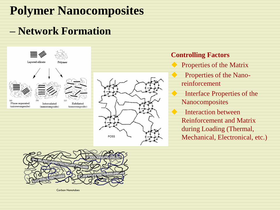
Polymer Nanocomposites
– Network Formation
POSS
Carbon Nanotubes
Controlling Factors
Properties of the Matrix
Properties of the Nano-
reinforcement
Interface Properties of the
Nanocomposites
Interaction between
Reinforcement and Matrix
during Loading (Thermal,
Mechanical, Electronical, etc.)

Conflicting Property Reports
Conflicts Result from Differences in
Matrix Polymer Repeating Unit
Relative Mobility of Nano-reinforcement Compared with Matrix
Degree of Crosslinking
Polymerization Mechanism
Nano-reinforcement
Surface Treatment
Degree of Dispersion
etc.
De-convolution
Simple Model System
Experimental Condition
Raw Materials Selection
Molecular Dynamics
the Future …
Properties Design
Microscopic Morphology Control
Optimum Interface Design
Mechanosynthesis of Polymer Chains