Embed Size (px)
Citation preview

Northwest AirlinkCANADAIR REGIONAL JET FLIGHT CREW OPERATING MANUAL—Volume 1
Pinnacle Airlines
CHAPTER 9
CONTENTS
Page
FIRE PROTECTION
GENERAL......................................................................... 9-1SYSTEM DESCRIPTION................................................. 9-1
Fire Detection and Extinguishing Systems ................ 9-2CONTROLS AND INDICATIONS............................... 9-15
Fire Panel ................................................................ 9-15Cargo Fire Panel...................................................... 9-18LH and RH ENG FIRE PUSH Switchlights........... 9-20Glareshield .............................................................. 9-20Landing Gear Control Panel ................................... 9-22Lavatory Smoke Detector ....................................... 9-24EICAS Indications .................................................. 9-26Circuit Breakers ...................................................... 9-29
Revision 1—January 2003 9-i

Northwest AirlinkCANADAIR REGIONAL JET
FLIGHT CREW OPERATING MANUAL—Volume 1
Pinnacle Airlines
INTENTIONALLY LEFT BLANK
9-ii Revision 1—January 2003

Northwest AirlinkCANADAIR REGIONAL JET FLIGHT CREW OPERATING MANUAL—Volume 1
Pinnacle Airlines
ILLUSTRATIONS
Figure Title Page
9-1 Engine Firex Monitor System............................ 9-39-2 APU Firex Monitor System ............................... 9-69-3 Automatic Fire Extinguishers ............................ 9-99-4 Cargo Compartment Firex Monitor System ... 9-119-5 Portable Fire Extinguishers............................. 9-139-6 Fire Panel ........................................................ 9-159-7 Cargo Fire Panel ............................................. 9-189-8 Glareshield ...................................................... 9-219-9 Landing Gear Control Panel ........................... 9-239-10 Lavatory Smoke Detector ............................... 9-25
Revision 1—January 2003 9-iii

Northwest AirlinkCANADAIR REGIONAL JET
FLIGHT CREW OPERATING MANUAL—Volume 1
Pinnacle Airlines
INTENTIONALLY LEFT BLANK
9-iv Revision 1—January 2003

Northwest AirlinkCANADAIR REGIONAL JET FLIGHT CREW OPERATING MANUAL—Volume 1
Pinnacle Airlines
TABLES
Table Title Page
9-1 Fire and Smoke Alerting Indications .............. 9-269-2 Power Supply and
Circuit-Breaker Summary............................... 9-29
Revision 1—January 2003 9-v
Northwest AirlinkCANADAIR REGIONAL JET
FLIGHT CREW OPERATING MANUAL—Volume 1
Pinnacle Airlines
INTENTIONALLY LEFT BLANK
9-vi Revision 1—January 2003

Northwest AirlinkCANADAIR REGIONAL JET FLIGHT CREW OPERATING MANUAL—Volume 1
Pinnacle Airlines
CHAPTER 9FIRE PROTECTION
GENERAL
Fire protection includes those fixed and portable components whichidentify fire and overheat conditions, as well as provide warnings offire, overheat, and smoke in the airplane. The fire protection systemalso stores the fire-extinguishing agent and applies it to all protectedareas of the airplane when needed.
The fire protection system provides the ability to detect and extin-guish a fire in the engine nacelles and in the auxiliary power unit(APU) compartment. An overheat detection system, in the jetpipeand pylon areas of each engine, permits the flight crew to monitorany overheat condition in those areas. The main gear wheel wellshave a similar overheat detection system. The airplane is equippedwith a lavatory smoke detector and an automatic built-in fire extin-guisher. The cargo compartment also has detect ion andextinguishing systems.
Both the detection and extinguishing systems permit the flight crewto test and monitor for possible system faults.
SYSTEM DESCRIPTION
The fire protection system includes fire detection and extinguishingsystems. Fire detection is provided for the following areas:
● Engine (overheat)
● Auxiliary power unit (overheat)
● Lavatory (smoke only)
● Cargo compartment (smoke only)
● Main landing gear (overheat only)
Revision 1—January 2003 9-1

Northwest AirlinkCANADAIR REGIONAL JET
FLIGHT CREW OPERATING MANUAL—Volume 1
Pinnacle Airlines
Fire extinguishing systems are provided for the following:
● Engine fire extinguishing
● APU fire extinguishing
● Portable fire extinguishing
● Lavatory fire extinguishing
● Cargo fire extinguishing
FIRE DETECTION AND EXTINGUISHING SYSTEMS
Engine and APU
The engine and APU fire/overheat detection system determines if afire or overheat condition occurs in the engine nacelles, jetpipe andpylon areas, and the APU. Each fire and overheat detection systemconsists of dual heat sensing elements, designated loops A and B,which are mounted parallel to each other in the following areas (Fig-ure 9-1):
● Left and right nacelles, zone A (fire detection)
● Left and right jetpipes and pylons, zone B (overheatdetection)
● APU compartment (fire detection)
The fire-extinguishing systems store the fire-extinguishing agentand apply it to the necessary areas. Two engine fire-extinguishingbottles are in the rear fuselage equipment bay. The APU fire-extin-guishing bottle is on the APU support structure in the rear fuselageequipment compartment. The bottles use Halon and are pressurizedwith nitrogen. A bottle pressure gage reveals bottle pressure. Whenthe bottle pressure is low, a caution message is shown on the EICASprimary display.:
9-2 Revision 1—January 2003

Northwest AirlinkCANADAIR REGIONAL JET FLIGHT CREW OPERATING MANUAL—Volume 1
Pinnacle Airlines
The discharge lines are interconnected to allow discharge of bothbottles into one engine, if needed. The FIRE DETECTION/FIREXMONITOR panel permits the flight crew to test squib circuit conti-nuity and monitor Firex bottle pressure.
MLG BAY OVERHEATDETECTION LOOP
10TH STAGEBLEED AIR SOV
10TH STAGEBLEED AIR SOV
14TH STAGEBLEED AIRSOV
HYD SOV
ENGINESENSORELEMENTS
JETPIPESENSORELEMENTS(A & B)
FUEL SOV
14TH STAGEBLEED AIR
SOV
HYD SOV
ENGINESENSOR
ELEMENTS
JETPIPESENSOR
ELEMENTS(A & B)
FUEL SOV
PYLONSENSORELEMENTS
PYLONSENSOR
ELEMENTS
NO. 2ENGINEFIREX
BOTTLE
NO. 1ENGINEFIREX
BOTTLE
TEST
1 2 APUBOTTLE
CARGOBOTTLEENGINE BOTTLE
NORM
TEST
NORM
TEST 1
TEST
WARNENGJET
APU
FIREX MONITOR
RHJETENG
FAIL
NORMTEST 2
ABOTH
B
FIRE DETECTIONLH
BOTTLE 1ARMED
PUSH TODISCH
LH ENGFIREPUSH
APUFIREPUSH
BOTTLEARMED
PUSH TODISCH
BOTTLE 2ARMED
PUSH TODISCH
RH ENGFIREPUSH
Figure 9-1 Engine Firex Monitor System
Revision 1—January 2003 9-3
Northwest AirlinkCANADAIR REGIONAL JET
FLIGHT CREW OPERATING MANUAL—Volume 1
Pinnacle Airlines
If a fire occurs while the APU is unattended on the ground, the APUfire-extinguishing detection system automatically shuts down theAPU and activates the APU fire-extinguishing system. A fire warn-ing horn, in the aft accessory section, operates when the Firex bottlesquib is tested with the APU shut down or if an APU fire is detectedwhile on the ground.
Fire and Overheat Control Unit
The fire and overheat control unit monitors two sensing elementloops for a change in resistance that accompanies a heat increase.Both loops must detect a heat increase to trigger fire alerting on theEICAS. A failure of one loop is indicated by a FAIL message on theEICAS. Deselecting the affected loop enables the remaining loop togive fire and overheat alerting.
Engine Fire Extinguishing
When fire occurs in an engine (see Figure 9-1):
MASTER WARNING and LH or RH FIRE PUSH switchlightsilluminate.
● Firebell sounds.
● MASTER WARNING switchlight is pressed:
❍ Firebell silences.
❍ MASTER WARNING switchlight extinguishes and resets.
● Respective thrust lever is set to the SHUTOFF position:
❍ Respective LH or RH FIRE PUSH switchlight remainsilluminated.
● The illuminated ENG FIRE PUSH switchlight is pressed:
❍ BOTTLE 1 or 2 ARMED PUSH TO DISCH switchlightilluminates.
9-4 Revision 1—January 2003

Northwest AirlinkCANADAIR REGIONAL JET FLIGHT CREW OPERATING MANUAL—Volume 1
Pinnacle Airlines
❍ Squibs are armed.
❍ Engine fuel feed shutoff valve closes.
❍ Bleed-air shutoff valve closes.
❍ Hydraulic shutoff valve closes.
❍ Engine-driven generator shuts down.
● The onside BOTTLE ARMED PUSH TO DISCH switchlightis pressed:
❍ Bottle 1 or 2 squib fires.
❍ Firex extinguishing agent discharges.
❍ The respective ENG BOT 1 or 2 LO message appears onEICAS.
If a fire or overheat condition in the engine persists:
● LH or RH ENG FIRE PUSH switchlight remains illuminated.
● The remaining BOTTLE ARMED PUSH TO DISCH switch-light is pressed:
❍ The respective bottle squib fires.
❍ Firex extinguishing agent discharges.
❍ The respective ENG BOT LO message appears on EICASwith MASTER CAUTION.
Revision 1—January 2003 9-5
Northwest AirlinkCANADAIR REGIONAL JET
FLIGHT CREW OPERATING MANUAL—Volume 1
Pinnacle Airlines
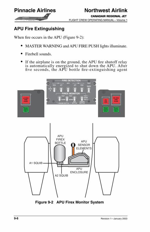
APU Fire Extinguishing
When fire occurs in the APU (Figure 9-2):
● MASTER WARNING and APU FIRE PUSH lights illuminate.
● Firebell sounds.
● If the airplane is on the ground, the APU fire shutoff relayis automatically energized to shut down the APU. Afterfive seconds, the APU bottle fire-extinguishing agent
APUFIREX
BOTTLE
A1 SQUIB
A2 SQUIB
APUENCLOSURE
APUSENSOR
ELEMENTS
TEST
1 2 APUBOTTLE
CARGOBOTTLEENGINE BOTTLE
NORM
TEST
NORM
TEST 1
TEST
WARNENGJET
APU
FIREX MONITOR
RHJETENG
FAIL
NORMTEST 2
ABOTH
B
FIRE DETECTIONLH
BOTTLE 1ARMED
PUSH TODISCH
LH ENGFIREPUSH
APUFIREPUSH
BOTTLEARMED
PUSH TODISCH
BOTTLE 2ARMED
PUSH TODISCH
RH ENGFIREPUSH
Figure 9-2 APU Firex Monitor System
9-6 Revision 1—January 2003

Northwest AirlinkCANADAIR REGIONAL JET FLIGHT CREW OPERATING MANUAL—Volume 1
Pinnacle Airlines
automatically discharges. If the aircraft is in flight, theAPU automatically shuts down.
● MASTER WARNING switchlight is pressed:
❍ Firebell silences.
❍ MASTER WARNING switchlight extinguishes and resets.
● APU FIRE PUSH switchlight is pressed:
❍ BOTTLE ARMED PUSH TO DISCH switchlight illuminates.
❍ If on the ground, the APU is shut down if the automaticshutdown was not successful.
❍ If airborne, the APU shuts down.
❍ APU squibs are armed.
❍ APU bleed-air valve closes.
❍ APU fuel valve closes.
● BOTTLE ARMED PUSH TO DISCH switchlight is pressed:
❍ APU bottle squib fires.
❍ Firex extinguishing agent discharges.
❍ APU BTL LO message appears on EICAS with MASTERCAUTION.
Main Landing Gear
The main landing gear overheat detection system consists of single-loop sensing elements in both main landing gear bays as well as adual-channel overheat detection unit. The overheat detection unitcontinuously monitors the heat-sensing elements. Any overheat con-dition or system fault is displayed on the EICAS with a possibleaccompanying aural message.
Revision 1—January 2003 9-7

Northwest AirlinkCANADAIR REGIONAL JET
FLIGHT CREW OPERATING MANUAL—Volume 1
Pinnacle Airlines
The overheat detection system is tested from the flight compartmentby selectively simulating an overheat condition and a system faultcondition. Test result messages are displayed on the EICAS.
Four heat-sensitive fusible plugs in each wheel release excessive airpressure caused by heat buildup in the wheel/tire assembly.
Lavatory
The lavatory fire-extinguishing system automatically extinguishesfire in the lavatory waste compartment. The system includes onesealed Firex bottle charged with Halon 1301 and pressurized withdry nitrogen. The system operates automatically when the heat inthe waste compartment is more than the specified limit. The fire-extinguishing agent is directed into the lavatory waste compartmentthrough two discharge tubes and nozzles. The discharge nozzles aresealed with heat-sensitive capsules that melt when subject to heat,permitting discharge of the extinguishing agent.
One ceiling smoke detector allows smoke detection in the lavatory.The smoke detector unit has an audible alarm horn and a red alarmindicator on the front panel. A green power indicator light, a self-testswitch, and an alarm interrupt switch permit system testing and hornsilencing. When smoke density exceeds a predetermined level, thesmoke detector sounds the aural alarm in the lavatory and sends asignal to the EICAS. After smoke detection, the aural alarm and theEICAS caution message are reset by pressing the interrupt switch onthe smoke detector. The lavatory smoke detection system is testedby pressing the self-test switch on the front panel of the lavatorysmoke detector.
NOTEOperation of mobile transceivers in closeproximity to the smoke detectors may cause afalse alarm.
An automatic fire extinguisher (Figure 9-3) detects heat and providesautomatic fire extinguishing for the lavatory waste compartment. Theextinguisher is mounted on a bracket inside the waste compartment.
9-8 Revision 1—January 2003

Northwest AirlinkCANADAIR REGIONAL JET FLIGHT CREW OPERATING MANUAL—Volume 1
Pinnacle Airlines
The extinguisher automatically discharges when the temperaturereaches a specified value. A pressure gage on the top of the extinguisherprovides a visual indication of bottle pressure. A service door providesaccess to the pressure gage.
WASTE FLAP
WASTECOMPARTMENT
AUTOMATICFIRE EXTINGUISHER
Figure 9-3 Automatic Fire Extinguishers
Revision 1—January 2003 9-9
Northwest AirlinkCANADAIR REGIONAL JET
FLIGHT CREW OPERATING MANUAL—Volume 1
Pinnacle Airlines
Cargo Compartment
Two smoke detectors on the ceiling of the cargo compartment moni-tor the compartment for smoke. When smoke density exceeds apredetermined level, the smoke detectors send a signal to theEICAS. Power to the cargo compartment fan and heater and cargocompartment air are automatically shut off.
The cargo compartment smoke detection system is tested from theflight compartment with the test indications displayed on the EICAS.
NOTEOperation of mobile transceivers in closeproximity to the smoke detectors may cause afalse alarm.
The cargo compartment extinguishing system uses two Firex firebottles. These bottles are charged with Halon 1301 and pressurizedwith dry nitrogen.
Bottle 1 allows quick discharge of the extinguishing agent, followedby a slow, metered discharge of the extinguishing agent. Bottle 2discharges at the same time as bottle 1 but is slow and meteredthroughout. Slow metering lasts approximately 30 minutes but giveprotection for 45 minutes.
Cargo Compartment Fire Extinguishing
When smoke occurs in the cargo compartment (Figure 9-4):
● MASTER WARNING and SMOKE CARGO PUSH switch-lights illuminate.
● “Smoke” aural warning sounds.
9-10 Revision 1—January 2003

Northwest AirlinkCANADAIR REGIONAL JET FLIGHT CREW OPERATING MANUAL—Volume 1
Pinnacle Airlines
FAN
INLE
TS
OV
CA
BIN
AIR
RE
CIR
CU
LAT
ION
FAN
FIR
EX
BO
TT
LE 1
FIR
EX
BO
TT
LE 2
LC 1
LC 2
SQ
UIB
RC
1R
C 2
SQ
UIB
CA
RG
O B
AYE
XH
AU
ST
SO
V
CA
RG
O S
MO
KE
DE
TE
CTO
R 2
CA
RG
O S
MO
KE
DE
TE
CTO
R 1
PLT
RO
LL
RO
LL S
EL
MA
STE
RC
AU
TIO
NS
TAL
LM
AS
TER
WA
RN
ING
GN
D P
RO
X
PU
LL
UP
BO
TTLE
1A
RM
ED
PU
SH
TO
DIS
CH
LH E
NG
FIR
EP
US
HA
PU
FIR
EP
US
H
CP
LTR
OLL
RO
LL S
EL
MA
STE
RC
AU
TIO
NM
AS
TER
WA
RN
ING
GN
D P
RO
X
PU
LL
UP
BO
TTLE
AR
ME
DP
US
H T
OD
ISC
H
BO
TTLE
2A
RM
ED
PU
SH
TO
DIS
CH
RH
EN
GFI
RE
PU
SH
STA
LL
TE
ST
12
AP
UB
OT
TL
EC
AR
GO
BO
TT
LE
EN
GIN
E B
OT
TL
E
NO
RM
TE
ST
NO
RM
TE
ST
1TE
ST
WA
RN
EN
GJE
TA
PU
FIR
EX
MO
NIT
ORRH
JET
EN
G
FAIL
NO
RM
TE
ST
2
AB
OT
HB
FIR
E D
ET
EC
TIO
NL
H NO
RM
ALCA
RG
O F
IRE
X
BO
TTLE
AR
ME
DP
US
H T
OD
ISC
H
CA
RG
OS
MO
KE
PU
SH
STA
ND
BY BO
TTLE
AR
ME
DP
US
H T
OD
ISC
H
CA
RG
OS
MO
KE
PU
SH
Fig
ure
9-4
C
arg
o C
om
par
tmen
t F
irex
Mo
nit
or
Sys
tem
Revision 1—January 2003 9-11
Northwest AirlinkCANADAIR REGIONAL JET
FLIGHT CREW OPERATING MANUAL—Volume 1
Pinnacle Airlines
● The MASTER WARNING switchlight is pressed:
❍ “Smoke” aural warning silences.
❍ MASTER WARNING switchlight extinguishes and resets.
● The NORMAL/STANDBY CARGO SMOKE PUSH switch-light is pressed:
❍ NORMAL/STANDBY BOTTLE ARMED PUSH TODISCH switchlight illuminates.
❍ Cargo bottle squibs are armed.
● The BOTTLE ARMED PUSH TO DISCH switchlight ispressed:
❍ Cargo bottle squibs fire.
❍ Firex extinguishing agent discharges.
❍ CARGO BTL LO message appears on EICAS with MAS-TER CAUTION.
Portable Equipment
The airplane has three portable fire extinguishers: one in the flightcompartment and two (one forward and one aft) in the cabin (Figure9-5). The fire extinguishers are held in mounting brackets withquick-release straps.
The flight compartment fire extinguisher is on the bulkhead behindthe copilot’s seat. The forward cabin fire extinguisher is in the leftwardrobe next to the passenger door. These extinguishers are hand-held bottles containing Halon. Pressure gages on the top of the bot-tles show if the extinguishers are within serviceable limits.
The aft cabin fire extinguisher is on the bulkhead near the lavatory,on the right side of the airplane. The extinguisher is a liquid-type,Class A, hand-held bottle. The discharge time is between 30 and45 seconds at 70° F. The discharge stream covers a minimum rangeof 20 feet (6.1 meters).
9-12 Revision 1—January 2003
Northwest AirlinkCANADAIR REGIONAL JET FLIGHT CREW OPERATING MANUAL—Volume 1
Pinnacle Airlines
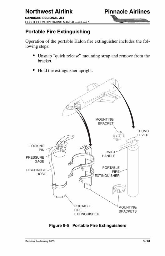
Portable Fire Extinguishing
Operation of the portable Halon fire extinguisher includes the fol-lowing steps:
● Unsnap “quick release” mounting strap and remove from thebracket.
● Hold the extinguisher upright.
MOUNTINGBRACKET
THUMBLEVER
TWISTHANDLE
PORTABLEFIRE
EXTINGUISHER
MOUNTINGBRACKETS
LOCKINGPIN
PRESSUREGAGE
DISCHARGEHOSE
PORTABLEFIREEXTINGUISHER
Figure 9-5 Portable Fire Extinguishers
Revision 1—January 2003 9-13

Northwest AirlinkCANADAIR REGIONAL JET
FLIGHT CREW OPERATING MANUAL—Volume 1
Pinnacle Airlines
● Pull the locking pin, breaking the nylon tie.
● Stand at least six feet away from the fire and aim the dis-charge hose at the base of the flame.
● Squeeze the lever and use a sweeping motion from side toside at the base of the fire.
● Move closer as the fire is being extinguished.
● Ensure the fire is completely extinguished and watch for“flashback.”
● Ventilate as promptly as possible by notifying the flight crewso that the cabin pressure can be adjusted to evacuate thesmoke through the outflow valve.
The fire extinguisher in the rear cabin compartment contains carbondioxide (CO2) in a cartridge in the twist handle at the top of the con-tainer. When the handle is turned clockwise, the cartridge ispunctured by a pin. This releases the CO2, which pressurizes thefire-extinguishing agent. The pressurized agent remains in the cylin-der until the thumb lever is pushed.
The Halon and liquid-type, Class A extinguishers operate in a verti-cal position with the locking pin pulled. The fire-extinguishingagent is properly aimed at the base of the flame from a distance ofover six feet. The lever should be squeezed and the discharge hoseswept from side to side at the base of the fire.
NOTEThe portable fire extinguishers must berecharged after use. Partial discharge maycause the bottles to leak
9-14 Revision 1—January 2003
Northwest AirlinkCANADAIR REGIONAL JET FLIGHT CREW OPERATING MANUAL—Volume 1
Pinnacle Airlines
CONTROLS AND INDICATIONS
FIRE PANEL
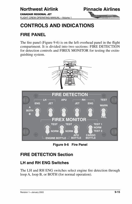
The fire panel (Figure 9-6) is on the left overhead panel in the flightcompartment. It is divided into two sections: FIRE DETECTIONfor detection controls and FIREX MONITOR for testing the extin-guishing system.
FIRE DETECTION Section
LH and RH ENG Switches
The LH and RH ENG switches select engine fire detection throughloop A, loop B, or BOTH (for normal operation).
TEST
1 2 APUBOTTLE
CARGOBOTTLEENGINE BOTTLE
NORM
TEST
NORM
TEST 1
TEST
WARNENGJET
APU
FIREX MONITOR
RHJETENG
FAIL
NORMTEST 2
ABOTH
B
FIRE DETECTIONLH
Figure 9-6 Fire Panel
Revision 1—January 2003 9-15

Northwest AirlinkCANADAIR REGIONAL JET
FLIGHT CREW OPERATING MANUAL—Volume 1
Pinnacle Airlines
LH and RH JET Switches
The LH and RH JET switches select jetpipe and pylon overheatdetection via loop A, loop B, or BOTH (for normal operation).
TEST WARN–FAIL Switch
WARN—This switch grounds the loops to simulate a fire or over-heat condition. If the test is good, the following messages appear:
● Firebell rings.
● Warning messages L and R ENG FIRE, APU FIRE, and Land R JETPIPE OVHT appear.
● “Jetpipe overheat” aural message activates.
● After 10 seconds, caution messages HYD SOV 1 or 2 OPEN,L or R ENG SOV OPEN, and APU SOV OPEN (if APU isoperating) appear.
● Switchlights LH or RH ENG FIRE PUSH, APU FIREPUSH, BOTTLE 1 and 2 ARMED PUSH TO DISCH, andAPU BOTTLE ARMED PUSH TO DISCH illuminate.
FAIL—Simulates a short on the selected loops (A or B) with the fol-lowing indications:
● Caution messages L or R FIRE FAIL, APU FIRE FAIL, andL or R JET OVHT FAIL appear.
FIREX MONITOR Section
ENGINE BOTTLE 1 and 2 Switches
TEST—Applicable Firex bottle squib circuit continuity is checked.The L or R ENG SQUIB 1 or 2 green advisory message is displayedif the test results are successful.
9-16 Revision 1—January 2003

Northwest AirlinkCANADAIR REGIONAL JET FLIGHT CREW OPERATING MANUAL—Volume 1
Pinnacle Airlines
NORM—Selects normal operation. The switches are spring-loadedto this position.
NOTEIf a CARGO BOTTLE test is conducted withthe CARGO switch selected to FAN or CONDAIR, a CARGO FAN FAIL status messagewill come on.
APU BOTTLE Switch
TEST—APU Firex bottle pressure and squib circuit continuity arechecked. The APU SQUIB 1 and 2 green advisory message is dis-played if the test results are successful.
NORM—Selects normal operation. The switches are spring-loadedto this position.
CARGO BOTTLE Switch
TEST 1—Simulates a smoke condition on the No. 1 detector withthe following indications:
● “Smoke” aural message activates.
● SMOKE CARGO warning message appears.
● CARGO SQUIB 1 advisory message appears (continuitycheck of squib 1).
● CARGO FIREX panel switchlight indications:❍ Red NORMAL CARGO SMOKE PUSH
❍ Red STANDBY CARGO SMOKE PUSH
❍ Green NORMAL BOTTLE ARMED PUSH TO DISCH
TEST 2—Simulates a smoke condition on the No. 2 detector withthe following indications:
● “Smoke” aural message activates.● SMOKE CARGO warning message appears.
Revision 1—January 2003 9-17
Northwest AirlinkCANADAIR REGIONAL JET
FLIGHT CREW OPERATING MANUAL—Volume 1
Pinnacle Airlines
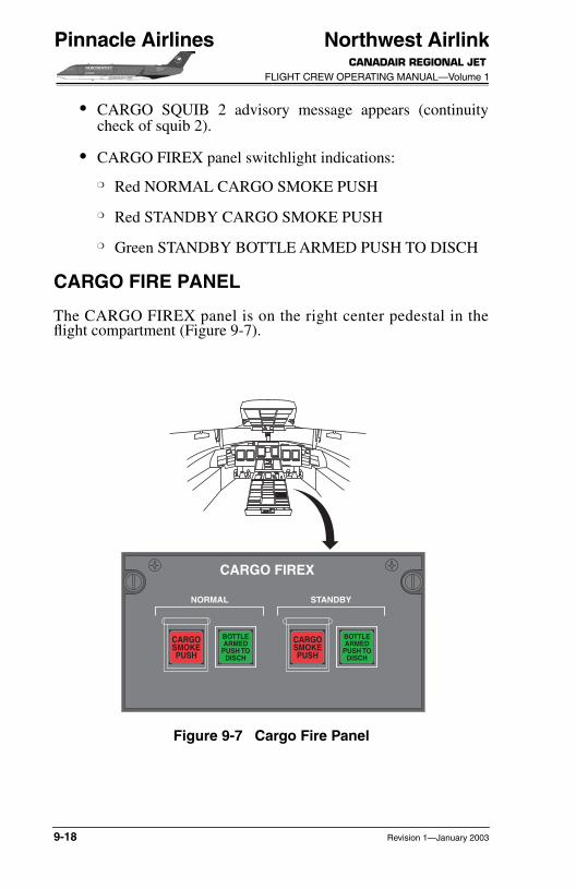
● CARGO SQUIB 2 advisory message appears (continuitycheck of squib 2).
● CARGO FIREX panel switchlight indications:
❍ Red NORMAL CARGO SMOKE PUSH
❍ Red STANDBY CARGO SMOKE PUSH
❍ Green STANDBY BOTTLE ARMED PUSH TO DISCH
CARGO FIRE PANEL
The CARGO FIREX panel is on the right center pedestal in theflight compartment (Figure 9-7).
NORMAL
CARGO FIREX
BOTTLEARMED
PUSH TODISCH
CARGOSMOKEPUSH
STANDBY
BOTTLEARMED
PUSH TODISCH
CARGOSMOKEPUSH
Figure 9-7 Cargo Fire Panel
9-18 Revision 1—January 2003

Northwest AirlinkCANADAIR REGIONAL JET FLIGHT CREW OPERATING MANUAL—Volume 1
Pinnacle Airlines
NORMAL and STANDBY CARGOSMOKE PUSH Switchlights
Both CARGO SMOKE PUSH switchlights illuminate red whensmoke is detected in the cargo compartment. The switchlights haveidentical functions and serve as backup to each other during switchmalfunction.
IN—All squibs of cargo compartment Firex bottle are armed.
OUT—All squibs of cargo compartment Firex bottle is disarmed.
NORMAL and STANDBY BOTTLE ARMED PUSH TO DISCH Switchlights
The respective BOTTLE ARMED PUSH TO DISCH switchlightilluminates green once the respective CARGO SMOKE PUSHswitchlight is pressed. This indicates the squibs are armed in bothFirex bottles.
IN—Squibs fire. Green light extinguishes once the Firex bottle isdischarged.
NOTEBOTTLE ARMED PUSH TO DISCH switch-light will extinguish when the CARGO BTLLO caution message appears. The CARGOBTL LO caution message may take up to 20minutes before it appears on EICAS, as thecargo Firex bottle gradually discharges.
Revision 3—December 2004 9-19

Northwest AirlinkCANADAIR REGIONAL JET
FLIGHT CREW OPERATING MANUAL—Volume 1
Pinnacle Airlines
LH AND RH ENG FIRE PUSH SWITCHLIGHTS
These guarded switches on the glareshield illuminate red when a fireis detected in the respective engine. These switches also illuminateduring system testing.
IN—Accomplishes the following:
● Squibs on both engine Firex bottles are armed.
● Fuel valve closes.
● Bleed-air valve closes.
● Hydraulic valve closes.
● Engine-driven generator shuts down.
OUT—All affected systems operate normally and fire alertingis armed.
GLARESHIELD
BOTTLE 1 and 2 ARMED PUSH TO DISCH Switchlights
The BOTTLE 1 and 2 ARMED PUSH TO DISCH glareshieldswitchlights illuminate green to indicate the applicable Firex bottlesquib is armed (Figure 9-8). During a test of the fire warning sys-tem, illumination of these switchlights confirms that the applicablesquib is operational.
IN—Fires the squib to discharge the applicable engine Firex bottle.
APU FIRE PUSH Switchlight
The APU FIRE PUSH switchlight on the copilot’s glareshield illu-minates red when a fire is detected in the APU compartment. Theswitch also illuminates red during APU fire testing.
9-20 Revision 1—January 2003

Northwest AirlinkCANADAIR REGIONAL JET FLIGHT CREW OPERATING MANUAL—Volume 1
Pinnacle Airlines
IN—Accomplishes the following:
● APU Firex bottle squib is armed.
● APU shutoff valve closes.
● APU is shut down.
● APU bleed-air valve closes.
OUT—The APU operates normally and fire alerting is armed.
PLTROLL
ROLL SELMASTERCAUTION STALLMASTER
WARNINGGND PROX
PULL UPBOTTLE 1
ARMEDPUSH TO
DISCH
LH ENGFIREPUSH
APUFIREPUSH
CPLTROLL
ROLL SELMASTERCAUTION
MASTERWARNING
GND PROX
PULL UPBOTTLEARMED
PUSH TODISCH
BOTTLE 2ARMED
PUSH TODISCH
RH ENGFIREPUSH
STALL
Figure 9-8 Glareshield
Revision 1—January 2003 9-21

Northwest AirlinkCANADAIR REGIONAL JET
FLIGHT CREW OPERATING MANUAL—Volume 1
Pinnacle Airlines
APU BOTTLE ARMED PUSH TO DISCH Switchlight
The BOTTLE ARMED PUSH TO DISCH switchlight on the copi-lot’s glareshield illuminates green to indicate the APU Firex bottlesquib is armed. This switchlight also illuminates during APU firetesting.
IN—Fires the squib to discharge the APU bottle.
LANDING GEAR CONTROL PANEL
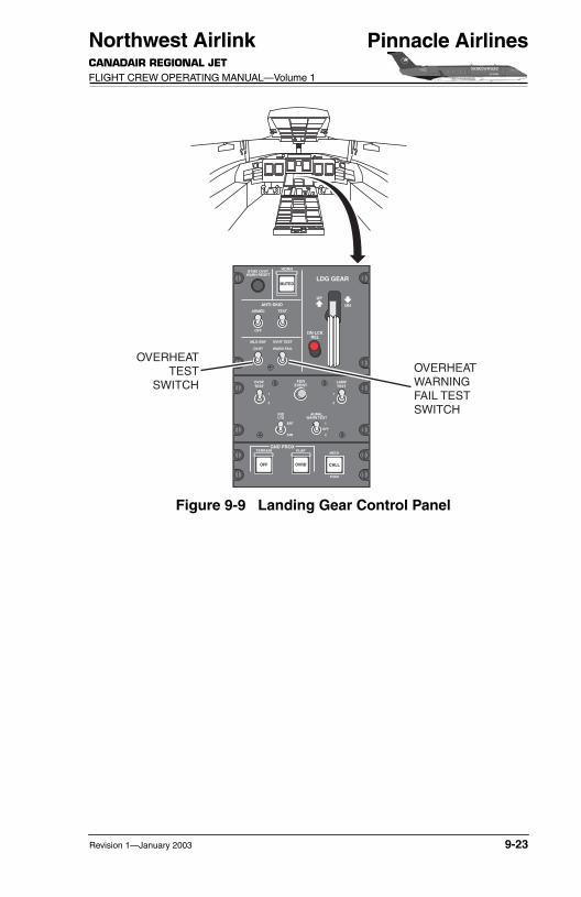
The landing gear control panel (Figure 9-9) is on the center pedestalin the flight compartment
MLG BAY OVHT Test Switch
Placing the switch in the up position simulates an overheat conditionin the main landing gear bay. An aural “gear bay overheat” warningand MLG BAY OVHT annunciation on the EICAS occur. Theswitch is spring-loaded to the normal position.
.
9-22 Revision 1—January 2003
Northwest AirlinkCANADAIR REGIONAL JET FLIGHT CREW OPERATING MANUAL—Volume 1
Pinnacle Airlines
OVERHEATWARNINGFAIL TESTSWITCH
OVERHEATTEST
SWITCH
CALL
FLAP
OVRD
TERRAIN
OFF
LDG GEARMUTED
MLG BAY
OVHT
ANTI-SKID
UP
ARMED
BTMS OVHTWARN RESET
OFF
HORN
TEST
OVHT TEST
WARN FAIL
DN
DN LCKREL
GND PROXMECH
PUSH
FDREVENT
INDLTS
DIM
BRT
LAMPTEST
2
1
OVSPTEST
2
1
AURALWARN TEST
2
OFF
1
Figure 9-9 Landing Gear Control Panel
Revision 1—January 2003 9-23
Northwest AirlinkCANADAIR REGIONAL JET
FLIGHT CREW OPERATING MANUAL—Volume 1
Pinnacle Airlines
OVHT WARN FAIL TEST Switch
Placing the switch in the up position simulates a failure in the mainlanding gear bay overheat detection system. An accompanyingMLG OVHT FAIL annunciation appears on the EICAS. The switchis spring-loaded to the normal position.
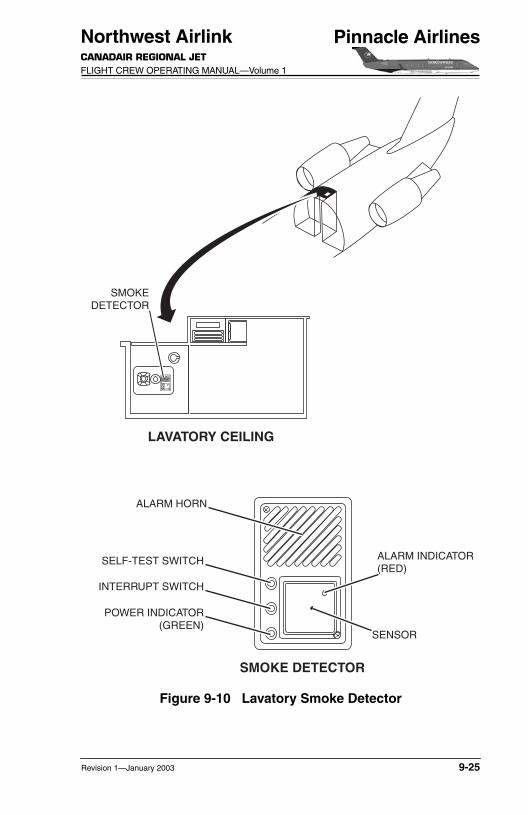
LAVATORY SMOKE DETECTOR
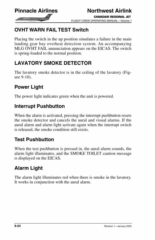
The lavatory smoke detector is in the ceiling of the lavatory (Fig-ure 9-10).
Power Light
The power light indicates green when the unit is powered.
Interrupt Pushbutton
When the alarm is activated, pressing the interrupt pushbutton resetsthe smoke detector and cancels the aural and visual alarms. If theaural alarm and alarm light activate again when the interrupt switchis released, the smoke condition still exists.
Test Pushbutton
When the test pushbutton is pressed in, the aural alarm sounds, thealarm light illuminates, and the SMOKE TOILET caution messageis displayed on the EICAS.
Alarm Light
The alarm light illuminates red when there is smoke in the lavatory.It works in conjunction with the aural alarm.
9-24 Revision 1—January 2003
Northwest AirlinkCANADAIR REGIONAL JET FLIGHT CREW OPERATING MANUAL—Volume 1
Pinnacle Airlines
SMOKEDETECTOR
LAVATORY CEILING
SMOKE DETECTOR
ALARM HORN
SELF-TEST SWITCH ALARM INDICATOR(RED)
SENSOR
INTERRUPT SWITCH
POWER INDICATOR(GREEN)
Figure 9-10 Lavatory Smoke Detector
Revision 1—January 2003 9-25
Northwest AirlinkCANADAIR REGIONAL JET
FLIGHT CREW OPERATING MANUAL—Volume 1
Pinnacle Airlines
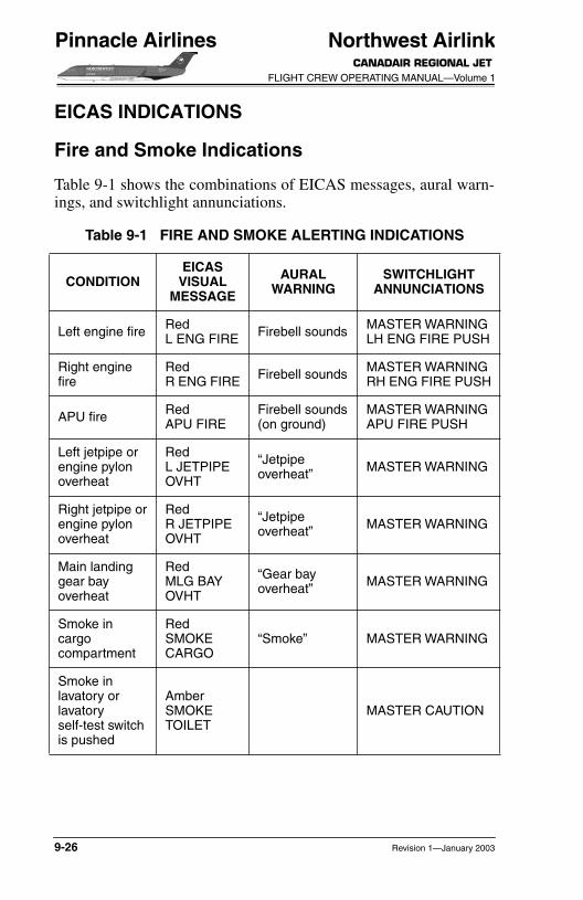
EICAS INDICATIONS
Fire and Smoke Indications
Table 9-1 shows the combinations of EICAS messages, aural warn-ings, and switchlight annunciations.
Table 9-1 FIRE AND SMOKE ALERTING INDICATIONS
CONDITIONEICAS
VISUAL MESSAGE
AURALWARNING
SWITCHLIGHTANNUNCIATIONS
Left engine fire RedL ENG FIRE Firebell sounds MASTER WARNING
LH ENG FIRE PUSH
Right engine fire
RedR ENG FIRE Firebell sounds MASTER WARNING
RH ENG FIRE PUSH
APU fire RedAPU FIRE
Firebell sounds(on ground)
MASTER WARNINGAPU FIRE PUSH
Left jetpipe orengine pylonoverheat
RedL JETPIPE OVHT
“Jetpipe overheat” MASTER WARNING
Right jetpipe orengine pylonoverheat
RedR JETPIPE OVHT
“Jetpipe overheat” MASTER WARNING
Main landing gear bay overheat
RedMLG BAY OVHT
“Gear bay overheat” MASTER WARNING
Smoke in cargo compartment
RedSMOKE CARGO
“Smoke” MASTER WARNING
Smoke in lavatory or lavatory self-test switch is pushed
AmberSMOKE TOILET
MASTER CAUTION
9-26 Revision 1—January 2003

Northwest AirlinkCANADAIR REGIONAL JET FLIGHT CREW OPERATING MANUAL—Volume 1
Pinnacle Airlines
Left engine fire-sensing loops failure
AmberL FIRE FAIL MASTER CAUTION
Right engine fire-sensing loops failure
AmberR FIRE FAIL MASTER CAUTION
APU fire-sensingloops failure
AmberAPU FIRE FAIL
MASTER CAUTION
Left jetpipe overheat sensing loops failure
AmberL JET OVHT FAIL
MASTER CAUTION
Right jetpipe overheat sensing loops failure
AmberR JET OVHT FAIL
MASTER CAUTION
Main landing gear bay sensing-loop failure
AmberMLG OVHT FAIL
MASTER CAUTION
No. 1 fire bottle low charge
AmberENG BTL 1 LO
MASTER CAUTION
No. 2 fire bottle low charge
AmberENG BTL 2 LO
MASTER CAUTION
APU fire bottle low charge
AmberAPU BTL LO
MASTER CAUTION
Cargo fire bottle low charge
AmberCARGO BTL LO
MASTER CAUTION
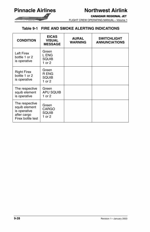
Table 9-1 FIRE AND SMOKE ALERTING INDICATIONS
CONDITIONEICAS
VISUAL MESSAGE
AURALWARNING
SWITCHLIGHTANNUNCIATIONS
Revision 1—January 2003 9-27
Northwest AirlinkCANADAIR REGIONAL JET
FLIGHT CREW OPERATING MANUAL—Volume 1
Pinnacle Airlines
Left Firex bottle 1 or 2 is operative
GreenL ENG SQUIB 1 or 2
Right Firexbottle 1 or 2is operative
GreenR ENGSQUIB1 or 2
The respective squib elementis operative
GreenAPU SQUIB1 or 2
The respective squib element is operative after cargo Firex bottle test
Green CARGO SQUIB 1 or 2
Table 9-1 FIRE AND SMOKE ALERTING INDICATIONS
CONDITIONEICAS
VISUAL MESSAGE
AURALWARNING
SWITCHLIGHTANNUNCIATIONS
9-28 Revision 1—January 2003
Northwest AirlinkCANADAIR REGIONAL JET FLIGHT CREW OPERATING MANUAL—Volume 1
Pinnacle Airlines
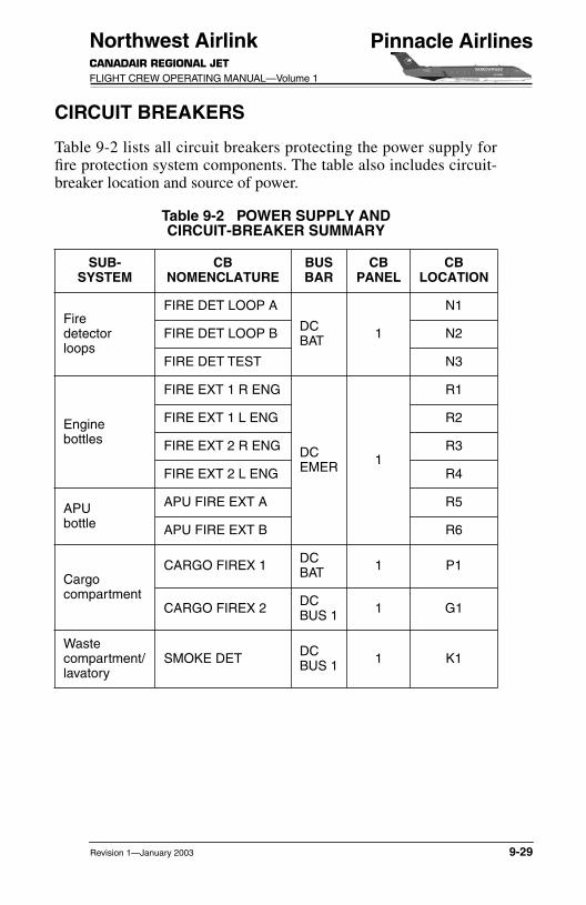
CIRCUIT BREAKERS
Table 9-2 lists all circuit breakers protecting the power supply forfire protection system components. The table also includes circuit-breaker location and source of power.
Table 9-2 POWER SUPPLY ANDCIRCUIT-BREAKER SUMMARY
SUB-SYSTEM
CBNOMENCLATURE
BUSBAR
CBPANEL
CBLOCATION
Firedetectorloops
FIRE DET LOOP A
DC BAT 1
N1
FIRE DET LOOP B N2
FIRE DET TEST N3
Enginebottles
FIRE EXT 1 R ENG
DCEMER 1
R1
FIRE EXT 1 L ENG R2
FIRE EXT 2 R ENG R3
FIRE EXT 2 L ENG R4
APUbottle
APU FIRE EXT A R5
APU FIRE EXT B R6
Cargocompartment
CARGO FIREX 1 DC BAT 1 P1
CARGO FIREX 2 DC BUS 1 1 G1
Wastecompartment/lavatory
SMOKE DET DC BUS 1 1 K1
Revision 1—January 2003 9-29

Northwest AirlinkCANADAIR REGIONAL JET
FLIGHT CREW OPERATING MANUAL—Volume 1
Pinnacle Airlines
INTENTIONALLY LEFT BLANK
9-30 Revision 1—January 2003