Embed Size (px)
Citation preview
CCNA1-1 Chapter 9-1
Chapter 9
Ethernet
Part I
CCNA1-2 Chapter 9-1
Note for Instructors
• These presentations are the result of a collaboration among
the instructors at St. Clair College in Windsor, Ontario.
• Thanks must go out to Rick Graziani of Cabrillo College. His
material and additional information was used as a reference
in their creation.
• If anyone finds any errors or omissions, please let me know
at:
CCNA1-3 Chapter 9-1
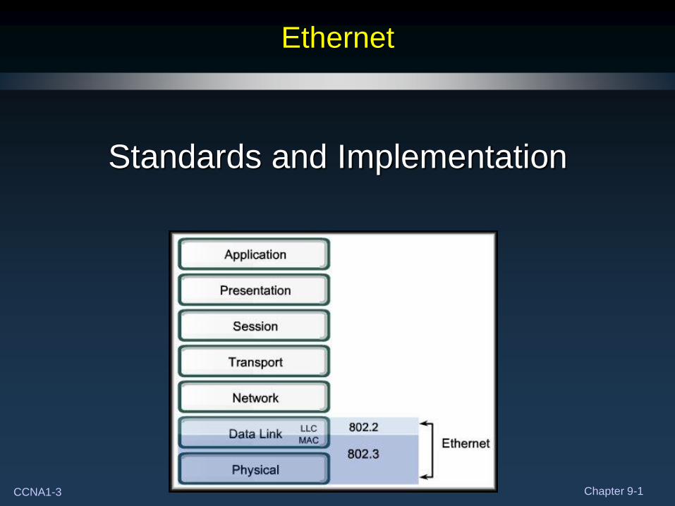
Ethernet
Standards and Implementation
CCNA1-4 Chapter 9-1
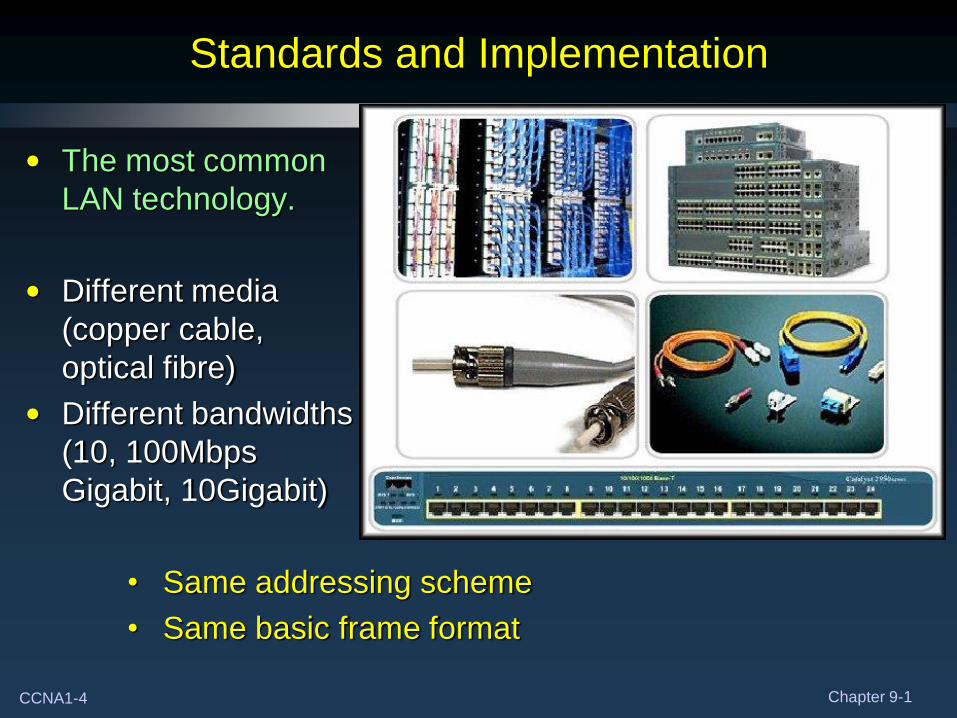
Standards and Implementation
• The most common
LAN technology.
• Different media
(copper cable,
optical fibre)
• Different bandwidths
(10, 100Mbps
Gigabit, 10Gigabit)
• Same addressing scheme
• Same basic frame format
CCNA1-5 Chapter 9-1
Standards and Implementation
• History:
• First LAN was Ethernet, designed at Xerox.
• 1980: First Ethernet standard published by DIX (Digital,
Intel, Xerox).
• 1985: IEEE modified the Ethernet standard and
published as 802.3.
CCNA1-6 Chapter 9-1
Standards and Implementation
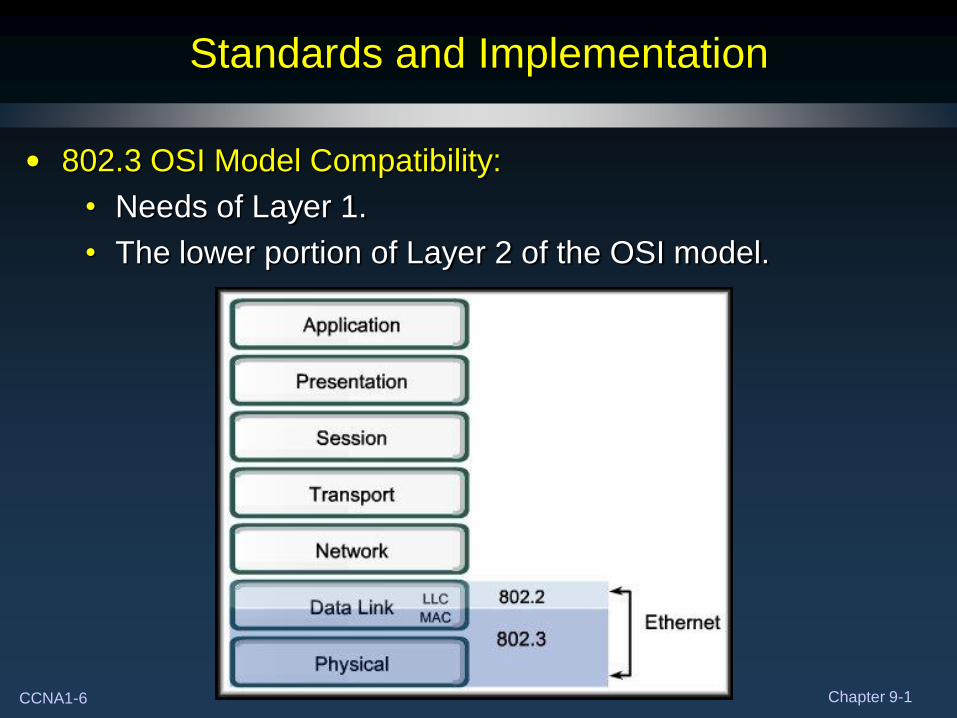
• 802.3 OSI Model Compatibility:
• Needs of Layer 1.
• The lower portion of Layer 2 of the OSI model.
CCNA1-7 Chapter 9-1
Standards and Implementation
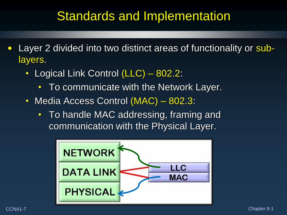
• Layer 2 divided into two distinct areas of functionality or sub-
layers.
• Logical Link Control (LLC) – 802.2:
• To communicate with the Network Layer.
• Media Access Control (MAC) – 802.3:
• To handle MAC addressing, framing and
communication with the Physical Layer.
CCNA1-8 Chapter 9-1
Standards and Implementation
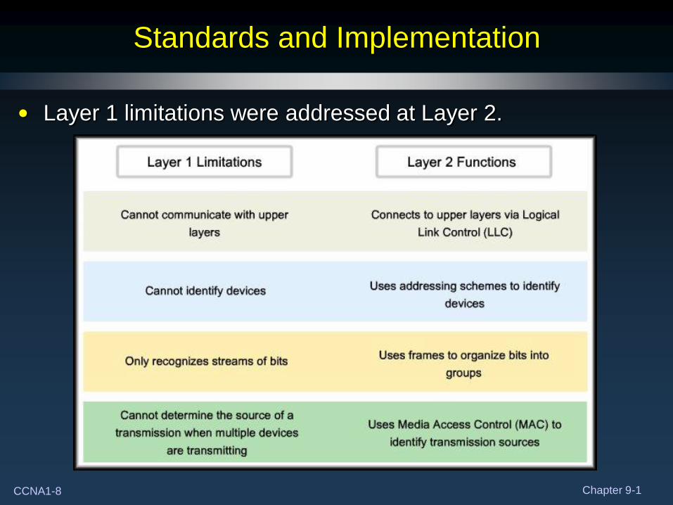
• Layer 1 limitations were addressed at Layer 2.
CCNA1-9 Chapter 9-1
Standards and Implementation
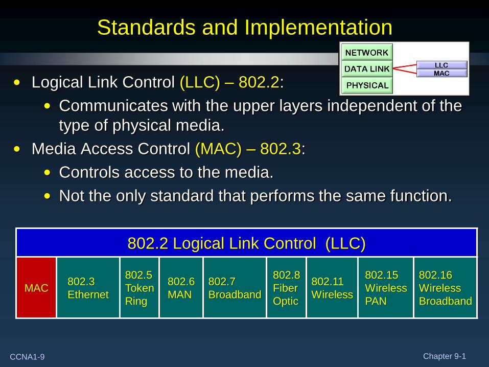
• Logical Link Control (LLC) – 802.2:
• Communicates with the upper layers independent of the
type of physical media.
• Media Access Control (MAC) – 802.3:
• Controls access to the media.
• Not the only standard that performs the same function.
802.2 Logical Link Control (LLC)
MAC 802.3
Ethernet
802.5
Token
Ring
802.6
MAN
802.7
Broadband
802.8
Fiber
Optic
802.11
Wireless
802.15
Wireless
PAN
802.16
Wireless
Broadband
CCNA1-10 Chapter 9-1
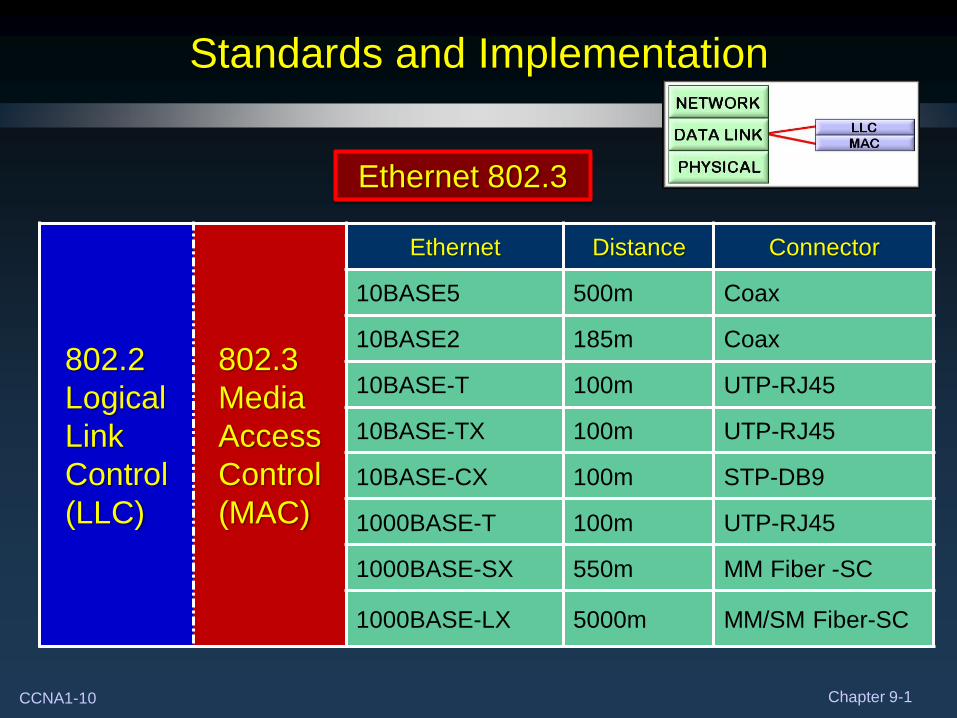
Standards and Implementation
802.2
Logical
Link
Control
(LLC)
802.3
Media
Access
Control
(MAC)
Ethernet Distance Connector
10BASE5 500m Coax
10BASE2 185m Coax
10BASE-T 100m UTP-RJ45
10BASE-TX 100m UTP-RJ45
10BASE-CX 100m STP-DB9
1000BASE-T 100m UTP-RJ45
1000BASE-SX 550m MM Fiber -SC
1000BASE-LX 5000m MM/SM Fiber-SC
Ethernet 802.3
CCNA1-11 Chapter 9-1
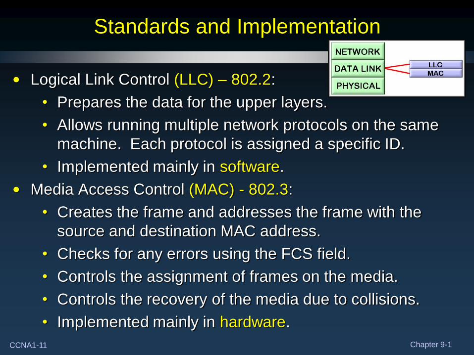
Standards and Implementation
• Logical Link Control (LLC) – 802.2:
• Prepares the data for the upper layers.
• Allows running multiple network protocols on the same
machine. Each protocol is assigned a specific ID.
• Implemented mainly in software.
• Media Access Control (MAC) - 802.3:
• Creates the frame and addresses the frame with the
source and destination MAC address.
• Checks for any errors using the FCS field.
• Controls the assignment of frames on the media.
• Controls the recovery of the media due to collisions.
• Implemented mainly in hardware.
CCNA1-12 Chapter 9-1
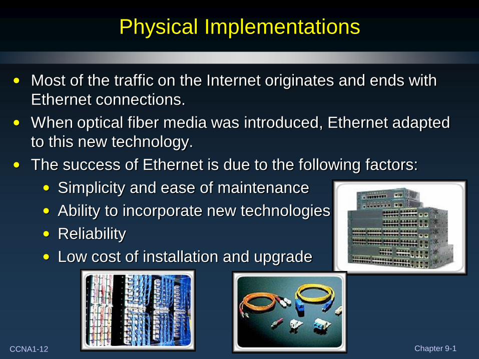
Physical Implementations
• Most of the traffic on the Internet originates and ends with
Ethernet connections.
• When optical fiber media was introduced, Ethernet adapted
to this new technology.
• The success of Ethernet is due to the following factors:
• Simplicity and ease of maintenance
• Ability to incorporate new technologies
• Reliability
• Low cost of installation and upgrade
CCNA1-13 Chapter 9-1
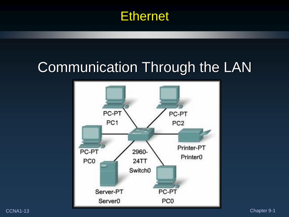
Ethernet
Communication Through the LAN
CCNA1-14 Chapter 9-1
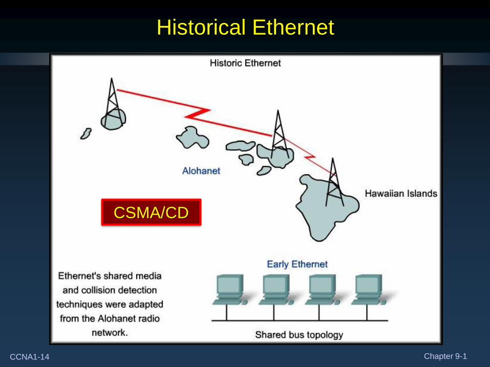
Historical Ethernet
CSMA/CD
CCNA1-15 Chapter 9-1
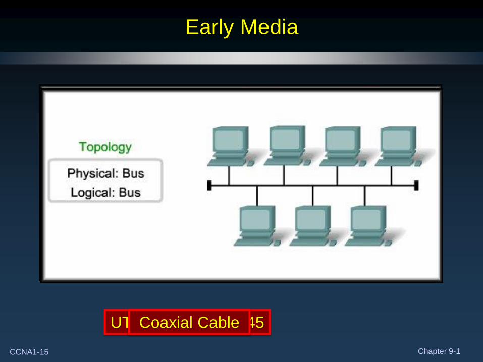
UTP Cable with RJ45 Coaxial Cable
Early Media
CCNA1-16 Chapter 9-1
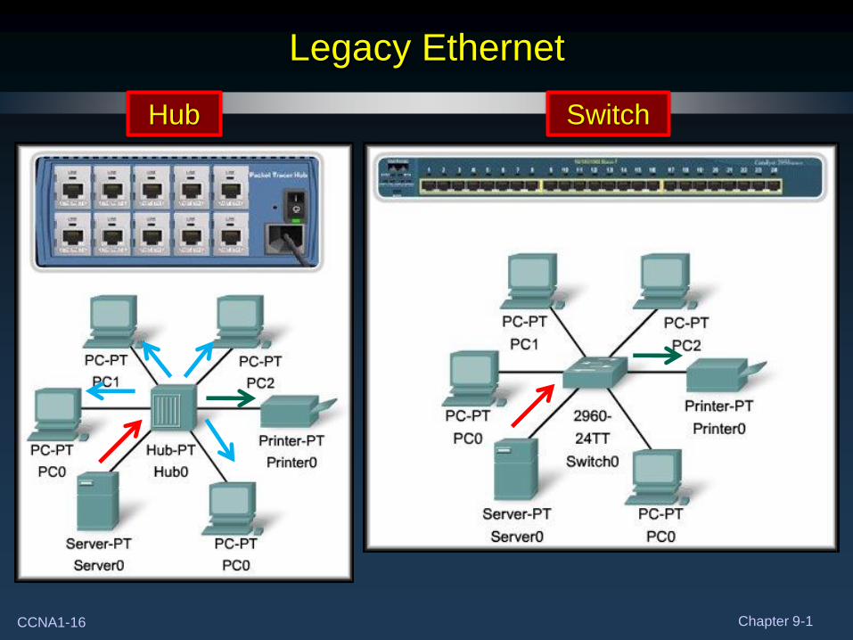
Legacy Ethernet
Hub Switch
CCNA1-17 Chapter 9-1
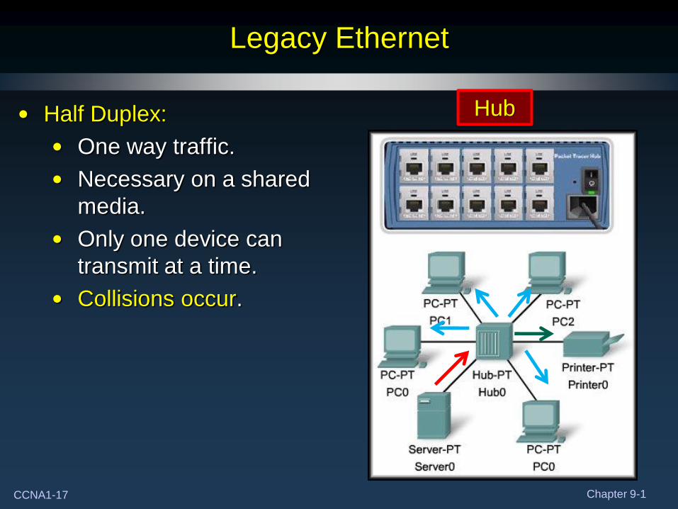
Legacy Ethernet
Hub • Half Duplex:
• One way traffic.
• Necessary on a shared
media.
• Only one device can
transmit at a time.
• Collisions occur.
CCNA1-18 Chapter 9-1
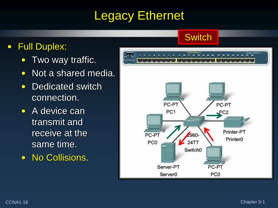
Switch
Legacy Ethernet
• Full Duplex:
• Two way traffic.
• Not a shared media.
• Dedicated switch
connection.
• A device can
transmit and
receive at the
same time.
• No Collisions.
CCNA1-19 Chapter 9-1
Legacy Ethernet
• Ethernet with hubs is designed to work with collisions.
• Collisions occur when devices transmit at the same time.
• Managed by CSMA/CD.
• As more devices are added, more collisions occur.
• As more collisions occur, network performance degrades.
• Half Duplex communication.
• Ethernet with switches is designed to eliminate collisions.
• Each device attached to switch only receives frames
destined for that device.
• Full Duplex communication.
CCNA1-20 Chapter 9-1
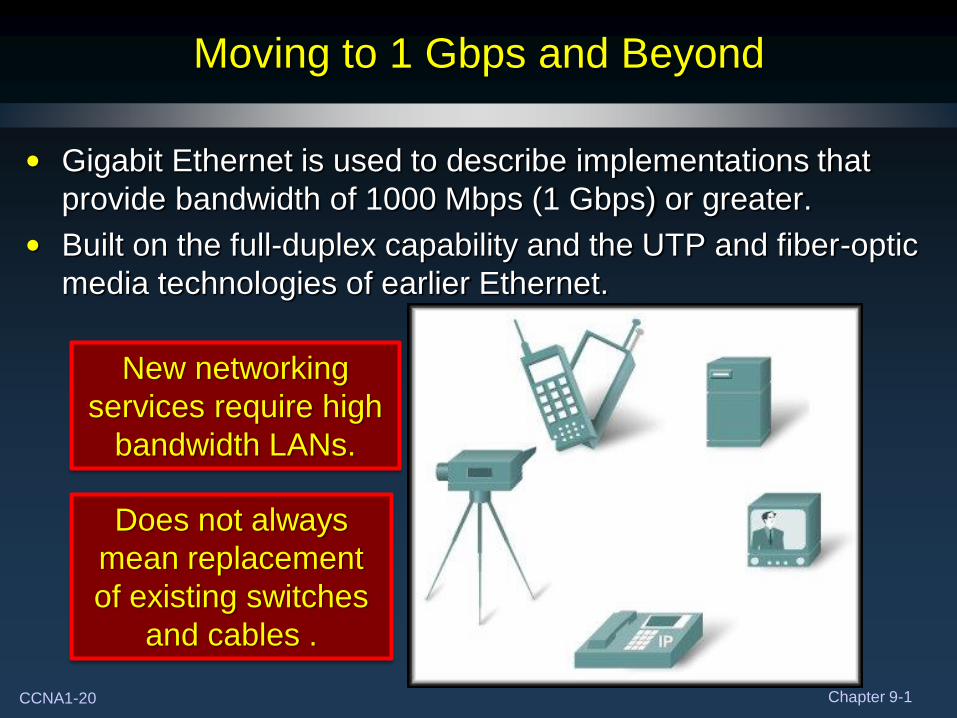
Moving to 1 Gbps and Beyond
• Gigabit Ethernet is used to describe implementations that
provide bandwidth of 1000 Mbps (1 Gbps) or greater.
• Built on the full-duplex capability and the UTP and fiber-optic
media technologies of earlier Ethernet.
New networking
services require high
bandwidth LANs.
Does not always
mean replacement
of existing switches
and cables .
CCNA1-21 Chapter 9-1
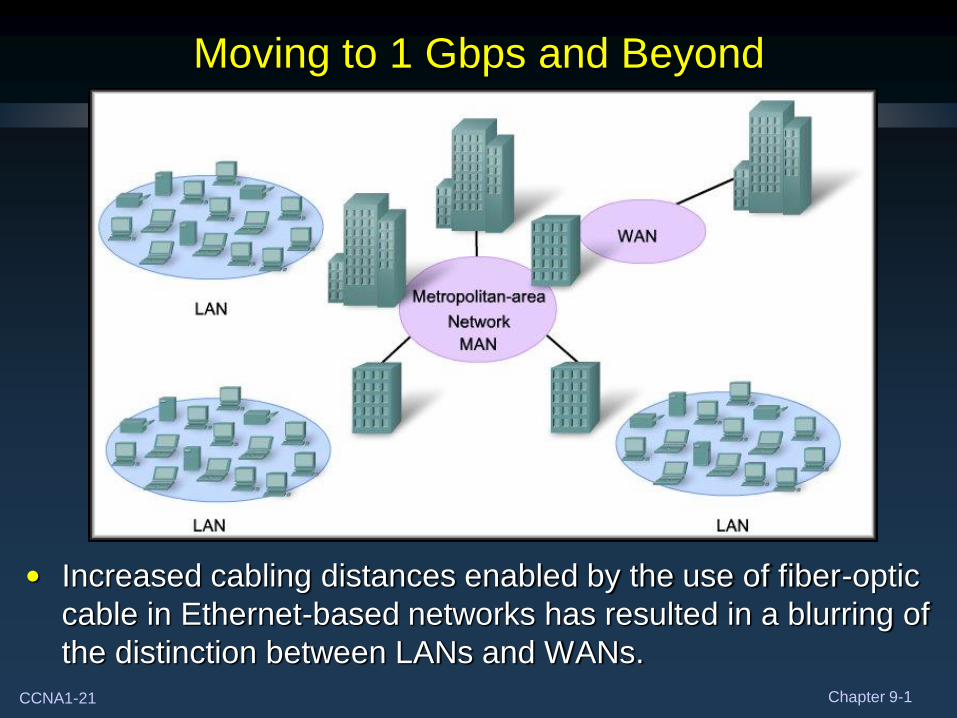
Moving to 1 Gbps and Beyond
• Increased cabling distances enabled by the use of fiber-optic
cable in Ethernet-based networks has resulted in a blurring of
the distinction between LANs and WANs.
CCNA1-22 Chapter 9-1
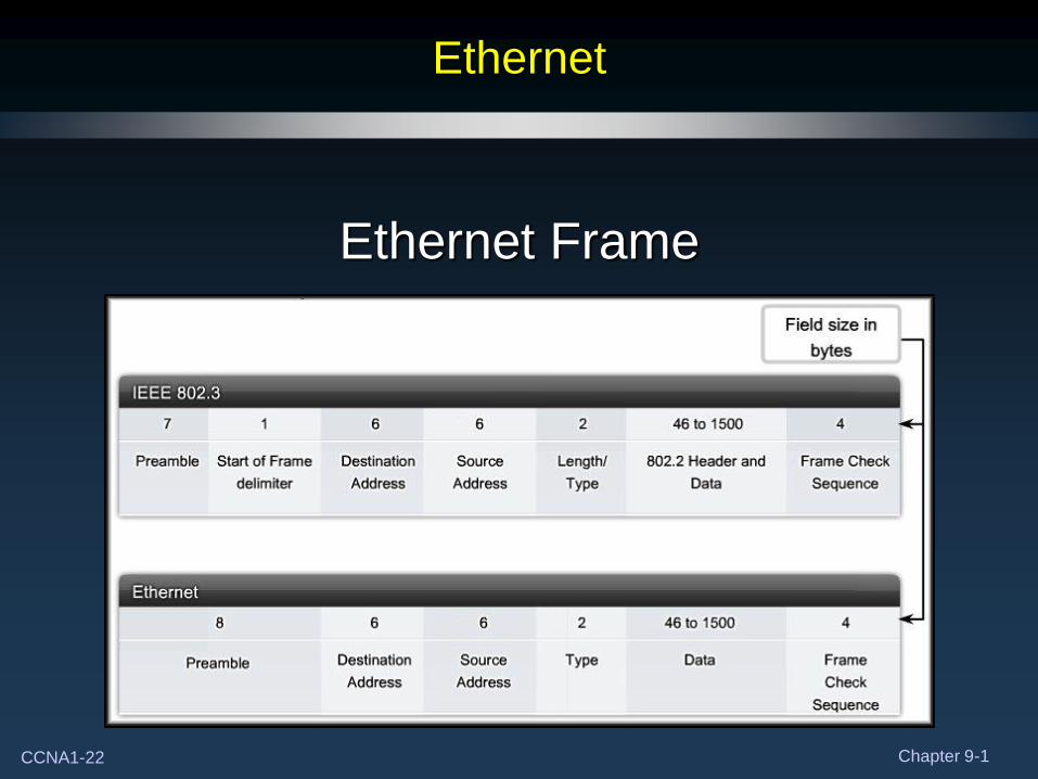
Ethernet
Ethernet Frame
CCNA1-23 Chapter 9-1
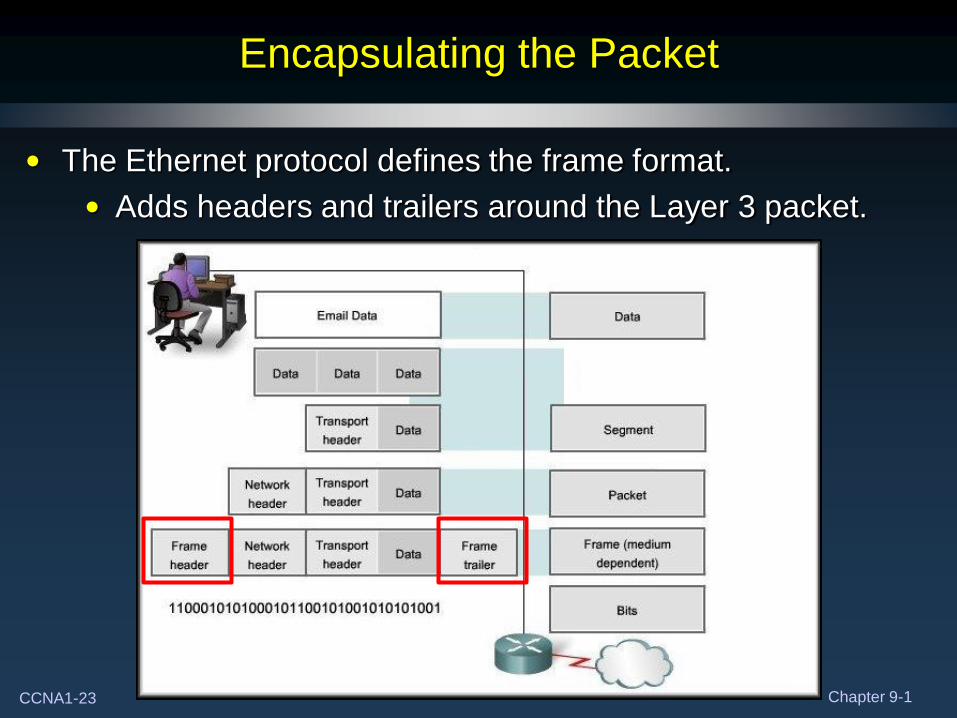
Encapsulating the Packet
• The Ethernet protocol defines the frame format.
• Adds headers and trailers around the Layer 3 packet.
CCNA1-24 Chapter 9-1
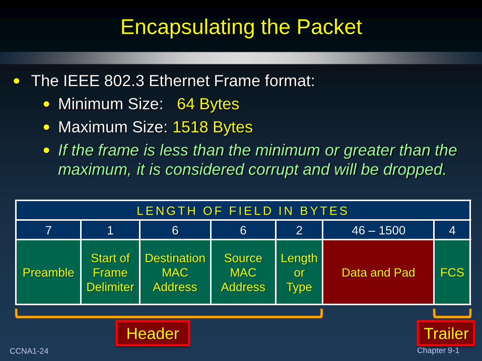
Encapsulating the Packet
• The IEEE 802.3 Ethernet Frame format:
• Minimum Size: 64 Bytes
• Maximum Size: 1518 Bytes
• If the frame is less than the minimum or greater than the
maximum, it is considered corrupt and will be dropped.
L E N G T H O F F I E L D I N B Y T E S
7 1 6 6 2 46 – 1500 4
Preamble
Start of
Frame
Delimiter
Destination
MAC
Address
Source
MAC
Address
Length
or
Type
Data and Pad FCS
Header Trailer
CCNA1-25 Chapter 9-1
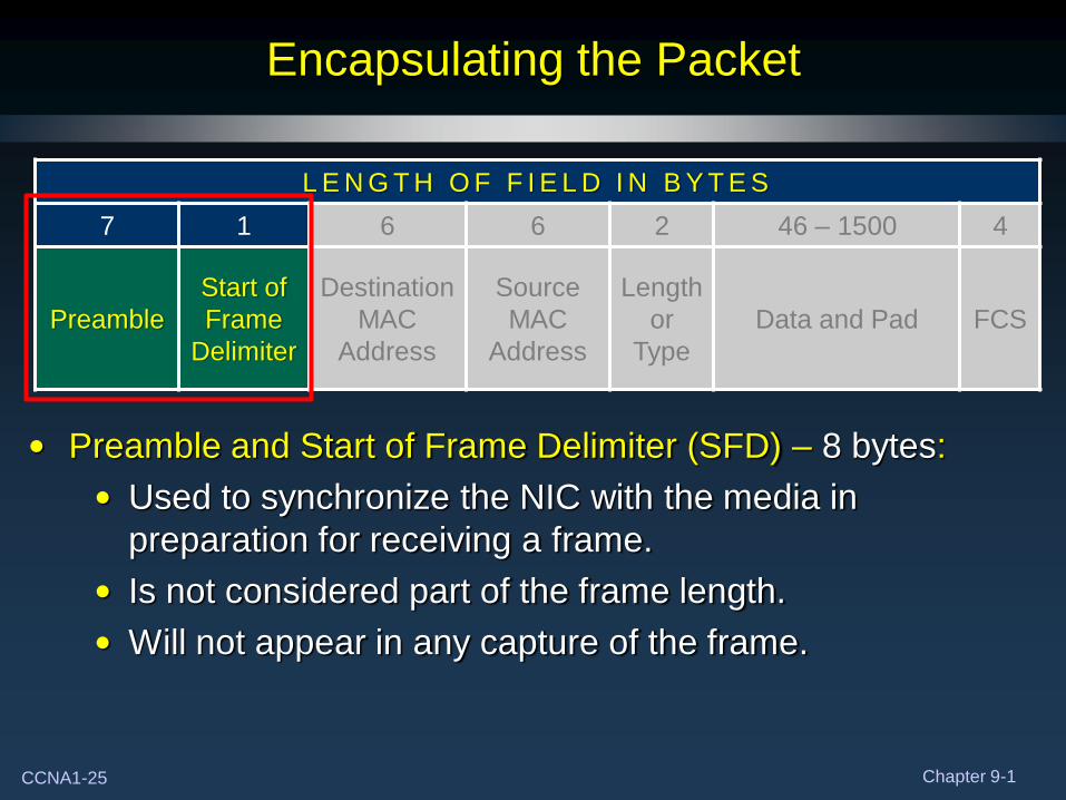
Encapsulating the Packet
• Preamble and Start of Frame Delimiter (SFD) – 8 bytes:
• Used to synchronize the NIC with the media in
preparation for receiving a frame.
• Is not considered part of the frame length.
• Will not appear in any capture of the frame.
L E N G T H O F F I E L D I N B Y T E S
7 1 6 6 2 46 – 1500 4
Preamble
Start of
Frame
Delimiter
Destination
MAC
Address
Source
MAC
Address
Length
or
Type
Data and Pad FCS
CCNA1-26 Chapter 9-1
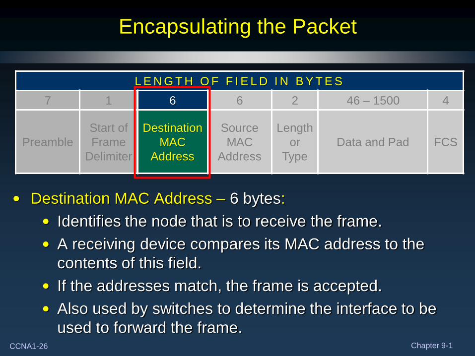
Encapsulating the Packet
• Destination MAC Address – 6 bytes:
• Identifies the node that is to receive the frame.
• A receiving device compares its MAC address to the
contents of this field.
• If the addresses match, the frame is accepted.
• Also used by switches to determine the interface to be
used to forward the frame.
L E N G T H O F F I E L D I N B Y T E S
7 1 6 6 2 46 – 1500 4
Preamble
Start of
Frame
Delimiter
Destination
MAC
Address
Source
MAC
Address
Length
or
Type
Data and Pad FCS
CCNA1-27 Chapter 9-1
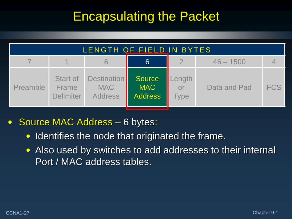
Encapsulating the Packet
• Source MAC Address – 6 bytes:
• Identifies the node that originated the frame.
• Also used by switches to add addresses to their internal
Port / MAC address tables.
L E N G T H O F F I E L D I N B Y T E S
7 1 6 6 2 46 – 1500 4
Preamble
Start of
Frame
Delimiter
Destination
MAC
Address
Source
MAC
Address
Length
or
Type
Data and Pad FCS
CCNA1-28 Chapter 9-1
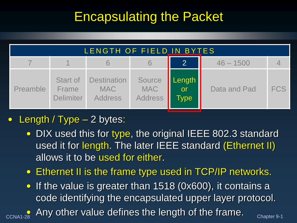
Encapsulating the Packet
• Length / Type – 2 bytes:
• DIX used this for type, the original IEEE 802.3 standard
used it for length. The later IEEE standard (Ethernet II)
allows it to be used for either.
• Ethernet II is the frame type used in TCP/IP networks.
• If the value is greater than 1518 (0x600), it contains a
code identifying the encapsulated upper layer protocol.
• Any other value defines the length of the frame.
L E N G T H O F F I E L D I N B Y T E S
7 1 6 6 2 46 – 1500 4
Preamble
Start of
Frame
Delimiter
Destination
MAC
Address
Source
MAC
Address
Length
or
Type
Data and Pad FCS
CCNA1-29 Chapter 9-1
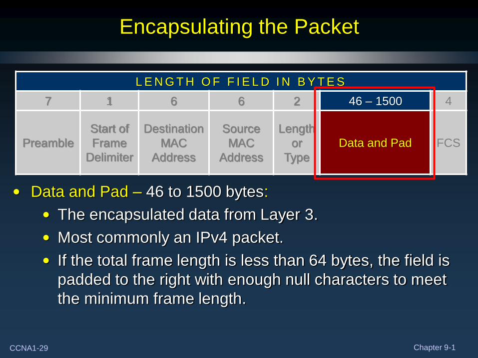
Encapsulating the Packet
• Data and Pad – 46 to 1500 bytes:
• The encapsulated data from Layer 3.
• Most commonly an IPv4 packet.
• If the total frame length is less than 64 bytes, the field is
padded to the right with enough null characters to meet
the minimum frame length.
L E N G T H O F F I E L D I N B Y T E S
7 1 6 6 2 46 – 1500 4
Preamble
Start of
Frame
Delimiter
Destination
MAC
Address
Source
MAC
Address
Length
or
Type
Data and Pad FCS
CCNA1-30 Chapter 9-1
Encapsulating the Packet
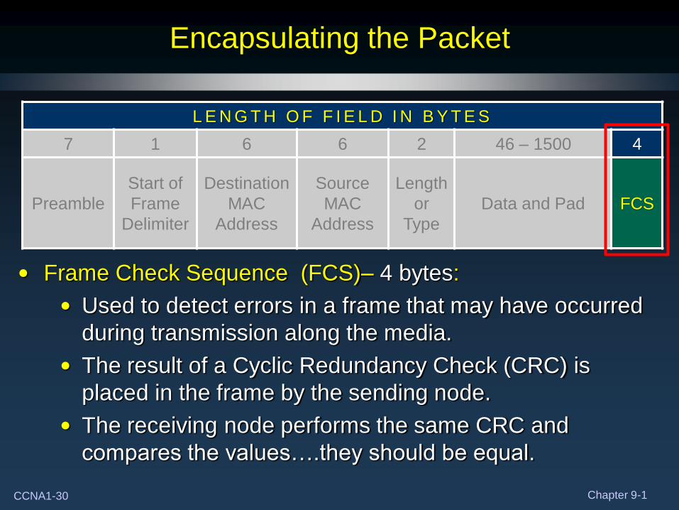
• Frame Check Sequence (FCS)– 4 bytes:
• Used to detect errors in a frame that may have occurred
during transmission along the media.
• The result of a Cyclic Redundancy Check (CRC) is
placed in the frame by the sending node.
• The receiving node performs the same CRC and
compares the values….they should be equal.
L E N G T H O F F I E L D I N B Y T E S
7 1 6 6 2 46 – 1500 4
Preamble
Start of
Frame
Delimiter
Destination
MAC
Address
Source
MAC
Address
Length
or
Type
Data and Pad FCS
CCNA1-31 Chapter 9-1
Ethernet MAC Address
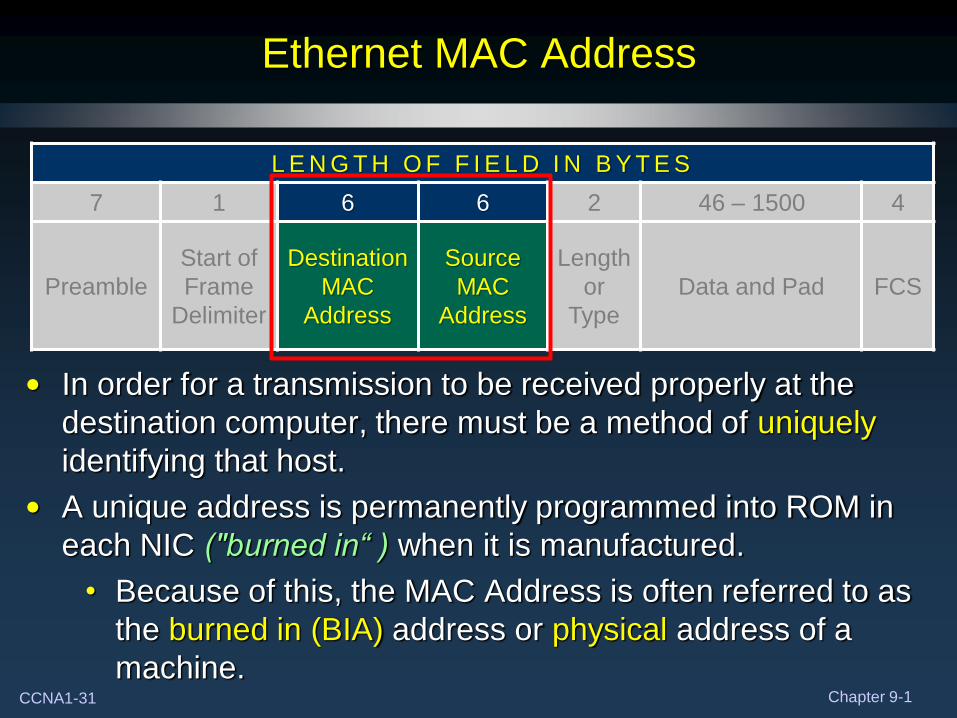
• In order for a transmission to be received properly at the
destination computer, there must be a method of uniquely
identifying that host.
• A unique address is permanently programmed into ROM in
each NIC ("burned in“ ) when it is manufactured.
• Because of this, the MAC Address is often referred to as
the burned in (BIA) address or physical address of a
machine.
L E N G T H O F F I E L D I N B Y T E S
7 1 6 6 2 46 – 1500 4
Preamble
Start of
Frame
Delimiter
Destination
MAC
Address
Source
MAC
Address
Length
or
Type
Data and Pad FCS
CCNA1-32 Chapter 9-1
Ethernet MAC Address
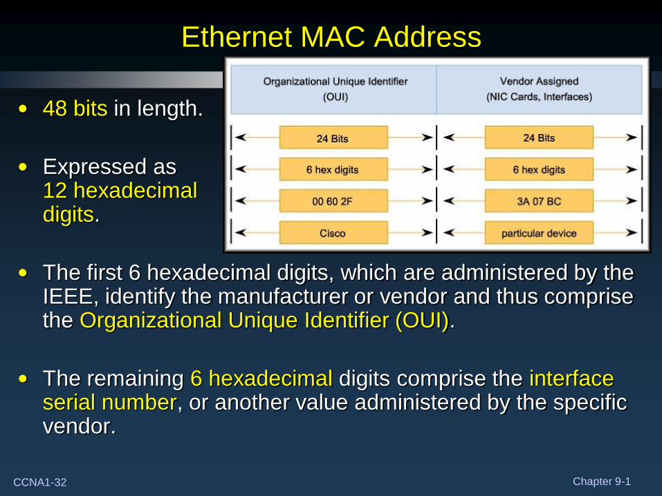
• 48 bits in length.
• Expressed as 12 hexadecimal digits.
• The first 6 hexadecimal digits, which are administered by the IEEE, identify the manufacturer or vendor and thus comprise the Organizational Unique Identifier (OUI).
• The remaining 6 hexadecimal digits comprise the interface serial number, or another value administered by the specific vendor.
CCNA1-33 Chapter 9-1
Ethernet MAC Address
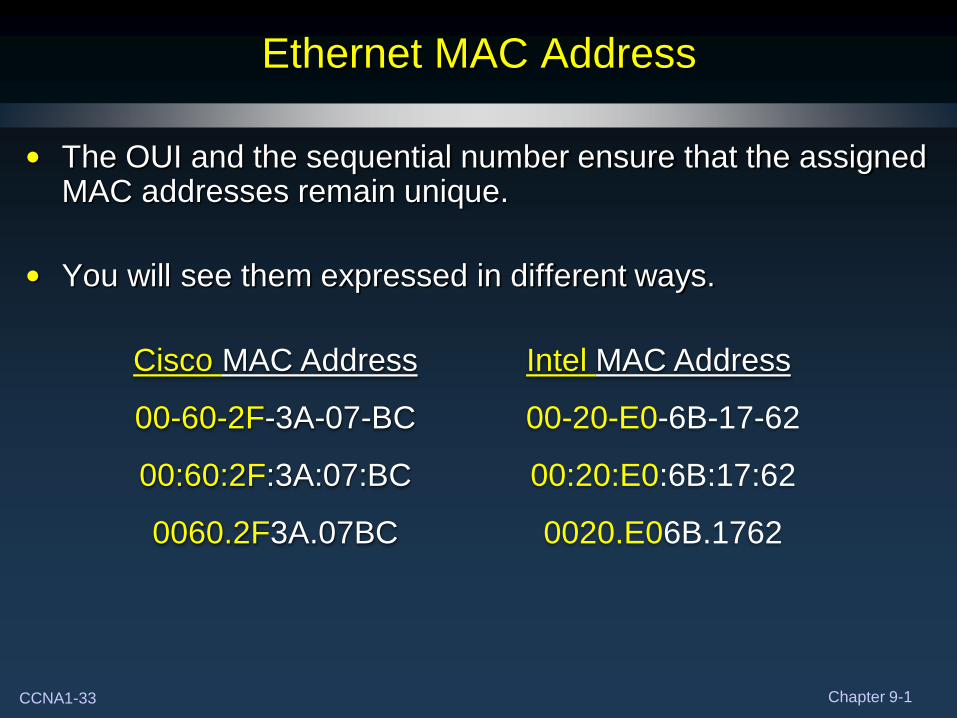
• The OUI and the sequential number ensure that the assigned MAC addresses remain unique.
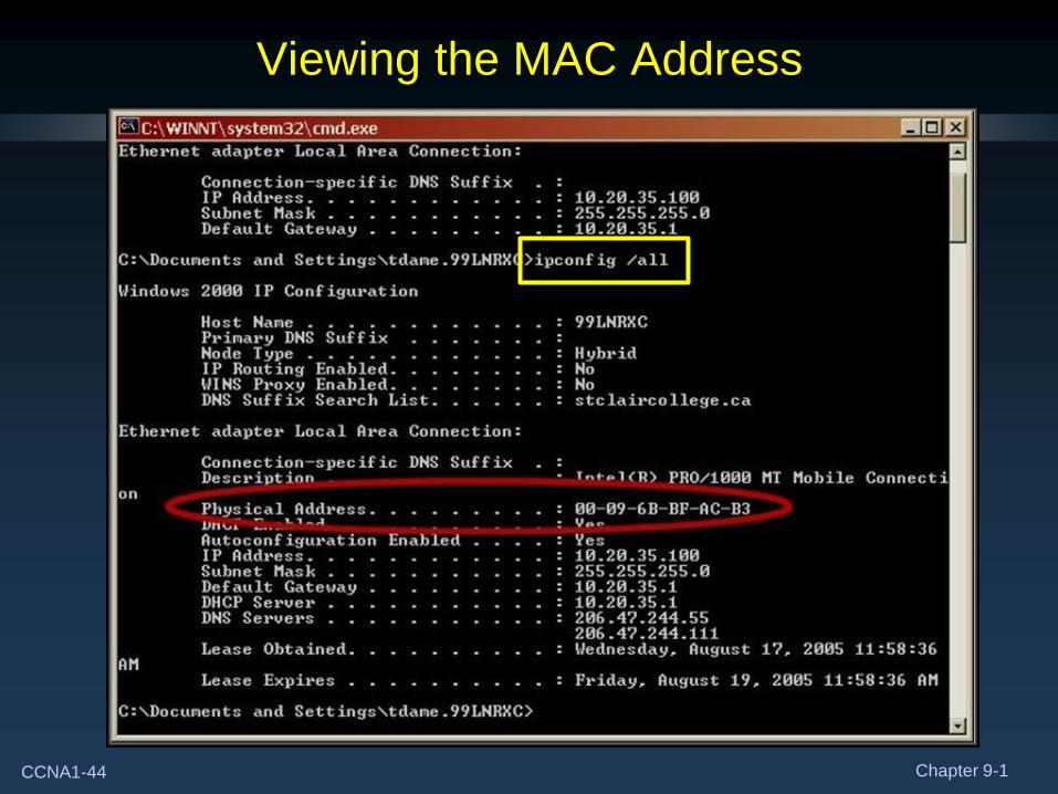
• You will see them expressed in different ways.
Cisco MAC Address
00-60-2F-3A-07-BC
00:60:2F:3A:07:BC
0060.2F3A.07BC
Intel MAC Address
00-20-E0-6B-17-62
00:20:E0:6B:17:62
0020.E06B.1762
CCNA1-34 Chapter 9-1
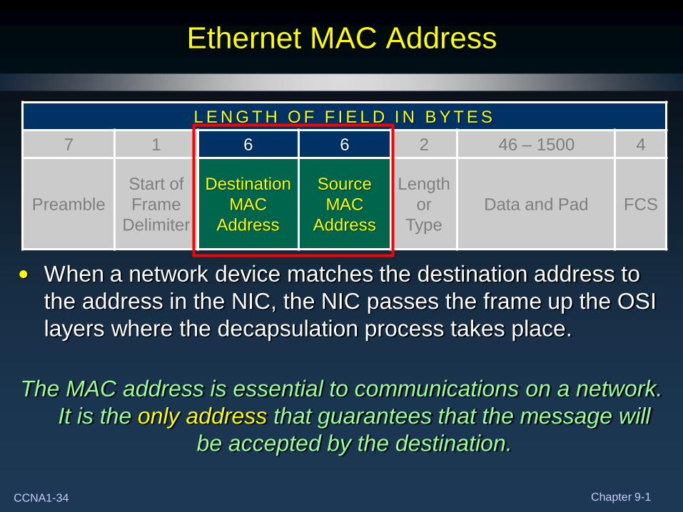
Ethernet MAC Address
• When a network device matches the destination address to
the address in the NIC, the NIC passes the frame up the OSI
layers where the decapsulation process takes place.
The MAC address is essential to communications on a network.
It is the only address that guarantees that the message will
be accepted by the destination.
L E N G T H O F F I E L D I N B Y T E S
7 1 6 6 2 46 – 1500 4
Preamble
Start of
Frame
Delimiter
Destination
MAC
Address
Source
MAC
Address
Length
or
Type
Data and Pad FCS
CCNA1-35 Chapter 9-1
Hexadecimal Numbering and Addressing
• A big problem with the binary system was verbosity. In order
to represent the number 202:
• Requires 3 decimal digits (202).
• Requires 8 bits (11001010).
• When representing large numbers, the binary system quickly
becomes unwieldy.
• We can also convert from decimal to binary but the
conversion is not a trivial task.
CCNA1-36 Chapter 9-1
Hexadecimal Numbering and Addressing
• The hexadecimal numbering system addresses both of these
issues:
• It is compact.
• It easy to convert from binary to hexadecimal and vice
versa.
• Because of this most of the computers in use today use
the hexadecimal system.
CCNA1-37 Chapter 9-1
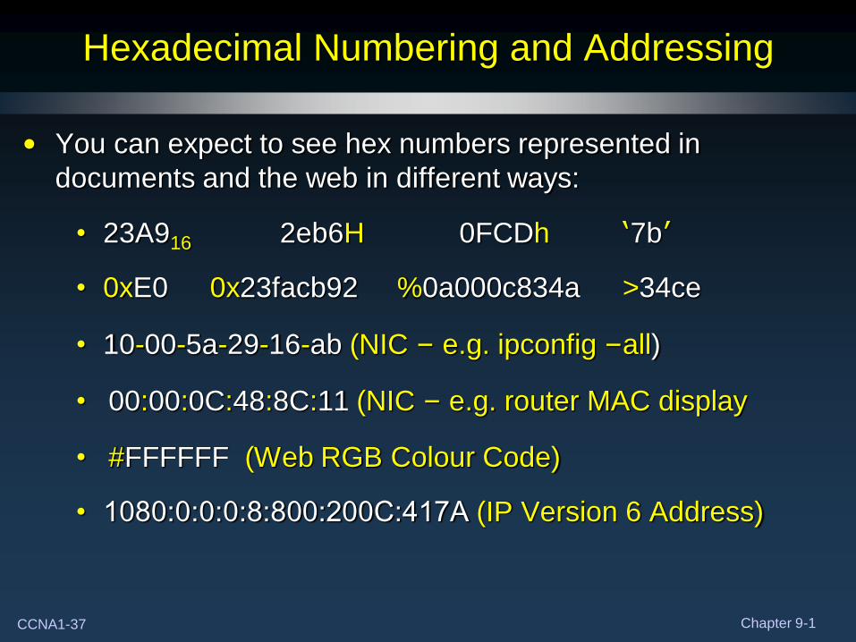
Hexadecimal Numbering and Addressing
• You can expect to see hex numbers represented in
documents and the web in different ways:
• 23A916 2eb6H 0FCDh ‘7b’
• 0xE0 0x23facb92 %0a000c834a >34ce
• 10-00-5a-29-16-ab (NIC – e.g. ipconfig –all)
• 00:00:0C:48:8C:11 (NIC – e.g. router MAC display
• #FFFFFF (Web RGB Colour Code)
• 1080:0:0:0:8:800:200C:417A (IP Version 6 Address)
CCNA1-38 Chapter 9-1
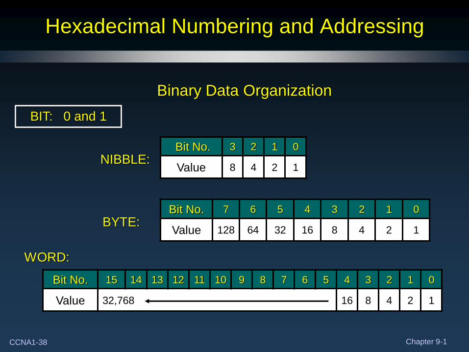
Hexadecimal Numbering and Addressing
Bit No. 3 2 1 0
Value 8 4 2 1
Bit No. 7 6 5 4 3 2 1 0
Value 128 64 32 16 8 4 2 1
BIT: 0 and 1
NIBBLE:
BYTE:
WORD:
Bit No. 15 14 13 12 11 10 9 8 7 6 5 4 3 2 1 0
Value 32,768 16 8 4 2 1
Binary Data Organization
CCNA1-39 Chapter 9-1
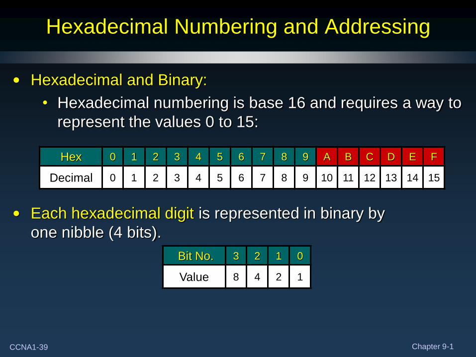
Hexadecimal Numbering and Addressing
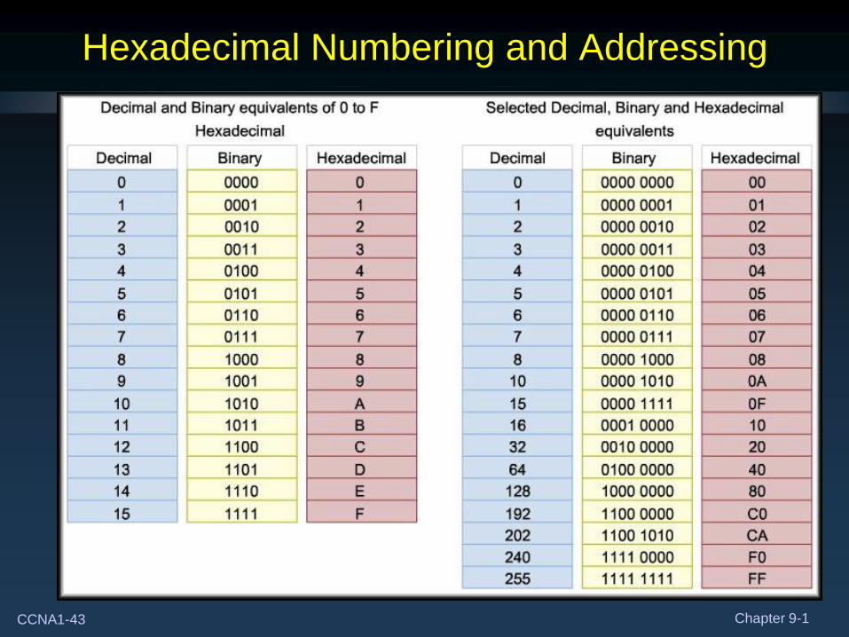
• Hexadecimal and Binary:
• Hexadecimal numbering is base 16 and requires a way to
represent the values 0 to 15:
• Each hexadecimal digit is represented in binary by
one nibble (4 bits).
Hex 0 1 2 3 4 5 6 7 8 9 A B C D E F
Decimal 0 1 2 3 4 5 6 7 8 9 10 11 12 13 14 15
Bit No. 3 2 1 0
Value 8 4 2 1
CCNA1-40 Chapter 9-1
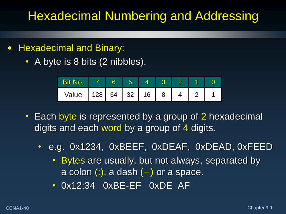
Hexadecimal Numbering and Addressing
• Hexadecimal and Binary:
• A byte is 8 bits (2 nibbles).
• Each byte is represented by a group of 2 hexadecimal
digits and each word by a group of 4 digits.
• e.g. 0x1234, 0xBEEF, 0xDEAF, 0xDEAD, 0xFEED
• Bytes are usually, but not always, separated by
a colon (:), a dash (–) or a space.
• 0x12:34 0xBE-EF 0xDE AF
Bit No. 7 6 5 4 3 2 1 0
Value 128 64 32 16 8 4 2 1
CCNA1-41 Chapter 9-1
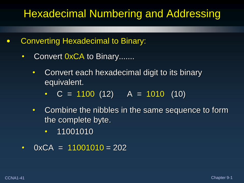
Hexadecimal Numbering and Addressing
• Converting Hexadecimal to Binary:
• Convert 0xCA to Binary…….
• Convert each hexadecimal digit to its binary
equivalent.
• C = 1100 (12) A = 1010 (10)
• Combine the nibbles in the same sequence to form
the complete byte.
• 11001010
• 0xCA = 11001010 = 202
CCNA1-42 Chapter 9-1
Hexadecimal Numbering and Addressing
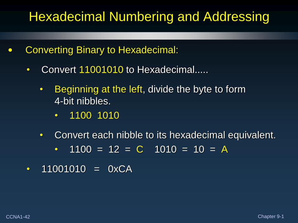
• Converting Binary to Hexadecimal:
• Convert 11001010 to Hexadecimal…..
• Beginning at the left, divide the byte to form
4-bit nibbles.
• 1100 1010
• Convert each nibble to its hexadecimal equivalent.
• 1100 = 12 = C 1010 = 10 = A
• 11001010 = 0xCA
CCNA1-43 Chapter 9-1
Hexadecimal Numbering and Addressing
CCNA1-44 Chapter 9-1
Viewing the MAC Address
CCNA1-45 Chapter 9-1
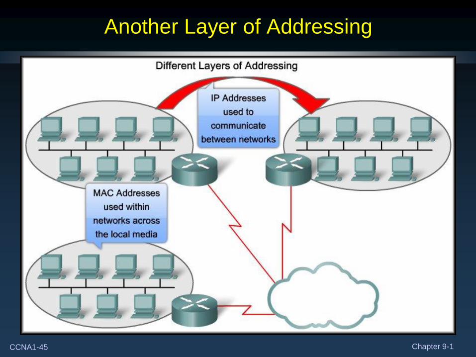
Another Layer of Addressing
CCNA1-46 Chapter 9-1
Ethernet Unicast, Multicast and Broadcast
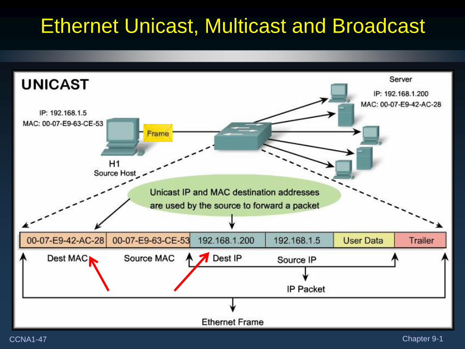
• Different MAC addresses are used to provide different types
of communication.
• Unicast:
• A unique address identifying a specific host.
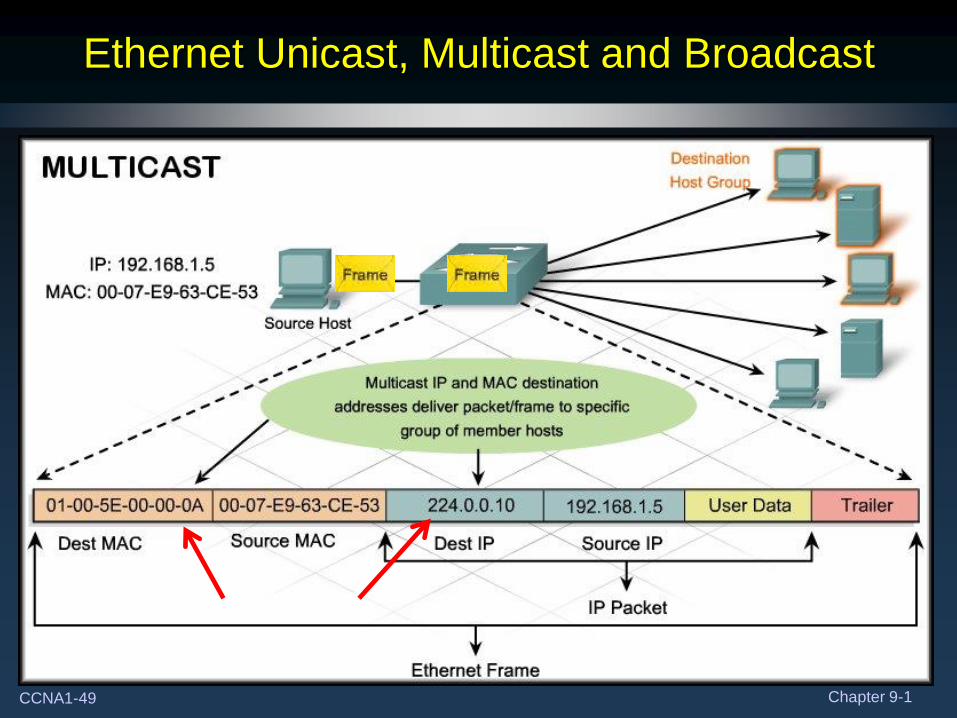
• Multicast:
• An address recognized by a specific group of hosts.
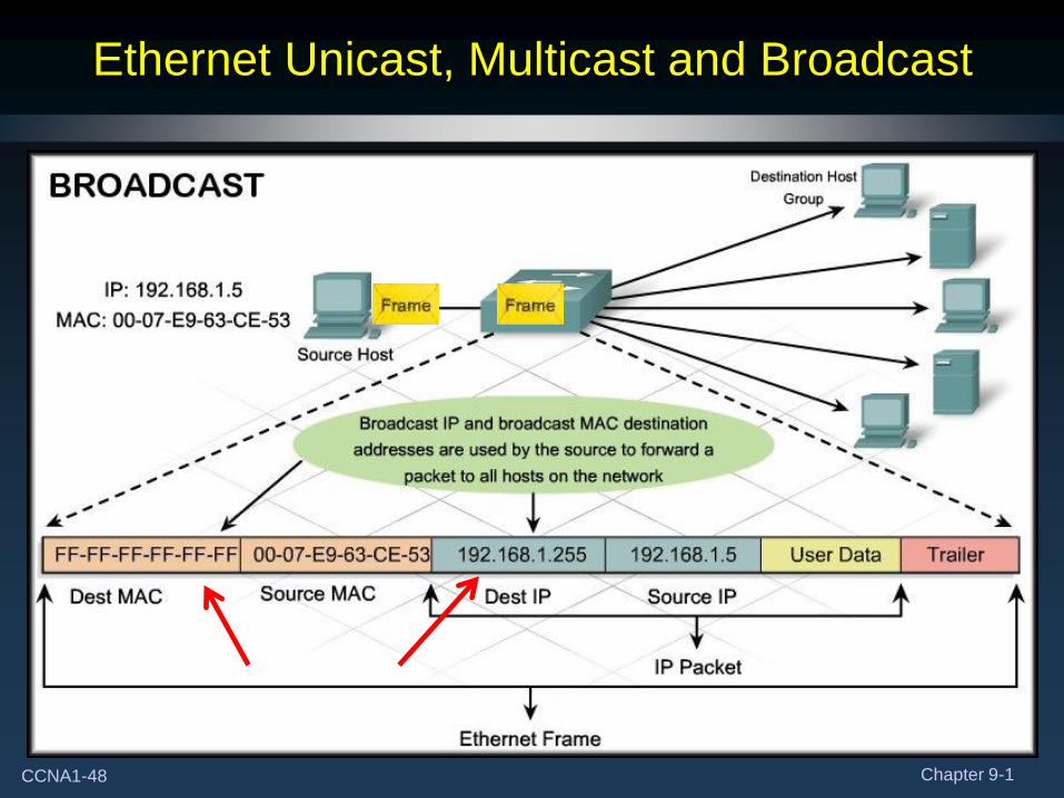
• Broadcast:
• An address used to send information to all hosts.
CCNA1-47 Chapter 9-1
Ethernet Unicast, Multicast and Broadcast
CCNA1-48 Chapter 9-1
Ethernet Unicast, Multicast and Broadcast
CCNA1-49 Chapter 9-1
Ethernet Unicast, Multicast and Broadcast
CCNA1-50 Chapter 9-1
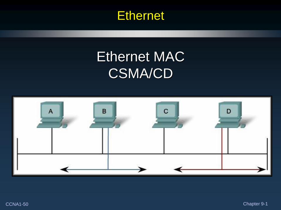
Ethernet
Ethernet MAC
CSMA/CD
CCNA1-51 Chapter 9-1
Ethernet MAC method
• In a shared media environment, all devices have guaranteed
access to the medium but they have no prioritized claim on it.
• If more than one device transmits simultaneously
• The physical signals collide.
• The network must recover.
• Collisions are the cost that Ethernet pays to get the low
overhead associated with each transmission.
• Ethernet uses Carrier Sense Multiple Access with Collision
Detection (CSMA/CD) to detect and handle collisions and
manage the resumption of communications.
CCNA1-52 Chapter 9-1
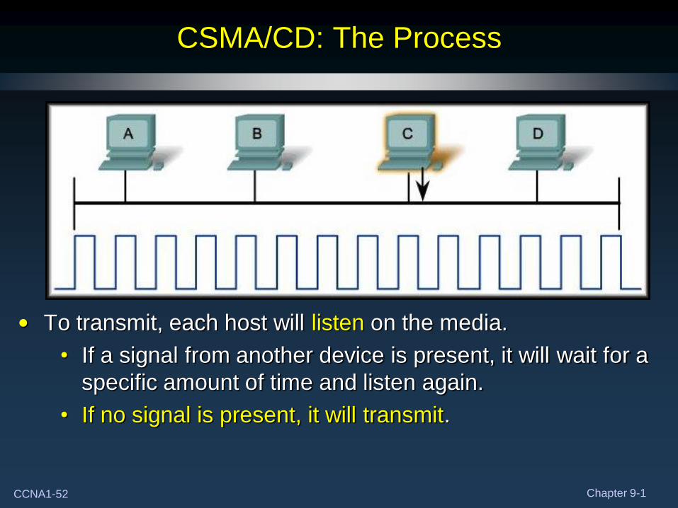
CSMA/CD: The Process
• To transmit, each host will listen on the media.
• If a signal from another device is present, it will wait for a
specific amount of time and listen again.
• If no signal is present, it will transmit.
CCNA1-53 Chapter 9-1
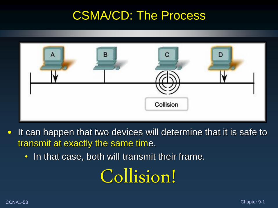
CSMA/CD: The Process
• It can happen that two devices will determine that it is safe to
transmit at exactly the same time.
• In that case, both will transmit their frame.
Collision!
CCNA1-54 Chapter 9-1
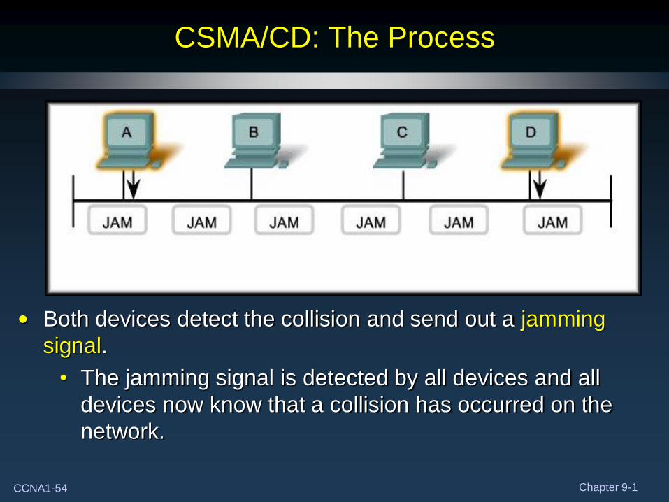
CSMA/CD: The Process
• Both devices detect the collision and send out a jamming
signal.
• The jamming signal is detected by all devices and all
devices now know that a collision has occurred on the
network.
CCNA1-55 Chapter 9-1
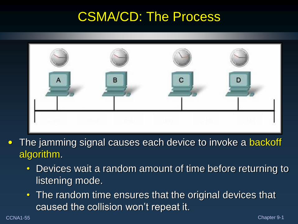
CSMA/CD: The Process
• The jamming signal causes each device to invoke a backoff
algorithm.
• Devices wait a random amount of time before returning to
listening mode.
• The random time ensures that the original devices that
caused the collision won’t repeat it.
CCNA1-56 Chapter 9-1
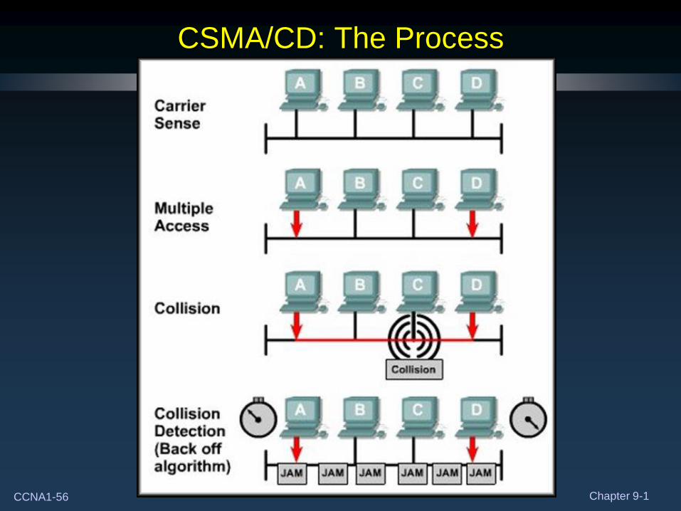
CSMA/CD: The Process
CCNA1-57 Chapter 9-1
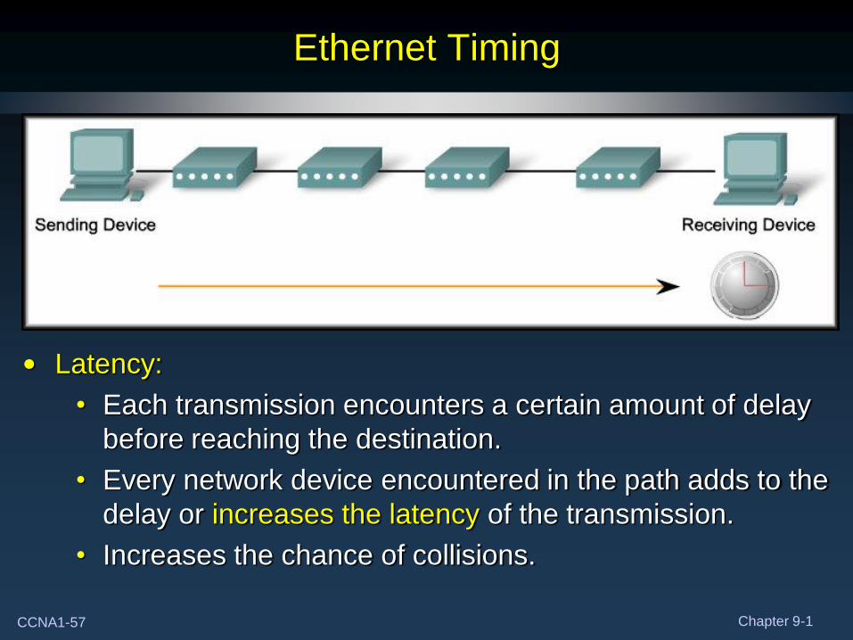
Ethernet Timing
• Latency:
• Each transmission encounters a certain amount of delay
before reaching the destination.
• Every network device encountered in the path adds to the
delay or increases the latency of the transmission.
• Increases the chance of collisions.
CCNA1-58 Chapter 9-1
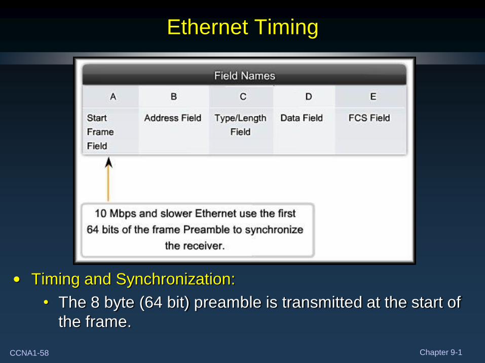
Ethernet Timing
• Timing and Synchronization:
• The 8 byte (64 bit) preamble is transmitted at the start of
the frame.
CCNA1-59 Chapter 9-1
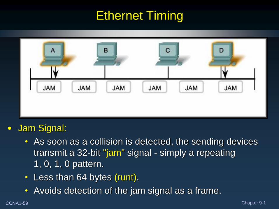
Ethernet Timing
• Jam Signal:
• As soon as a collision is detected, the sending devices
transmit a 32-bit "jam" signal - simply a repeating
1, 0, 1, 0 pattern.
• Less than 64 bytes (runt).
• Avoids detection of the jam signal as a frame.
CCNA1-60 Chapter 9-1
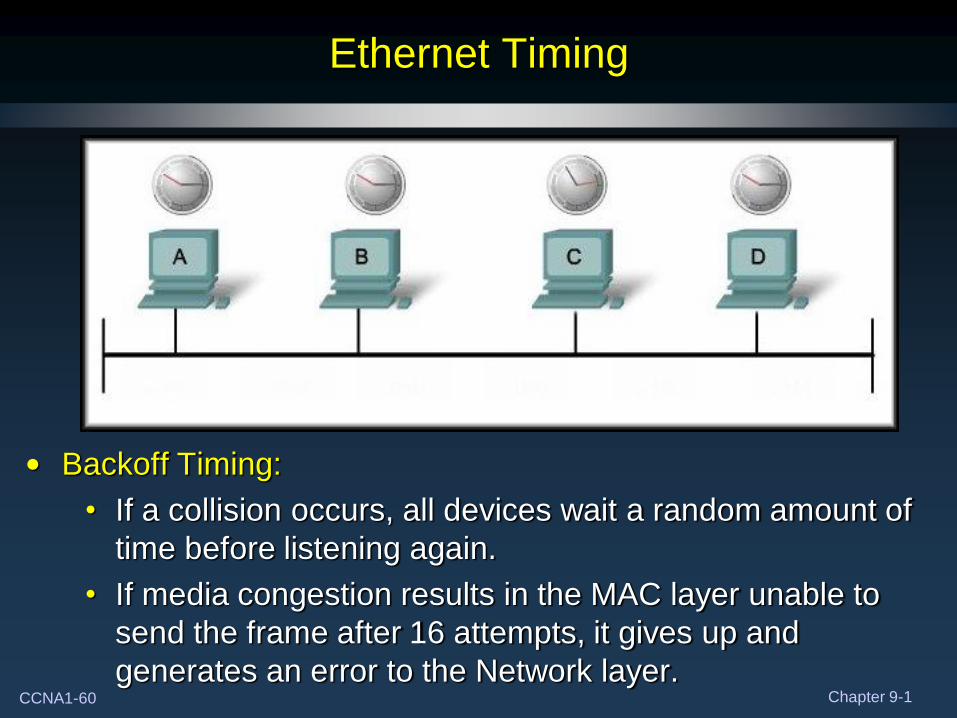
Ethernet Timing
• Backoff Timing:
• If a collision occurs, all devices wait a random amount of
time before listening again.
• If media congestion results in the MAC layer unable to
send the frame after 16 attempts, it gives up and
generates an error to the Network layer.