Embed Size (px)
Citation preview

Chapter 9
CULVERTS


Culverts 9-1
Chapter Table of Contents
9.1 Introduction ................................................................................................................. 9-4 9.2 Policy and Practice ...................................................................................................... 9-4 9.3 Large, Medium, and Small Culverts ......................................................................... 9-7 9.4 Sources of Information ............................................................................................... 9-7 9.5 Culvert Design Documentation .................................................................................. 9-8 9.6 Definitions .................................................................................................................... 9-8 9.7 Culvert Vertical Alignment ........................................................................................ 9-8
9.7.1 Use of Streambed Profiles in Design ................................................................ 9-9 9.7.1.1 Existing Profile .................................................................................. 9-9 9.7.1.2 Design Profile .................................................................................... 9-9 9.7.1.3 Long-Term Profile ........................................................................... 9-12
9.7.2 Culvert Invert Slope Versus Streambed Slope ................................................ 9-15 9.8 Culvert Horizontal Alignment ................................................................................. 9-18
9.8.1 Alignment, Bent Culverts ............................................................................... 9-18 9.8.2 Alignment, Multiple Barrel Culverts and Multiple Culverts .......................... 9-20
9.9 Alignment, Conflicts with Utilities ........................................................................... 9-21 9.10 Alignment, Construction Considerations ................................................................ 9-21 9.11 Fill Heights ................................................................................................................. 9-23 9.12 Minimum Culvert Size .............................................................................................. 9-25 9.13 Barrel Materials ........................................................................................................ 9-27 9.14 End Treatment........................................................................................................... 9-28 9.15 Culvert Design Flows ................................................................................................ 9-33 9.16 Peak vs. Attenuated Flows ........................................................................................ 9-34 9.17 Maximum Allowable Headwater ............................................................................. 9-35 9.18 Culvert Hydraulic Design ......................................................................................... 9-39
9.18.1 Headwater ....................................................................................................... 9-40 9.18.2 Tailwater ......................................................................................................... 9-41 9.18.3 Outlet Velocity ................................................................................................ 9-41 9.18.4 Performance Curves ........................................................................................ 9-41 9.18.5 Culverts Flowing in Inlet Control ................................................................... 9-42
9.18.5.1 Inlet Control Examples .................................................................... 9-42 9.18.5.2 Inlet Control Design Equations ........................................................ 9-46 9.18.5.3 Inlet Control Nomographs ............................................................... 9-55
9.19 Culverts Flowing in Outlet Control ......................................................................... 9-56 9.19.1 Outlet Control Examples................................................................................. 9-57 9.19.2 Outlet Control Hydraulics ............................................................................... 9-57 9.19.3 Outlet Control Nomographs ............................................................................ 9-66
April 2014 ODOT Hydraulics Manual

9-2 Culverts
9.19.4 Critical Depth .................................................................................................. 9-67 9.20 Procedure for Selection of Culvert Size .................................................................. 9-68 9.21 Example ...................................................................................................................... 9-71 9.22 Specialized Culverts .................................................................................................. 9-72
9.22.1 Culverts with Inlet Boxes and Access Holes .................................................. 9-73 9.22.2 Fish Passage Culverts ..................................................................................... 9-73 9.22.3 Open-Bottom Culverts .................................................................................... 9-73
9.22.3.1 Hydraulic Study and Documentation ............................................... 9-74 9.22.3.2 Minimum Culvert Size ..................................................................... 9-74 9.22.3.3 End Treatment .................................................................................. 9-76 9.22.3.4 Hydraulic Modeling ......................................................................... 9-76 9.22.3.5 Scour ................................................................................................ 9-78 9.22.3.6 Footing Protection ............................................................................ 9-78
9.22.4 Sag (Inverted Siphon) Culverts ....................................................................... 9-80 9.22.5 Detour Culverts, Construction Access Road Culverts, and Bypass Pipes ...... 9-81
9.23 Extending Existing Culverts ..................................................................................... 9-82 9.24 Scour at Culvert Outlets ........................................................................................... 9-83 9.25 Embankment Scour near Culverts .......................................................................... 9-84 9.26 Debris Control ........................................................................................................... 9-86 9.27 Piping .......................................................................................................................... 9-87 9.28 Flotation ..................................................................................................................... 9-87 9.29 Camber ....................................................................................................................... 9-88 9.30 Flap Gates .................................................................................................................. 9-88
Appendix A Culvert Performance Charts Appendix B Culvert Design Sheet Appendix C Debris-Control Structures
ODOT Hydraulics Manual April 2014

Culverts 9-3
--Figures-- Figure 9-1 Common Culvert Shapes ...................................................................................... 9-5 Figure 9-2 Common End Treatments ..................................................................................... 9-6 Figure 9-3 Stream Profiles ..................................................................................................... 9-11 Figure 9-4 Changes in Channel Profile Due to Headcuts ................................................... 9-16 Figure 9-5 Culvert Vertical Alignment ................................................................................ 9-17 Figure 9-6 Culvert Location .................................................................................................. 9-19 Figure 9-7 Stage Construction ............................................................................................... 9-24 Figure 9-8 Depressed and Tapered Inlets ............................................................................ 9-37 Figure 9-9 Headwater and Tailwater Diagram .................................................................... 9-38 Figure 9-10 Culvert Performance Curve ............................................................................. 9-44 Figure 9-11 Inlet Control Types ........................................................................................... 9-45 Figure 9-12 Prefabricated Concrete End Section Tested by K-TRANS ............................ 9-53 Figure 9-13 Prefabricated Metal End Section Tested by K-TRANS ................................ 9-54 Figure 9-14 Outlet Control Types ........................................................................................ 9-58 Figure 9-15 Full Flow Energy and Hydraulic Grade Lines ............................................... 9-60 Figure 9-16 Bend Loss Coefficients ...................................................................................... 9-62 Figure 9-17 Methods to Reduce Barrel Slope...................................................................... 9-75 Figure 9-18 Clearance for Open-Bottom Culvert ................................................................ 9-77 Figure 9-19 Typical Footing Protection Detail ..................................................................... 9-80 Figure 9-20 Sag (Inverted Siphon) Culvert .......................................................................... 9-81 Figure 9-21 Typical Culvert Embankment Protection Details ........................................... 9-85
--Tables-- Table 9-1 Factors Influencing Culvert Performance .......................................................... 9-41 Table 9-2 Constants for Inlet Control Design Equations ................................................... 9-50 Table 9-3 Entrance Loss Coefficients .................................................................................... 9-61
--Plates—
PLATE 1 ................................................................................................................................... 9-90 PLATE 2 ................................................................................................................................... 9-91 PLATE 3 ................................................................................................................................... 9-92
April 2014 ODOT Hydraulics Manual

9-4 Culverts
9.1 Introduction
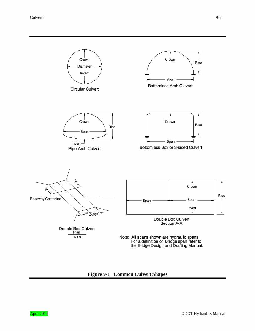
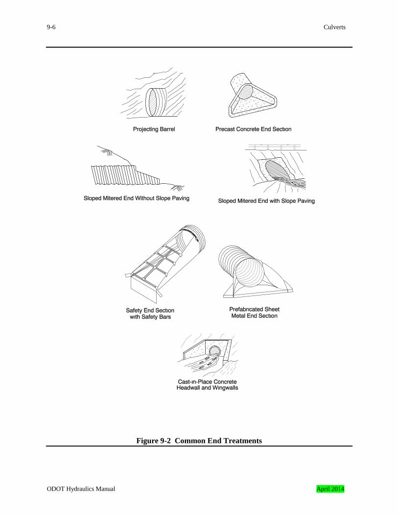
This chapter provides information for the planning and design of highway culverts. The methodology is intended for those with an understanding of basic hydrologic and hydraulic methods and some experience in the design of hydraulic structures. A culvert is a conduit that conveys stream flow or storm runoff through a roadway embankment or past some other flow obstruction. Culverts are constructed from a variety of materials and are available with many different shapes, sizes, and end treatments, as shown in Figures 9-1 and 9-2. Culvert selection factors include roadway profiles, channel characteristics, fish passage requirements, hydraulic performance, resistance to flotation, construction and maintenance costs, and estimated service life. Culverts may be cost-effective replacements for bridges at some sites. Culverts often do not provide the clearance for navigation, debris, ice, and fish passage as compared to bridges. In addition, scour downstream from a culvert outlet is often deeper and more extensive than scour downstream from a bridge. These factors should be considered before a culvert is recommended at the site of an existing bridge.
9.2 Policy and Practice General policies of the Federal Highway Administration (FHWA) and ODOT pertaining to hydraulic design are discussed in Chapter 3. ODOT practice specific to culvert design are as follows.
• Coordination with other Federal, state, and local agencies concerned with water resources planning will have a high priority in culvert design.
• Safety of the general public is an important consideration in culvert selection. • Culvert design shall consider the frequency and type of maintenance and make allowance
for maintenance equipment and personnel access. • Sediment deposition and scour shall be considered during culvert design and be minimized
when possible. • Environmental impacts of culverts such as fish passage and disturbance of fish habitat,
wetlands, and riparian areas must be considered and minimized as needed. • Culvert hydraulic performance during the design event shall consider the class of the
roadway, the consequences of traffic interruption, the flood hazard risks, economics, and local site conditions.
ODOT Hydraulics Manual April 2014
Culverts 9-5
Figure 9-1 Common Culvert Shapes
April 2014 ODOT Hydraulics Manual
9-6 Culverts
Figure 9-2 Common End Treatments
ODOT Hydraulics Manual April 2014
Culverts 9-7
9.3 Large, Medium, and Small Culverts Culverts are classified as large, medium, or small. The type and amount of data collected for the design, the complexity of the hydraulic study, and the level of documentation depends on the culvert classification. Regardless of culvert size, they are designed by a professional engineer registered in Oregon or others under the direct supervision of the engineer. Final plans and other documents require an engineer’s seal. This is discussed in Chapter 3. Large culverts are:
• circular culverts with diameters more than or equal to 72 inches, • arch-pipes with equivalent diameters more than or equal to 72 inches, • box culverts with spans more than or equal to 72 inches, • multiple barrel culverts with cumulative span widths more than or equal to 72 inches, • open-bottom culverts of all sizes, • culverts with complex hydraulic structures such as cast-in-place energy dissipators; drop,
side tapered, or slope-tapered inlets, etc. and • culverts providing fish passage regardless of size.
Medium culverts are:
• circular culverts with diameters more than or equal to 48 inches and less than 72 inches, • arch-pipes with equivalent diameters more than or equal to 48 inches and less than 72
inches, and • box culverts with spans more than or equal to 48 inches less than 72 inches.
Small culverts are:
• circular culverts with diameters less than 48 inches, • arch-pipes with diameters less than 48 inches, and • box culverts with spans less than 48 inches.
9.4 Sources of Information The type, source, and complexity of data for a culvert design will vary depending on the location and type of culvert. Large culverts typically require data similar to a bridge location survey, such as a vicinity map, stream or drainage profile and cross-sections, geologic data, etc. Small and medium culverts usually require less data and most of the information can be provided by
April 2014 ODOT Hydraulics Manual
9-8 Culverts
the roadway location survey. Often information and experience from other agencies can be used to supplement the location survey. This is especially important when fish passage is a concern, as the requirements and guidelines of fish management agencies may dictate the type, size and location of the culvert. Data requirements for typical culvert designs are listed in Chapter 6.
9.5 Culvert Design Documentation The documentation for large culverts is similar to bridges and large channel studies. Smaller and medium culverts require less documentation. Report and documentation guidelines are in Chapter 4.
9.6 Definitions Definitions for many terms used in culvert design are in the glossary at the end of this manual.
9.7 Culvert Vertical Alignment The vertical alignment of a culvert with respect to the stream is important to culvert hydraulic performance, stream stability, construction and maintenance costs, and the safety and integrity of the highway. Proper alignment is also of particular importance to promote fish passage, and to prevent outlet scour or excessive sediment buildup in the culvert barrels. A culvert placed too high in relation to the streambed may become a barrier to fish passage if the channel bottom degrades, or lowers, during the life of the facility. Conversely, a culvert placed too low in relation to the channel bottom may lose hydraulic performance if the channel aggrades, or rises. In addition, a culvert placed at a slope different than the natural channel slope may have problems related to both sediment deposition and bed material scour, and this affects both fish passage and hydraulic performance.
ODOT Hydraulics Manual April 2014
Culverts 9-9
9.7.1 Use of Streambed Profiles in Design Accurate assessment of streambed profiles is essential to determine potential changes in channel bottom elevations. It is important to:
• determine the profile of the existing streambed, called the “existing profile,” • estimate the profile the streambed will have immediately after the structure is
constructed, called the “design profile,” and • estimate the profile of the streambed throughout the life of the structure, called the “long-
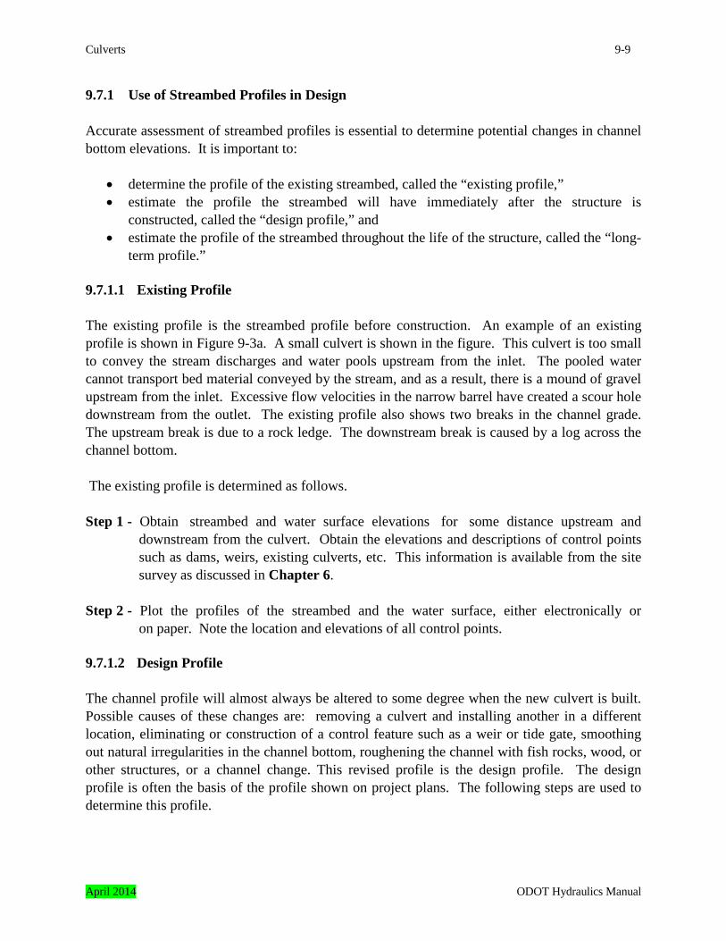
term profile.” 9.7.1.1 Existing Profile The existing profile is the streambed profile before construction. An example of an existing profile is shown in Figure 9-3a. A small culvert is shown in the figure. This culvert is too small to convey the stream discharges and water pools upstream from the inlet. The pooled water cannot transport bed material conveyed by the stream, and as a result, there is a mound of gravel upstream from the inlet. Excessive flow velocities in the narrow barrel have created a scour hole downstream from the outlet. The existing profile also shows two breaks in the channel grade. The upstream break is due to a rock ledge. The downstream break is caused by a log across the channel bottom. The existing profile is determined as follows. Step 1 - Obtain streambed and water surface elevations for some distance upstream and
downstream from the culvert. Obtain the elevations and descriptions of control points such as dams, weirs, existing culverts, etc. This information is available from the site survey as discussed in Chapter 6.
Step 2 - Plot the profiles of the streambed and the water surface, either electronically or
on paper. Note the location and elevations of all control points. 9.7.1.2 Design Profile The channel profile will almost always be altered to some degree when the new culvert is built. Possible causes of these changes are: removing a culvert and installing another in a different location, eliminating or construction of a control feature such as a weir or tide gate, smoothing out natural irregularities in the channel bottom, roughening the channel with fish rocks, wood, or other structures, or a channel change. This revised profile is the design profile. The design profile is often the basis of the profile shown on project plans. The following steps are used to determine this profile.
April 2014 ODOT Hydraulics Manual

9-10 Culverts
Step 1 - Obtain a copy of the existing profile. Locate the proposed structure on the profile. Note the limits of agency right-of-way or easements on the profile.
Step 2 - Estimate and plot the channel profile through the proposed structure. The design profile
grade will match the existing stream grade on some installations. Often when a fish-passage structure is built, irregularities in the channel bottom or barriers to fish passage caused by the existing structure are removed during construction, and these changes should be shown. Show control structures such as weirs on this profile if they will be needed. Check to see that all channel re-grading and control structures can be built within agency right-of-way or easements. If not, additional right-of-way or drainage easements may be needed.
An example of construction related changes are shown in Figure 9-3b. In the figure, a longer and larger embedded culvert will replace the smaller existing culvert. It is expected that the sediment mound will be removed and the scour hole will be filled during the construction of the new culvert. As a result, the design profile is expected to have a constant grade upstream and downstream from the culvert. The rock ledge and the log across the channel are shown on the design profile because they will not be affected by construction.
ODOT Hydraulics Manual April 2014
Culverts 9-11
Figure 9-3 Stream Profiles
April 2014 ODOT Hydraulics Manual
9-12 Culverts
9.7.1.3 Long-Term Profile Stream profiles often change with time. Changes in streambed profile are often called aggradation or degradation. Aggradation and degradation are the raising or lowering of the channel bottom elevation, respectively. An alteration to sediment continuity is the primary cause of these changes. Sediment continuity is a function of sediment supply and channel transport capacity. Sediment supply is provided by the upstream drainage. It is materials carried to the site by the stream, and the greatest amount of transport occurs during floods. Sediment transport capacity is the ability of the stream to move sediment along the streambed. Streams where the sediment supply exceeds the stream transport capacity tend to aggrade. Conversely, streams degrade when the transport capacity exceeds the sediment supply. A detailed discussion of sediment continuity with a list of factors causing changes is in FHWA Hydraulic Engineering Circular No. 20 “Stream Stability at Highway Structures.” These long-term changes in channel profile can reduce the ability of the culvert to pass fish, provide adequate hydraulic performance, and be structurally sound. Channel degradation can cause embedded, non-embedded, and baffled culverts to become barriers to fish passage. This occurs when the downstream end of the culvert becomes higher than the channel bottom, and fish cannot swim upstream through the barrel. This is often called a “perched” condition. Degradation can undermine open-bottom culvert foundations. Channel aggradation can reduce the flow capacity of all culvert types. Many factors can cause long-term changes in streambed profile. These causes are most often detected during a site visit. Typical items to investigate are in the following list.
1. Will a dam or other obstruction be built downstream that will decrease the flow velocity through the culvert? If the velocity is decreased, the ability of the stream to carry sediment will also be reduced, and the channel bed could aggrade in or near the culvert. This often occurs at the mouths of streams that discharge into newly constructed reservoirs.
2. Will a dam or other obstruction be removed upstream? The removal could be done by
man, such as the demolition of a dam, or by nature, such as the rotting and decomposition of a log across the channel. If the dam or other obstruction has retained bed material, its removal or failure can increase the amount of bed material passing though the site and the channel could aggrade. Conversely, removal of a dam that provides flood control could also increase the discharge and result in degradation.
ODOT Hydraulics Manual April 2014
Culverts 9-13
3. Will changes in land use increase runoff rates? Activities such as converting a forest into a pasture, or converting a forest or pasture to a housing or commercial development almost always increases the discharge. This frequently causes degradation.
4. Will a dam or other obstruction be removed downstream? If the obstruction has retained
bed material, the retained material can be carried downstream and the channel may degrade. In addition, if removing the obstruction increases flow velocities through the culvert site, the ability of the stream to carry sediment will also be increased, and the channel can degrade.
5. Will a dam or other obstruction be built upstream from the culvert site? If the obstruction
will interrupt the transport of bed material, the channel could degrade.
6. Will changes in land use change their sediment contribution? Improved erosion control in riparian corridors can reduce the amount of sediment washing into the streambed. Converting wildlands to housing or commercial developments can also reduce the sediment availability. This may result in channel degradation.
7. Will the stream be channelized upstream from the culvert? Channelization, especially
straightening the channel, can increase flow velocities through the site and cause the streambed to degrade. Conversely, restoring a straightened channel to a meandering waterway can decrease flow velocities and cause aggradation.
8. Is the streambed degrading due to natural erosion? Many streambeds are degrading due
to long-term erosion of the stream bottom that is caused by lack of sufficient sediment inflow into the channel (transport capacity > sediment supply). These streams are most often in “V” shaped channels on steep gradients and they probably have headcuts.
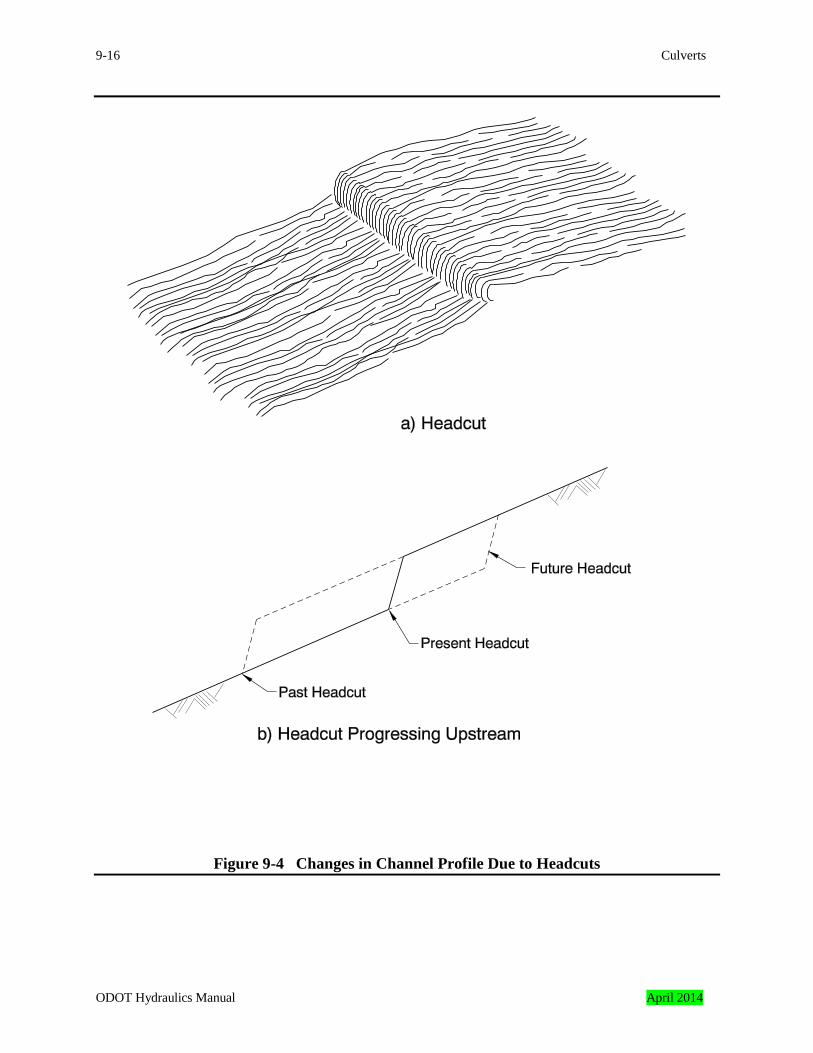
9. Are there headcuts downstream that may proceed upstream through the crossing site? A
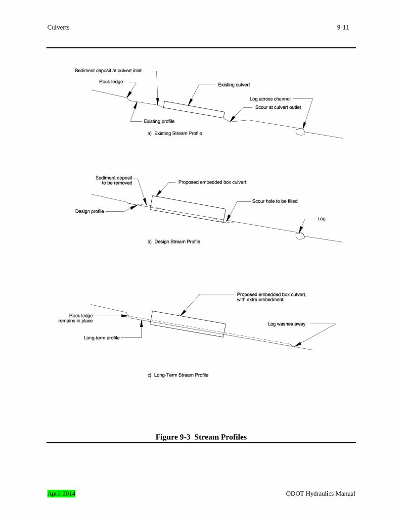
headcut is an abrupt change in channel elevation as shown in Figure 9-4a. Headcuts typically proceed upstream until they are stopped by a ledge of non-erodible rock or a structure such as a dam, a weir, or a culvert if the streambed is erodible. This migration is shown in Figure 9-4b. This type of erosion usually indicates that the streambed profile is readjusting after a change in channel slope, discharge, or sediment load characteristics. In channels with flowing water, headcutting is often shown by the presence of 12 to 18-inch high waterfalls or rapidly moving water in an otherwise placid river or stream. In dry channels, a relatively abrupt drop in the bed of an erodible channel is evidence of a headcut. Headcuts may range in depth from 1 to 9 feet or more. Niagara Falls is an example of a large headcut that is slowly progressing upstream in the Niagara River between Lake Erie and Lake Ontario.
April 2014 ODOT Hydraulics Manual
9-14 Culverts
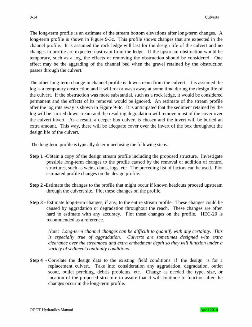
The long-term profile is an estimate of the stream bottom elevations after long-term changes. A long-term profile is shown in Figure 9-3c. This profile shows changes that are expected in the channel profile. It is assumed the rock ledge will last for the design life of the culvert and no changes in profile are expected upstream from the ledge. If the upstream obstruction would be temporary, such as a log, the effects of removing the obstruction should be considered. One effect may be the aggrading of the channel bed when the gravel retained by the obstruction passes through the culvert. The other long-term change in channel profile is downstream from the culvert. It is assumed the log is a temporary obstruction and it will rot or wash away at some time during the design life of the culvert. If the obstruction was more substantial, such as a rock ledge, it would be considered permanent and the effects of its removal would be ignored. An estimate of the stream profile after the log rots away is shown in Figure 9-3c. It is anticipated that the sediment retained by the log will be carried downstream and the resulting degradation will remove most of the cover over the culvert invert. As a result, a deeper box culvert is chosen and the invert will be buried an extra amount. This way, there will be adequate cover over the invert of the box throughout the design life of the culvert. The long-term profile is typically determined using the following steps. Step 1 -Obtain a copy of the design stream profile including the proposed structure. Investigate
possible long-term changes to the profile caused by the removal or addition of control structures, such as weirs, dams, logs, etc. The preceding list of factors can be used. Plot estimated profile changes on the design profile.
Step 2 -Estimate the changes to the profile that might occur if known headcuts proceed upstream
through the culvert site. Plot these changes on the profile. Step 3 - Estimate long-term changes, if any, to the entire stream profile. These changes could be
caused by aggradation or degradation throughout the reach. These changes are often hard to estimate with any accuracy. Plot these changes on the profile. HEC-20 is recommended as a reference.
Note: Long-term channel changes can be difficult to quantify with any certainty. This is especially true of aggradation. Culverts are sometimes designed with extra clearance over the streambed and extra embedment depth so they will function under a variety of sediment continuity conditions.
Step 4 - Correlate the design data to the existing field conditions if the design is for a
replacement culvert. Take into consideration any aggradation, degradation, outlet scour, outlet perching, debris problems, etc. Change as needed the type, size, or location of the proposed structure to assure that it will continue to function after the changes occur in the long-term profile.
ODOT Hydraulics Manual April 2014
Culverts 9-15
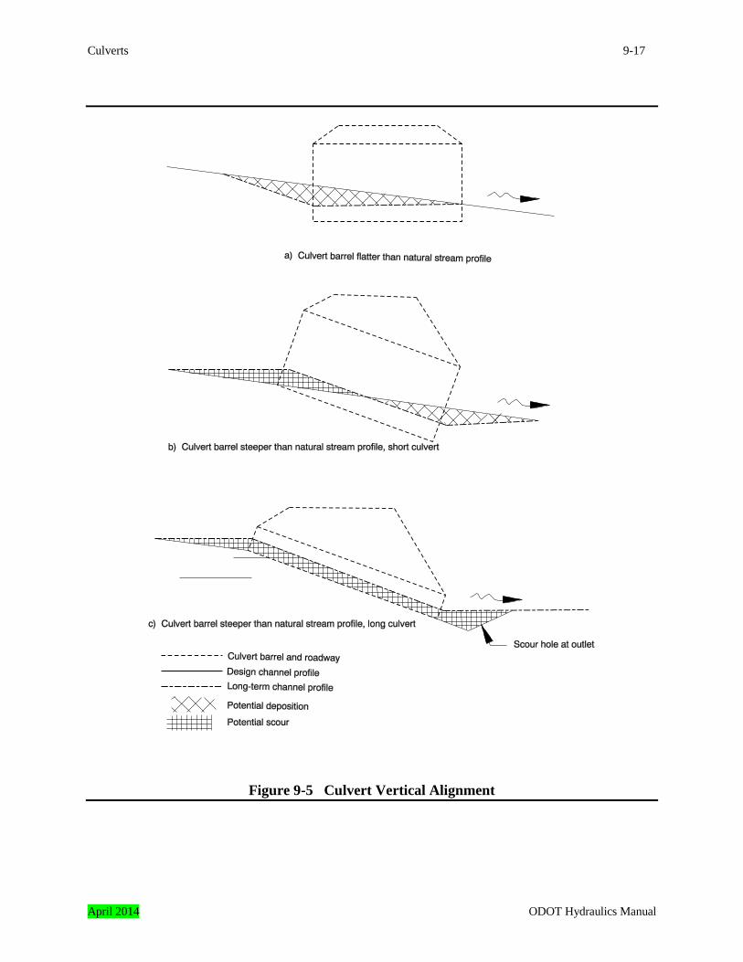
9.7.2 Culvert Invert Slope Versus Streambed Slope The culvert invert slope should match the stream bed slope. Placing the culvert on a flatter or steeper gradient than the natural streambed can cause sediment deposition in the barrel. It can also cause scour that removes sediment from the barrel. This is especially critical for fish passage culverts designed to have a sediment covered invert. Typical areas of deposition and scour are shown in Figure 9-5. Placing a culvert at a slope other than the natural streambed slope should be avoided. The following steps are recommended if it cannot be avoided. Step 1 - Estimate the streambed profile through the culvert after it attains its expected long-term
profile, including any deposition or scour. Step 2 - Check to assure the culvert will have adequate hydraulic capacity with the profile
determined in the previous step. The most common constriction point is the upper end of the barrel when culverts are installed at flatter slopes than the streambeds, as shown in Figure 9-5a. The constriction point can be at the lower end when the barrel is installed at a steeper slope than the streambed, as shown in Figure9-5b. Sometimes a taller or wider barrel will be needed.
Step 3 - If the culvert is installed on a steeper slope than the stream, check to assure the upstream
end of the culvert will retain a cover of bed material. Scour of bed material covering the upstream end is a common problem with culverts at slopes steeper than the natural channel. Scour of bed material throughout the barrel can be a problem with longer culverts, as shown in Figure 9-5c. It may be necessary to provide bed retention weirs within the culvert barrel. Consider the effects of these weirs on fish passage.
Step 4 - Periodic cleaning may be needed at some installations if a large enough barrel cannot be
provided. This cleaning should be described in the Hydraulics Report. Approval from ODOT maintenance should be obtained before a culvert is installed that will require periodic cleaning.
Step 5 - Provide access for maintenance forces if cleaning will be needed. This may include
easements, a turnout for vacuum cleaning trucks, access roads, etc. Step 6 - Verify the environmental documents describing the project impacts mention the need for
periodic cleaning. Permits are often needed for cleaning. Step 7 - Consider an overflow culvert if the subject culvert is susceptible to plugging due to
deposition.
April 2014 ODOT Hydraulics Manual
9-16 Culverts
Figure 9-4 Changes in Channel Profile Due to Headcuts
ODOT Hydraulics Manual April 2014
Culverts 9-17
Figure 9-5 Culvert Vertical Alignment
April 2014 ODOT Hydraulics Manual
9-18 Culverts
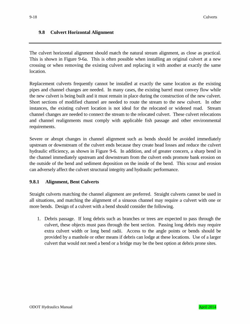
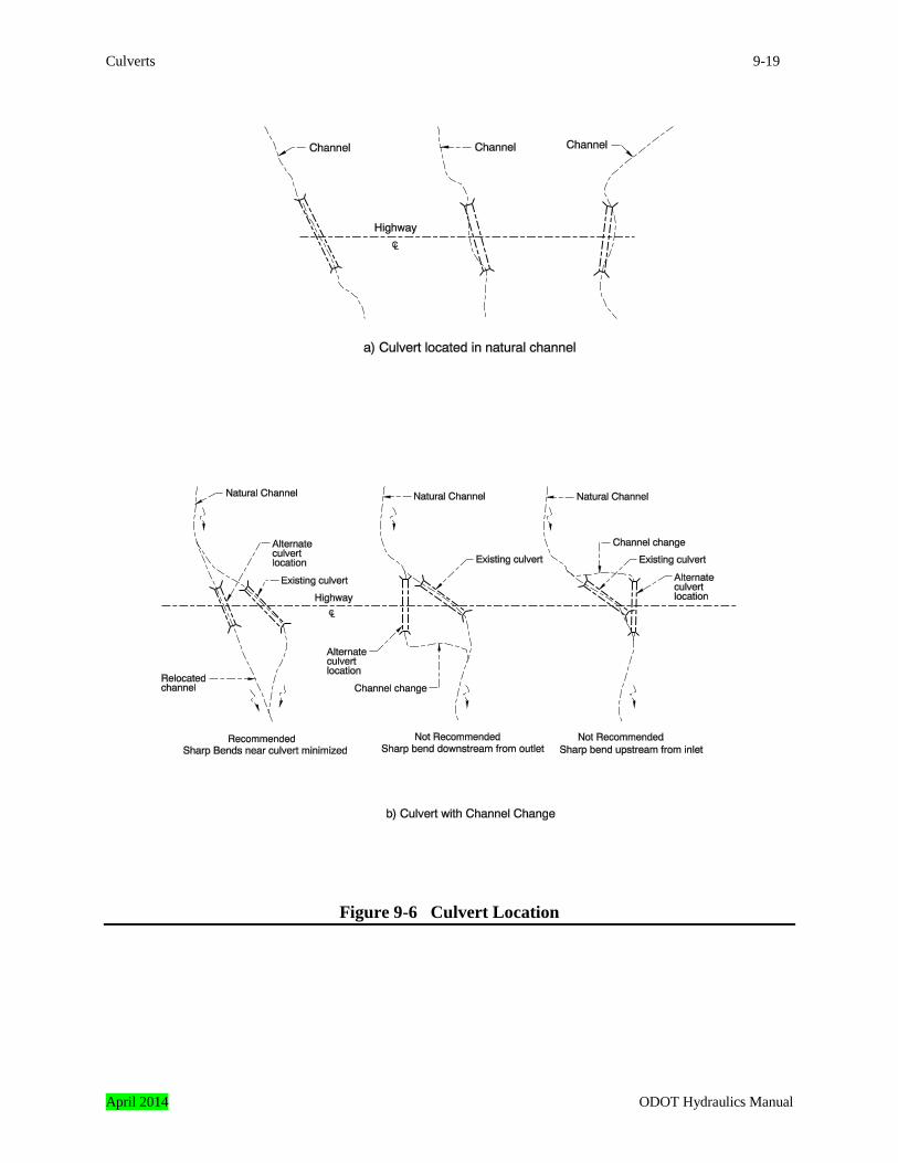
9.8 Culvert Horizontal Alignment The culvert horizontal alignment should match the natural stream alignment, as close as practical. This is shown in Figure 9-6a. This is often possible when installing an original culvert at a new crossing or when removing the existing culvert and replacing it with another at exactly the same location. Replacement culverts frequently cannot be installed at exactly the same location as the existing pipes and channel changes are needed. In many cases, the existing barrel must convey flow while the new culvert is being built and it must remain in place during the construction of the new culvert. Short sections of modified channel are needed to route the stream to the new culvert. In other instances, the existing culvert location is not ideal for the relocated or widened road. Stream channel changes are needed to connect the stream to the relocated culvert. These culvert relocations and channel realignments must comply with applicable fish passage and other environmental requirements. Severe or abrupt changes in channel alignment such as bends should be avoided immediately upstream or downstream of the culvert ends because they create head losses and reduce the culvert hydraulic efficiency, as shown in Figure 9-6. In addition, and of greater concern, a sharp bend in the channel immediately upstream and downstream from the culvert ends promote bank erosion on the outside of the bend and sediment deposition on the inside of the bend. This scour and erosion can adversely affect the culvert structural integrity and hydraulic performance. 9.8.1 Alignment, Bent Culverts Straight culverts matching the channel alignment are preferred. Straight culverts cannot be used in all situations, and matching the alignment of a sinuous channel may require a culvert with one or more bends. Design of a culvert with a bend should consider the following.
1. Debris passage. If long debris such as branches or trees are expected to pass through the culvert, these objects must pass through the bent section. Passing long debris may require extra culvert width or long bend radii. Access to the angle points or bends should be provided by a manhole or other means if debris can lodge at these locations. Use of a larger culvert that would not need a bend or a bridge may be the best option at debris prone sites.
ODOT Hydraulics Manual April 2014
Culverts 9-19
Figure 9-6 Culvert Location
April 2014 ODOT Hydraulics Manual
9-20 Culverts
2. Hydraulic efficiency. A bend may reduce the hydraulic efficiency of a culvert, and the more sudden and sharper the bend, the greater the loss in efficiency. Bend hydraulic losses do not affect culverts under inlet control. They may significantly reduce the hydraulic performance of culverts under outlet control. Smooth large radius bends are preferred if bends are needed. They have a less adverse effect on hydraulic performance.
3. Scour. A bend increases flow velocities inside the barrel at the outside of the bend and
downstream from the bend. The increased scour caused by these high velocities should be considered in the scour depth calculations and the footing designs of open-bottom arch culverts and 3-sided boxes. The locations of the higher shear stresses in bends are discussed in Chapter 8. The design of open-bottom culverts and 3-sided boxes is discussed within this chapter.
9.8.2 Alignment, Multiple Barrel Culverts and Multiple Culverts Single barrel culverts are preferred where they can be used. Multiple barrel culverts or multiple culverts may be used where limited vertical clearance between the roadway and the streambed or other reasons preclude use of a single barrel culvert. A double or triple barrel reinforced concrete box (RCBC) is an example of a multiple barrel culvert. Two or more separate corrugated metal pipes at a single site are an example of a multiple culvert. Alignment of either culvert type should consider the following.
1. Barrel spacing. The separate barrels of multiple culverts should be spaced apart in accordance with ODOT Standard Drawing RD300. This will ensure sufficient space is available to compact the backfill. The barrels can be spaced closer if the area around the bottom half of the barrel is backfilled with concrete.
2. Channel characteristics. Installation of multiple barrel culverts or multiple culverts in
channel bends or irregular channels may result in sediment deposition in one of the barrels. These problems can be minimized by relocating the culverts so they are in a straight reach of channel with a regular cross-section. Sometimes, with multiple barrel RCBCs, a sill is constructed across the apron to direct low flows into one barrel. A similar method is used with multiple culverts. One barrel is placed lower than the rest to handle the low flows and also to minimize potential sediment problems.
ODOT Hydraulics Manual April 2014
Culverts 9-21
9.9 Alignment, Conflicts with Utilities
Culvert alignment, both vertical and horizontal, is often affected by utilities because many culverts are located in the vicinity of existing or future utilities, such as power transmission towers, sewers, fiber optic cables, etc. ODOT often has given the utility an easement to locate on ODOT right-of-way, and part of the easement stipulates that the utility must be relocated if it conflicts with the ODOT facilities. ODOT can request that the utility be relocated in these cases. In other instances, ODOT may have to locate its facilities to keep them away from the utility or pay for the utility to be moved. This most often occurs where the utility is on private property. ODOT region utilities personnel are responsible for utility location and negotiations with the utility owners. The utility cannot always be relocated so it is far from the culvert. Instead, it will be near or adjacent to the structure. There are recommended minimum clearances between the utility and the culvert, in some instances. The utility company can often provide information about these clearances. The clearances can be reduced, or sometimes eliminated, if casings or other protection measures are installed around the utility. Utility corridors should also be considered if they are present. This could be an unoccupied corridor reserved for future utilities or space for additional utilities near existing utilities. An example would be a community that has overhead phone and electrical lines and intends to relocate the lines underground. Corridors may be reserved for the relocation. Precise utility location can be expensive because it requires detailed surveys. In some instances, excavation is needed to determine the exact utility location. As a result, preliminary culvert design is often done using limited utility data, a comprehensive utility location survey is made, and the detailed utility data is used in the final design. In all cases, the final culvert design should not be made until affected utilities are located. Unanticipated utility conflicts are almost always time consuming and expensive when they are resolved during construction.
9.10 Alignment, Construction Considerations Often the anticipated construction method affects the culvert alignment. There should be at least one possible method of constructing the culvert, and the construction procedure should be considered when the culvert is designed. The roadway designer is a useful source of information about construction methods and constraints. As an example, the need to maintain the flow of traffic through the project may require special construction considerations such as trenchless excavation or stage construction.
April 2014 ODOT Hydraulics Manual
9-22 Culverts
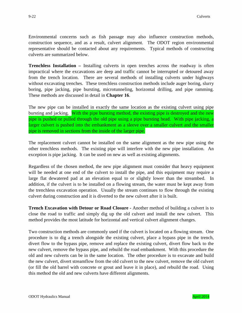
Environmental concerns such as fish passage may also influence construction methods, construction sequence, and as a result, culvert alignment. The ODOT region environmental representative should be contacted about any requirements. Typical methods of constructing culverts are summarized below. Trenchless Installation – Installing culverts in open trenches across the roadway is often impractical where the excavations are deep and traffic cannot be interrupted or detoured away from the trench location. There are several methods of installing culverts under highways without excavating trenches. These trenchless construction methods include auger boring, slurry boring, pipe jacking, pipe bursting, microtunneling, horizontal drilling, and pipe ramming. These methods are discussed in detail in Chapter 16. The new pipe can be installed in exactly the same location as the existing culvert using pipe bursting and jacking. With the pipe bursting method, the existing pipe is destroyed and the new pipe is pushed or pulled through the old pipe using a pipe bursting head. With pipe jacking, a larger culvert is pushed into the embankment as a sleeve over a smaller culvert and the smaller pipe is removed in sections from the inside of the larger pipe. The replacement culvert cannot be installed on the same alignment as the new pipe using the other trenchless methods. The existing pipe will interfere with the new pipe installation. An exception is pipe jacking. It can be used on new as well as existing alignments. Regardless of the chosen method, the new pipe alignment must consider that heavy equipment will be needed at one end of the culvert to install the pipe, and this equipment may require a large flat dewatered pad at an elevation equal to or slightly lower than the streambed. In addition, if the culvert is to be installed on a flowing stream, the water must be kept away from the trenchless excavation operation. Usually the stream continues to flow through the existing culvert during construction and it is diverted to the new culvert after it is built. Trench Excavation with Detour or Road Closure - Another method of building a culvert is to close the road to traffic and simply dig up the old culvert and install the new culvert. This method provides the most latitude for horizontal and vertical culvert alignment changes. Two construction methods are commonly used if the culvert is located on a flowing stream. One procedure is to dig a trench alongside the existing culvert, place a bypass pipe in the trench, divert flow to the bypass pipe, remove and replace the existing culvert, divert flow back to the new culvert, remove the bypass pipe, and rebuild the road embankment. With this procedure the old and new culverts can be in the same location. The other procedure is to excavate and build the new culvert, divert streamflow from the old culvert to the new culvert, remove the old culvert (or fill the old barrel with concrete or grout and leave it in place), and rebuild the road. Using this method the old and new culverts have different alignments.
ODOT Hydraulics Manual April 2014
Culverts 9-23
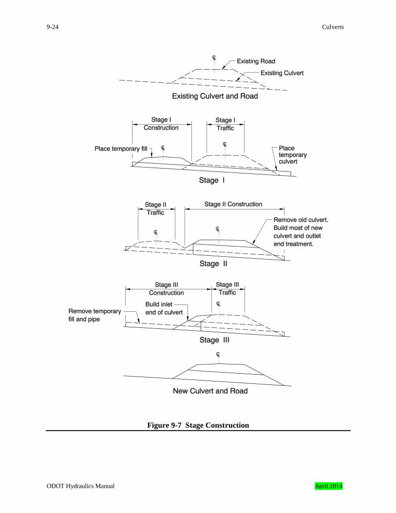
Trench Excavation with Stage Construction – With this method the highway remains open to traffic and the new culvert is built in the same or different location than the old culvert. This procedure is illustrated in Figure 9-7 and it requires careful planning. To summarize the procedure, a long bypass pipe is placed inside the existing culvert and flow is diverted into the bypass pipe. Then a temporary fill and roadway is built alongside the existing road and over one end of the bypass pipe. Traffic is diverted to the temporary road, and a portion or the entire existing culvert is removed and replaced. Last, traffic is rerouted over the new section of culvert, the temporary roadway is removed, the remainder of the old culvert is removed and replaced, and the bypass pipe is removed. There must be sufficient clearance inside the new culvert for both the bypass pipe and construction activity if the stage-construction method is used. For example, if a structural plate pipe-arch is to be built, there must be enough room in the new culvert for both the bypass pipe and the workers bolting the culvert together.
9.11 Fill Heights
An important factor in culvert sizing and vertical alignment is the distance between the surface of the subgrade or the pavement and the culvert crown. This is typically called “cover thickness” or “fill height.” Fill height limitations often influence the choice of the culvert barrel material or the maximum diameter or rise of the culvert. At a minimum, there should be enough fill over the culvert to dissipate the wheel loads from construction activities or traffic. Minimum cover is measured from the subgrade surface to the pipe crown. This distance is usually at its minimum at the roadway shoulder over the upstream end of the pipe but should be checked over the length of the culvert.
April 2014 ODOT Hydraulics Manual
9-24 Culverts
Figure 9-7 Stage Construction
ODOT Hydraulics Manual April 2014
Culverts 9-25
At a maximum, the weight of the fill over the culvert should not be great enough to damage or distort the culvert. Maximum cover is measured from the finished road surface to the pipe crown. It is usually greatest at the roadway shoulder over the downstream end of the pipe but should be checked over the entire length of the culvert. Fill height tables for metal pipes, concrete pipes, corrugated polyethylene pipes, and cast-in-place concrete box culverts are in the ODOT Standard Drawings. Fill heights for precast box culverts are listed in the American Association of State Highway and Transportation Officials (AASHTO) "Standard Specifications for Transportation Materials." Fill heights for polyvinyl chloride plastic pipes are in Chapter 5. Fill heights for the various bottomless arch and 3-sided box culverts are in the trade literature. Methods to protect pipes having minimal cover, and procedures to protect pipes from damage due to high fills, are discussed in Chapter 5. Guardrail support is not a factor in calculating cover heights in most circumstances. There are several rail types that do not have posts projecting into the fill directly over the culvert barrel. Post penetration should be considered in fill height calculations if posts cannot be avoided. Guardrail posts can project 3-1/2 to 4-1/2 feet into the roadway. Exact post and guardrail dimensions are in the ODOT Standard Drawings.
9.12 Minimum Culvert Size The minimum culvert size is the larger of the following:
• the minimum size allowed by ODOT design criteria, including fish passage and environmental criteria,
• the minimum size that produces an allowable headwater elevation (Section 9.17), • the minimum size that allows access for maintenance , if needed, • the minimum size that will allow passage of stream bed material, and • for bottomless culverts, the minimum size that results in acceptable scour depths.
ODOT Design Criteria - ODOT design criteria specify minimum culvert sizes at many locations, as described in the following list.
• The minimum diameter for median culverts shall be 18 inches unless they are connected to a grated inlet or catch basin, in which case, the minimum diameter shall be 15 inches.
• Culvert pipe under roadway approaches shall have a minimum diameter of 12 inches. These roadway approaches are driveways, minor access roads, etc. Roadway culvert criteria apply to culverts under roadways that intersect the main highway.
• The minimum diameter for roadway cross-culverts shall be 18 inches. The minimum diameter for installations longer than 150 feet or under more than 15 feet of fill shall be 24 inches. Consideration should be given to using a 36-inch minimum diameter on interstate
April 2014 ODOT Hydraulics Manual
9-26 Culverts
routes. Clearance for Maintenance – Culverts with buried inverts on waterways where fish passage is required should provide clearance for channel maintenance such as removing obstructions or replacing lost bed material. Culverts with fish baffles or weirs should provide clearance for inspection, cleaning, and repair. Open-bottom arches or 3-sided boxes should provide clearance for cleaning, footing inspection, footing repair, and renewal of revetment protecting the footings, as discussed in Subsection 9.22.3. ODOT maintenance should be contacted for preferred horizontal and vertical clearances. Maintenance usually requests an 8-foot by 8-foot opening. Passage of Streambed Material – Almost all ODOT culverts intended to pass fish are designed to retain a layer of bed material over their invert. They are also aligned and sized to minimize scour at the outlet and bed material deposition at the inlet. This is done by providing adequate hydraulic capacity for sediment continuity. Sediment continuity is a balance between the bed load the stream transports into the culvert during floods versus the amount of bed material carried out of the culvert during the same flood. The concept of sediment continuity is discussed in the FHWA publications Hydraulic Design Series No. 6 “River Engineering for Highway Encroachments” (HDS#6) and Hydraulic Engineering Circular No. 20 “Stream Stability at Highway Structures” (HEC#20). Culvert design using the principles in HDS#5 and HEC#20 is beyond the scope of this chapter. At present, these guidelines can also be used to determine the minimum culvert span needed to pass streambed material. Case 1 – Span the waterway, or channel width, that conveys the Ordinary High Water (OHW). OHW is defined in Chapter 6. In almost all instances the majority of sediment is transported within this waterway. This minimum span length is best suited for culverts meeting all of the following:
• culverts on straight stream reaches, • culverts well aligned to the flow, • culverts that do not go under pressure flow during the design flood, • sites where most of the discharge is within the channel during floods, • sites where the stream is stable in both vertical and horizontal alignment, • sites where the hydrology can be determined with a fair degree of certainty, and • sites without a history of problems related to excessive bed load or debris transport.
Case 2 – Span 125 percent of the width of the waterway that conveys the Ordinary High Water plus two feet. This is a minimum waterway width criteria used successfully by other agencies. It is a larger waterway than Case 1, and it is best suited for culverts or sites having any one of the following characteristics:
• culverts on curved stream reaches, • culverts that cannot be well aligned to the flow, • sites where there is considerable overbank flow during floods,
ODOT Hydraulics Manual April 2014
Culverts 9-27
• sites where the stream may not be stable in either vertical or horizontal alignment, • sites where there is greater than normal uncertainty in determining the hydrology, and • sites with a history of problems related to excessive bed load or debris transport.
These are general guidelines. Regulatory agency guidelines may supercede these criteria in some circumstances.
9.13 Barrel Materials Culvert barrels are made from a variety of materials. Barrel material selection is based on hydraulic and structural considerations, corrosion and abrasion resistance, the design life of the facility and the service life of the culvert, local government preference, and the need for experimental installations. Guidelines for barrel material selection follow.
1. Materials must comply with requirements in the ODOT "Alternate Materials Policy for Pipe Materials," as discussed in Chapter 5.
2. The barrel material must have an adequate design life for the specific site conditions.
Special considerations are needed for pipes installed in corrosive conditions or culverts carrying abrasive sediments. Culvert design lives are listed in Chapter 5.
3. Culverts designed for fish passage must comply with applicable requirements.
4. Concrete pipe or box sections should not be used without pipe anchors on slopes steeper
than 4 Horizontal: 1 Vertical because differential settlement may open the joints. Cast-in-place reinforced concrete structures are acceptable on these steep slopes.
Culvert barrels should be standard sizes whenever possible. Many circular, pipe-arch, and semi-circular arch sizes are listed in Chapter 8 Appendix B and the fill height tables in the ODOT Standard Drawings. Many cast-in-place reinforced concrete box sizes are listed in the ODOT Standard Drawings. Precast concrete box culvert sizes are listed in Chapter 8 Appendix B and the American Association of State Highway and Transportation Officials (AASHTO) "Standard Specifications for Transportation Materials." Sizes of smooth wall polyvinyl chloride pipe are listed in Chapter 5. Sizes of the various non-semicircular open-bottom arches and 3-sided boxes are listed in the trade literature.
April 2014 ODOT Hydraulics Manual
9-28 Culverts
9.14 End Treatment The choice of end treatment depends on many interrelated and sometimes conflicting considerations. The designer must evaluate safety, aesthetics, the ability to pass debris, hydraulic efficiency, scouring, and economics. In addition, the end treatment should be consistent with ODOT design criteria unless the exception is approved by the ODOT Geo-Environmental Section’s Engineering and Asset Management Unit. This subsection describes many commonly used end treatments, their advantages and disadvantages, and ODOT design practice. Projecting Ends - A projecting end is a treatment where the culvert protrudes out of the embankment, as shown in Figure 9-2. This end treatment is seldom used on permanent installations, especially with large culverts. Its most common use is on temporary detour pipes and bypass pipes for temporary water management. Projecting ends have these advantages.
• They are the most simple and economical end treatment. • The inlet edge of a projecting metal culvert has a ring structure with more bending
resistance than a non-reinforced sloped end. Projecting ends have these disadvantages.
• They produce more inlet and outlet head losses than other end treatments because they provide no flow transition into or out of the culvert. An exception is the socket or groove end of a concrete pipe.
• From an aesthetic standpoint, projecting ends may not be desirable in areas exposed to public view.
• They have a poor ability to pass debris. Material carried by the stream, especially woody debris, can snag on the inlet edge.
• Metal pipes with projecting ends are especially vulnerable to uplift from buoyant forces. • Although the end of a projecting culvert offers some bending resistance, it is vulnerable to
damage and collapse if flows carry debris and the culvert is operating under a high headwater. Reinforced sloped ends or headwalls with wingwalls offer greater bending resistance.
• Projecting ends do not have cutoff walls to protect the culvert end or embankment from being undermined by scour. The segments near the ends of concrete pipes with projecting ends are especially vulnerable to separation at the joints if there is embankment scour.
ODOT practice for projecting ends is as follows.
• Projecting ends cannot be used for circular culverts with diameters of 72 inches or greater or the equivalent pipe arch size, or semi-circular bottomless arches with spans of 72 inches or greater.
• Projecting ends are not allowed for culvert ends in unshielded areas within the clear zone,
ODOT Hydraulics Manual April 2014
Culverts 9-29
approach road culverts in cut ditch sections, or on shallow flat sloped embankments five feet or less in height.
• Projecting ends are not allowed on outward helical spiral rib pipe. • Projecting ends are not suitable for many locations as discussed in this subsection.
Sloped Ends - Sloped ends with the barrel ends cut to match the fill slopes are the standard end treatment for circular, pipe-arch, and bottomless metal arch culverts. These ends are often called mitered ends, as shown in Figure 9-2. Details are shown on Standard Drawings RD318 for concrete pipes, and RD316 for metal and plastic pipes. Slope paving is a rectangular shaped section of reinforced concrete fabricated around the sloped end. It reinforces the end against bending, provides scour protection, and makes it easier to mow the embankment around the culvert end. ODOT Standard Drawing RD 320 shows slope paving on concrete and metal pipes. Reinforced concrete collars are a type of slope paving that fits around the upper half of the pipe in a ring shape, rather than the rectangular shape associated with slope paving. The collar around the lower half of the pipe resembles slope paving, and like slope paving, a cutoff wall is included. This end treatment provides most of the benefits of slope paving with a savings in material and fabrication costs. Concrete collars are rarely cost-effective for smaller pipe sizes. When collars are considered during design, it is most often for circular culverts of 66-inch diameter or larger or the equivalent pipe arch size. Advantages of sloped ends are as follows.
• They are simpler and less expensive than headwalls with wingwalls. • In the case of metal culverts, they are more hydraulically efficient than projecting ends. • They are more aesthetically pleasing than projecting ends. • They are less of a hazard to traffic than projecting ends. For this reason the safety end
section version of the sloped end is used in many locations. Safety bars can be fitted to the safety end sections to increase the chances that vehicles will pass over the inlets without damage or injury to the driver. This end treatment is shown in Figure 9-2 and details are shown on Standard Drawings RD324 for concrete pipe and RD322 for metal pipe. Safety end sections with paved end slopes are not shown on the standard drawings. If a paved end slope is needed for an inlet with safety bars it resembles the paved end slope shown on Standard Drawing RD320.
Disadvantages of sloped ends are:
• The inlet edges of sloped ends on metal culverts are especially susceptible to bending and uplift caused by high flows, collisions with debris, or contact with maintenance equipment. This is especially true for ends with flatter slopes and non-reinforced skewed ends on open-
April 2014 ODOT Hydraulics Manual
9-30 Culverts
bottom arches or 3-sided boxes. • Sloped ends of both metal and concrete culverts can be undermined by scour. To prevent
this damage, sloped ends are often protected by cutoff walls on both ends, as shown on Standard Drawing RD320. In addition, if concrete pipe is used, the sections of pipe near the ends are linked with tie bars as shown on ODOT Standard Drawing RD318.
• Sloped inlets on vegetated slopes are often hard to locate and mow around. To prevent these problems slope paving is required in some applications, as discussed in the remainder of this subsection.
ODOT practice for sloped ends within the clear zone that are not shielded from traffic is as follows.
1. Culverts parallel to the roadway centerline under driveways, road approaches, etc.
a. Pipe diameters less than or equal to 24 inches and posted speed more than or equal
to 45 miles per hour, provide 1V: 6H sloped end or safety end section. No safety bars are required.
b. Pipe diameters less than or equal to 24 inches and posted speed less than 45 miles
per hour, provide 1V: 4H sloped end or safety end section. No safety bars required.
c. Pipe diameters more than 24 inches and posted speed more than or equal to 45
miles per hour, provide 1V: 6H safety end section with safety bars. d. Pipe diameters more than 24 inches and posted speed less than 45 miles per hour,
provide 1V: 4H safety end section with safety bars.
e. Multiple pipes with diameters more than or equal to 15 inches, provide safety end sections with safety bars, using above criteria.
2. Cross-culverts:
a. Pipe diameters less than or equal to 36 inches, provide either a sloped end to match
embankment slope, or a 1V: 6H or 1V: 4H safety end section. No safety bars are required. The embankment slope should be warped and shaped to match the safety end section
b. Pipe diameters more than 36 inches, provide either a sloped end with safety bars to
match the embankment slope, or a 1V: 6H or 1V: 4H safety end section with safety bars.
c. Multiple pipes with diameters more than or equal to 36 inches, provide either a
sloped end, with safety bars to match embankment slope, or a 1V: 6H or 1V: 4H
ODOT Hydraulics Manual April 2014

Culverts 9-31
safety end section with safety bars. Note: Provide safety bars at the inlet if there are safety bars at the outlet, regardless of whether or not the inlet is in the clear zone. Additional ODOT design practice for sloped ends is as follows.
• Sloped ends are the standard end treatment for circular, pipe-arch, and metal arch culverts with diameters of 72 inches or greater, or the equivalent pipe-arch or arch size. Both ends will be sloped if this treatment is used.
• Reinforced concrete slope paving or collars are required on sloped ends of culverts with diameters equal to or greater than 72 inches. A cutoff wall with a depth of at least 36 inches is required on both ends.
• Slope paving on culverts with diameters less than 72 inches should include a cutoff wall on both ends with a minimum depth of ½ the barrel diameter or 1 foot, whichever is greater.
• Sloped ends with slope paving or safety end sections with slope paving are required on slopes that are 1V: 3H or flatter that will be mowed, or on the main roadways and interchange ramps of interstate highways. Slope paving will be used on both ends of the culvert if it is used. Contact the appropriate District Manager to determine if the slope will be mowed.
• Sloped ends or safety end sections are required on all approach road culverts in cut ditch sections or shallow flat sloped embankments, five feet or less in height.
• Sloped ends on plastic pipes are allowed only in locations where slope paving is required. • Skew cut sloped ends are not permitted for arch-type pipes. The roadway slopes will be
contour-graded to conform with the pipe as shown in detail “Alternate Skew Plan,” Standard Drawing RD320, for arch-type pipes on a skewed alignment with sloped ends.
Headwalls with Wingwalls - Headwalls with wingwalls are the standard end treatment for box culverts and they are occasionally used on circular, pipe-arch, and bottomless culverts. Headwalls and wingwalls for circular pipes and box culverts are shown on Figure 9-2 and ODOT Standard Drawing BR800, respectively. The upstream headwall has a beveled edge to improve hydraulic efficiency. Beveled edges can also be incorporated into the headwall to improve the efficiency of circular pipes, arch-pipes, bottomless arches, and other shapes. This end treatment has these advantages.
• It is one of the most hydraulically efficient end treatments and the cutoff walls protect the culvert ends from undermining due to scour.
• The weight of this end treatment holds the culvert down and it can prevent buoyant failure. • They are very efficient at passing debris.
A disadvantage of this end treatment is its relatively high complexity and cost as compared to other end treatments. ODOT design practice for headwalls with wingwalls is as follows.
April 2014 ODOT Hydraulics Manual
9-32 Culverts
• Headwalls with wingwalls are an optional end treatment for culverts. Both ends will have
headwalls with wingwalls if this option is used. Culverts with diameters equal to or larger than 72 inches should have a cutoff wall with a minimum depth of 36 inches. Culverts with diameters less than 72 inches should have a cutoff wall extending downward the greater distance of ½ the barrel diameter or 1 foot.
• Headwalls with wingwalls are not to be used for culvert ends in unshielded areas within the clear zone, approach road culverts in cut ditch sections, or on shallow flat sloped embankments five feet or less in height.
Concrete Boxes with Grates - Concrete boxes with grates are often used on small culverts draining medians, swales, gutters, depressions in paved surfaces, or roadside ditches. Details of these boxes are shown on Standard Drawings RD364, RD366, RD368, RD370, RD374, and RD378. Applicable safety standards apply to these ends within the clear zone. Prefabricated End Sections - Prefabricated end sections such as precast end sections for concrete pipes and flared sheet metal ends for metal pipes are shown in Figure 9-2. In many cases, these prefabricated end sections look better and are more hydraulically efficient than projecting or sloped ends. Prefabricated metal end sections have cutoff walls to resist undermining due to scour. Prefabricated concrete end sections, however, do not have cutoff walls and they are vulnerable to scour unless a cutoff wall is constructed under the edges of their aprons. A cutoff wall should extend downward to the greater of ½ the pipe diameter or 1 foot. Although a cutoff wall is the best protection against scour, riprap around the end is also an option. There are limitations and conditions on prefabricated end section use. These ends, with the exception of the safety end sections, are not approved by ODOT for use within the clear zone in locations unshielded from traffic. They may be used in areas shielded from traffic, only. In addition, ODOT does not have standard plans for the pipe connection details and installation of prefabricated end sections. As a result, plan details are prepared for each installation. Prior approval should be obtained from the Region Technical Center staff before these end sections are included in project plans. Depressed and Tapered Inlets - A variety of depressed and tapered inlets are used to increase the capacity of a culvert flowing under inlet control. Three types of these inlets, the depressed, the side-tapered, and the slope-tapered inlets are shown in Figure 9-8. Outlet end treatments on culverts with these inlets are usually headwalls with wingwalls. The hydraulic design of these inlets is beyond the scope of this manual and it is covered in the FHWA’s HDS #5 “Hydraulic Design of Highway Culverts.” These inlets have these advantages.
• The depressed inlet is most often used to reduce the barrel size or lower the headwater elevations to an acceptable level. This can be done because of this inlet has greater hydraulic efficiency. In comparison to a conventional inlet, for a given headwater elevation the depressed inlet provides greater headwater depth above the control section at the
ODOT Hydraulics Manual April 2014
Culverts 9-33
upstream end of the barrel (inlet control only). This increased headwater depth produces additional pressure to push the flow through the barrel.
• The depressed inlet provides a drop in elevation between the upstream edge of the inlet apron and the culvert invert. This may be useful if a lower barrel is needed to provide clearance for utilities or pavement. In addition, this inlet can be used to reduce the slope of a culvert and lower outlet velocities.
• The slope-tapered inlet provides the same benefits as the depressed inlet. It provides much greater hydraulic efficiency due to the gradual taper of the inlet throat section.
• The side-tapered inlets do not provide a drop but they have increased hydraulic efficiency when compared to conventional inlets. They may be cost effective in certain situations because they can reduce barrel size. They may also be added to existing barrels to increase their flow capacity.
These inlets have these disadvantages.
• They have a relatively high cost compared to other end treatments. They are specially designed for each application and they require forming reinforced concrete into shapes.
• These inlets are rarely adequate for fish passage. • These inlets may be more susceptible to clogging than conventional inlets in heavy debris
areas. ODOT practice for depressed or tapered inlets follows.
• Depressed or tapered inlets are an optional end treatment for culverts. A reinforced concrete collar, slope paving, or a headwall with wingwalls should be used at the outlet. Culverts with diameters equal to or larger than 72 inches should have a cutoff wall with a minimum depth of 36 inches. Culverts with barrels less than 72 inches diameter should have a cutoff wall that extends downward the greater distance of ½ the barrel diameter or 1 foot.
• Depressed or tapered inlets are not to be used for culvert ends in unshielded areas within the clear zone, approach road culverts in cut ditch sections, or on shallow flat sloped embankments five feet or less in height.
• Depressed or tapered inlets are not to be used for culverts in debris prone areas or where fish passage is required.
9.15 Culvert Design Flows An essential step in culvert design is to determine the flood flow versus recurrence interval relationship. Design and check flood recurrence intervals are listed in Chapter 3, the contents of the hydrology section of a Hydraulics Report are discussed in Chapter 4, and hydrologic methods are presented in Chapter 7.
April 2014 ODOT Hydraulics Manual
9-34 Culverts
The discharges used in culvert design are different for large, medium, and small culverts. The culvert size classification is defined at the beginning of this chapter. Discharges used in large culvert and some medium culvert designs are:
• the 6-month flow for selection of invert protection (see Chapter 5), • the Design Event (typically the 25 or 50-year storm event, and in some instances, the 100-
year flood, • the 100-year Base Flood, and • the check flood. The check flood is one of the two flows listed below that results in the
highest headwater elevations and outlet flow velocities, the Overtopping Flood, or the 500-year Flood.
Discharges used in small culvert and some medium culvert designs are:
• the 6-month flow for selection of invert protection (see Chapter 5), or • the Design Event (typically the 10-year storm event for road approach culverts, or the 25-
year or 50-year storm events for cross-culverts), and • the Check Flood. The check flood is the more frequent of: the Overtopping Flood, or the 100-year base flood.
Note: The invert protection design is based on sediment and bed material conveyed by the 6-month discharge. This is adequate for most installations. Greater floods may transport larger material at some sites. Designing the invert to resist damage from these greater and less frequent floods is recommended for costly or critical installations. Culverts are also used for temporary installations such as detours around construction sites, temporary water management, and other applications. Guidance about the discharges to use in their design is provided in Chapter 3.
9.16 Peak vs. Attenuated Flows Discharge increases to a maximum and then recedes when runoff from a storm event passes a point on a stream. The maximum discharge rate is called the peak flow. A culvert is sized to pass this peak flow from one side of the roadway embankment to the other without producing an excessive headwater elevation using the design method presented in this manual. Often there is considerable volume in the floodplain upstream from the culvert, and a significant amount of water can be stored in this area without producing an excessive headwater elevation. This storage can be considered in the culvert analysis. When upstream storage is considered, it will
ODOT Hydraulics Manual April 2014
Culverts 9-35
often reduce the peak flow the culvert must pass. Consequently, a smaller culvert can be used without producing excess headwater. This lower rate of flow is often called the attenuated flow. Use of peak flows in the culvert design greatly simplifies the hydraulic analysis and it produces conservative results. Most culverts should be designed using this method, including fish passage culverts. In some cases, however, the added complexity of analyzing the attenuated flow may be justified. An example would be an area where there is considerable volume available upstream for storage, fish passage is not an issue, and a reduction in barrel size would significantly reduce the cost of the culvert. Attenuated flow analyses can be done by hand. Computer programs are available and they greatly reduce the amount of hand calculations. The handiest programs are those which perform all four of the major calculations, such as generating the hydrograph, determining the storage vs. elevation relationship, routing the flows, and performing the culvert hydraulic analysis. The FHWA’s HY-8 program in the “HYDRAIN” software package has these capabilities. Guidance on using storage in hydraulic design is presented in Chapter 12. The ODOT culvert design practice is based on experience with culverts sized by the peak flow method, and designing a culvert using attenuated flows should be done with care. The maximum headwater depths upstream from the culvert should not exceed the criteria in the following section. The same method must be used in both analyses in cases when comparing an existing to a proposed condition. An erroneous comparison results if storage is considered in one analysis and not in the other.
9.17 Maximum Allowable Headwater ODOT policy is to design the culvert so it does not have a design event headwater elevation (ELhd) that is greater than the maximum headwater elevation the site can tolerate. The headwater elevation ELhd is shown in Figure 9-9. The maximum headwater elevation the site can tolerate is called the maximum allowable headwater elevation. Typical items to consider when determining the maximum allowable headwater elevation are listed below.
1. Damage to upstream property. In general, unless a flood easement is obtained, flood elevations should not be increased on adjacent property. In most cases, the maximum allowable headwater elevation should not be higher than the floor elevations of upstream buildings or an increase above existing headwater elevations.
April 2014 ODOT Hydraulics Manual

9-36 Culverts
2. Requirements of local development ordinances and the National Flood Insurance Program (NFIP). These ordinances often have restrictions on increases in flood elevations. It is recommended that the designer contact the Region Technical Center hydraulics staff for guidance if a culvert is to be placed or replaced in a floodway or floodplain identified in a NFIP Flood Insurance Study.
3. Diversion of flow. The maximum allowable headwater elevation should not be higher than
the elevation where flow diverts around the culvert. This could be a diversion where the flow rejoins the stream of origin downstream from the culvert. It could also be a diversion where flow is diverted to drainage. An exception can be made if the effects of the bypass flow are considered in the design.
ODOT Hydraulics Manual April 2014
Culverts 9-37
Figure 9-8 Depressed and Tapered Inlets
April 2014 ODOT Hydraulics Manual
9-38 Culverts
Figure 9-9 Headwater and Tailwater Diagram
4. Traffic interruption. This depends on the importance of the highway and the viability of alternate flood free routes. The maximum allowable headwater elevation should not be high enough to interrupt the flow of traffic, during the design event listed in Chapter 3.
5. Strength of the highway embankment. Water pooled at the culvert inlet can cause
considerable hydrostatic pressure on the upstream side of the highway embankment and the embankment may collapse if the pressure becomes excessive. As a result, an excessively high headwater depth upstream from an embankment may create a hazard to the public, and should be avoided.
6. Hazard to human life. Headwater depths in locations such as urban areas may be a hazard to
local residents as well as the traveling public. 7. Damage to the culvert. The hydraulic pressure on the edge of the inlet end of the culvert
can be quite large if the culvert is operating under a high headwater. These pressures can collapse the end of the culvert. The thin edges of metal pipes with projecting ends, mitered ends without slope paving or flared sheet metal end sections especially susceptible to this damage.
ODOT Hydraulics Manual April 2014
Culverts 9-39
Note: Circular culverts, box culverts, and pipe-arch culverts should be designed such that the ratio of the headwater (HW) to the diameter or rise (D) during the design flow event is less than or equal to 1.25 (HW/D less than or equal to 1.25). Design discharge HW/D ratios greater than 1.25 are permitted, provided that the impounding embankment is determined to be stable based on the results of an appropriate geotechnical stability analysis and the existing site conditions dictate or warrant a larger ratio. An example of this may be an area with a high roadway fill, minimal debris in the discharge, and no impacted upstream property owners. Generally, the maximum HW/D ratio during the check flood should not exceed 3 to 5.
9.18 Culvert Hydraulic Design An analysis of culvert hydraulics is an essential tool to design culverts, and it can be done by several methods. One method is to use the procedures presented in this chapter. These methods provide sufficient accuracy for most applications. Much of the information in this chapter was originally presented in the FHWA’s “Hydraulic Design Series No. 5 – Hydraulic Design of Highway Culverts” (HDS 5). HDS 5 contains detailed information on culvert hydraulics and culvert design for special applications. It is available from the FHWA website: http://www.fhwa.dot.gov/engineering/hydraulics/library_arc.cfm?pub_number=7 Computer programs such as the HY-8 or WSPRO modules in the FHWA's HYDRAIN computer program, or the U.S. Corps of Engineers HEC-RAS program can also be used to analyze culvert flow. Most of these programs can evaluate special situations, such as barrels with irregular shapes or groups of culverts with non-identical barrels. The HEC-RAS and WSPRO programs can also model a culvert and the stream reaches upstream and downstream from the culvert. The HEC-RAS program is particularly useful because, unlike the other programs, it can model a mixed water surface profile when there are both supercritical and subcritical flows in the culvert or the channel. A fish passage culvert design almost always requires detailed information about the hydraulic characteristics of the channel as well as the culvert. The primary use of this information is to verify the proposed culvert has hydraulic characteristics suitable for passage, and to analyze sediment transport and retention in both the stream and culvert. HEC-RAS or WSPRO modeling has the ability to provide the needed data, and they are strongly recommended for fish passage culvert modeling. An exact theoretical analysis of culvert flow is extremely complex because the flow is usually nonuniform with regions of both gradually varying and rapidly varying flow. An exact analysis involves backwater and drawdown calculations, energy and momentum balance, and application of the results of hydraulic model studies. In addition, the flow types change in a given culvert as the flow rate and tailwater elevations change. In order to simplify culvert analysis the various
April 2014 ODOT Hydraulics Manual
9-40 Culverts
flow types are classified and analyzed on the basis of a control section. A control section is a location where there is a unique relationship between the flow rate and the upstream water surface elevation. Many different flow conditions exist over time, but at a given time the flow is either governed by the inlet geometry (inlet control); or by a combination of the culvert inlet configuration, the characteristics of the barrel, and the tailwater (outlet control). Control may oscillate from inlet to outlet; however, the concept of “minimum performance” applies. That is, while the culvert may operate more efficiently at times (more flow for a given headwater level), it will never operate at a lower level of performance than calculated. The governing control is determined by calculating the headwater depth for both inlet control and outlet control. The higher headwater elevation indicates the type of control. This method of determining the type of control is accurate except for a few cases where the headwater depth is approximately the same for both types of control. A general description of the characteristics of inlet and outlet control flow is as follows: A culvert flowing in inlet control has shallow, high velocity flow categorized as “supercritical”. For supercritical flow, the control section is at the upstream end of the barrel (the inlet). Conversely, a culvert flowing in outlet control will have relatively deep, lower velocity flow termed “subcritical” flow. For subcritical flow the control is at the downstream end of the culvert (the outlet). The tailwater depth is either critical depth at the culvert outlet or the downstream channel depth, whichever is higher. In a given culvert, the type of flow is dependent on all of the factors listed in Table 9-1. 9.18.1 Headwater Energy is required to force flow through a culvert. This energy takes the form of an increased water surface elevation on the upstream side of the culvert. The depth of the upstream surface measured from the invert at the culvert entrance is generally referred to as headwater depth.
ODOT Hydraulics Manual April 2014
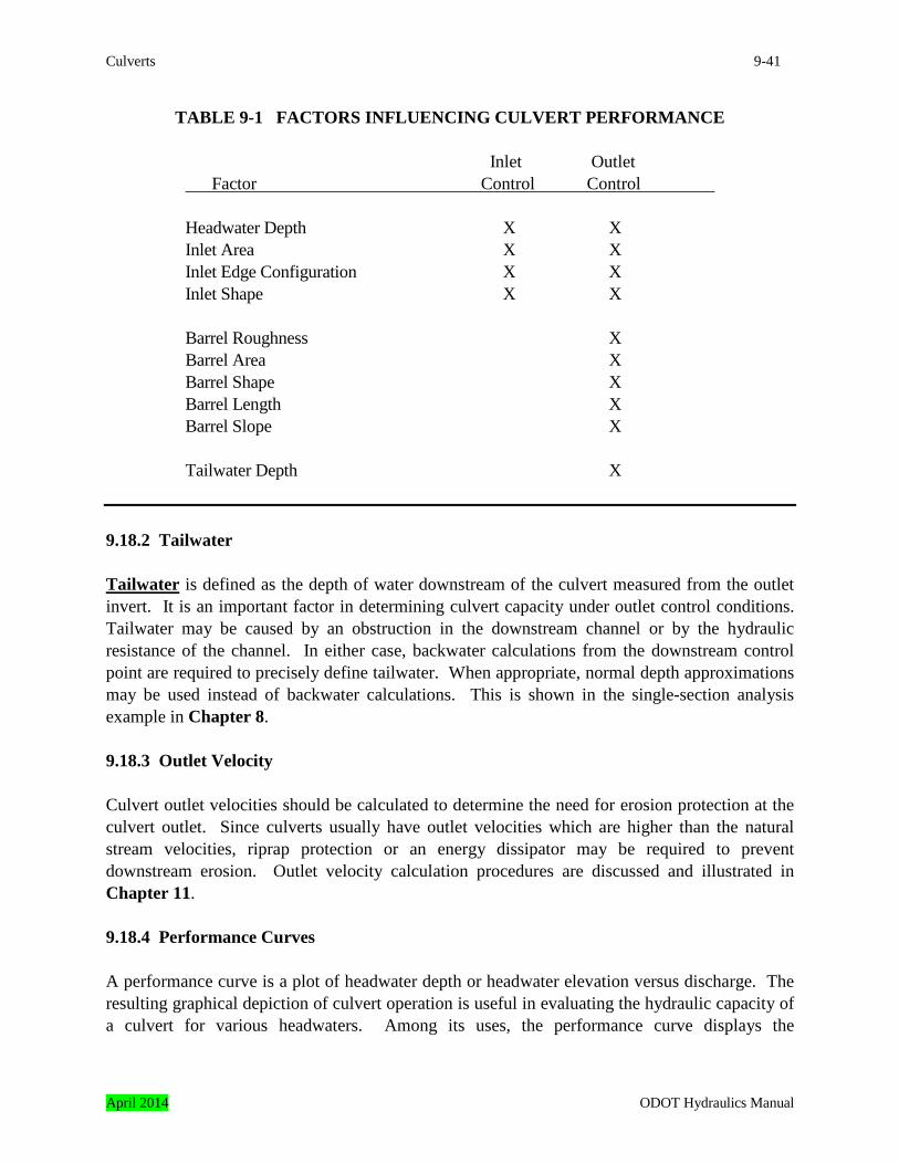
Culverts 9-41
TABLE 9-1 FACTORS INFLUENCING CULVERT PERFORMANCE
Inlet Outlet Factor Control Control Headwater Depth X X Inlet Area X X Inlet Edge Configuration X X Inlet Shape X X Barrel Roughness X Barrel Area X Barrel Shape X Barrel Length X Barrel Slope X Tailwater Depth X 9.18.2 Tailwater Tailwater is defined as the depth of water downstream of the culvert measured from the outlet invert. It is an important factor in determining culvert capacity under outlet control conditions. Tailwater may be caused by an obstruction in the downstream channel or by the hydraulic resistance of the channel. In either case, backwater calculations from the downstream control point are required to precisely define tailwater. When appropriate, normal depth approximations may be used instead of backwater calculations. This is shown in the single-section analysis example in Chapter 8. 9.18.3 Outlet Velocity Culvert outlet velocities should be calculated to determine the need for erosion protection at the culvert outlet. Since culverts usually have outlet velocities which are higher than the natural stream velocities, riprap protection or an energy dissipator may be required to prevent downstream erosion. Outlet velocity calculation procedures are discussed and illustrated in Chapter 11. 9.18.4 Performance Curves A performance curve is a plot of headwater depth or headwater elevation versus discharge. The resulting graphical depiction of culvert operation is useful in evaluating the hydraulic capacity of a culvert for various headwaters. Among its uses, the performance curve displays the
April 2014 ODOT Hydraulics Manual
9-42 Culverts
consequences of higher flow rates at the site and the benefits of inlet improvements. The determination of a performance curve should be routinely done as part of the hydraulic analysis. In developing a culvert performance curve, both inlet and outlet control curves must be calculated. This is necessary to determine the dominant control for a given discharge as control may shift from the inlet to the outlet, or vice-versa over a range of discharges. The overall performance curve reflects the controlling portions of the individual inlet control and outlet control curves. Figure 9-10 illustrates a typical culvert performance curve. At the design headwater, the culvert operates under inlet control. With inlet improvement the culvert performance can be increased to take better advantage of the culvert barrel capacity. 9.18.5 Culverts Flowing in Inlet Control Since the control is at the upstream end in inlet control, only the headwater and the inlet configuration affect the culvert performance (Table 9-1). The headwater depth is measured from the invert of the inlet control section to the surface of the upstream pool. The inlet area is the cross-sectional area of the face of the culvert. Generally, the inlet face area is the same as the barrel area, except for some types of improved inlets. The inlet edge configuration describes the entrance type. Some typical inlet edge configurations are thin edge projecting, mitered, square edges in a headwall, and beveled edge. The inlet shape is usually the same as the shape of the culvert barrel; however, it may be enlarged as in the case of a tapered inlet. Typical shapes are rectangular, circular, and elliptical. Whenever the inlet face is a different size or shape than the culvert barrel, the possibility of an additional control section within the barrel exists. An additional factor which influences inlet control performance is the barrel slope. The effect is small, however, and it can be ignored or a small slope correction factor can be inserted in the inlet control equations. The inlet edge configuration is a major factor in inlet control performance, and it can be modified to improve performance. As the inlet edge condition improves, the flow contraction at the inlet decreases. The reduced flow contraction increases inlet performance and allows more flow through the barrel for the same headwater. A method of increasing inlet performance is the use of beveled edges at the entrance of the culvert. Beveled edges reduce the contraction of the flow by effectively enlarging the face of the culvert. Although any beveling will improve the hydraulic efficiency, design charts are available for two bevel angles, 45 degrees and 33.7 degrees. 9.18.5.1 Inlet Control Examples Several different examples of inlet control are shown in Figure 9-11. The flow type depends on the degree of submergence of the inlet and outlet ends of the culvert. In all of these examples,
ODOT Hydraulics Manual April 2014

Culverts 9-43
the control section is at the inlet end. Depending on the tailwater, a hydraulic jump may occur downstream from the inlet. Figure 9-11a depicts a condition where neither the inlet nor the outlet ends are submerged. The flow passes through critical depth just downstream of the culvert entrance and the flow in the barrel is supercritical. The barrel flows partially full over its length and the flow approaches or has reached normal depth at the outlet end. Figure 9-11b shows that outlet submergence does not assure outlet control. In this case, the flow just downstream of the inlet is supercritical and a hydraulic jump forms in the culvert barrel.
April 2014 ODOT Hydraulics Manual
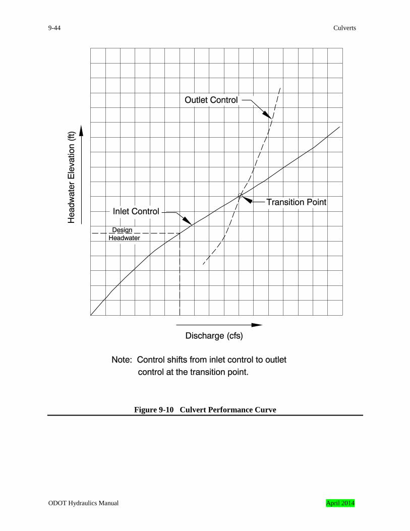
9-44 Culverts
Figure 9-10 Culvert Performance Curve
ODOT Hydraulics Manual April 2014
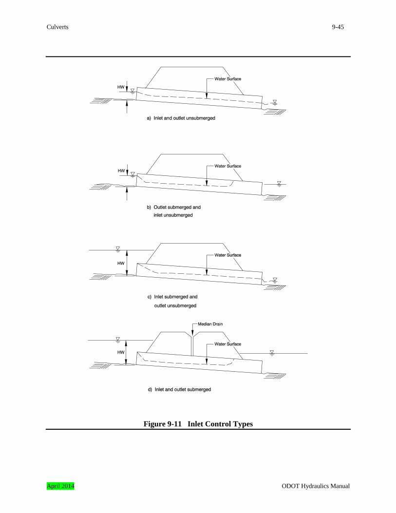
Culverts 9-45
Figure 9-11 Inlet Control Types
April 2014 ODOT Hydraulics Manual
9-46 Culverts
Figure 9-11c is a more typical design situation. The inlet end is submerged and the outlet end flows freely. Again, the flow is supercritical and the barrel flows partially full over its length. Critical depth is located just downstream of the culvert entrance, and the flow is approaching or has reached normal depth at the downstream end of the culvert. Figure 9-11d is an unusual condition illustrating the fact that even submergence of both the inlet and the outlet ends of the culvert does not assure full flow. In this case, a hydraulic jump will form in the barrel. The median inlet provides ventilation of the culvert barrel. If the barrel were not ventilated, sub-atmospheric pressures could develop which might create an unstable condition during which the barrel would alternate between full flow and partial flow. 9.18.5.2 Inlet Control Design Equations The equations used to develop the inlet control nomographs are based on two basic inlet headwater conditions. If the inlet is not submerged, it performs as a weir. If the inlet is submerged, it performs as an orifice. Equations for both conditions are in this subsection. Between the unsubmerged and the submerged conditions a transition zone exists where the equation results do not match. The zone is defined empirically by drawing a curve between and tangent to the curves defined by the unsubmerged and submerged equations. In most cases, the transition zone is short and the curve is easily constructed. FHWA Inlet Control Equations – The Federal Highway Administration has developed inlet control equations for many culvert shapes and inlet configurations. These equations are discussed in Hydraulic Engineering Series No. 5 “Hydraulic Design of Highway Culverts.” Equations 9-1a, 9-1b, and 9-1c are unsubmerged and submerged inlet control design equations, respectively. Note that there are two forms of the unsubmerged equation. Form (1) is based on the specific head at critical depth, adjusted with two correction factors. Form (2) is an exponential equation similar to a weir equation. Form (1) is preferable from a theoretical standpoint, but form (2) is easier to apply. Either form of unsubmerged inlet control equation will produce adequate results. The constants for the equations are given in Table 9-2. Table 9-2 provides the unsubmerged and submerged equation coefficients for each shape, material, and edge configuration. For the unsubmerged equations, the form of the equation is also noted.
ODOT Hydraulics Manual April 2014
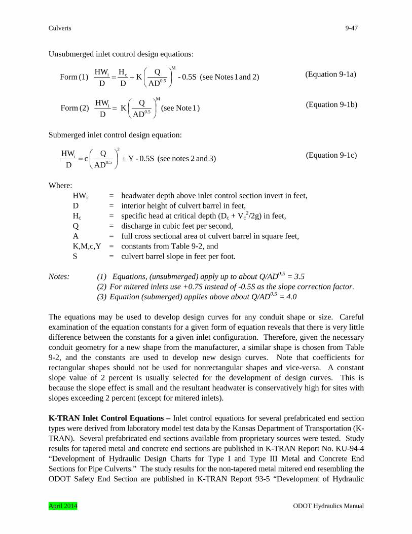
Culverts 9-47
Unsubmerged inlet control design equations:
(Equation 9-1a)
(Equation 9-1b)
Submerged inlet control design equation: (Equation 9-1c)
Where: HWi = headwater depth above inlet control section invert in feet, D = interior height of culvert barrel in feet, Hc = specific head at critical depth (Dc + Vc
2/2g) in feet, Q = discharge in cubic feet per second, A = full cross sectional area of culvert barrel in square feet, K,M,c,Y = constants from Table 9-2, and S = culvert barrel slope in feet per foot. Notes: (1) Equations, (unsubmerged) apply up to about Q/AD0.5 = 3.5
(2) For mitered inlets use +0.7S instead of -0.5S as the slope correction factor. (3) Equation (submerged) applies above about Q/AD0.5 = 4.0
The equations may be used to develop design curves for any conduit shape or size. Careful examination of the equation constants for a given form of equation reveals that there is very little difference between the constants for a given inlet configuration. Therefore, given the necessary conduit geometry for a new shape from the manufacturer, a similar shape is chosen from Table 9-2, and the constants are used to develop new design curves. Note that coefficients for rectangular shapes should not be used for nonrectangular shapes and vice-versa. A constant slope value of 2 percent is usually selected for the development of design curves. This is because the slope effect is small and the resultant headwater is conservatively high for sites with slopes exceeding 2 percent (except for mitered inlets). K-TRAN Inlet Control Equations – Inlet control equations for several prefabricated end section types were derived from laboratory model test data by the Kansas Department of Transportation (K-TRAN). Several prefabricated end sections available from proprietary sources were tested. Study results for tapered metal and concrete end sections are published in K-TRAN Report No. KU-94-4 “Development of Hydraulic Design Charts for Type I and Type III Metal and Concrete End Sections for Pipe Culverts.” The study results for the non-tapered metal mitered end resembling the ODOT Safety End Section are published in K-TRAN Report 93-5 “Development of Hydraulic
2) and 1 Notes (see 0.5S - AD
QK DH
DHW (1) Form
M
0.5ci
+=
) 1 Note (seeAD
QK D
HW (2) FormM
0.5i
=
3) and 2 notes (see 0.5S - Y AD
Q c D
HW 2
0.5i +
=
April 2014 ODOT Hydraulics Manual

9-48 Culverts
Design Charts for Type IV End Section for Pipe Culverts.” The equation variables are the same as those described previously for the FHWA equations, with one addition, as follows: g = gravitational acceleration, 32.2 feet per second squared The tapered and mitered prefabricated concrete end section is shown on Figure 9-12 with the dimensions of the largest and smallest end sections tested by K-TRANS. The inlet control equations are as follows:
(Equation 9-2a)
(Equation 9-2b)
(Equation 9-2c)
Note: ≤ (Less than or equal to) ≥ (Greater than or equal to) The tapered and mitered prefabricated metal end section is shown on Figure 9-13 with the dimensions of the largest and smallest end sections tested. The inlet control equations follow:
(Equation 9-3a)
(Equation 9-3b)
(Equation 9-3c)
0.42 gDQ 0when
gDQ 1.53
DHW
5
5i
0.55
≤
≤
=
0.68 gDQ 0.42 when 0.055
gDQ 2.13
DHW
5
5i ≤
<+
=
1.30 gDQ 0.68 when
gDQ 2.50
gDQ 1.50 - 1.367
DHW
55
5i
2
≤
<
+
=
0.41 gDQ 0 when
gDQ 1.60
DHW
5
0.60
5i ≤
≤
=
0.62 gDQ 0.41 when 0.023
gDQ 2.23
DHW
55i ≤
<+
=
1.20 gDQ 0.62 when
gDQ 2.90
gDQ 1.61 - 1.289
DHW
55
5i
2
≤
<
+
=
ODOT Hydraulics Manual April 2014

Culverts 9-49
Ten mitered prefabricated metal safety end sections of different sizes, safety bar configurations, and miter slopes were tested. The miter slopes were 1V: 4H and 1V: 6H. The safety end sections shown on ODOT Standard Drawings RD322 and RD324 are typical of the end sections tested. The study developed the following inlet control equations for safety end sections with safety bars.
≤ 0.42 (Equation 9-4a)
(Equation 9-4b)
The preceding inlet control equations were developed with unobstructed inlet sections. ODOT design practice is to use the hydraulic properties of unobstructed sections in design. The safety end sections were also tested by K-TRANS with varying amounts of debris obstruction. The hydraulic performance equations and conclusions are in K-TRANS Report KU-93-5.
= 5
0.60
5i
gDQ when
gDQ 1.69
DHW
0.42 gDQ when
gDQ 4
gDQ 1.93 - 1.11
DHW
5
2
55i >
+
=
April 2014 ODOT Hydraulics Manual
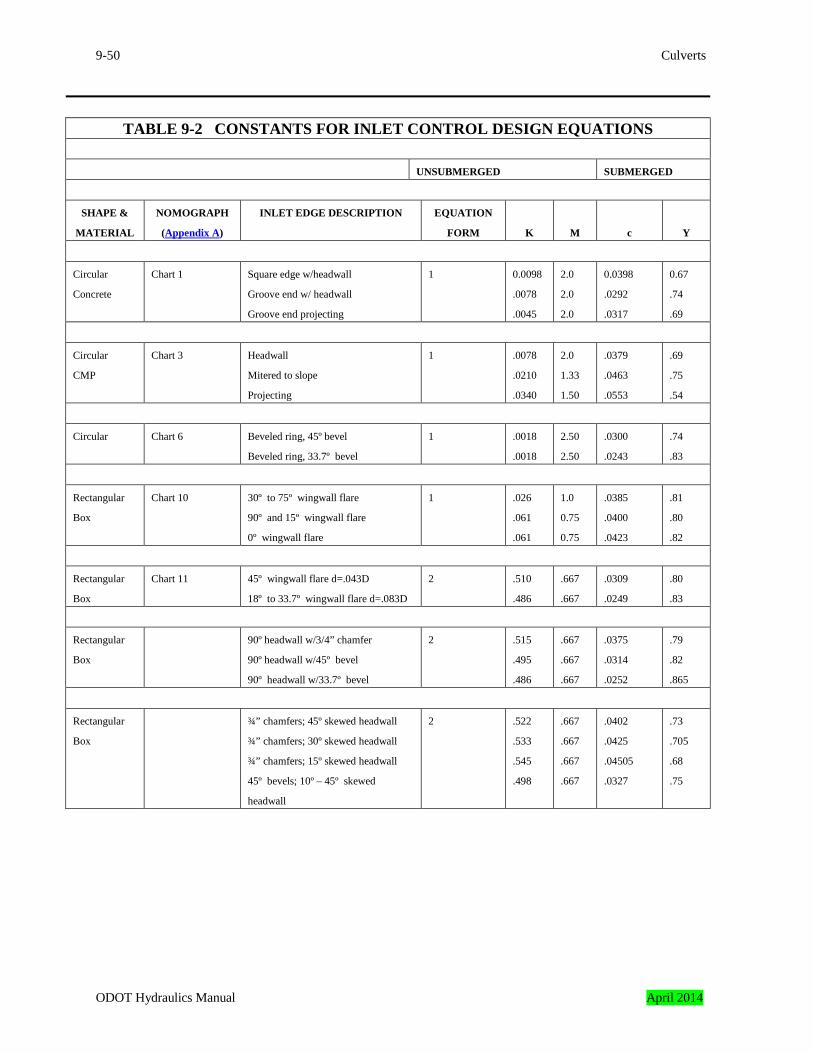
9-50 Culverts
TABLE 9-2 CONSTANTS FOR INLET CONTROL DESIGN EQUATIONS
UNSUBMERGED SUBMERGED
SHAPE &
MATERIAL
NOMOGRAPH
(Appendix A)
INLET EDGE DESCRIPTION EQUATION
FORM
K
M
c
Y
Circular
Concrete
Chart 1 Square edge w/headwall
Groove end w/ headwall
Groove end projecting
1 0.0098
.0078
.0045
2.0
2.0
2.0
0.0398
.0292
.0317
0.67
.74
.69
Circular
CMP
Chart 3 Headwall
Mitered to slope
Projecting
1 .0078
.0210
.0340
2.0
1.33
1.50
.0379
.0463
.0553
.69
.75
.54
Circular Chart 6 Beveled ring, 45º bevel
Beveled ring, 33.7º bevel
1 .0018
.0018
2.50
2.50
.0300
.0243
.74
.83
Rectangular
Box
Chart 10 30º to 75º wingwall flare
90º and 15º wingwall flare
0º wingwall flare
1 .026
.061
.061
1.0
0.75
0.75
.0385
.0400
.0423
.81
.80
.82
Rectangular
Box
Chart 11 45º wingwall flare d=.043D
18º to 33.7º wingwall flare d=.083D
2 .510
.486
.667
.667
.0309
.0249
.80
.83
Rectangular
Box
90º headwall w/3/4” chamfer
90º headwall w/45º bevel
90º headwall w/33.7º bevel
2 .515
.495
.486
.667
.667
.667
.0375
.0314
.0252
.79
.82
.865
Rectangular
Box
¾” chamfers; 45º skewed headwall
¾” chamfers; 30º skewed headwall
¾” chamfers; 15º skewed headwall
45º bevels; 10º – 45º skewed
headwall
2 .522
.533
.545
.498
.667
.667
.667
.667
.0402
.0425
.04505
.0327
.73
.705
.68
.75
ODOT Hydraulics Manual April 2014
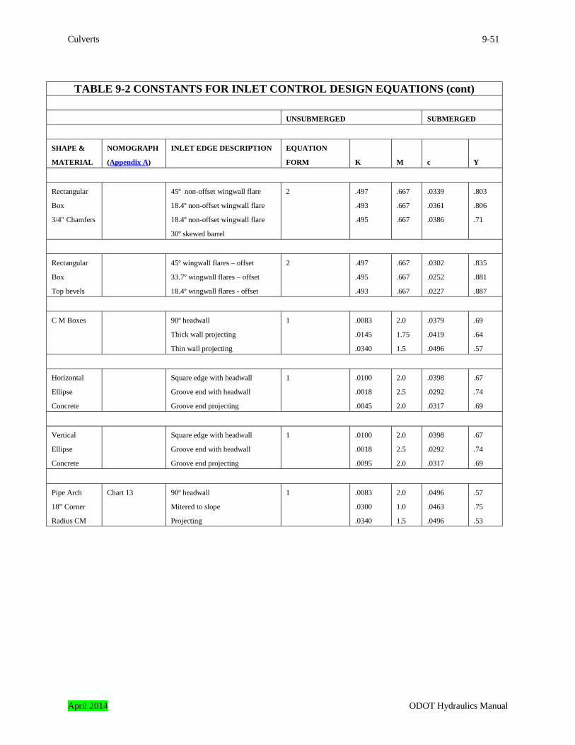
Culverts 9-51
TABLE 9-2 CONSTANTS FOR INLET CONTROL DESIGN EQUATIONS (cont)
UNSUBMERGED SUBMERGED
SHAPE &
MATERIAL
NOMOGRAPH
(Appendix A)
INLET EDGE DESCRIPTION EQUATION
FORM
K
M
c
Y
Rectangular
Box
3/4" Chamfers
45º non-offset wingwall flare
18.4º non-offset wingwall flare
18.4º non-offset wingwall flare
30º skewed barrel
2 .497
.493
.495
.667
.667
.667
.0339
.0361
.0386
.803
.806
.71
Rectangular
Box
Top bevels
45º wingwall flares – offset
33.7º wingwall flares – offset
18.4º wingwall flares - offset
2 .497
.495
.493
.667
.667
.667
.0302
.0252
.0227
.835
.881
.887
C M Boxes 90º headwall
Thick wall projecting
Thin wall projecting
1 .0083
.0145
.0340
2.0
1.75
1.5
.0379
.0419
.0496
.69
.64
.57
Horizontal
Ellipse
Concrete
Square edge with headwall
Groove end with headwall
Groove end projecting
1 .0100
.0018
.0045
2.0
2.5
2.0
.0398
.0292
.0317
.67
.74
.69
Vertical
Ellipse
Concrete
Square edge with headwall
Groove end with headwall
Groove end projecting
1 .0100
.0018
.0095
2.0
2.5
2.0
.0398
.0292
.0317
.67
.74
.69
Pipe Arch
18” Corner
Radius CM
Chart 13 90º headwall
Mitered to slope
Projecting
1 .0083
.0300
.0340
2.0
1.0
1.5
.0496
.0463
.0496
.57
.75
.53
April 2014 ODOT Hydraulics Manual
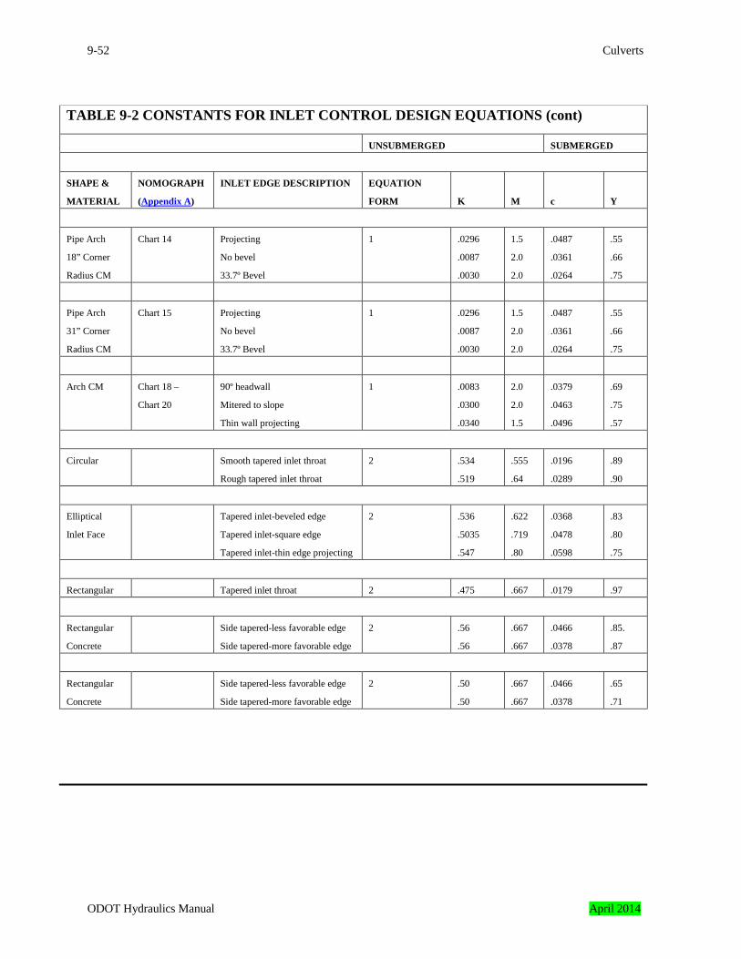
9-52 Culverts
TABLE 9-2 CONSTANTS FOR INLET CONTROL DESIGN EQUATIONS (cont)
UNSUBMERGED SUBMERGED
SHAPE &
MATERIAL
NOMOGRAPH
(Appendix A)
INLET EDGE DESCRIPTION EQUATION
FORM
K
M
c
Y
Pipe Arch
18” Corner
Radius CM
Chart 14 Projecting
No bevel
33.7º Bevel
1 .0296
.0087
.0030
1.5
2.0
2.0
.0487
.0361
.0264
.55
.66
.75
Pipe Arch
31” Corner
Radius CM
Chart 15 Projecting
No bevel
33.7º Bevel
1 .0296
.0087
.0030
1.5
2.0
2.0
.0487
.0361
.0264
.55
.66
.75
Arch CM Chart 18 –
Chart 20
90º headwall
Mitered to slope
Thin wall projecting
1 .0083
.0300
.0340
2.0
2.0
1.5
.0379
.0463
.0496
.69
.75
.57
Circular Smooth tapered inlet throat
Rough tapered inlet throat
2 .534
.519
.555
.64
.0196
.0289
.89
.90
Elliptical
Inlet Face
Tapered inlet-beveled edge
Tapered inlet-square edge
Tapered inlet-thin edge projecting
2 .536
.5035
.547
.622
.719
.80
.0368
.0478
.0598
.83
.80
.75
Rectangular Tapered inlet throat 2 .475 .667 .0179 .97
Rectangular
Concrete
Side tapered-less favorable edge
Side tapered-more favorable edge
2 .56
.56
.667
.667
.0466
.0378
.85.
.87
Rectangular
Concrete
Side tapered-less favorable edge
Side tapered-more favorable edge
2 .50
.50
.667
.667
.0466
.0378
.65
.71
ODOT Hydraulics Manual April 2014
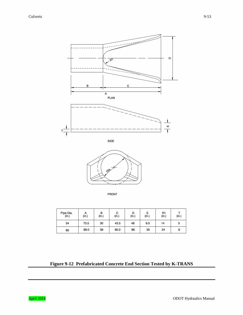
Culverts 9-53
Figure 9-12 Prefabricated Concrete End Section Tested by K-TRANS
April 2014 ODOT Hydraulics Manual
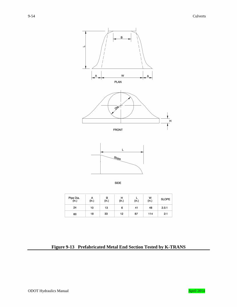
9-54 Culverts
Figure 9-13 Prefabricated Metal End Section Tested by K-TRANS
ODOT Hydraulics Manual April 2014

Culverts 9-55
9.18.5.3 Inlet Control Nomographs Inlet control nomographs for many culverts are included in Appendix A. These nomographs are sufficiently accurate for most design purposes. They are not, however, as accurate as the equations. In formulating inlet and outlet control design nomographs in Appendix A, a certain degree of error is introduced into the design process. This error is due to the fact that the nomograph construction involves graphical fitting techniques resulting in scales which do not exactly match the equations. Most of the nomographs are from FHWA publications. They have precisions of ±10 percent of the equation values in terms of headwater (inlet control) or head loss (outlet control). The inlet control nomographs for the prefabricated concrete and metal end sections, and the safety end section were developed by ODOT based on the K-TRANS equations listed previously in this chapter. Their precision is estimated to be ± 10 percent. The aluminum structural plate conduit nomographs were provided by Kaiser Aluminum, and their precision is estimated to be ±5 percent. Instructions for Use
1. To determine headwater (HW); given Q, and size and type of culvert.
a. Connect with a straightedge the given culvert diameter or height, D and the
discharge, Q, or Q/B for box culverts; mark intersection of straightedge on HW/D scale marked (1).
b. If HW/D scale marked (1) represents entrance type used, read HW/D on scale (1).
If another of the three entrance types listed on the nomograph is used, extend the point of intersection in (a) horizontally to scale (2) or (3) and read HW/D.
c. Compute HW by multiplying HW/D by D.
2. To determine Discharge (Q) per barrel; given HW, and size and type of culvert.
a. Compute HW/D for given conditions.
b. Locate HW/D on scale for appropriate entrance type. If scale (2) and (3) is used, extend HW/D point horizontally to scale (1).
c. Connect point on HW/D scale (1) as found in (b) above and the size of culvert on
the left scale. Read Q or Q/B on the discharge scale. d. If Q/B is read in (c) multiply by B (span of box culvert) to find Q.
3. To determine culvert size; given Q, allowable HW and type of culvert.
April 2014 ODOT Hydraulics Manual
9-56 Culverts
a. Using a trial size, compute HW/D. b. Locate HW/D on scale for appropriate entrance type. If scale (2) or (3) is used,
extend HW/D point horizontally to scale (1).
c. Connect point on HW/D scale (1) as found in (b) above to given discharge and read diameter, height, or size of culvert required for HW/D value.
d. If D is not that originally assumed, repeat procedure with a new D.
9.19 Culverts Flowing in Outlet Control All factors influencing culvert performance in inlet control also influence culverts in outlet control. In addition, the barrel characteristics (roughness, area, shape, length, and slope) and the tailwater elevation affect culvert performance in outlet control (Table 9-1). The barrel roughness is a function of the material used to fabricate the barrel. Typical materials include concrete and corrugated metal. The roughness is represented by a hydraulic resistance coefficient such as the Manning “n” value. Typical Manning “n” values for culverts are presented in Chapter 8, Appendix A. The barrel area and barrel shape are self-explanatory. The barrel length is the length of the full barrel section from the entrance to the exit of the culvert. Because the design height of the barrel and the slope influence the actual length, an approximation of barrel length is usually necessary to begin the design process. The barrel slope is the actual slope of the culvert barrel. The barrel slope is often the same as the natural stream slope. The tailwater elevation is based on the downstream water surface elevation. Backwater calculations from a downstream control, a normal depth approximation, or field observations are used to define the tailwater elevation.
ODOT Hydraulics Manual April 2014
Culverts 9-57
9.19.1 Outlet Control Examples Various outlet control flow conditions are illustrated in Figure 9-14. The control section is at the outlet end of the culvert or further downstream in all cases. The flow in the barrel is subcritical for the partial flow situations. Condition 9-14a represents the classic full flow condition, with both inlet and outlet submerged. The barrel is in pressure flow throughout its length. This condition is often assumed in calculations, but seldom actually exists. Condition 9-14b depicts the outlet submerged with the inlet unsubmerged. For this case, the headwater depth is shallow so that the inlet crown is exposed as the flow contracts into the culvert. Condition 9-14c shows the entrance submerged to such a degree that the culvert flows full throughout its entire length while the exit is unsubmerged. This is a rare condition. It requires an extremely high headwater to maintain full barrel flow with no tailwater. The outlet velocities are usually high under this condition. Critical depth must equal the barrel height for this flow condition to occur. Condition 9-14d is more typical. The culvert entrance is submerged by the headwater and the outlet end flows freely with a low tailwater. For this condition, the barrel flows partially full over at least part of its length (subcritical flow) and the flow passes through critical depth just upstream of the outlet. Condition 9-14e is also typical, with neither the inlet nor the outlet end of the culvert submerged. The barrel flows partially full over its entire length and the flow profile is subcritical. 9.19.2 Outlet Control Hydraulics This section provides a method to accurately determine headwater depth for culverts flowing full as depicted in Figures 9-14a, 9-14b, and 9-14c. The procedure gives an approximate solution for a free water surface condition throughout the barrel length as shown in Figure 9-14e, or full barrel flow over part of its length as shown in Figure 9-14d. An exact solution to these flow conditions requires calculating the water surface profile through the culvert barrel.
April 2014 ODOT Hydraulics Manual
9-58 Culverts
Figure 9-14 Outlet Control Types
ODOT Hydraulics Manual April 2014

Culverts 9-59
Outlet control flow conditions are calculated based on the principle of conservation of energy. The total energy (HL) required to pass the flow through the culvert barrel is shown in Figure 9-15 and expressed in Equation 9-5. It is made up of three major components. These components are usually expressed in feet of water (head) and include the entrance loss, the friction loss through the barrel, and the exit loss. Other losses, such as bend losses and junction losses, should be included as appropriate. HL = He + Hf + Ho + Hb + Hj (Equation 9-5) Where: HL = total energy head in feet, He = entrance loss in feet, Hf = friction loss through the barrel in feet, Ho = exit loss in feet, Hb = bend loss in feet, and Hj = junction loss in feet. The entrance loss is a function of the velocity head in the barrel (V2/2g) times an entrance loss coefficient Ke. Values of Ke based on various inlet configurations are given in Table 9-3.
(Equation 9-6)
Where: Ke = entrance loss coefficient, V = velocity of full flow in the culvert barrel in feet per second, and g = gravitational acceleration, 32.2 feet per second squared. The friction loss in the barrel is also a function of the velocity head. Based on the Manning equation, the friction loss is:
(Equation 9-7)
Where: n = Manning roughness coefficient (Chapter 8 Appendix A), L = length of the culvert barrel in feet,
2gV K H
2
ee =
=
2gV
RL29n H
2
1.33
2
f
April 2014 ODOT Hydraulics Manual
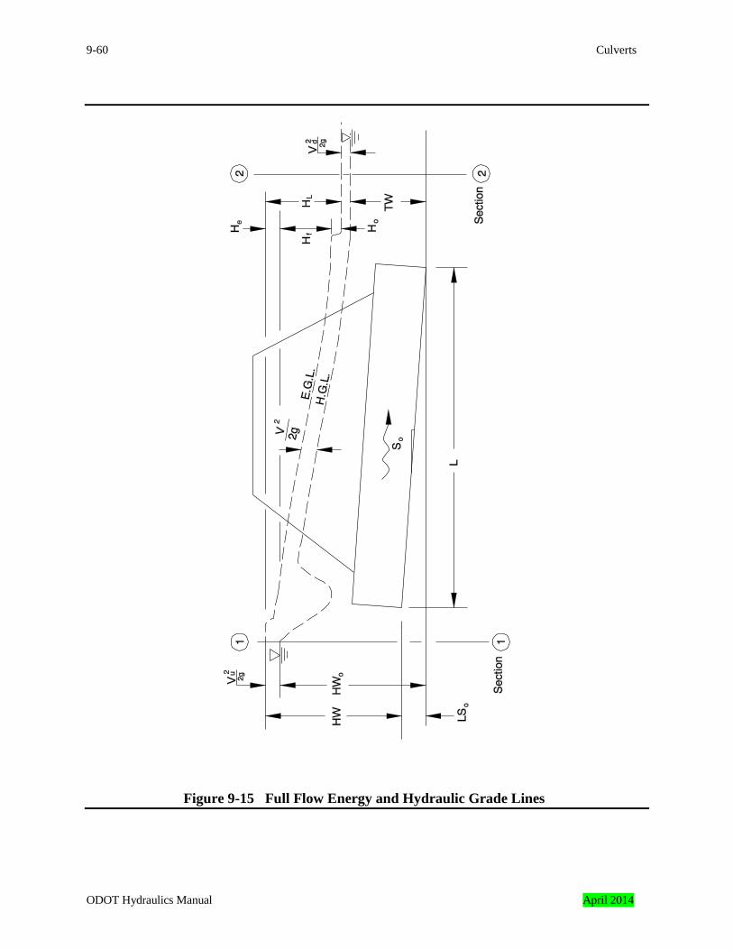
9-60 Culverts
Figure 9-15 Full Flow Energy and Hydraulic Grade Lines
ODOT Hydraulics Manual April 2014

Culverts 9-61
TABLE 9-3 ENTRANCE LOSS COEFFICIENTS
Outlet control, full or partially full entrance head loss He = Ke (V2/2g)
Type of Structure and Design of Entrance Coefficient Ke
Pipe, Concrete Projecting from fill, socket end (groove-end) . . . . . . . . . . . . . . . . . . . . . . . . . . . . . . . . . . . . . . . . 0.2 Projecting from fill, square cut end . . . . . . . . . . . . . . . . . . . . . . . . . . . . . . . . . . . . . . .. . . . . . . . . . 0.5 Headwall or headwall and wingwalls Socket end of pipe (groove end) . . . . . . . . . . . . . . . . . . . . . . . . . . . . . . . . . . . . . . . . . . . . . . . 0.2 Square-edge . . . . . . . . . . . . . . . . . . . . . . . . . . . . . . . . . . . . . . . . . . . . . . . . . . . . . . . . . . . . . . . 0.5 Rounded (radius = 1/12D) . . . . . . . . . . . . . . . . . . . . . . . . . . . . . . . . . . . . . . . . . . . . . . . . . . . . 0.2 Mitered to conform to fill slope . . . . . . . . . . . . . . . . . . . . . . . . . . . . . . . . . . . . . . . . . . . . . . . . . . . . 0.7 * End section conforming to fill slope . . . . . . . . . . . . . . . . . . . . . . . . . . . . . . . . . . . . . . . . . . . . . . . . 0.5 End section conforming to fill slope (see Figure 9-12), dia ≤ 54 in. . . . . . . . . . . . . . . . . . . . . 0.35 End section conforming to fill slope (see Figure 9-12), dia > 60 in. 0.30 Beveled edges, 33.7º or 45º bevels . . . . . . . . . . . . . . . . . . . . . . . . . . . . . . . . . . . . . . . . . . . . . . . . . 0.2 Side- or slope-tapered inlet . . . . . . . . . . . . . . . . . . . . . . . . . . . . . . . . . . . . . . . . . . . . . . . . . . . . . . . 0.2 Pipe, or Pipe-Arch, Corrugated Metal Projecting from fill (no headwall) . . . . . . . . . . . . . . . . . . . . . . . . . . . . . . . . . . . . . . . . . . . . . . . . . . 0.9 Headwall or headwall and wingwalls square-edge . . . . . . . . . . . . . . . . . . . . . . . . . . . . . . . . . . . . . 0.5 Mitered to conform to fill slope, paved or unpaved slope . . . . . . . . . . . . . . . . . . . . . . . . . . . . . . . . 0.7 * End section conforming to fill slope . . . . . . . . . . . . . . . . . . . . . . . . . . . . . . . . . . . . . . . . . . . . . . . . 0.5 End section conforming to fill slope (see Figure 9-13), dia ≤ 54 in. . . . . . . . . . . . . . . . . . . . 0.35 End section conforming to fill slope (see Figure 9-13), dia > 60 in. . . . . . . . . . . . . . . . . . . . . 0.30 Safety end section with safety bars, dia = 24 in . . . . . . . . . . . . . . . . . . . . . . . . . . . . . . . . . . . . 0.65 Safety end section with safety bars, dia = 60 in . . . . . . . . . . . . . . . . . . . . . . . . . . . . . . . . . . 0.85 Beveled edges, 33.7º or 45º bevels . . . . . . . . . . . . . . . . . . . . . . . . . . . . . . . . . . . . . . . . . . . . . . . . . 0.2 Side- or slope-tapered inlet . . . . . . . . . . . . . . . . . . . . . . . . . . . . . . . . . . . . . . . . . . . . . . . . . . . . . . . 0.2 Box, Reinforced Concrete Headwall parallel to embankment (no wingwalls) Square-edged on 3 edges . . . . . . . . . . . . . . . . . . . . . . . . . . . . . . . . . . . . . . . . . . . . . . . . . . . . . 0.5 Rounded on 3 edges to radius of 1/12 barrel dimension, or beveled edges on 3 sides. . 0.2 Wingwalls at 30º to 75º to barrel Square-edged at crown . . . . . . . . . . . . . . . . . . . . . . . . . . . . . . . . . . . . . . . . . . . . . . . . . . . . . . . 0.4 Crown edge rounded to radius of 1/12 barrel dimension, or beveled top edge . . . . . . . . . . . . 0.2 Wingwall at 10º to 25º to barrel Square-edged at crown . . . . . . . . . . . . . . . . . . . . . . . . . . . . . . . . . . . . . . . . . . . . . . . . . . . . . . . 0.5 Wingwalls parallel (extension of sides) Square-edged at crown . . . . . . . . . . . . . . . . . . . . . . . . . . . . . . . . . . . . . . . . . . . . . . . . . . . . . . . 0.7 Side- or slope-tapered inlet . . . . . . . . . . . . . . . . . . . . . . . . . . . . . . . . . . . . . . . . . . . . . . . . . . . . . . . 0.2 * Note: “End Section conforming to fill slope,” made of either metal or concrete, are the sections commonly
available from manufacturers. Limited hydraulic tests indicate they are equivalent in operation to a headwall in both inlet and outlet control.
April 2014 ODOT Hydraulics Manual
9-62 Culverts
Figure 9-16 Bend Loss Coefficients
ODOT Hydraulics Manual April 2014
Culverts 9-63
H 2gV
L29nKK1 H
21.33
2e
L +
+++= R
R = hydraulic radius of the full culvert barrel, A/P, in feet (Chapter 8 Appendix B), A = full cross-sectional area of the barrel in square feet (Chapter 8 Appendix B), and P = wetted perimeter of the full barrel in feet (Chapter 8 Appendix B). The exit loss is a function of the change in velocity heads between the outlet of the culvert barrel and the downstream channel. For a sudden expansion such as an endwall, the exit loss is:
(Equation 9-8)
Where: Vd = channel velocity downstream of the culvert in feet per second The downstream velocity is usually neglected, in which case the exit loss is equal to the full flow velocity head in the barrel. This depicts the case of a culvert discharging into a pool. The outlet loss equation based on this assumption is:
(Equation 9-9)
Bend losses are also a function of velocity head in the culvert barrel and a bend loss coefficient Kb. Values of Kb are obtained from Figure 9-16. To determine Kb, first determine the bend coefficient for a 90º bend from Figure 9-16a, and then apply the appropriate adjustment factor from Figure 9-16b. Bend losses can be calculated using the following equation:
(Equation 9-10)
Where: Kb = bend loss coefficient Junction losses are considered where appropriate. Examples of junctions and methods to calculate junction losses are described in Chapter 13. Usually it is assumed the pipes entering and leaving the junction are full when calculating junction losses for outlet control. Inserting the above relationships for entrance loss, friction loss, bend loss and exit loss into Equation 9-5, the following equation for head loss is obtained:
(Equation 9-11)
=
2gV
- 2gV 1.0 H
2d
2
o
2gV 1.0 H
2
o =
2gV K H
2
bb =
April 2014 ODOT Hydraulics Manual

9-64 Culverts
2gV
L29nK1 H
21.33
2e
L
++= R
Since most culverts have no bend or junction losses, the equation can be reduced to:
(Equation 9-12)
Figure 9-15 shows the energy grade line and the hydraulic grade line for full flow in a culvert barrel. The energy grade line represents the total energy at any point along the culvert barrel. HW is the depth from the inlet invert to the energy grade line. The hydraulic grade line is the depth to which water would rise in vertical tubes connected to the sides of the culvert barrel. In full flow, the energy grade line and the hydraulic grade line are parallel straight lines separated by the velocity head except in the vicinity of the inlet where the flow passes through a contraction. The headwater and tailwater condition as well as the entrance, friction, and exit losses are also shown in Figure 9-15. Equating the total energy at sections 1 and 2, upstream and downstream of the culvert barrel, the following relationship results:
(Equation 9-13)
Where: HWo = headwater depth above the outlet invert in feet, Vu = approach velocity in feet per second, TW = tailwater depth above the outlet invert in feet, Vd = channel velocity downstream of the culvert in feet per second, and HL = sum of all losses in feet. In most cases the approach velocity (Vu) and the downstream velocity (Vd) can be neglected. This depicts the case of a culvert discharging from pool to pool. When the upstream and downstream velocity head are assumed to be zero, the hydraulic gradeline and energy gradeline at Section 1 and Section 2 are coincident. Equation 9-13 then reduces to: HWo = TW + HL (Equation 9-14)
When the approach velocity (Vu) is assumed to be zero HWo = HW + (L)(S) (Equation 9-15) Where: S = barrel slope in feet per foot
L
2d
2u
o H 2gV
TW 2gV
HW ++=+
ODOT Hydraulics Manual April 2014
Culverts 9-65
Substituting Equation 9-15 into Equation 9-14, the equation for headwater depth, HW, becomes HW = TW + HL – (L)(S) (Equation 9-16) If it is desired to include the approach and/or downstream velocities, use Equation 9-8 for exit losses and Equation 9-13 instead of Equation 9-16 to calculate the headwater. To accurately determine the headwater depth for the conditions shown in Figure 9-14d and 9-14e, the water surface profile through the culvert barrel must be calculated. Fortunately an approximate method of computation is available as explained below. The approximate method gives satisfactory results for headwater depths above 0.75D, where D is the height of culvert barrel. For the condition shown in Figure 9-14d, the culvert must flow full for part of its length. The hydraulic gradeline for the portion of the length in full flow will pass through a point where the water breaks with the top of the culvert as represented by point A in Figure 9-14d. Backwater computations show that the hydraulic gradeline, if extended as a straight line, will cut the plane of the outlet cross section at a point above critical depth (water surface). This point is at a height approximately equal to one half the distance between critical depth and the crown of the culvert [(dc+D)/2]. The elevation of this point can be used as an equivalent hydraulic gradeline; and HL, as determined by Equation 9-12 or the nomographs, can be added to this elevation to find the water surface elevation of the headwater pool. The full flow conditions for part of the barrel length, Figure 9-14d, will exist when: the headwater depth HW is equal to or greater than the quantity:
(Equation 9-17)
Where: HW = headwater depth in feet, V = velocity of full flow in the culvert barrel in feet per second, Ke = entrance loss coefficient, and D = inside height of the culvert in feet. If the headwater is less than the above value, a free water surface as shown in Figure 9-14e, will extend through the culvert barrel. Headwater depth HW can be expressed by a common equation for all outlet-control conditions, including all depths of tailwater. This is accomplished by designating the vertical dimension from the culvert invert at the outlet to the elevation from which H is measured as ho. The headwater depth HW equation is:
++≥
2gV )K (1 D HW
2
e
April 2014 ODOT Hydraulics Manual

9-66 Culverts
HW = HL + ho – (L)(S) (Equation 9-18) Where: HL = sum of all losses in feet computed by Equation 9-12 or from the nomographs, ho = tailwater depth or (dc+D)/2, in feet, which ever is greater (see Note), L = length of the culvert barrel in feet, and S = barrel slope in feet per foot. Note: ho will equal the tailwater depth for conditions shown in Figure 9-14a, 9-14b, and 9-14c.
ho will either equal the tailwater depth or (dc+D)/2, whichever is greater, for the conditions shown in Figure 9-14d and 9-14e.
9.19.3 Outlet Control Nomographs Outlet control nomographs solve the equation
for head H when the culvert barrel flows full for its entire length. They are also used to determine head H for some part-full flow conditions with outlet control. These nomographs do not give a complete solution for finding headwater HW, since they only give HL as calculated in Equation 9-12. Headwater is calculated by incorporating H into Equation 9-18, as follows: HW = HL + ho – (L)(S) (see discussion for “Outlet Control Hydraulics”). Instructions for Use
1.0 To determine head H given a culvert size and a discharge Q.
a. Locate the appropriate nomograph in Appendix A for the type of culvert selected. Find Ke for the entrance type in Table 9-3. Determine culvert barrel Manning’s “n” value using Chapter 8 Appendix A or methods in Chapter 8.
b. Begin in nomograph solution by locating the starting point on the length scale.
To locate the proper starting point on the length scales, follow the instructions below:
(1) If the n value of the nomograph corresponds to that of the culvert being
used, select the length curve for the proper Ke and locate the starting point at the given culvert length. If a Ke curve is not shown for the selected Ke, see (2) below. If the n value for the culvert selected differs from that of the nomograph, see (3) below.
++=
2gV
R L29nK1 H
2
1.33
2
e
ODOT Hydraulics Manual April 2014

Culverts 9-67
(2) For the n of the nomograph and a Ke intermediate between the scales
given, connect the given length on adjacent scales by a straight line and select a point on this line spaced between the two chart scales in proportion to the Ke values.
(3) For a different roughness coefficient (n1) than that of the chart n, use the
length scales shown with an adjusted length L1, calculated by the formula:
c. Using a straightedge, connect the point on the length scale to the size of the culvert barrel and mark the point of crossing on the “turning line”. See Instruction 2.0 for size considerations for a rectangular box culvert.
d. Pivot the straightedge on this point on the turning line and connect with the
discharge. Read the head in feet on the head (H) scale. For values beyond the limit of the chart scales, find H by solving Equation 9-12.
2.0 To use the box culvert nomograph for full-flow for other than square boxes.
a. Compute the cross-sectional area of the rectangular box.
b. Connect the proper point (see instruction 1.0) on the length scale to the barrel area and mark the point on the turning line. See Note.
Note: The area scale on the nomograph is calculated for barrel cross-sections with span B twice the height D; its close correspondence with area of square boxes assures it may be used for all sections intermediate between square and B = 2D or B = 1/2D. For other box proportions, use Equation 9-12 for more accurate results.
c. Pivot the straightedge on this point on the turning line and connect with the discharge. Read the head in feet on the head (H) scale.
9.19.4 Critical Depth Critical Depth (dc) can be determined by using the mathematical equations in Chapter 8 or by the critical depth charts in Chapter 8 Appendix B. Critical depth should never be greater than the diameter of the pipe or the rise of the box.
21
1 nnL L
=
April 2014 ODOT Hydraulics Manual
9-68 Culverts
9.20 Procedure for Selection of Culvert Size
Step 1: List the following data on the Culvert Design Sheet (Appendix B). a. The hydrological data which includes the method used to compute the peak flow,
the drainage area, the natural stream slope, the natural channel shape, the design flood and the check flood.
b. The allowable headwater depth, in feet, as discussed in Section 9.17. c. The inlet and outlet elevations in feet. d. The barrel slope in feet per foot. e. The approximate barrel length in feet. f. The type of culvert for first trial selection, including barrel material, barrel cross-
sectional shape and entrance type. Step 2: Determine the first trial size culvert. Since the procedure given is one of trial and error, the initial trial size can be
determined in several ways: a. by arbitrary selection, b. by using an approximating equation such as Q/10 = A (where A = end area) from
which the trial culvert dimensions are determined, or c. by using inlet control nomographs for the culvert type selected. If this method is
used, an HW/D must be assumed, say HW/D = 1.5, and using the given Q, a trail size is determined.
If any trial size is too large in dimension because of limited height of embankment or availability of size, multiple culverts may be used by dividing the discharge equally between the number of barrels used. Raising the embankment height or the use of pipe-arch and box culverts with width greater than height should be considered. Final selection should be based on an economic analysis.
ODOT Hydraulics Manual April 2014
Culverts 9-69
Step 3: Find headwater depth for trial size culvert. a. Assuming INLET CONTROL i. Using the trial size from Step 2, find the headwater depth (HW) by use of the
appropriate inlet control nomograph. Tailwater (TW) conditions are to be neglected in this determination. HW in this case is found by multiplying HW/D obtained from the nomographs by the height of culvert D.
ii. If HW is greater or less than allowable, try another trial size until HW is
acceptable for inlet control before computing HW for outlet control.
b. Assuming OUTLET CONTROL i. Calculate the depth of tailwater TW, in feet, above the invert at the outlet for
the design flood condition in the outlet channel. (See general discussion on tailwater)
ii For a tailwater elevation equal to or greater than the top of the culvert set ho
equal to TW and HW by the following equation (Equation 9-18). HW = H + ho - LS Where: HW = vertical distance in feet from culvert invert (flow line) at
entrance to the pool surface, H = head loss in feet as determined from the appropriate
nomograph or Equation 9-12, ho = vertical distance in feet from culvert invert at outlet to the
hydraulic grade line (in this case ho equals TW, measured in feet, above the culvert invert),
S = barrel slope in feet per foot, and L = culvert barrel length in feet
iii. For tailwater TW elevations less than the top of the culvert, find headwater HW by Equation 14 as in b(ii) above except that
Where: dc = critical depth in feet. Note: dc cannot exceed D and can be
determined from the methods in Chapter 8 or the charts in Chapter 8 Appendix B.
D = Height of culvert opening in feet.
( ) greater. is whicheverTW,or 2
D d h Co
+=
April 2014 ODOT Hydraulics Manual
9-70 Culverts
Note: Headwater depth determined in Step3.b.iii becomes increasingly less accurate as the headwater computed by this method falls below the value D + (1 + Ke) V2/2g. (See discussion under “Culvert Flowing Full with Outlet Control.”)
c. Compare the headwaters found in Step 3a and Step 3b (Inlet Control and Outlet
Control). The higher headwater governs and indicates the flow control existing under the given conditions for the trial size selected.
d. If outlet control governs and the HW is higher than is acceptable, select a larger
trial size and find HW as instructed under Step 3b. (Inlet control need not be checked, since the smaller size was satisfactory for this control as determined under Step 3a).
Step 4: Try a culvert of another type or shape and determine size and HW by the above
procedures. Step 5: Compute outlet velocities for size and types to be considered in selection and
determine need for channel protection. Use procedures in Chapter 11. Step 6: Determine invert protection. Use guidelines in Chapter 5. Step 7: Record final selection of culvert with size, type, required headwater, outlet velocity,
and economic justification.
ODOT Hydraulics Manual April 2014
Culverts 9-71
9.21 Example A culvert at a new roadway crossing must be designed to pass the 50-year event with a 100-year check flood. From the hydrologic analysis the peak flow is determined to be 100 cubic feet per second and the check flow is 120 cubic feet per second. From the field location survey, the roadway designer, and the Region Environmental Coordinator, the following information was obtained: Design a circular pipe culvert. Consider alternate materials. These could be concrete, corrugated metal, or smooth metal pipe with outward helical spiral ribs. Plastic pipe could be used if the barrel diameter is equal to or less than 60 inches. Steel or aluminum metal pipes could be used. Corrugated metal pipe, if used, would have standard 2-2/3 by 1/2-inch corrugations. Base the design headwater elevation on the subgrade elevation (507.0 feet) with two feet of freeboard (507.0 – 2.0 = 505.0 feet). Set the inlet at the natural streambed elevation. The overtopping elevation is the roadway surface. It should not be overtopped by the 100-year flood. Determine outlet velocities using methods in Chapter 11 and the need for invert abrasion protection using the guidelines in Chapter 5. Fill out culvert Design Sheets for the alternate materials. These sheets are shown on Plates 1, 2, 3. The size of a corrugated metal pipes is determined first, as shown on Plate 1. The initial selection is a 48-inch diameter pipe. It produces excessive headwater depths during inlet control. This size is too small, and no further calculations are made. A 54-inch diameter pipe is tried next. Inlet and outlet control elevations are calculated and compared for both the design and check floods. The 54-inch diameter pipe size is adequate for both floods and it flows under inlet control. The need for invert abrasion protection is determined for the corrugated pipe, as shown in Plate 2. Methods in Chapter 5 are used, and the culvert has a “Low” abrasion level. An additional increment of wall thickness or polymer coating is needed to resist abrasion. Additional protection may be needed to resist corrosion, and it should be considered before the culvert materials are listed on the Pipe Data Sheet. This is discussed in Chapter 5.
April 2014 ODOT Hydraulics Manual
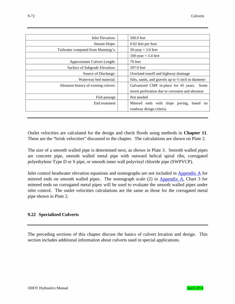
9-72 Culverts
Inlet Elevation: 500.0 feet
Stream Slope: 0.02 feet per foot Tailwater computed from Manning’s: 50-year = 3.0 feet
100-year = 3.4 feet Approximate Culvert Length: 70 feet
Surface of Subgrade Elevation: 507.0 feet Source of Discharge: Overland runoff and highway drainage
Waterway bed material: Silts, sands, and gravels up to ½ inch in diameter Abrasion history of existing culvert: Galvanized CMP in-place for 45 years. Some
invert perforation due to corrosion and abrasion Fish passage Not needed
End treatment Mitered ends with slope paving, based on roadway design criteria
Outlet velocities are calculated for the design and check floods using methods in Chapter 11. These are the “brink velocities” discussed in the chapter. The calculations are shown on Plate 2. The size of a smooth walled pipe is determined next, as shown in Plate 3. Smooth walled pipes are concrete pipe, smooth walled metal pipe with outward helical spiral ribs, corrugated polyethylene Type D or S pipe, or smooth inner wall polyvinyl chloride pipe (SWPVCP). Inlet control headwater elevation equations and nomographs are not included in Appendix A for mitered ends on smooth walled pipes. The nomograph scale (2) in Appendix A, Chart 3 for mitered ends on corrugated metal pipes will be used to evaluate the smooth walled pipes under inlet control. The outlet velocities calculations are the same as those for the corrugated metal pipe shown in Plate 2.
9.22 Specialized Culverts
The preceding sections of this chapter discuss the basics of culvert location and design. This section includes additional information about culverts used in special applications.
ODOT Hydraulics Manual April 2014
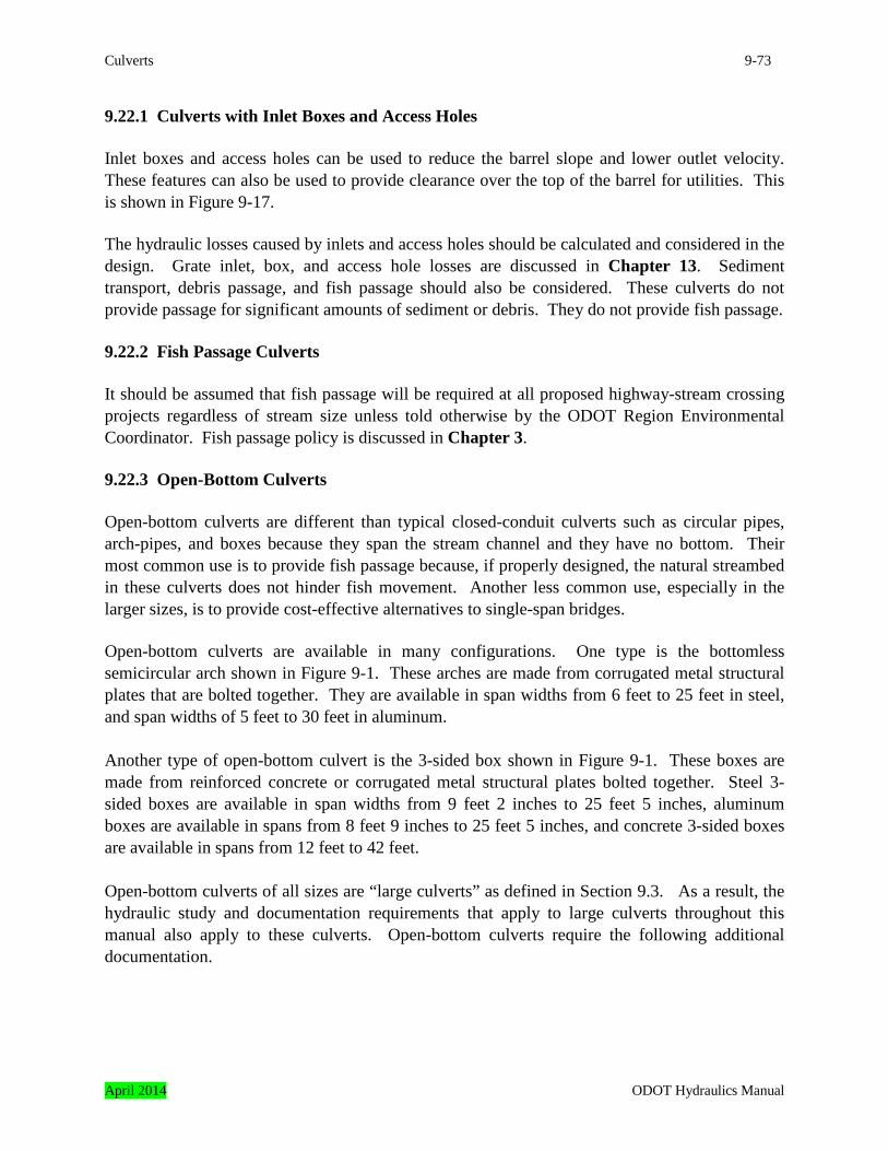
Culverts 9-73
9.22.1 Culverts with Inlet Boxes and Access Holes Inlet boxes and access holes can be used to reduce the barrel slope and lower outlet velocity. These features can also be used to provide clearance over the top of the barrel for utilities. This is shown in Figure 9-17. The hydraulic losses caused by inlets and access holes should be calculated and considered in the design. Grate inlet, box, and access hole losses are discussed in Chapter 13. Sediment transport, debris passage, and fish passage should also be considered. These culverts do not provide passage for significant amounts of sediment or debris. They do not provide fish passage. 9.22.2 Fish Passage Culverts It should be assumed that fish passage will be required at all proposed highway-stream crossing projects regardless of stream size unless told otherwise by the ODOT Region Environmental Coordinator. Fish passage policy is discussed in Chapter 3. 9.22.3 Open-Bottom Culverts Open-bottom culverts are different than typical closed-conduit culverts such as circular pipes, arch-pipes, and boxes because they span the stream channel and they have no bottom. Their most common use is to provide fish passage because, if properly designed, the natural streambed in these culverts does not hinder fish movement. Another less common use, especially in the larger sizes, is to provide cost-effective alternatives to single-span bridges. Open-bottom culverts are available in many configurations. One type is the bottomless semicircular arch shown in Figure 9-1. These arches are made from corrugated metal structural plates that are bolted together. They are available in span widths from 6 feet to 25 feet in steel, and span widths of 5 feet to 30 feet in aluminum. Another type of open-bottom culvert is the 3-sided box shown in Figure 9-1. These boxes are made from reinforced concrete or corrugated metal structural plates bolted together. Steel 3-sided boxes are available in span widths from 9 feet 2 inches to 25 feet 5 inches, aluminum boxes are available in spans from 8 feet 9 inches to 25 feet 5 inches, and concrete 3-sided boxes are available in spans from 12 feet to 42 feet. Open-bottom culverts of all sizes are “large culverts” as defined in Section 9.3. As a result, the hydraulic study and documentation requirements that apply to large culverts throughout this manual also apply to these culverts. Open-bottom culverts require the following additional documentation.
April 2014 ODOT Hydraulics Manual
9-74 Culverts
9.22.3.1 Hydraulic Study and Documentation
1. Crown and channel elevations at the culvert ends. These elevations are listed in lieu of the invert elevations in the description of a closed-conduit culvert. The crown is the highest point on the inside of the culvert, as shown in Figure 9-18.
2. Hydraulic data tables for each suitable shape. The hydraulic characteristics of open-
bottom culverts of similar rise and span can vary considerably depending on the waterway shape.
3. A description of predicted scour types including elevations. If the channel is expected to
degrade or aggrade during the design life of the structure, this should be noted. The expected change in the channel elevation should be listed.
4. If the channel is expected to degrade, the foundation recommendations should take this
into consideration. If the channel is expected to aggrade, the crown elevations or the culvert size should consider this. These aspects of the design should be documented.
5. A description of the footing protection. If riprap is used, the class of riprap should be
noted, whether or not it is to be grouted, and whether or not a filter blanket is needed under the riprap. A detail showing the approximate dimensions of the footing protection should be included. Typically, the footing elevations are not listed or shown. Usually these elevations are determined during the structural and/or foundation design.
9.22.3.2 Minimum Culvert Size An open-bottomed culvert spans a section of the natural stream channel that is typically composed of loose material such as sands, gravels, etc. Some or all of this material may be scoured away and replaced during large floods. Typically, the loss of bed material occurs during the beginning (rising limb) of the flood and it is replaced as the flood recedes (falling limb).
ODOT Hydraulics Manual April 2014
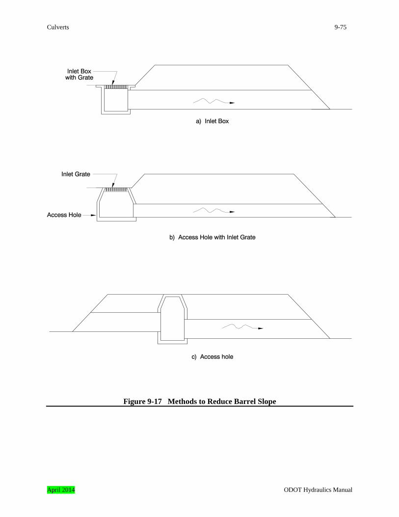
Culverts 9-75
Figure 9-17 Methods to Reduce Barrel Slope
April 2014 ODOT Hydraulics Manual
9-76 Culverts
The stream may deposit the bed material upstream from the inlet rather than inside the barrel if the culvert is too small to span the active stream channel. In addition, excessive scour may occur inside the barrel. As a result, care must be taken to assure that the culvert meets or exceeds the minimum culvert size requirements listed in Section 9.12. It is important that maintenance forces have access to the inside of the culvert for inspection or repair. In addition, revetment may be needed to protect the footings in some instances, and it needs to be inspected and replaced if it is scoured away. Clearance requirements should be requested from maintenance personnel on a project by project basis. Typical clearance requirements are an 8-foot by 8-foot minimum opening width to facilitate small equipment if a scour situation develops. 9.22.3.3 End Treatment There are many open-bottom culverts on the state highway system. Sloped ends with reinforced concrete collars or slope paving are the most common end treatment for metal open-bottom arches. Headwalls and wingwalls are also used. Headwalls with wingwalls are the most common end treatment for the reinforced concrete arches. The end treatment requirements listed in Section 9.14 also apply to open-bottom culverts. In addition, skew cut sloped ends are not permitted on corrugated metal open-bottom arches unless the end is reinforced by a concrete collar, slope paving, or similar treatment. If an arch with unskewed ends is placed on a skew, the roadway embankment should be contour graded to match the ends as shown on Standard Drawing RD320. 9.22.3.4 Hydraulic Modeling The inlet and outlet control equations and nomographs described in Section 9.18 can be used to analyze open-bottom culverts if a scour analysis is not needed. This would apply to culverts whose footings are solidly keyed into non-erodible material and permanently protected from the scour associated with turbulent flow, high velocity flow, or pressure flow if they occur. Inlet and outlet control nomographs for many arch shapes are included in Appendix A, and hydraulic properties are listed in Chapter 8 Appendix B. Hydraulic data for open-bottom culverts with other shapes are listed in manufacturer’s trade literature. A step-backwater analysis is needed if scour elevations must be considered. This applies to culverts whose footings are fully or partially founded on erodible material or soils and rock with an unknown erosion resistance.
ODOT Hydraulics Manual April 2014
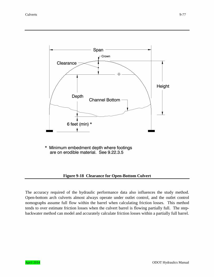
Culverts 9-77
Figure 9-18 Clearance for Open-Bottom Culvert The accuracy required of the hydraulic performance data also influences the study method. Open-bottom arch culverts almost always operate under outlet control, and the outlet control nomographs assume full flow within the barrel when calculating friction losses. This method tends to over estimate friction losses when the culvert barrel is flowing partially full. The step-backwater method can model and accurately calculate friction losses within a partially full barrel.
April 2014 ODOT Hydraulics Manual
9-78 Culverts
9.22.3.5 Scour In general, open-bottom culverts with footings solidly keyed into non-erodible rock can withstand a temporary loss of streambed material due to scour during large floods. Open-bottom culverts with this type of foundation are preferred. Occasionally open-bottom arch culverts are installed with footings on erodible material. This is done over canals, irrigation ditches, and other sites where all of these conditions can be met:
• the flows are regulated, or if not regulated, they can be predicted with certainty, • the channel is stable in both vertical and horizontal alignment, • debris passage is not a concern, • there will be no hydraulic drops or jumps within the barrel or near the ends, • clearance can be provided between the culvert crown and the water surface during the
maximum predicted discharge, as shown in Figure 9-18, • flow contraction into the culvert barrel is minimal and contraction scour is not a concern,
and • the footing bottoms are located at least six feet below the channel bottom, as shown in
Figure 9-18. Methods to predict scour in open-bottom culverts are being developed by the FHWA. Research indicates the deepest scour in open-bottom culverts occurs at the corners of the culvert inlet where the flow contracts as it enters the culvert barrel. Reports are available on the FHWA website: http://www.fhwa.dot.gov/engineering/hydraulics/scourtech/index.cfm. The conclusions and recommendations from these studies should be considered when estimating scour. 9.22.3.6 Footing Protection Typically, the foundation of an open-bottom culvert will be one of these three types.
1. The footings for an existing culvert, the footings for an extension to an existing culvert, or the footings for a culvert proposed at a new location; are, or can be, keyed into solid non-erodible rock. Revetment is not needed to protect the footings in these cases.
2. The footings of an existing culvert are keyed into rock with questionable erosion
resistance, or, it is not known with absolute certainty that the footings for a proposed extension or new culvert can be keyed into solid rock for their entire length. Cores, potholes, or other subsurface exploration indicates rock is present at footing depth. Revetment is needed in these cases to assure the footings are protected.
The footings are founded on erodible rock or loose material and the culvert meets the criteria listed in the previous subsection. In this case, the footings are protected by revetment.
ODOT Hydraulics Manual April 2014
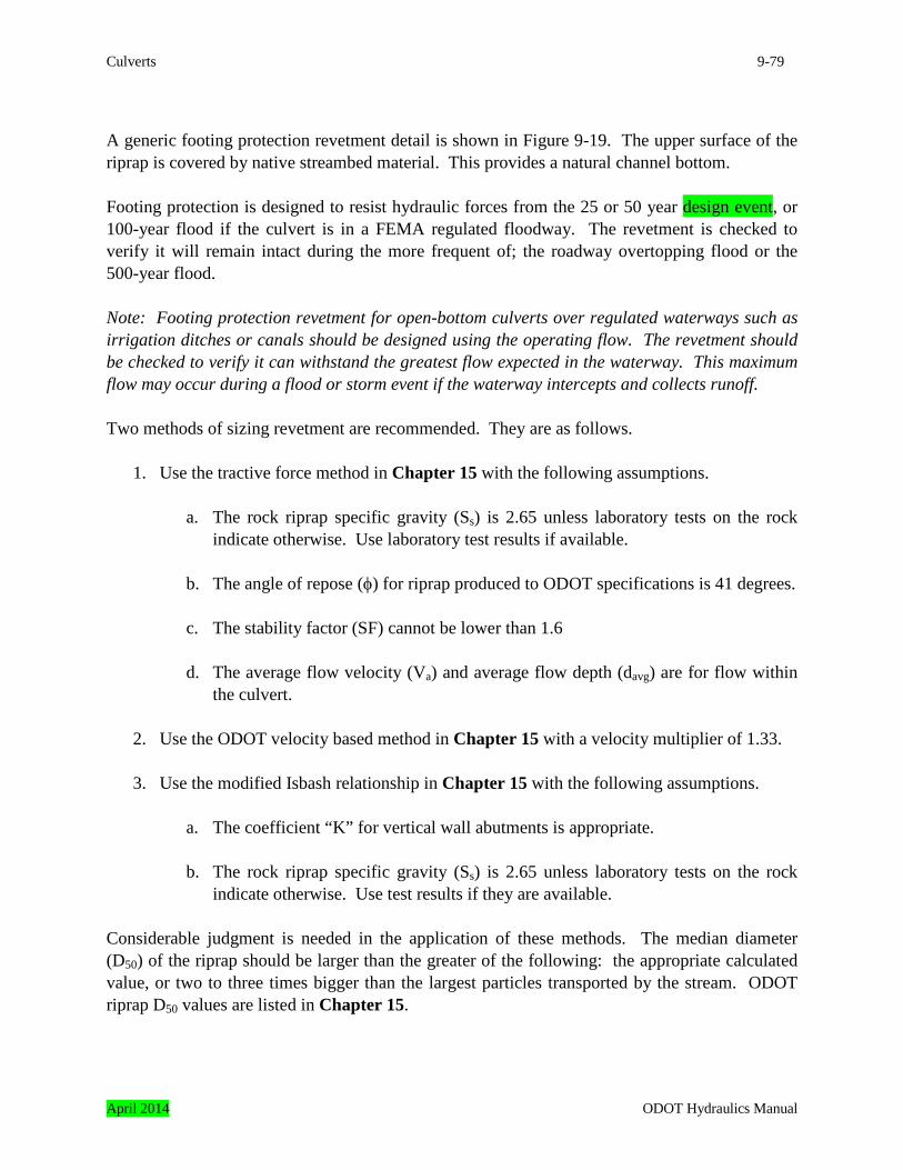
Culverts 9-79
A generic footing protection revetment detail is shown in Figure 9-19. The upper surface of the riprap is covered by native streambed material. This provides a natural channel bottom. Footing protection is designed to resist hydraulic forces from the 25 or 50 year design event, or 100-year flood if the culvert is in a FEMA regulated floodway. The revetment is checked to verify it will remain intact during the more frequent of; the roadway overtopping flood or the 500-year flood. Note: Footing protection revetment for open-bottom culverts over regulated waterways such as irrigation ditches or canals should be designed using the operating flow. The revetment should be checked to verify it can withstand the greatest flow expected in the waterway. This maximum flow may occur during a flood or storm event if the waterway intercepts and collects runoff. Two methods of sizing revetment are recommended. They are as follows.
1. Use the tractive force method in Chapter 15 with the following assumptions.
a. The rock riprap specific gravity (Ss) is 2.65 unless laboratory tests on the rock indicate otherwise. Use laboratory test results if available.
b. The angle of repose (φ) for riprap produced to ODOT specifications is 41 degrees.
c. The stability factor (SF) cannot be lower than 1.6
d. The average flow velocity (Va) and average flow depth (davg) are for flow within
the culvert. 2. Use the ODOT velocity based method in Chapter 15 with a velocity multiplier of 1.33.
3. Use the modified Isbash relationship in Chapter 15 with the following assumptions.
a. The coefficient “K” for vertical wall abutments is appropriate.
b. The rock riprap specific gravity (Ss) is 2.65 unless laboratory tests on the rock indicate otherwise. Use test results if they are available.
Considerable judgment is needed in the application of these methods. The median diameter (D50) of the riprap should be larger than the greater of the following: the appropriate calculated value, or two to three times bigger than the largest particles transported by the stream. ODOT riprap D50 values are listed in Chapter 15.
April 2014 ODOT Hydraulics Manual
9-80 Culverts
Figure 9-19 Typical Footing Protection Detail 9.22.4 Sag (Inverted Siphon) Culverts A sag culvert, sometimes called an inverted siphon, is a culvert with multiple sections, as shown in Figure 9-20. The end section inverts are at the elevations of the stream flowlines, and the central section is lower than the end sections. These culverts are used to convey flow under an obstruction such as a highway, railroad, or utility. These culverts are commonly used for conveying irrigation water under highways. In these instances, the elevation changes at each end of the culvert occur in reinforced concrete boxes called “siphon boxes” where the end pipes enter the box at higher elevations than the center pipe. These culverts can provide fish passage. These culverts can collect sediment because they are the lowest points in the stream channel. A sediment trap may be needed upstream from the culvert if the waterway conveys sediment. There should be provisions for cleaning the culvert such as manholes to allow access to the depressed central section if a sediment trap cannot be provided. The culvert can be cleaned during the non-irrigation season if it is on a canal. Standing water may need to be pumped out to clean the culvert.
ODOT Hydraulics Manual April 2014
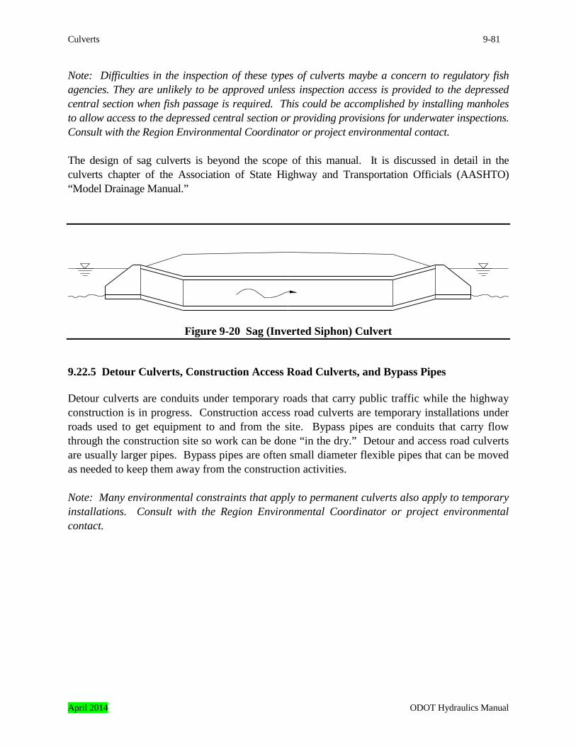
Culverts 9-81
Note: Difficulties in the inspection of these types of culverts maybe a concern to regulatory fish agencies. They are unlikely to be approved unless inspection access is provided to the depressed central section when fish passage is required. This could be accomplished by installing manholes to allow access to the depressed central section or providing provisions for underwater inspections. Consult with the Region Environmental Coordinator or project environmental contact. The design of sag culverts is beyond the scope of this manual. It is discussed in detail in the culverts chapter of the Association of State Highway and Transportation Officials (AASHTO) “Model Drainage Manual.”
Figure 9-20 Sag (Inverted Siphon) Culvert 9.22.5 Detour Culverts, Construction Access Road Culverts, and Bypass Pipes Detour culverts are conduits under temporary roads that carry public traffic while the highway construction is in progress. Construction access road culverts are temporary installations under roads used to get equipment to and from the site. Bypass pipes are conduits that carry flow through the construction site so work can be done “in the dry.” Detour and access road culverts are usually larger pipes. Bypass pipes are often small diameter flexible pipes that can be moved as needed to keep them away from the construction activities. Note: Many environmental constraints that apply to permanent culverts also apply to temporary installations. Consult with the Region Environmental Coordinator or project environmental contact.
April 2014 ODOT Hydraulics Manual
9-82 Culverts
The minimum end areas of detour and access road culverts are calculated by the agency and included in plans or specifications along with the period of the year when they can be used and any other requirements. Examples of typical recommendations are: “Detour or access road culverts in place throughout the entire year should have inverts buried in the stream bottom at least one-third the culvert diameter or rise. The minimum net end area, after subtracting the area filled with streambed material, is ____ square feet.”
or “The minimum end area for a detour or access road culvert in place from the ___ of___ through the ___ of___ is ___ square feet.” During project development the hydraulics designer has little to no information about the detour or road access pipes. These are placed during construction by the contractor. The hydraulics designer uses “worst case” assumptions to estimate the pipe end area, as follows:
• the maximum headwater depth to diameter ratio (HW/D) is less than or equal to one, • the tailwater depth is less than critical depth, • the inlet will be a projecting end, • the barrel will be corrugated metal, and • the pipe slope will be nearly flat.
Temporary Water Management bypass pipes sizes are estimated by the hydraulics designer to develop the TWM plan and cost estimates. Guidance for the design of Temporary Water Management facilities are discusses in Chapter 18. The preceding worst case assumptions are often used. The pipe end areas are not listed on the contract documents. Instead, a table of estimated daily exceedance discharges is provided. Guidelines for exceedance discharge recurrence intervals are in Chapter 3 and hydrology methods are discussed in Chapter 7.
9.23 Extending Existing Culverts Often an existing culvert needs to be extended. This occurs most frequently when a roadway is to be widened. It should be verified that the extended culvert will provide adequate hydraulic performance, fish passage, and adequate service life when an extension is considered. Culvert extensions are subject to several requirements based on pipe materials, as described in Chapter 5. The hydraulic performance of both the existing and extended culvert must be analyzed and compared. Often an inlet with increased hydraulic efficiency can be used to compensate for the increased friction losses caused by the longer barrel, and headwater elevations will not be increased by the extension.
ODOT Hydraulics Manual April 2014
Culverts 9-83
An existing culvert meeting fish passage requirements can often be extended if the modified culvert also will meet passage requirements. Extension of a culvert, where the existing culvert must be modified to pass fish, is often considered to be a “retrofit.” These are not always allowed by the regulatory agencies. Any culvert extension involving fish passage where the existing section must be modified to provide fish passage should be carefully reviewed with the project environmental contact in the early stages of the project, and prior to detailed design. The existing culvert to be extended must have sufficient remaining service life to last for the design life of the proposed project. Often this will require a culvert replacement rather than extension, or the existing pipe will need to be rehabilitated. Trenchless methods are often used for pipe rehabilitation, as discussed in Chapter 16. 9.24 Scour at Culvert Outlets Flow out of culverts is typically fast and shallow in comparison to flow in the downstream channel. In addition, there is often turbulence caused by hydraulic jumps or drops where culvert flow makes a transition to channel flow. These flow transitions can create scour holes in the channel bottom downstream from the outlet. This outlet scour should be considered in culvert design as follows. 1. Place riprap or construct an energy dissipator at the culvert outlet to prevent or minimize
scour on ODOT right-of-way or adjacent property. This is the most common solution to outlet scour problems. Outlet scour protection is especially critical for relief culverts and other culverts placed in embankments at elevations higher than the stream flowline.
2. Do not provide scour protection. This can be done if the outlet channel is non-erodible or a
scour hole can be tolerated. The scour hole must:
• not undermine the culvert, embankment, structures, or cause unacceptable damage, • be confined to the ODOT right-of-way, or extend off of the right-of-way if suitable
easements are obtained from adjacent landowners, • not cause intolerable environmental damage, and • not obstruct fish passage if fish passage is needed.
The need for energy dissipators should be determined early in the design process. These facilities can significantly increase the cost of the culvert and often require additional right-of-way. Methods to estimate scour hole size, and procedures to design energy dissipators such as riprap blankets, riprap lined basins, or pipe tee outlet dissipators are presented in Chapter 11. Dissipators such as stilling wells, roughness rings inside the culvert barrel, or impact basins are discussed in the FHWA’s Hydraulic Engineering Circular No. 14 (HEC-14), “Hydraulic Design
April 2014 ODOT Hydraulics Manual

9-84 Culverts
of Energy Dissipators for Culverts and Channels.” Scour hole size estimates and the dissipators described in HEC-14. 9.25 Embankment Scour near Culverts Flow into and out of culverts is often turbulent, especially during large floods. This flow can damage the highway embankments around the culvert ends. The locations where this damage is expected are “scour critical areas” and they are protected by revetment and/or a suitable biotechnical method. The most common scour protection material is loose riprap, and other types are occasionally used, such as gabions or masonry walls. Vegetal bank protection generally is not adequate unless it is founded on a non-erodible underlayer such as riprap, a cable-reinforced articulating block mat, or an equivalent. Vegetation such as bushes are sometimes planted in riprap. Often the riprap is covered by soil before planting. Typically small willows are used and they are planted as close as 2 feet on centers in areas where their roots will be moist or wet during low flow periods. Large plants are not allowed within specified distances of the highway or near the culvert structure. The hydraulics designer should be contacted for guidance if plantings in riprap are considered. A description of scour protection for critical areas is included in the Hydraulic Report. Typical embankment protection is shown in Figure 9-21. This protection should extend up the embankment to the lower of:
• the elevation shown in Figure 9-21, or • the elevation of the bottom of the aggregate base.
ODOT Hydraulics Manual April 2014
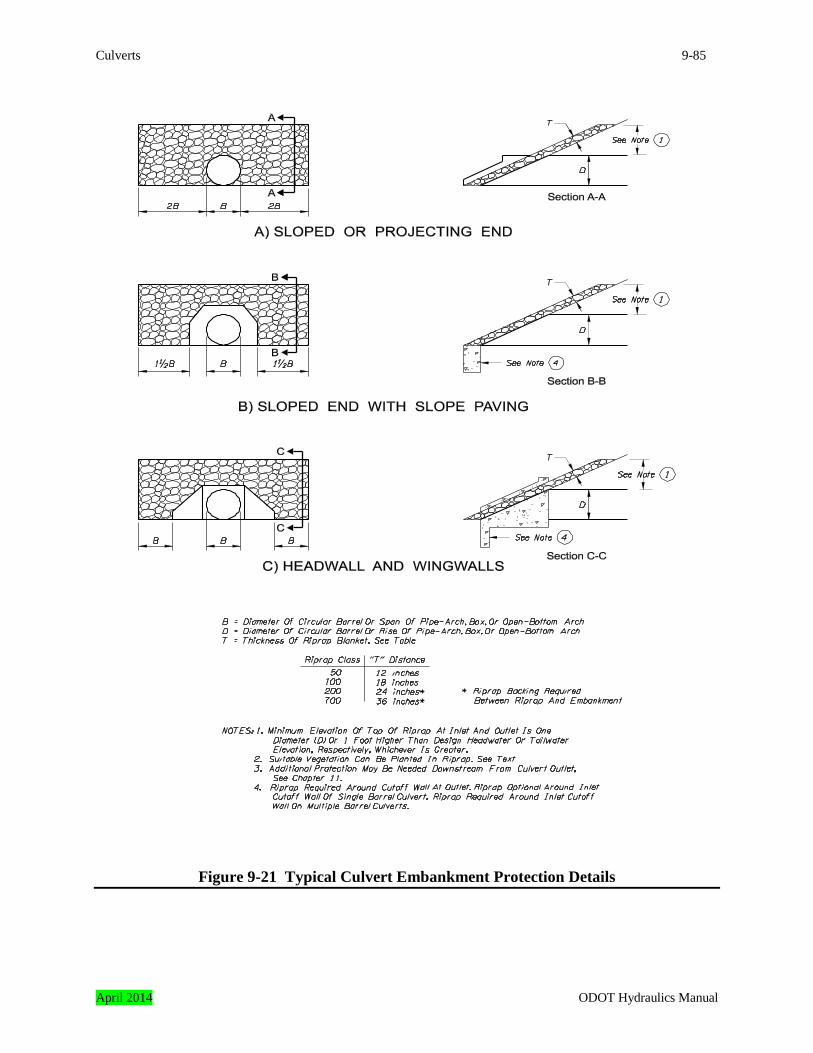
Culverts 9-85
Figure 9-21 Typical Culvert Embankment Protection Details
April 2014 ODOT Hydraulics Manual

9-86 Culverts
In general, Class 50 loose riprap is suitable for small and medium culverts, and Class 100 for large culverts. Larger rock is sometimes used when the energy dissipator requires larger riprap, and there may be a cost savings by using larger rock for both the embankment and the dissipator. In other cases, the larger rock may be needed to resist scour. An example is a culvert outlet on a lakeshore. Larger riprap may be needed to resist displacement from the waves on the lake. Cutoff walls are often used at culvert ends to prevent undermining due to scour. Riprap is placed against the outlet wall. Revetment is also placed against the inlet cutoff wall of multiple barrel or multiple culverts. Riprap is optional around the inlet cutoff wall of single barrel installations. Cutoff wall protection details are provided in Chapter 11. Note: The typical details described in this subsection are applicable for most installations. Some culverts may require additional protection. It is the responsibility of the designer to evaluate the need for additional protection and to include it in the design.
9.26 Debris Control
The potential for debris should be considered in the design. Accumulation of debris at the culvert inlet can result in the culvert not performing as designed and cause damage to the highway, culvert, and upstream property. The presence and extent of an existing debris passage problem can be determined by contacting maintenance personnel and neighboring landowners, examining the site, watershed, and nearby structures, and by reviewing maintenance records. Refer to Appendix C of this chapter for design guidelines when a debris control structure is necessary. There are several options for coping with debris. Selection of an option should consider:
• the extent of damage that would occur if the culvert plugs in comparison to the cost of a structure which will pass the debris,
• ease of removing debris from the culvert, • fish passage, if required, and • preferences of maintenance personnel.
Options for coping with a debris problem are: 1. Retain the debris upstream of the culvert by installing a trash rack. Use of a trash rack is
subject to approval by regulatory agencies reviewing the fish passage design if passage is required.
ODOT Hydraulics Manual April 2014
Culverts 9-87
2. Do not put a trash rack on the main culvert and construct an overflow culvert higher on the embankment to handle flow if the main culvert plugs. A trash rack may be needed upstream from the overflow culvert.
3. Select a structure large enough to pass the debris. In some instances this may require a
bridge rather than a culvert.
9.27 Piping Piping is caused by seepage along a culvert barrel which removes fill material, forming a void similar to a pipe, hence the term piping. Fine soil particles are washed out freely along the void and can ultimately cause embankment failure. The water causing seepage typically enters the embankment fill from two locations. One location is an open pipe joint or a hole in the barrel.. The other location is the interface between the barrel and the embankment at the culvert inlet. Precautions against piping include:
• using watertight joints (especially important if culvert operates under pressure flow), • constructing a headwall or slope paving with a minimum 3-foot deep cutoff wall at the inlet
and outlet, or • placing the culvert in an impermeable bedding.
Note: It is important that cutoff walls are constructed according to plans. Observations of past projects indicate these walls are often not constructed to the specified depths. Cut-off walls are one of the best features to prevent piping.
9.28 Flotation Flotation is the failure of a culvert that is caused by buoyancy. Buoyancy is an uplifting force that is produced when the pressure outside the culvert is greater than the pressure inside the barrel. The resulting uplift may cause the culvert or the inlet end of the culvert to rise out of the embankment. Typically, when flotation occurs the inlet is submerged and the culvert is flowing partially full under inlet control. The causes of inlet control can be an inefficient inlet, debris blocking the inlet, or damage to the inlet.
April 2014 ODOT Hydraulics Manual
9-88 Culverts
Some types of culverts are more susceptible to flotation than others. Vulnerable culverts are usually:
• relatively large pipes with little depth of cover from the roadway embankment, • thin walled, light, and flexible barrels such as corrugated metal or plastic, • barrels with projecting ends or mitered ends without collars or slope paving (ends projecting
unduly far out of the fill are especially vulnerable), or • use a mitered end surrounded by large riprap or boulders.
Detour culverts or culverts under construction are typically the most susceptible to flotation because they usually have projecting ends and little cover. Especially vulnerable are culverts operating under inlet control which, due to stage construction or other reasons, project far upstream from the fill. Countermeasures to prevent flotation include:
• use slope paving, concrete collars, or headwalls and wingwalls to weight down and protect the ends of metal pipes,
• consider the possibility that high flows may occur during construction and assure that uncovered pipes do not project far upstream from the fill,
• use multiple culverts rather than a large single barrel to increase fill cover heights, or • use heavy rigid barrels such as concrete pipe sections linked with tie bars.
9.29 Camber
Culverts installed under moderate to high fills can experience differential settlement. This occurs after the fill settles and compacts and the midsection of the culvert drops to a lower elevation than the outlet. To prevent this from occurring, the culvert is placed with a slightly elevated midsection and the pipe straightens when the fill settles. The increase in midsection elevation is called camber, and it is predicted by the Foundations Engineer. A profile showing the pipe camber needs to be included in the plans.
9.30 Flap Gates A flap gate, often called tide gate, is sometimes used on the end of a culvert to limit backflow through the conduit. The most common use of a flap gate is to prevent the inundation of upland property on one side of the highway from a high tide or flood on the other side of the highway. Although a flap gate may be useful in certain circumstances, some factors to be considered before it is specified are listed below.
1. Hydraulic efficiency. The effect of a flap gate on the hydraulic efficiency of the culvert
ODOT Hydraulics Manual April 2014
Culverts 9-89
should be considered in the design. Typically the effects are analyzed as “other losses,” as discussed in Subsection 9.19.2.
2. Fish passage. Fish passage requirements can preclude the use of a flap gate or require use of
a "fish friendly" gate. The ODOT Region Environmental Coordinator or appropriate regulatory agencies should be contacted before use of a tide gate is considered on a fish bearing stream.
3. Environmental concerns. Installation of a flap gate in a coastal location may alter the
circulation patterns of fresh, brackish, and salt water. These changes may affect the plants and wildlife in the vicinity. As a result, a flap gate should not be installed unless potential environmental effects are considered. It may not always prevent flooding upstream of the gate. If the gate stays closed too long and there is considerable runoff upstream, the gate could make the upstream flooding worse or provide no flood protection.
4. Flood control concerns. A flap gate should not be used to control flooding unless the effects
on all affected landowners are considered. A gate may relieve flooding at one location and make it worse at another.
5. Maintenance. A flap gate may be held open by debris, it can be damaged, and is subject to
wear. Periodic inspection and/or maintenance may be needed. 6. Embankment stability. The flow restriction caused by a flap gate may result in a difference
in water surface elevations on either side of the highway. The ability of the roadway embankment to withstand the resulting hydrostatic pressure should be considered before a gate is specified.
ODOT policy addressing tidegates is posted on the ODOT Business Services website. The designer should review this policy and assure the proposed design is in conformance.
April 2014 ODOT Hydraulics Manual
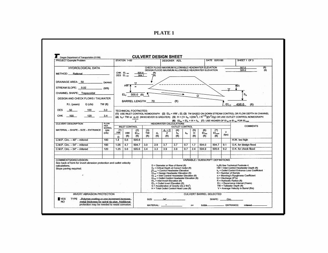
PLATE 1
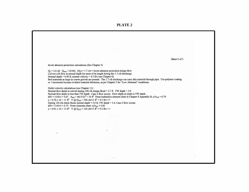
PLATE 2
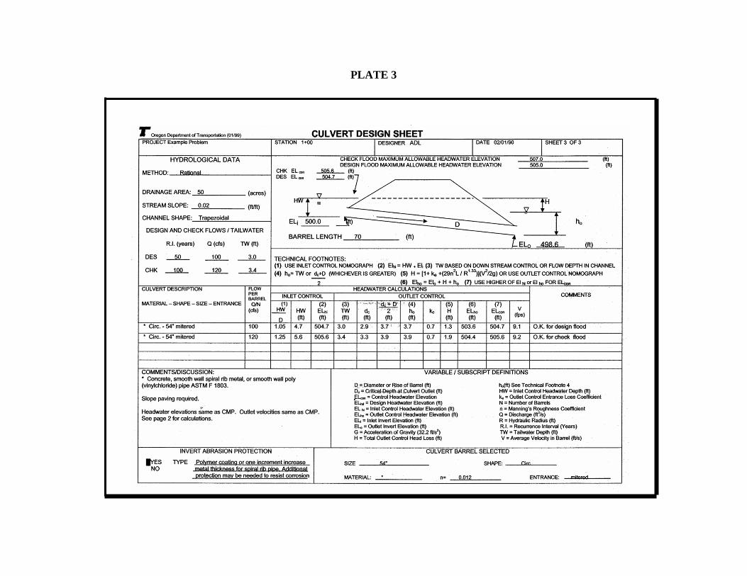
PLATE 3