Embed Size (px)
Citation preview

CHAPTER 9 “MEMBERS DESIGN”
2
CONTENTS
I. DETAILED DESCRIPTION OF THE NEW INTERFACE 4
1. Members Design 4
1.1. Scenarios 4
1.2. Beams 35
1.3. Capacity design 42
1.4. Columns 44
1.5. Footing 50
1.6. Slabs-Mesh 53

CHAPTER 9 “MEMBERS DESIGN”
3
I. THE NEW UPGRADED INTERFACE of SCADA Pro
CHAPTER 9 “MEMBERS DESIGN”
4
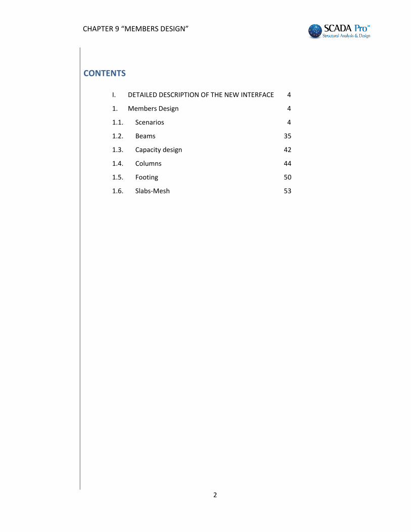
I. DETAILED DESCRIPTION OF THE NEW INTERFACE In the new upgraded SCADA Pro all program commands are grouped in 11 Units.
1. Members Design
The 9th Unit entitled "Members Design" contains the following 8 groups of commands:
1. Scenarios 2. Beams 3. Capacity Design 4. Columns 5. Footings 6. Slabs - Mesh 7. Steel 8. Timber 9. Masonry Design – 2D Diagrams
Since model analysis has been completed, the design checks of the structural elements are applied according to the design code provisions, defined in the tab “Member Design”. The reinforcement of the structural elements is calculated according to the design checks.
1.1. Scenarios
The “Scenarios” command group contains the commands for the creation of a new scenario as well as the editing of the parameters of the design checks and reinforcement in every type of structural elements.
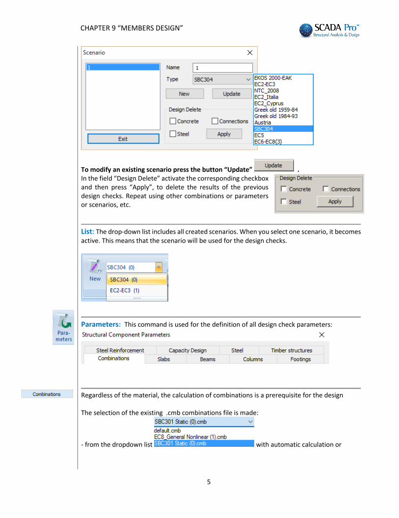
New: This command is used to create a new scenario. Type a name, select the corresponding
design regulation and then press the button . The selection of the design code corresponds to the design checks of the structural elements and the calculation of the steel reinforcement. For the SBC 304, you must create the SBC304 scenario for the design and the checks of the concrete structures.
CHAPTER 9 “MEMBERS DESIGN”
5
To modify an existing scenario press the button “Update” . In the field “Design Delete” activate the corresponding checkbox and then press “Apply”, to delete the results of the previous design checks. Repeat using other combinations or parameters or scenarios, etc.
List: The drop-down list includes all created scenarios. When you select one scenario, it becomes active. This means that the scenario will be used for the design checks.
Parameters: This command is used for the definition of all design check parameters:
Regardless of the material, the calculation of combinations is a prerequisite for the design The selection of the existing .cmb combinations file is made:
- from the dropdown list with automatic calculation or
CHAPTER 9 “MEMBERS DESIGN”
6
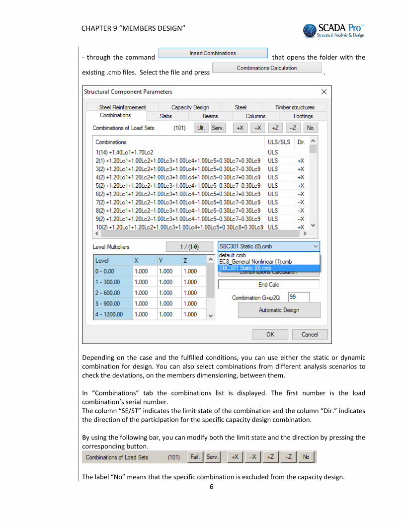
- through the command that opens the folder with the
existing .cmb files. Select the file and press .
Depending on the case and the fulfilled conditions, you can use either the static or dynamic combination for design. You can also select combinations from different analysis scenarios to check the deviations, on the members dimensioning, between them. In “Combinations” tab the combinations list is displayed. The first number is the load combination’s serial number. The column “SE/ST” indicates the limit state of the combination and the column “Dir.” indicates the direction of the participation for the specific capacity design combination. By using the following bar, you can modify both the limit state and the direction by pressing the corresponding button.
The label “No” means that the specific combination is excluded from the capacity design.
CHAPTER 9 “MEMBERS DESIGN”
7
SBC 304
SBC 301
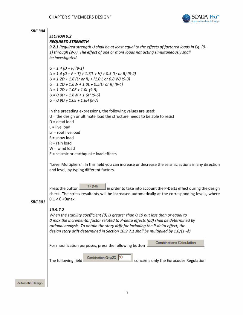
SECTION 9.2 REQUIRED STRENGTH 9.2.1 Required strength U shall be at least equal to the effects of factored loads in Eq. (9- 1) through (9-7). The effect of one or more loads not acting simultaneously shall be investigated. U = 1.4 (D + F) (9-1) U = 1.4 (D + F + T) + 1.7(L + H) + 0.5 (Lr or R) (9-2) U = 1.2D + 1.6 (Lr or R) + (1.0 L or 0.8 W) (9-3) U = 1.2D + 1.6W + 1.0L + 0.5(Lr or R) (9-4) U = 1.2D + 1.0E + 1.0L (9-5) U = 0.9D + 1.6W + 1.6H (9-6) U = 0.9D + 1.0E + 1.6H (9-7) In the preceding expressions, the following values are used: U = the design or ultimate load the structure needs to be able to resist D = dead load L = live load Lr = roof live load S = snow load R = rain load W = wind load E = seismic or earthquake load effects “Level Multipliers”: In this field you can increase or decrease the seismic actions in any direction and level, by typing different factors.
Press the button in order to take into account the P-Delta effect during the design check. The stress resultants will be increased automatically at the corresponding levels, where 0.1 < θ <θmax. 10.9.7.2 When the stability coefficient (θ) is greater than 0.10 but less than or equal to θ max the incremental factor related to P-delta effects (ad) shall be determined by rational analysis. To obtain the story drift for including the P-delta effect, the design story drift determined in Section 10.9.7.1 shall be multiplied by 1.0/(1 -θ).
For modification purposes, press the following button .
The following field concerns only the Eurocodes Regulation
CHAPTER 9 “MEMBERS DESIGN”
8
Automatic Design: This command offers the possibility for an automatic application of the appropriate design checks and the automatic designing of all structural elements, just by pressing the corresponding button. Set the parameters in the following tabs :
and then press the button
“Automatic Design” or follow step by step the procedure to design the structural elements with respect to the fulfillment of the design checks.
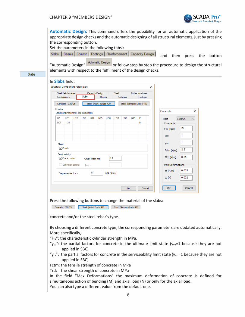
In Slabs field:
Press the following buttons to change the material of the slabs:
concrete and/or the steel rebar’s type. By choosing a different concrete type, the corresponding parameters are updated automatically. More specifically, “Fck”: the characteristic cylinder strength in MPa. “γcu”: the partial factors for concrete in the ultimate limit state (γcu=1 because they are not
applied in SBC) “γcs”: the partial factors for concrete in the serviceability limit state (γcs =1 because they are not
applied in SBC) Fctm: the tensile strength of concrete in MPa Trd: the shear strength of concrete in MPa In the field “Max Deformations” the maximum deformation of concrete is defined for simultaneous action of bending (M) and axial load (N) or only for the axial load. You can also type a different value from the default one.
CHAPTER 9 “MEMBERS DESIGN”
9
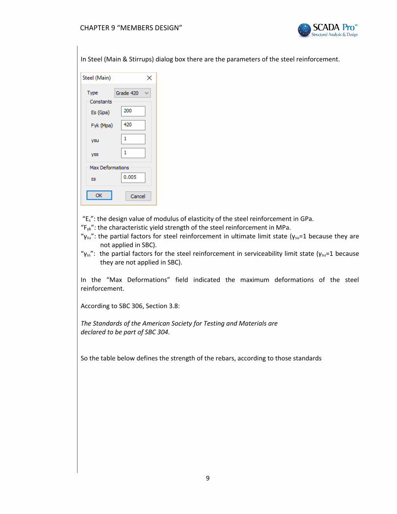
In Steel (Main & Stirrups) dialog box there are the parameters of the steel reinforcement.
“Es”: the design value of modulus of elasticity of the steel reinforcement in GPa. “Fyk”: the characteristic yield strength of the steel reinforcement in MPa. “γsu”: the partial factors for steel reinforcement in ultimate limit state (γsu=1 because they are
not applied in SBC). “γss”: the partial factors for the steel reinforcement in serviceability limit state (γsu=1 because
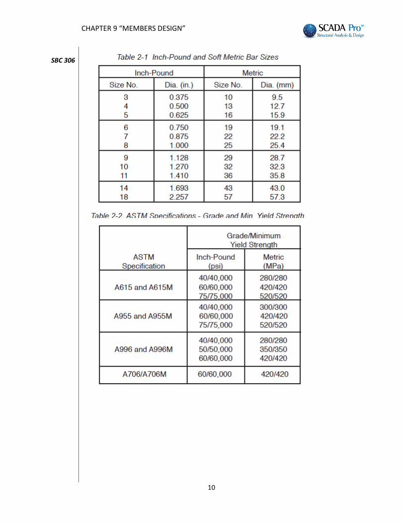
they are not applied in SBC). In the “Max Deformations” field indicated the maximum deformations of the steel reinforcement. According to SBC 306, Section 3.8: The Standards of the American Society for Testing and Materials are declared to be part of SBC 304. So the table below defines the strength of the rebars, according to those standards
CHAPTER 9 “MEMBERS DESIGN”
10
SBC 306
CHAPTER 9 “MEMBERS DESIGN”
11
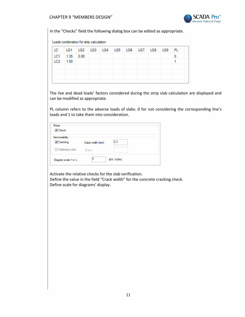
In the “Checks” field the following dialog box can be edited as appropriate.
The live and dead loads’ factors considered during the strip slab calculation are displayed and can be modified as appropriate. PL column refers to the adverse loads of slabs. 0 for not considering the corresponding line’s loads and 1 to take them into consideration.
Activate the relative checks for the slab verification. Define the value in the field “Crack width” for the concrete cracking check. Define scale for diagrams’ display.
CHAPTER 9 “MEMBERS DESIGN”
12
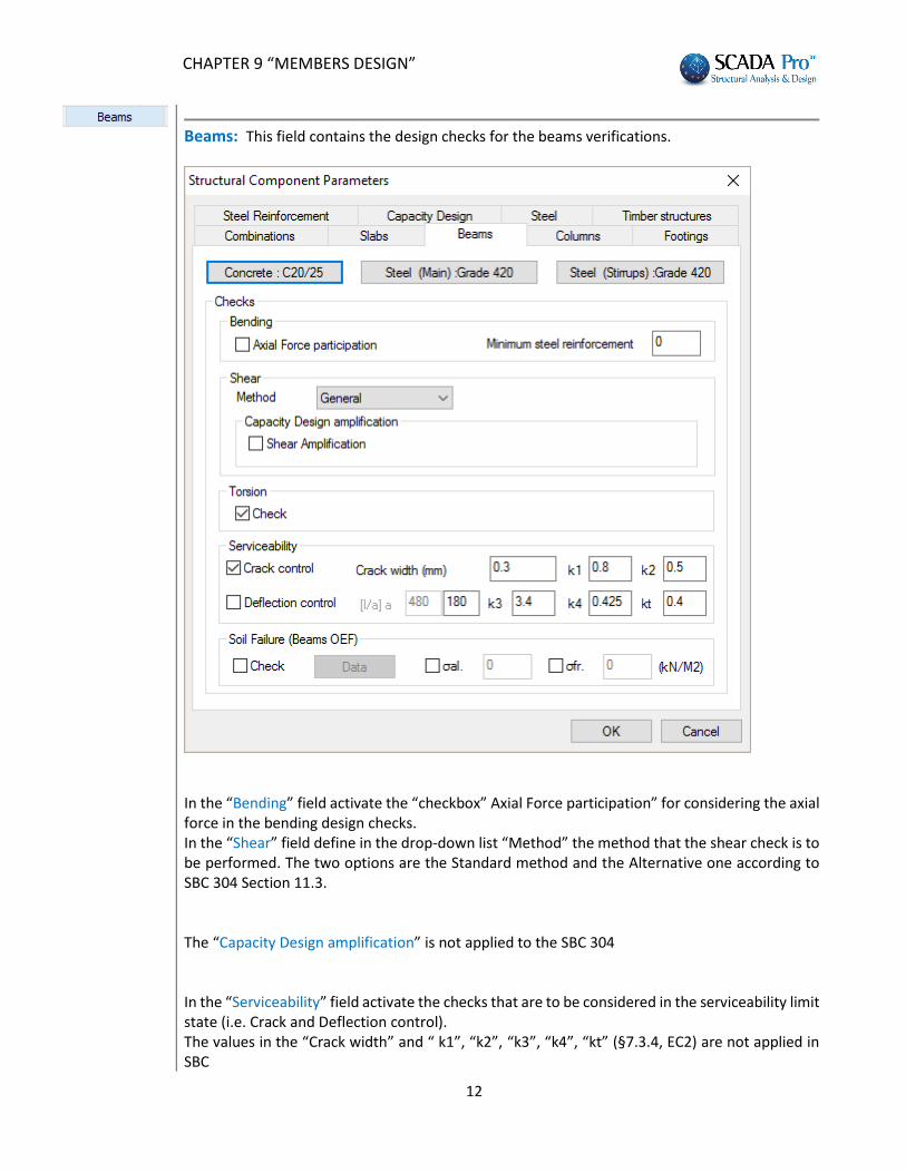
Beams: This field contains the design checks for the beams verifications.
In the “Bending” field activate the “checkbox” Axial Force participation” for considering the axial force in the bending design checks. In the “Shear” field define in the drop-down list “Method” the method that the shear check is to be performed. The two options are the Standard method and the Alternative one according to SBC 304 Section 11.3. The “Capacity Design amplification” is not applied to the SBC 304 In the “Serviceability” field activate the checks that are to be considered in the serviceability limit state (i.e. Crack and Deflection control). The values in the “Crack width” and “ k1”, “k2”, “k3”, “k4”, “kt” (§7.3.4, EC2) are not applied in SBC
CHAPTER 9 “MEMBERS DESIGN”
13
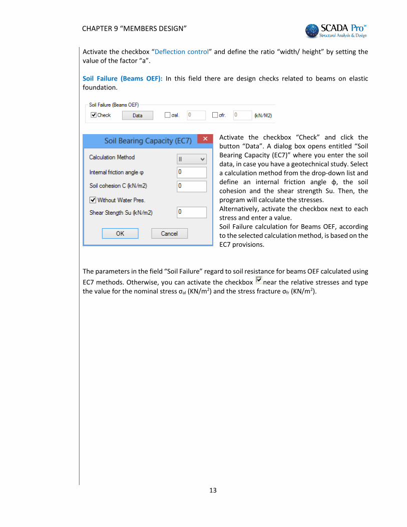
Activate the checkbox “Deflection control” and define the ratio “width/ height” by setting the value of the factor “a”. Soil Failure (Beams OEF): In this field there are design checks related to beams on elastic foundation.
Activate the checkbox “Check” and click the button “Data”. A dialog box opens entitled “Soil Bearing Capacity (EC7)” where you enter the soil data, in case you have a geotechnical study. Select a calculation method from the drop-down list and define an internal friction angle φ, the soil cohesion and the shear strength Su. Then, the program will calculate the stresses. Alternatively, activate the checkbox next to each stress and enter a value. Soil Failure calculation for Beams OEF, according to the selected calculation method, is based on the EC7 provisions.
The parameters in the field “Soil Failure” regard to soil resistance for beams OEF calculated using
ΕC7 methods. Otherwise, you can activate the checkbox near the relative stresses and type the value for the nominal stress σal (ΚΝ/m2) and the stress fracture σfr (ΚΝ/m2).
CHAPTER 9 “MEMBERS DESIGN”
14
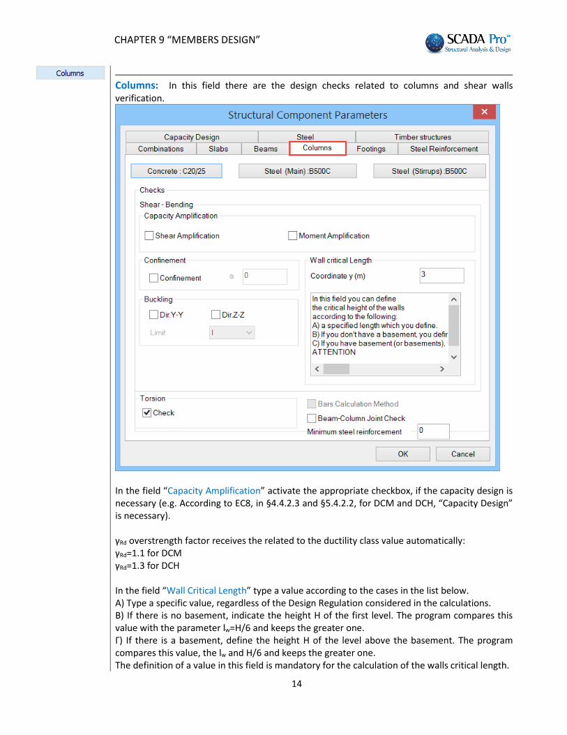
Columns: In this field there are the design checks related to columns and shear walls verification.
In the field “Capacity Amplification” activate the appropriate checkbox, if the capacity design is necessary (e.g. According to EC8, in §4.4.2.3 and §5.4.2.2, for DCM and DCH, “Capacity Design” is necessary). γRd overstrength factor receives the related to the ductility class value automatically: γRd=1.1 for DCM γRd=1.3 for DCH In the field “Wall Critical Length” type a value according to the cases in the list below. Α) Type a specific value, regardless of the Design Regulation considered in the calculations. Β) If there is no basement, indicate the height H of the first level. The program compares this value with the parameter lw=H/6 and keeps the greater one. Γ) If there is a basement, define the height H of the level above the basement. The program compares this value, the lw and H/6 and keeps the greater one. The definition of a value in this field is mandatory for the calculation of the walls critical length.
CHAPTER 9 “MEMBERS DESIGN”
15
§ 5.4.3.2.2, EC8
Activate the checkbox “Confinement” and type a value in the “a” field. Otherwise keep the checkbox inactive and the program will calculate the stirrups section and the distribution according to the paragraphs §5.4.3.2.2 and §5.4.3.4.2 of EC8*1. *1 For Columns (§ 5.4.3.2.2, EC8)
035.030o
c
d sy,dwd b
bv
(5.15)
Where
wd is the mechanical volumetric ratio of confining hoops within the critical regions;
cd
yd
f
f
coreconcreteofvolume
hoopsconfiningofvolumewd
is the required value of the curvature ductility factor;
d is the normalized design axial force (d = NEd / Acfcd);
sy,d is the design value of tension steel strain at yield For Walls (§ 5.4.3.4.2, EC8) For walls of rectangular cross-section, the mechanical volumetric ratio of the required confining reinforcement ωwd in boundary elements should satisfy the following expression, with the values of μφ as specified in (2) of this sub clause:
035.030o
cdsy,dwd
b
b
(5.20)
Where the parameters are defined in 5.4.3.2.2(8), except ων, which is the mechanical ratio of vertical web
reinforcement (= ·fyd,v /fcd).
In the field “Buckling” activate the checkbox referred to the Y or Z direction (along the local axis Υ or/and Ζ). (NOTE: View of local axes: Menu>>” View”>>“Switches”>>“Local Axis”) In the field “Short Columns” activate the checkbox “Check” to perform the required check in DCH cases *2. *2
Beam-column joints (§5.5.2.3) (1)P The horizontal shear acting around the core of a joint between primary seismic beams and columns shall be determined taking into account the most adverse conditions under seismic loading, i.e. capacity design conditions for the beams framing into the joint and the lowest compatible values of shear forces in the framing elements. (2) Simplified expressions for the horizontal shear force acting on the concrete core of the joints may be used as follows: a) for interior beam – column joints
CydssRdjhd VfAAV 21 (5.22)
b) for exterior beam – column joints:
CydsRdjhd VfAV 1 (5.23)
CHAPTER 9 “MEMBERS DESIGN”
16
§ 5.5.2.3, EC8
Where As1 is the area of the beam top reinforcement; As2 is the area of the beam bottom reinforcement; VC is the column shear force, from the analysis in the seismic design situation; γRd is a factor to account for overstrength due to steel strain-hardening and should be not less than 1.2. (3) The shear forces acting on the joints shall correspond to the most adverse direction of the seismic action influencing the values As1, As2 and Vc to be used in expressions (5.22) and (5.23). Beam-column joints (§5.5.3.3) (1)P The diagonal compression included in the joint by the diagonal strut mechanism shall not exceed the compressive strength of concrete in the presence of transverse tensile strains. (2) In the absence of a more precise model, the requirement of (1)P of this subclause may be satisfied by means of the subsequent rules. a) At interior beam – column joints the following expression should be satisfied:
cj
d
cdjhd hbv
fV
1 (5.33)
Where η=0.6·(1-fck/250); vd is the normalized axial force in the column above the joint; and fck is given in MPa b) At exterior beam – column joints: Vjhd should be less than 80% of the value given by the right-hand-side of expression (5.33) where: Vjhd is given by expressions (5.22) and (5.23) respectively; And the effective joint width bj is: a) if
wc bb then cwcjwc hbbbbb 5.0;min: (5.34a)
b) if
wc bb then ccwjwc hbbbbb 5.0;min: (5.34b)
CHAPTER 9 “MEMBERS DESIGN”
17
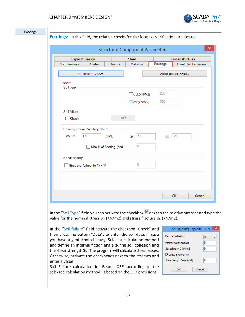
Footings: In this field, the relative checks for the footings verification are located
In the “Soil Type” field you can activate the checkbox next to the relative stresses and type the value for the nominal stress σal (ΚΝ/m2) and stress fracture σfr (ΚΝ/m2). In the “Soil failure” field activate the checkbox “Check” and then press the button “Data”, to enter the soil data, in case you have a geotechnical study. Select a calculation method and define an internal fiction angle φ, the soil cohesion and the shear strength Su. The program will calculate the stresses. Otherwise, activate the checkboxes next to the stresses and enter a value. Soil Failure calculation for Beams OEF, according to the selected calculation method, is based on the EC7 provisions.
CHAPTER 9 “MEMBERS DESIGN”
18
“Bending-Shear-Punching shear”: In this field activate the checkbox “Max H of Footing” and type a value. The activated checkbox means that the program will perform the design check against punching shear. If with the original height, the punching shear design check is not satisfied, the program will calculate the height that satisfies the check. If this is higher than the limit you have set, a message is displayed that informs you that a higher footing is necessary.
In the following fields “qx” and “qz” type the values of the coefficients used in the analysis. In the “Serviceability” field the design checks that correspond to the serviceability limit state are included. Activate the checkbox which allows the user to define the limit value of the considered ratio δcr/l.
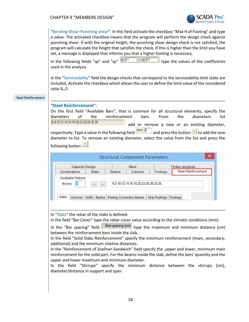
“Steel Reinforcement”: On the first field “Available Bars”, that is common for all structural elements, specify the diameters of the reinforcement bars. From the diameters list
add or remove a new or an existing diameter,
respectively. Type a value in the following field and press the button to add the new diameter to list. To remove an existing diameter, select the value from the list and press the
following button .
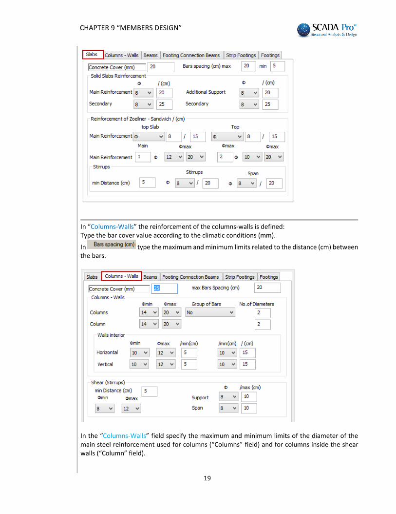
In “Slabs” the rebar of the slabs is defined: In the field “Bar Cover” type the rebar cover value according to the climatic conditions (mm).
In the “Bar spacing” field type the maximum and minimum distance (cm) between the reinforcement bars inside the slab. In the field “Solid Slabs Reinforcement” specify the minimum reinforcement (main, secondary, additional) and the minimum relative distances. In the “Reinforcement of Zoellner-Sandwich” field specify the ,upper and lower, minimum main reinforcement for the solid part. For the beams inside the slab, define the bars’ quantity and the upper and lower maximum and minimum diameter. In the field “Stirrups” specify the minimum distance between the stirrups (cm), diameter/distance in support and span.
CHAPTER 9 “MEMBERS DESIGN”
19
In “Columns-Walls” the reinforcement of the columns-walls is defined: Type the bar cover value according to the climatic conditions (mm).
In type the maximum and minimum limits related to the distance (cm) between the bars.
In the “Columns-Walls” field specify the maximum and minimum limits of the diameter of the main steel reinforcement used for columns (“Columns” field) and for columns inside the shear walls (“Column” field).
CHAPTER 9 “MEMBERS DESIGN”
20
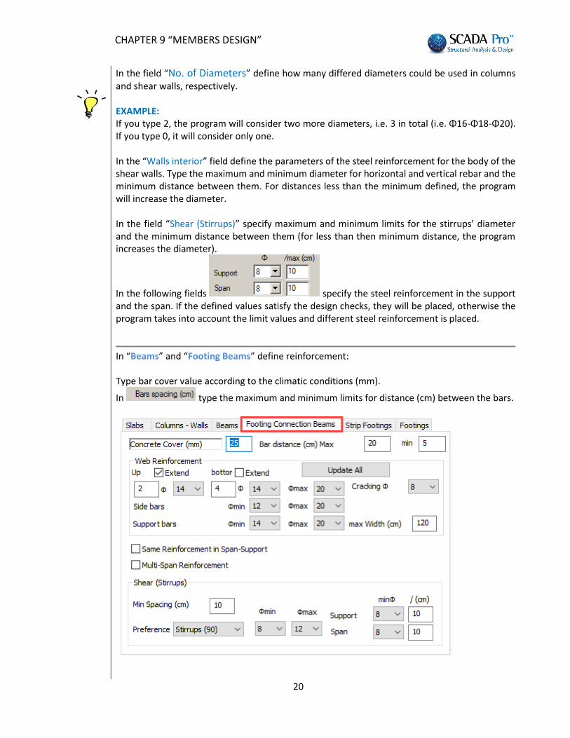
In the field “No. of Diameters” define how many differed diameters could be used in columns and shear walls, respectively. EXAMPLE: If you type 2, the program will consider two more diameters, i.e. 3 in total (i.e. Φ16-Φ18-Φ20). If you type 0, it will consider only one. In the “Walls interior” field define the parameters of the steel reinforcement for the body of the shear walls. Type the maximum and minimum diameter for horizontal and vertical rebar and the minimum distance between them. For distances less than the minimum defined, the program will increase the diameter. In the field “Shear (Stirrups)” specify maximum and minimum limits for the stirrups’ diameter and the minimum distance between them (for less than then minimum distance, the program increases the diameter).
In the following fields specify the steel reinforcement in the support and the span. If the defined values satisfy the design checks, they will be placed, otherwise the program takes into account the limit values and different steel reinforcement is placed.
In “Beams” and “Footing Beams” define reinforcement: Type bar cover value according to the climatic conditions (mm).
In type the maximum and minimum limits for distance (cm) between the bars.
CHAPTER 9 “MEMBERS DESIGN”
21
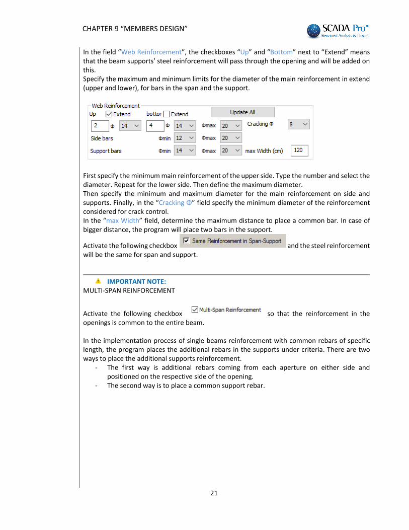
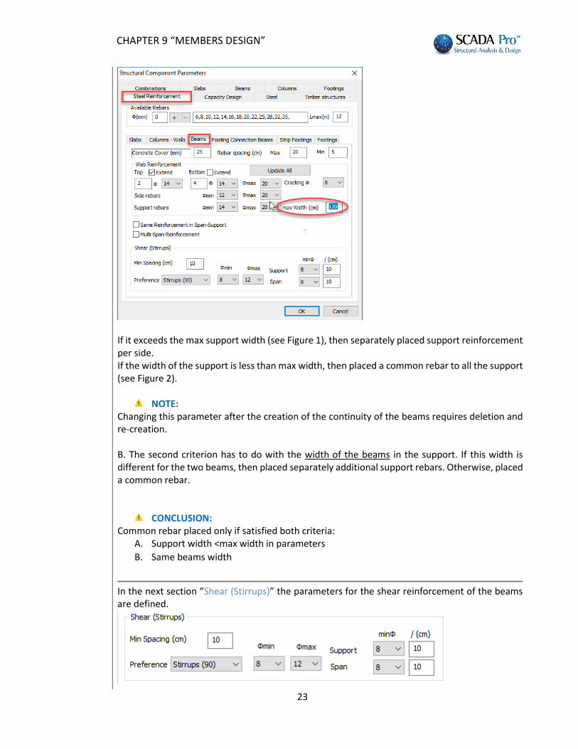
In the field “Web Reinforcement”, the checkboxes “Up” and “Bottom” next to “Extend” means that the beam supports’ steel reinforcement will pass through the opening and will be added on this. Specify the maximum and minimum limits for the diameter of the main reinforcement in extend (upper and lower), for bars in the span and the support.
First specify the minimum main reinforcement of the upper side. Type the number and select the diameter. Repeat for the lower side. Then define the maximum diameter. Then specify the minimum and maximum diameter for the main reinforcement on side and supports. Finally, in the “Cracking Φ” field specify the minimum diameter of the reinforcement considered for crack control. In the “max Width” field, determine the maximum distance to place a common bar. In case of bigger distance, the program will place two bars in the support.
Activate the following checkbox and the steel reinforcement will be the same for span and support.
IMPORTANT NOTE:
MULTI-SPAN REINFORCEMENT
Activate the following checkbox so that the reinforcement in the openings is common to the entire beam. In the implementation process of single beams reinforcement with common rebars of specific length, the program places the additional rebars in the supports under criteria. There are two ways to place the additional supports reinforcement.
- The first way is additional rebars coming from each aperture on either side and positioned on the respective side of the opening.
- The second way is to place a common support rebar.
CHAPTER 9 “MEMBERS DESIGN”
22
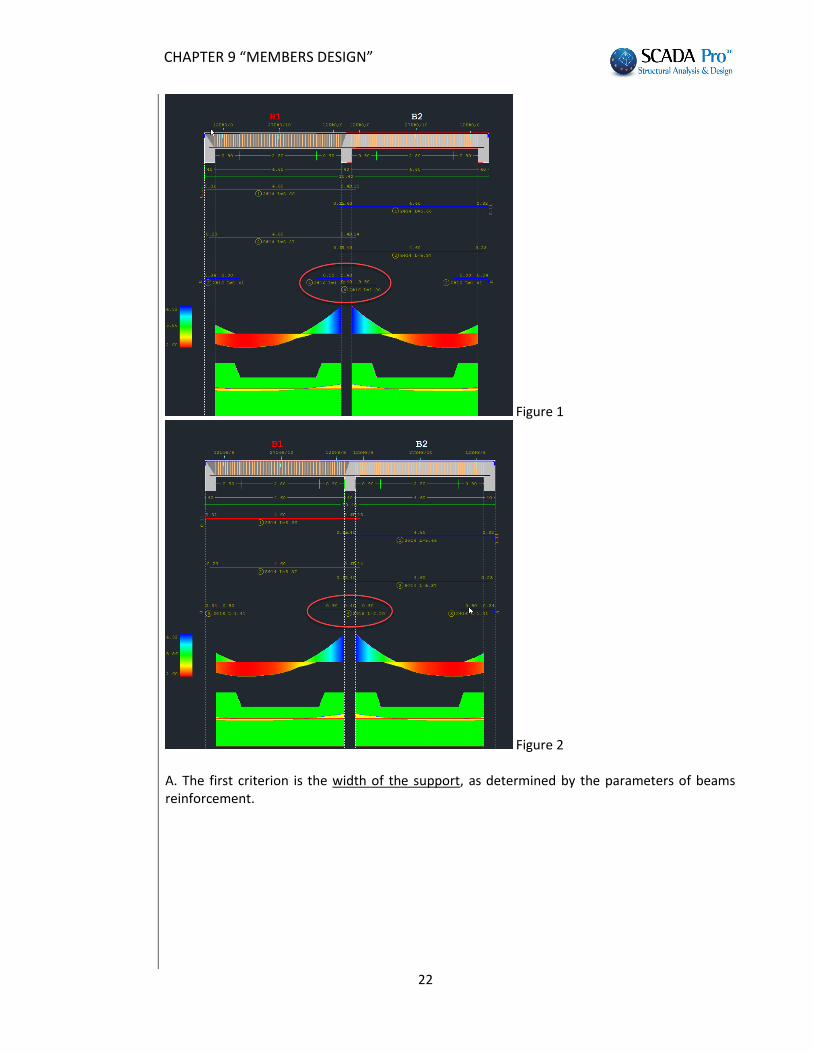
Figure 1
Figure 2 Α. The first criterion is the width of the support, as determined by the parameters of beams reinforcement.
CHAPTER 9 “MEMBERS DESIGN”
23
If it exceeds the max support width (see Figure 1), then separately placed support reinforcement per side. If the width of the support is less than max width, then placed a common rebar to all the support (see Figure 2).
NOTE: Changing this parameter after the creation of the continuity of the beams requires deletion and re-creation. Β. The second criterion has to do with the width of the beams in the support. If this width is different for the two beams, then placed separately additional support rebars. Otherwise, placed a common rebar.
CONCLUSION: Common rebar placed only if satisfied both criteria:
A. Support width <max width in parameters
B. Same beams width
In the next section “Shear (Stirrups)” the parameters for the shear reinforcement of the beams are defined.
CHAPTER 9 “MEMBERS DESIGN”
24
Specify, the minimum distance between the stirrups the angle (if they are placed perpendicularly or obliquely (45ο)) the diameter limit values
In the following fields specify the diameter and the distance of the reinforcement bars in the support and the span. If these values satisfy the design checks, the rebar is placed as appropriate, otherwise the program places a different reinforcement by taking into account the limit values of the diameter as well as the distance.
NOTE:
: After completing the parameter selections and before closing the window, press the Update All button to update the parameters.
In “Strip Footing” the parameters of the steel reinforcement in strip footings are defined: For the common parameters mentioned in the previous tabs, follow the previous described procedure. In addition, in the “Range Reinforcement” field define the limits for longitudinal and transversal
flange reinforcement.
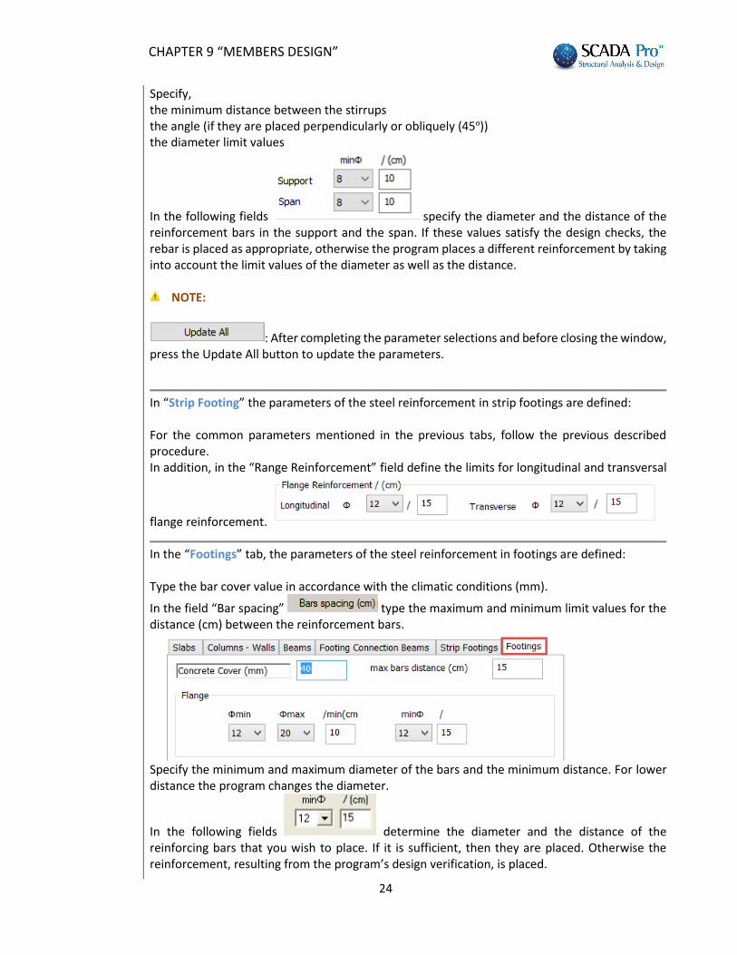
In the “Footings” tab, the parameters of the steel reinforcement in footings are defined: Type the bar cover value in accordance with the climatic conditions (mm).
In the field “Bar spacing” type the maximum and minimum limit values for the distance (cm) between the reinforcement bars.
Specify the minimum and maximum diameter of the bars and the minimum distance. For lower distance the program changes the diameter.
In the following fields determine the diameter and the distance of the reinforcing bars that you wish to place. If it is sufficient, then they are placed. Otherwise the reinforcement, resulting from the program’s design verification, is placed.
CHAPTER 9 “MEMBERS DESIGN”
25
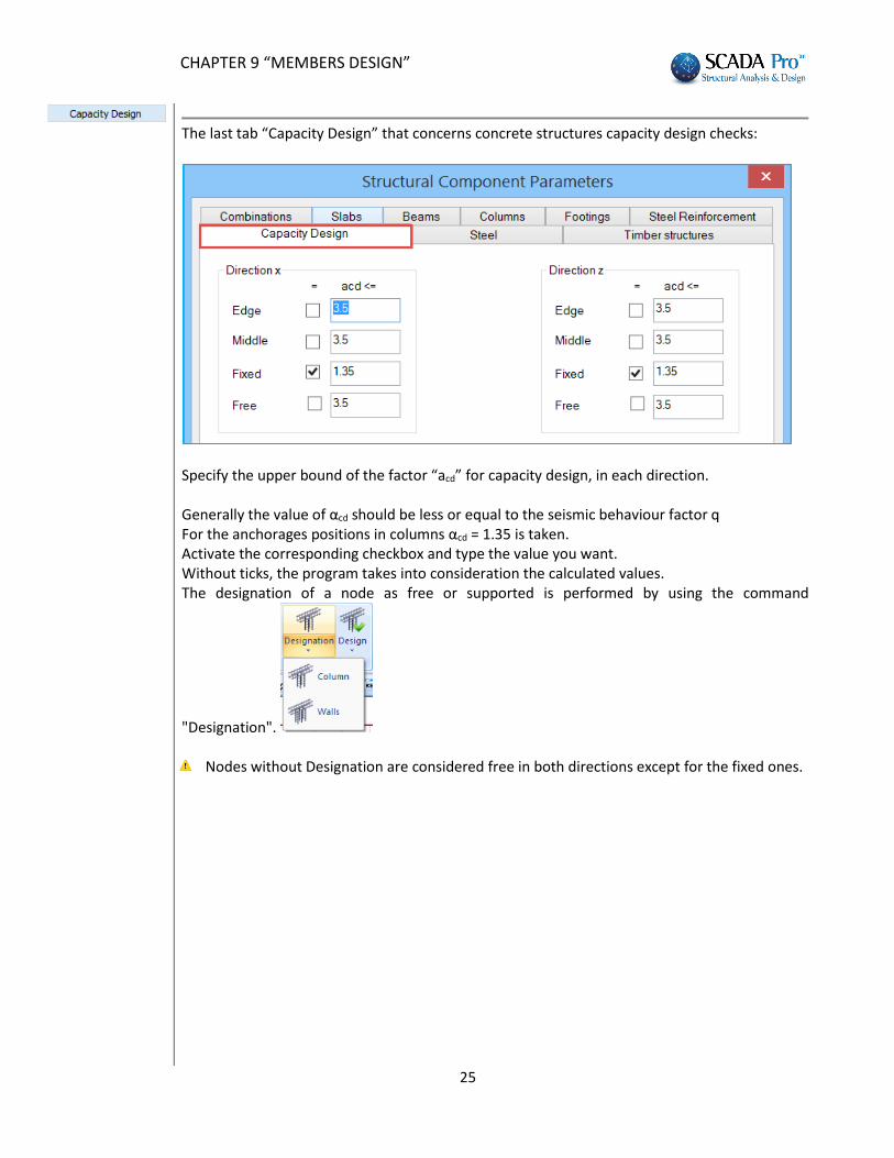
The last tab “Capacity Design” that concerns concrete structures capacity design checks:
Specify the upper bound of the factor “acd” for capacity design, in each direction. Generally the value of αcd should be less or equal to the seismic behaviour factor q For the anchorages positions in columns αcd = 1.35 is taken. Activate the corresponding checkbox and type the value you want. Without ticks, the program takes into consideration the calculated values. The designation of a node as free or supported is performed by using the command
"Designation".
Nodes without Designation are considered free in both directions except for the fixed ones.
CHAPTER 9 “MEMBERS DESIGN”
26
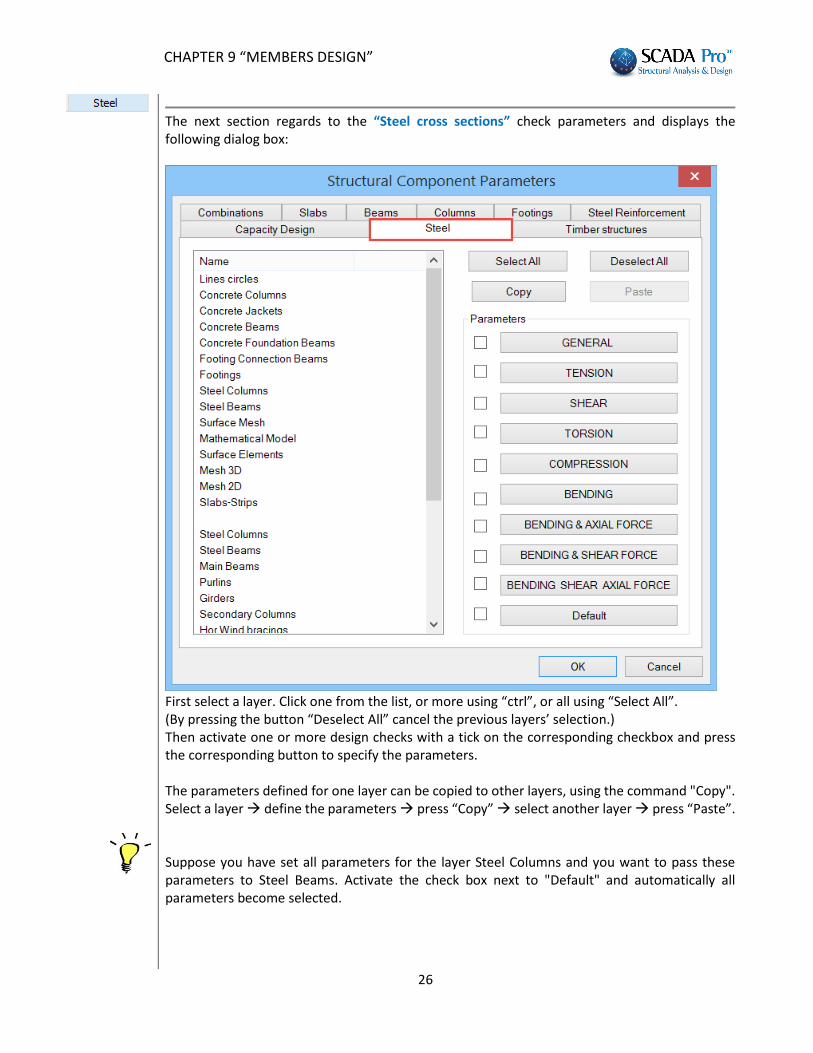
The next section regards to the “Steel cross sections” check parameters and displays the following dialog box:
First select a layer. Click one from the list, or more using “ctrl”, or all using “Select All”. (By pressing the button “Deselect All” cancel the previous layers’ selection.) Then activate one or more design checks with a tick on the corresponding checkbox and press the corresponding button to specify the parameters. The parameters defined for one layer can be copied to other layers, using the command "Copy". Select a layer define the parameters press “Copy” select another layer press “Paste”. Suppose you have set all parameters for the layer Steel Columns and you want to pass these parameters to Steel Beams. Activate the check box next to "Default" and automatically all parameters become selected.
CHAPTER 9 “MEMBERS DESIGN”
27
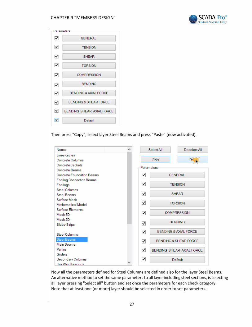
Then press “Copy”, select layer Steel Beams and press “Paste” (now activated).
Now all the parameters defined for Steel Columns are defined also for the layer Steel Beams. An alternative method to set the same parameters to all layer including steel sections, is selecting all layer pressing "Select all" button and set once the parameters for each check category. Note that at least one (or more) layer should be selected in order to set parameters.
CHAPTER 9 “MEMBERS DESIGN”
28
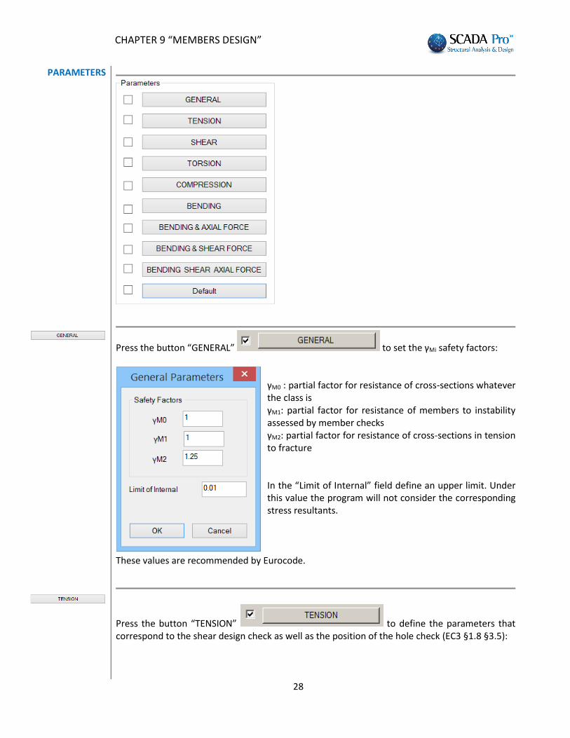
PARAMETERS
Press the button “GENERAL” to set the γMi safety factors:
γM0 : partial factor for resistance of cross-sections whatever the class is γM1: partial factor for resistance of members to instability assessed by member checks γM2: partial factor for resistance of cross-sections in tension to fracture In the “Limit of Internal” field define an upper limit. Under this value the program will not consider the corresponding stress resultants.
These values are recommended by Eurocode.
Press the button “TENSION” to define the parameters that correspond to the shear design check as well as the position of the hole check (EC3 §1.8 §3.5):
CHAPTER 9 “MEMBERS DESIGN”
29
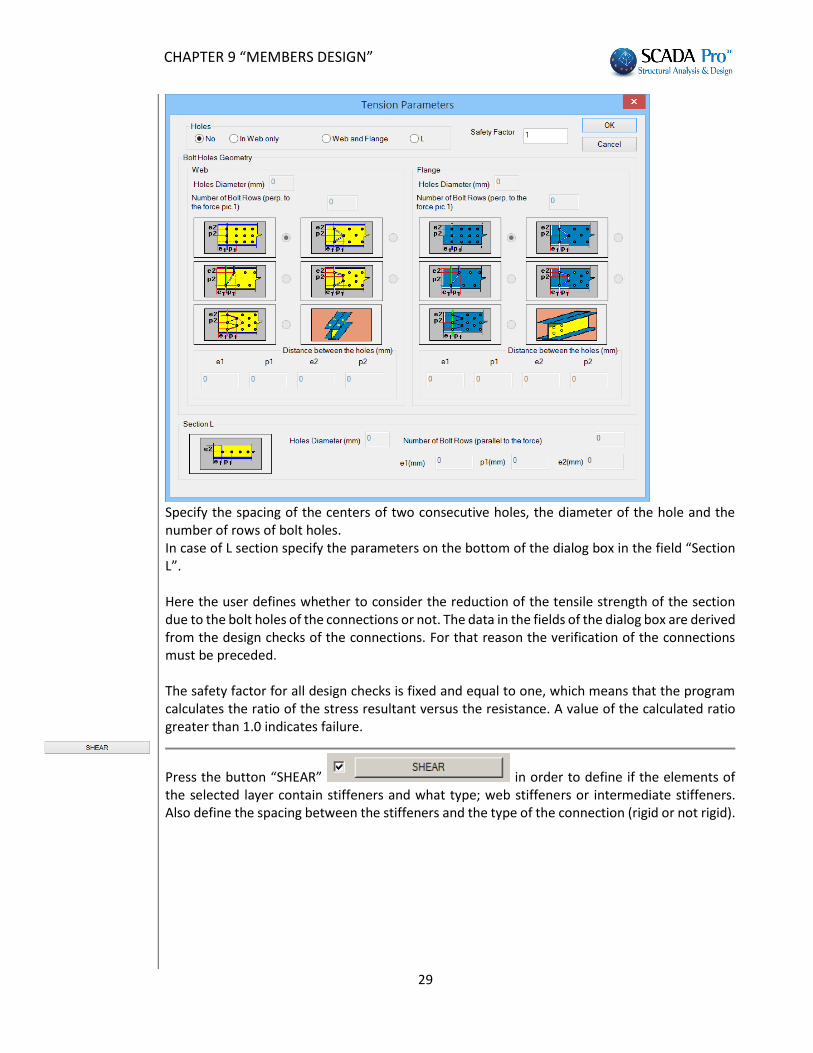
Specify the spacing of the centers of two consecutive holes, the diameter of the hole and the number of rows of bolt holes. In case of L section specify the parameters on the bottom of the dialog box in the field “Section L”. Here the user defines whether to consider the reduction of the tensile strength of the section due to the bolt holes of the connections or not. The data in the fields of the dialog box are derived from the design checks of the connections. For that reason the verification of the connections must be preceded. The safety factor for all design checks is fixed and equal to one, which means that the program calculates the ratio of the stress resultant versus the resistance. A value of the calculated ratio greater than 1.0 indicates failure.
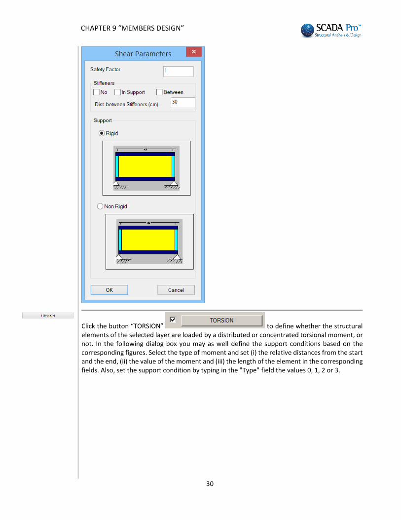
Press the button “SHEAR” in order to define if the elements of the selected layer contain stiffeners and what type; web stiffeners or intermediate stiffeners. Also define the spacing between the stiffeners and the type of the connection (rigid or not rigid).
CHAPTER 9 “MEMBERS DESIGN”
30
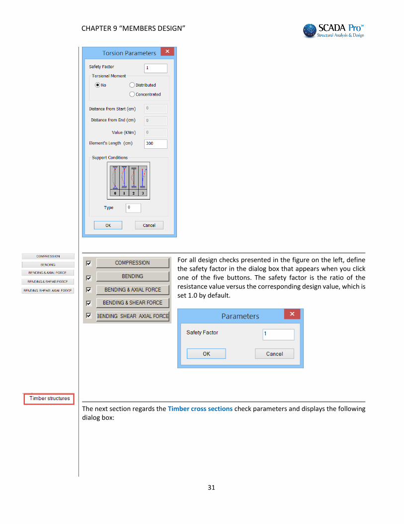
Click the button “TORSION” to define whether the structural elements of the selected layer are loaded by a distributed or concentrated torsional moment, or not. In the following dialog box you may as well define the support conditions based on the corresponding figures. Select the type of moment and set (i) the relative distances from the start and the end, (ii) the value of the moment and (iii) the length of the element in the corresponding fields. Also, set the support condition by typing in the "Type" field the values 0, 1, 2 or 3.
CHAPTER 9 “MEMBERS DESIGN”
31
For all design checks presented in the figure on the left, define the safety factor in the dialog box that appears when you click one of the five buttons. The safety factor is the ratio of the resistance value versus the corresponding design value, which is set 1.0 by default.
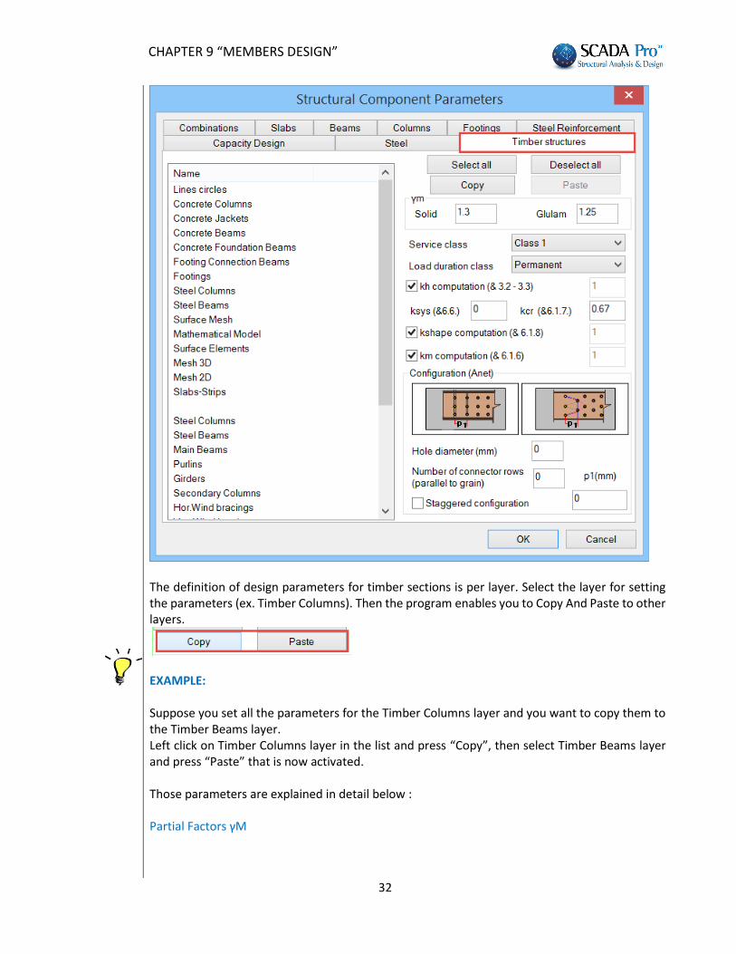
The next section regards the Timber cross sections check parameters and displays the following dialog box:
CHAPTER 9 “MEMBERS DESIGN”
32
The definition of design parameters for timber sections is per layer. Select the layer for setting the parameters (ex. Timber Columns). Then the program enables you to Copy And Paste to other layers.
EXAMPLE: Suppose you set all the parameters for the Timber Columns layer and you want to copy them to the Timber Beams layer. Left click on Timber Columns layer in the list and press “Copy”, then select Timber Beams layer and press “Paste” that is now activated. Those parameters are explained in detail below : Partial Factors γΜ
CHAPTER 9 “MEMBERS DESIGN”
33
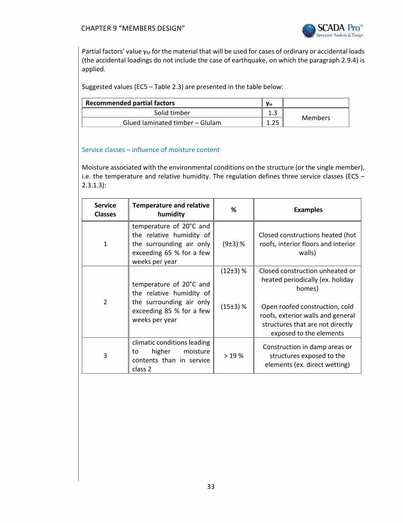
Partial factors’ value γM for the material that will be used for cases of ordinary or accidental loads (the accidental loadings do not include the case of earthquake, on which the paragraph 2.9.4) is applied. Suggested values (EC5 – Table 2.3) are presented in the table below:
Service classes – influence of moisture content Moisture associated with the environmental conditions on the structure (or the single member), i.e. the temperature and relative humidity. The regulation defines three service classes (EC5 – 2.3.1.3):
Service Classes
Temperature and relative humidity
% Examples
1
temperature of 20°C and the relative humidity of the surrounding air only exceeding 65 % for a few weeks per year
(9±3) % Closed constructions heated (hot roofs, interior floors and interior
walls)
2
temperature of 20°C and the relative humidity of the surrounding air only exceeding 85 % for a few weeks per year
(12±3) % Closed construction unheated or heated periodically (ex. holiday
homes)
(15±3) % Open roofed construction, cold roofs, exterior walls and general structures that are not directly
exposed to the elements
3
climatic conditions leading to higher moisture contents than in service class 2
> 19 % Construction in damp areas or
structures exposed to the elements (ex. direct wetting)
Recommended partial factors γΜ
Solid timber 1.3 Members
Glued laminated timber – Glulam 1.25
CHAPTER 9 “MEMBERS DESIGN”
34
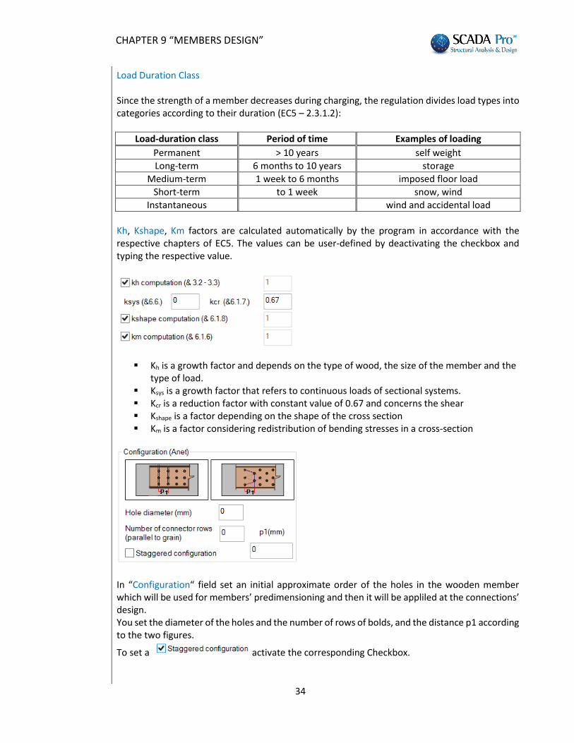
Load Duration Class Since the strength of a member decreases during charging, the regulation divides load types into categories according to their duration (EC5 – 2.3.1.2):
Load-duration class Period of time Examples of loading
Permanent > 10 years self weight
Long-term 6 months to 10 years storage
Medium-term 1 week to 6 months imposed floor load
Short-term to 1 week snow, wind
Instantaneous wind and accidental load
Kh, Kshape, Km factors are calculated automatically by the program in accordance with the respective chapters of EC5. The values can be user-defined by deactivating the checkbox and typing the respective value.
Κh is a growth factor and depends on the type of wood, the size of the member and the type of load.
Ksys is a growth factor that refers to continuous loads of sectional systems. Kcr is a reduction factor with constant value of 0.67 and concerns the shear Kshape is a factor depending on the shape of the cross section Km is a factor considering redistribution of bending stresses in a cross-section
In “Configuration“ field set an initial approximate order of the holes in the wooden member which will be used for members’ predimensioning and then it will be appliled at the connections’ design. You set the diameter of the holes and the number of rows of bolds, and the distance p1 according to the two figures.
To set a activate the corresponding Checkbox.
CHAPTER 9 “MEMBERS DESIGN”
35
1.2. Beams
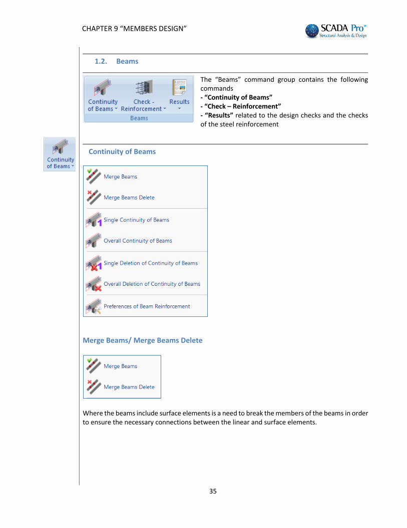
The “Beams” command group contains the following commands - “Continuity of Beams” - “Check – Reinforcement” - “Results” related to the design checks and the checks of the steel reinforcement
Continuity of Beams
Merge Beams/ Merge Beams Delete
Where the beams include surface elements is a need to break the members of the beams in order to ensure the necessary connections between the linear and surface elements.
CHAPTER 9 “MEMBERS DESIGN”
36
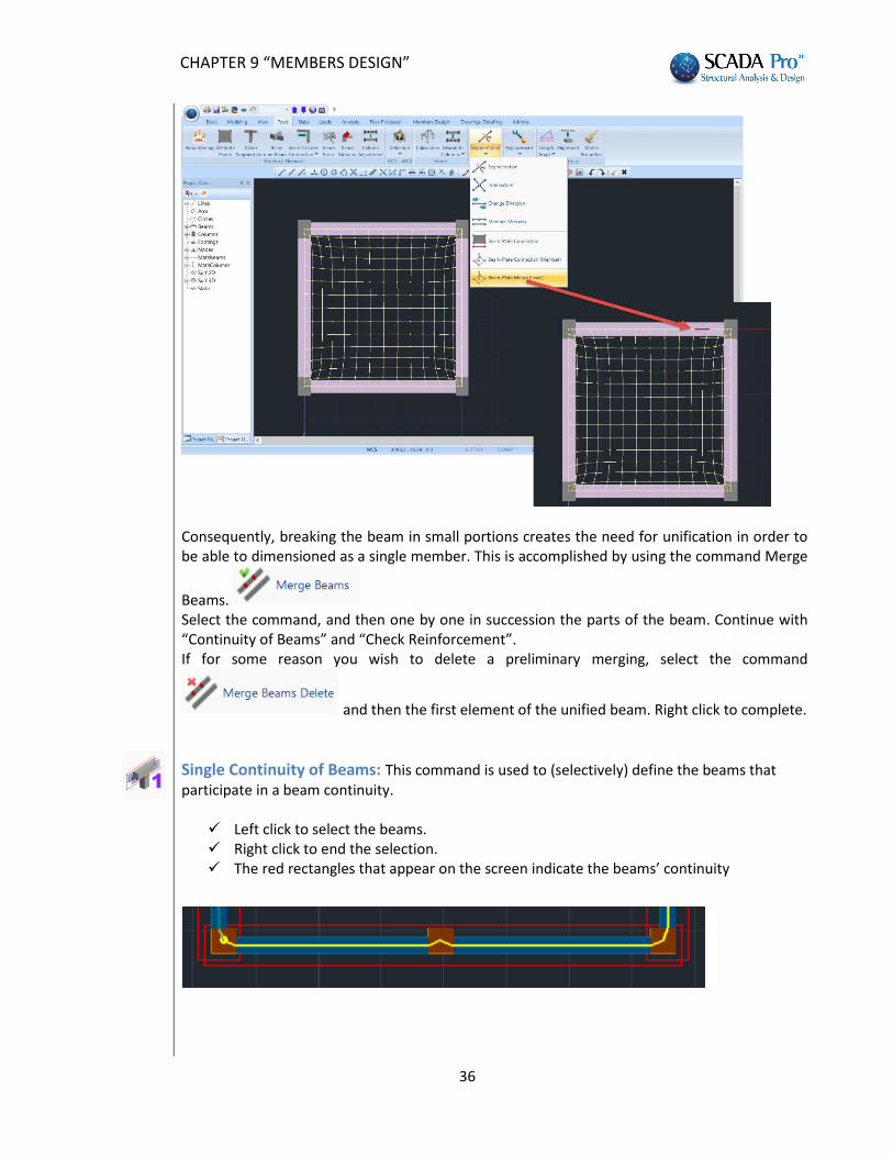
Consequently, breaking the beam in small portions creates the need for unification in order to be able to dimensioned as a single member. This is accomplished by using the command Merge
Beams. Select the command, and then one by one in succession the parts of the beam. Continue with “Continuity of Beams” and “Check Reinforcement”. If for some reason you wish to delete a preliminary merging, select the command
and then the first element of the unified beam. Right click to complete.
Single Continuity of Beams: This command is used to (selectively) define the beams that participate in a beam continuity.
Left click to select the beams. Right click to end the selection. The red rectangles that appear on the screen indicate the beams’ continuity
CHAPTER 9 “MEMBERS DESIGN”
37
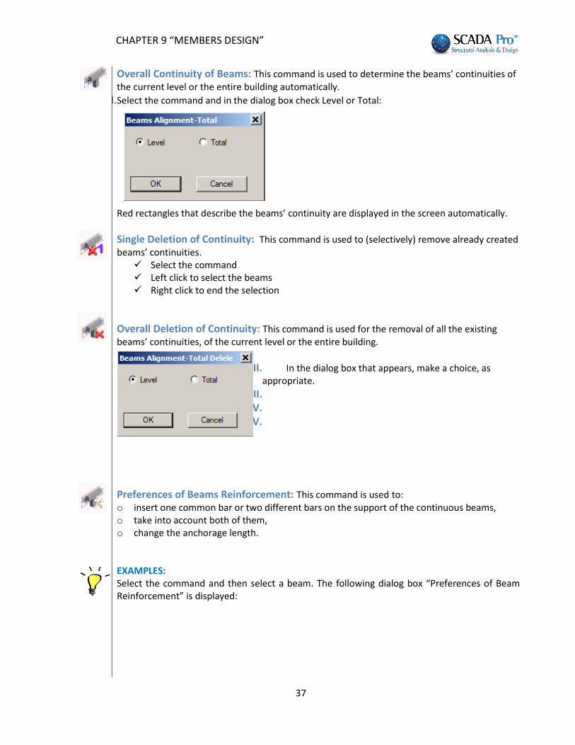
Overall Continuity of Beams: This command is used to determine the beams’ continuities of the current level or the entire building automatically.
I.Select the command and in the dialog box check Level or Total:
Red rectangles that describe the beams’ continuity are displayed in the screen automatically.
Single Deletion of Continuity: This command is used to (selectively) remove already created beams’ continuities.
Select the command Left click to select the beams Right click to end the selection
Overall Deletion of Continuity: This command is used for the removal of all the existing beams’ continuities, of the current level or the entire building.
II. In the dialog box that appears, make a choice, as appropriate.
III. IV. V.
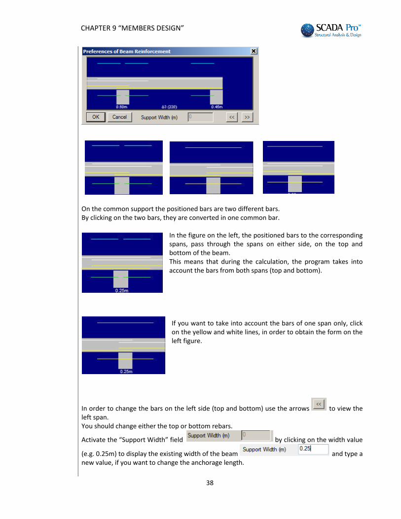
Preferences of Beams Reinforcement: This command is used to: o insert one common bar or two different bars on the support of the continuous beams, o take into account both of them, o change the anchorage length. EXAMPLES: Select the command and then select a beam. The following dialog box “Preferences of Beam Reinforcement” is displayed:
CHAPTER 9 “MEMBERS DESIGN”
38
On the common support the positioned bars are two different bars. By clicking on the two bars, they are converted in one common bar.
In the figure on the left, the positioned bars to the corresponding spans, pass through the spans on either side, on the top and bottom of the beam. This means that during the calculation, the program takes into account the bars from both spans (top and bottom).
If you want to take into account the bars of one span only, click on the yellow and white lines, in order to obtain the form on the left figure.
In order to change the bars on the left side (top and bottom) use the arrows to view the left span. You should change either the top or bottom rebars.
Activate the “Support Width” field by clicking on the width value
(e.g. 0.25m) to display the existing width of the beam and type a new value, if you want to change the anchorage length.
CHAPTER 9 “MEMBERS DESIGN”
39
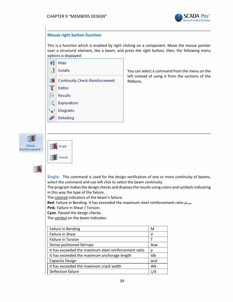
Mouse right button function
This is a function which is enabled by right clicking on a component. Move the mouse pointer over a structural element, like a beam, and press the right button, then, the following menu options is displayed:
You can select a command from the menu on the left instead of using it from the sections of the Ribbons.
Single: This command is used for the design verification of one or more continuity of beams, select the command and use left click to select the beam continuity. The program makes the design checks and displays the results using colors and symbols indicating in this way the type of the failure. The colored indicators of the beam’s failure: Red. Failure in Bending. It has exceeded the maximum steel reinforcement ratio ρmax. Pink. Failure in Shear / Torsion. Cyan. Passed the design checks. The symbol on the beam indicates:
Failure in Bending Μ
Failure in Shear V
Failure in Torsion T
Dense positioned Stirrups Αsw
It has exceeded the maximum steel reinforcement ratio ρ
It has exceeded the maximum anchorage length ldb
Capacity Design αcd
It has exceeded the maximum crack width Wk
Deflection failure L/d
CHAPTER 9 “MEMBERS DESIGN”
40
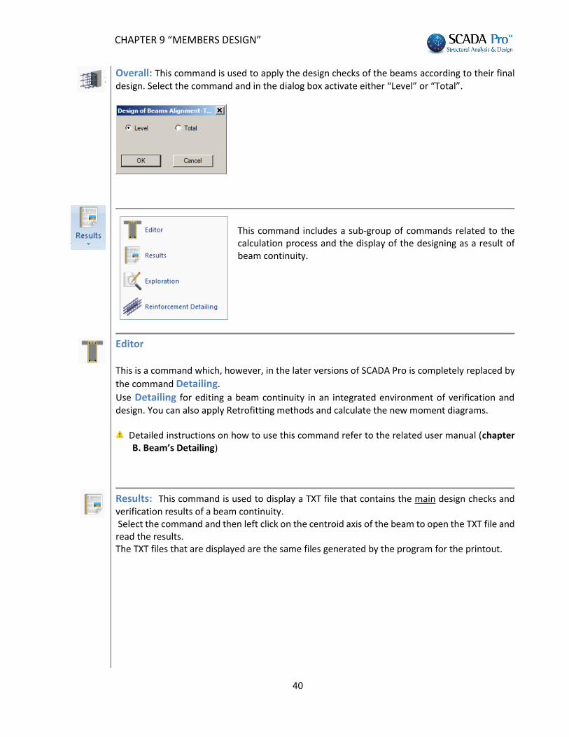
Overall: This command is used to apply the design checks of the beams according to their final design. Select the command and in the dialog box activate either “Level” or “Total”.
This command includes a sub-group of commands related to the calculation process and the display of the designing as a result of beam continuity.
Editor This is a command which, however, in the later versions of SCADA Pro is completely replaced by
the command Detailing.
Use Detailing for editing a beam continuity in an integrated environment of verification and design. You can also apply Retrofitting methods and calculate the new moment diagrams.
Detailed instructions on how to use this command refer to the related user manual (chapter B. Beam’s Detailing)
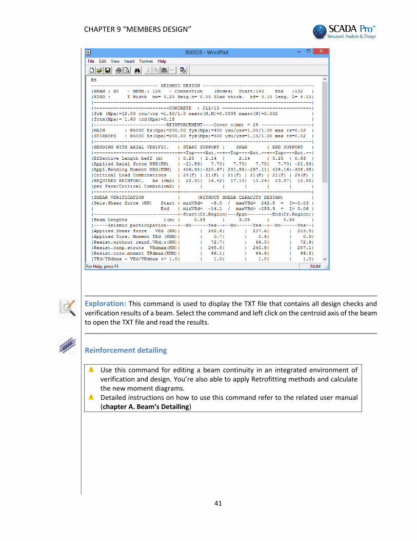
Results: This command is used to display a TXT file that contains the main design checks and verification results of a beam continuity. Select the command and then left click on the centroid axis of the beam to open the TXT file and read the results. The TXT files that are displayed are the same files generated by the program for the printout.
CHAPTER 9 “MEMBERS DESIGN”
41
Exploration: This command is used to display the TXT file that contains all design checks and verification results of a beam. Select the command and left click on the centroid axis of the beam to open the TXT file and read the results.
Reinforcement detailing
Use this command for editing a beam continuity in an integrated environment of verification and design. You’re also able to apply Retrofitting methods and calculate the new moment diagrams.
Detailed instructions on how to use this command refer to the related user manual (chapter A. Beam’s Detailing)
CHAPTER 9 “MEMBERS DESIGN”
42
1.3. Capacity design
The command group “Capacity Design” contains commands for performing capacity design.
Capacity Design always precedes columns and walls dimensioning where necessary.
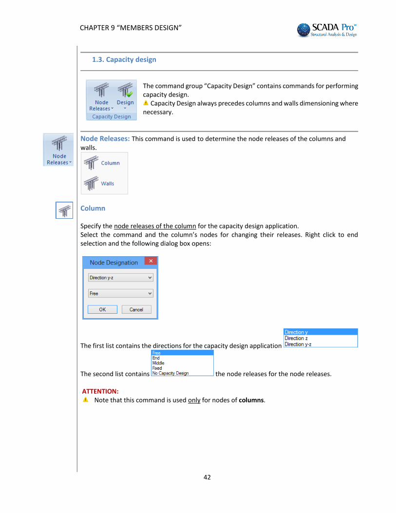
Node Releases: This command is used to determine the node releases of the columns and walls.
Column Specify the node releases of the column for the capacity design application. Select the command and the column’s nodes for changing their releases. Right click to end selection and the following dialog box opens:
The first list contains the directions for the capacity design application
The second list contains the node releases for the node releases. ATTENTION:
Note that this command is used only for nodes of columns.
CHAPTER 9 “MEMBERS DESIGN”
43
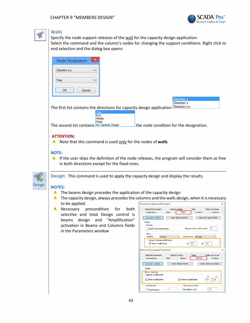
Walls Specify the node support releases of the wall for the capacity design application. Select the command and the column’s nodes for changing the support conditions. Right click to end selection and the dialog box opens:
The first list contains the directions for capacity design application
The second list contains the node condition for the designation. ATTENTION:
Note that this command is used only for the nodes of walls.
NOTE: If the user skips the definition of the node releases, the program will consider them as free
in both directions except for the fixed ones.
Design: This command is used to apply the capacity design and display the results. NOTES:
Τhe beams design precedes the application of the capacity design The capacity design, always precedes the columns and the walls design, when it is necessary
to be applied. Necessary precondition for both
selective and total Design control is beams design and "Amplification" activation in Beams and Columns fields in the Parameters window
CHAPTER 9 “MEMBERS DESIGN”
44
Single This command is used to apply capacity design on a single node. Select the command and left click on the node.
Overall This command is used to apply capacity design on every node of the current level. Select the command and repeat for the other levels.
Results This command is used for the display of the TXT file that contains the results of the main design checks of the capacity design. Select the command and left click on the node to open the TXT file and read the results.
Exploration This command is used for the display of the TXT file that contains all the results of the design checks of the capacity design. Select the command and left click on the node to open the TXT file and read the results.
1.4. Columns
The command group “Columns” contains commands about buckling check, design checks, steel reinforcement checks and results for columns and shear walls.
Columns and walls dimensioning always follows the capacity design; when it is necessary to
be applied. First the capacity design is applied on every required level, and then the design checks for columns and walls are performed.
Buckling: This command will be fully available in the next version.
Check Reinforcement: This is a command list related to the design checks for columns and walls resulting to their final dimensions.
Single: Select the command and left click to select one or more columns or walls. The program performs the appropriate design checks and displays the results by colors and symbols indicating the type of failure. A colored dot is displayed in the center of the element. The color changes according to the type of failure as follows:
Red: Failure caused by biaxial bending. The steel reinforcement exceeded the maximum ratio of 4%. Dense stirrups. No results are displayed.
CHAPTER 9 “MEMBERS DESIGN”
45
Pink: Failure by Shear / Torsion or exceedance of the ductility level. The results show the reason of failure. Cyan: All design checks are verified.
The initially indicated type of failure appears above the element as well:
Failure by biaxial bending M-N
Failure by Shear V
Confinement failure ωwd
Buckling failure λ
Failure by Torsion T
Dense Stirrups Αsw
Exceedance of 4% steel reinforcement ratio ρ
Exceedance of the ductility index ν
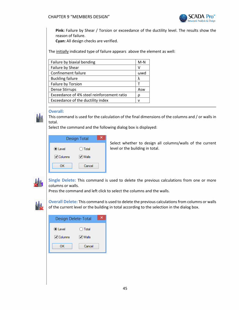
Overall: This command is used for the calculation of the final dimensions of the columns and / or walls in total. Select the command and the following dialog box is displayed:
Select whether to design all columns/walls of the current level or the building in total.
Single Delete: This command is used to delete the previous calculations from one or more columns or walls. Press the command and left click to select the columns and the walls.
Overall Delete: This command is used to delete the previous calculations from columns or walls of the current level or the building in total according to the selection in the dialog box.
CHAPTER 9 “MEMBERS DESIGN”
46
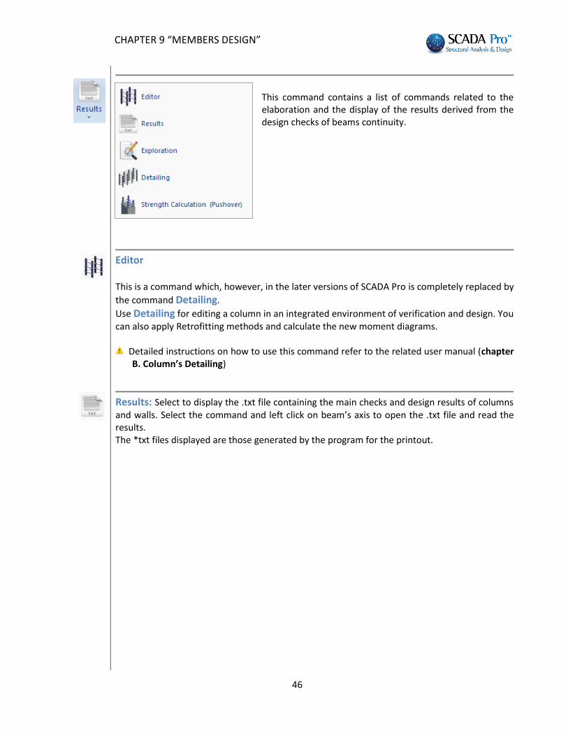
This command contains a list of commands related to the elaboration and the display of the results derived from the design checks of beams continuity.
Editor This is a command which, however, in the later versions of SCADA Pro is completely replaced by
the command Detailing.
Use Detailing for editing a column in an integrated environment of verification and design. You can also apply Retrofitting methods and calculate the new moment diagrams.
Detailed instructions on how to use this command refer to the related user manual (chapter B. Column’s Detailing)
Results: Select to display the .txt file containing the main checks and design results of columns and walls. Select the command and left click on beam’s axis to open the .txt file and read the results. The *txt files displayed are those generated by the program for the printout.
CHAPTER 9 “MEMBERS DESIGN”
47
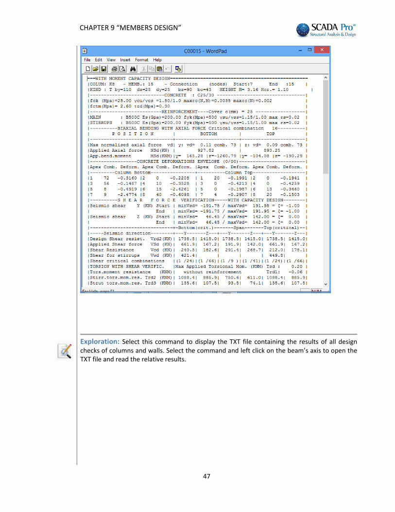
Exploration: Select this command to display the TXT file containing the results of all design checks of columns and walls. Select the command and left click on the beam’s axis to open the TXT file and read the relative results.
CHAPTER 9 “MEMBERS DESIGN”
48
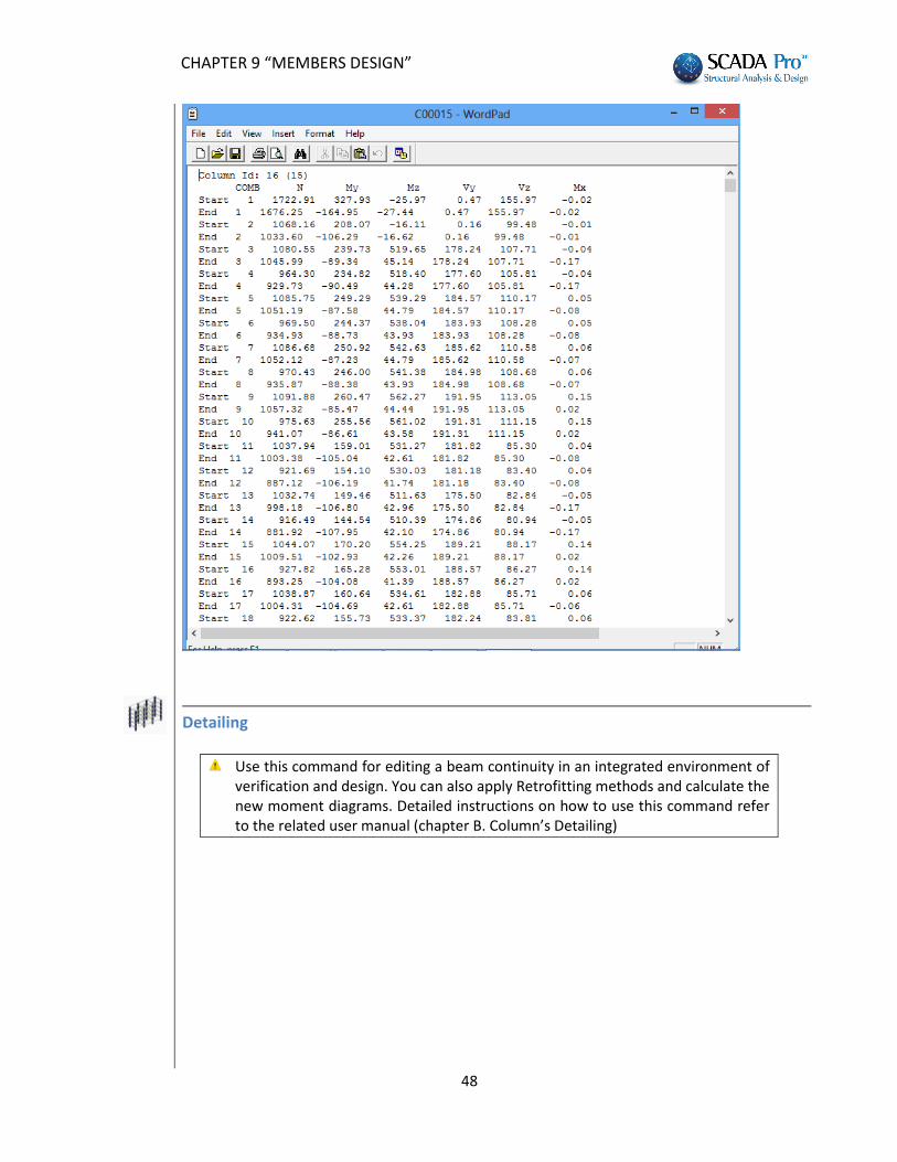
Detailing
Use this command for editing a beam continuity in an integrated environment of verification and design. You can also apply Retrofitting methods and calculate the new moment diagrams. Detailed instructions on how to use this command refer to the related user manual (chapter B. Column’s Detailing)
CHAPTER 9 “MEMBERS DESIGN”
49
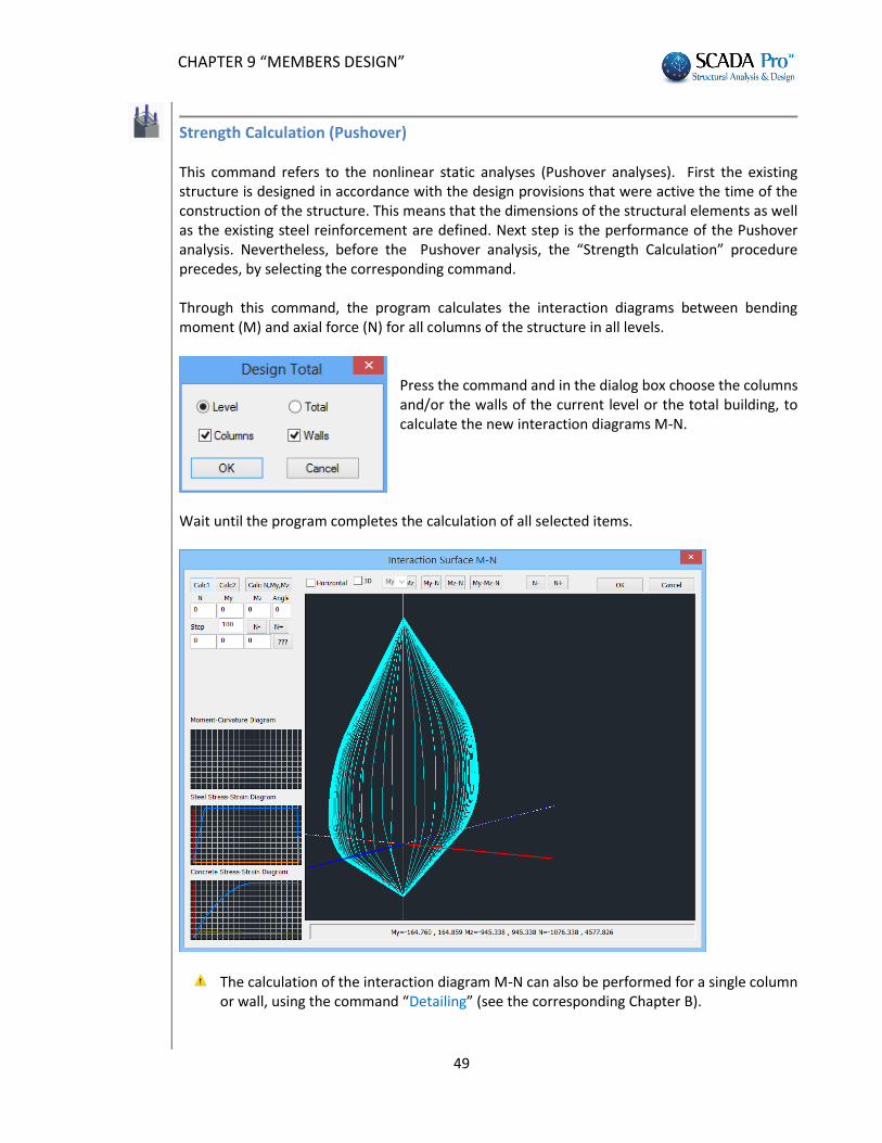
Strength Calculation (Pushover) This command refers to the nonlinear static analyses (Pushover analyses). First the existing structure is designed in accordance with the design provisions that were active the time of the construction of the structure. This means that the dimensions of the structural elements as well as the existing steel reinforcement are defined. Next step is the performance of the Pushover analysis. Nevertheless, before the Pushover analysis, the “Strength Calculation” procedure precedes, by selecting the corresponding command. Through this command, the program calculates the interaction diagrams between bending moment (M) and axial force (N) for all columns of the structure in all levels.
Press the command and in the dialog box choose the columns and/or the walls of the current level or the total building, to calculate the new interaction diagrams M-N.
Wait until the program completes the calculation of all selected items.
The calculation of the interaction diagram M-N can also be performed for a single column or wall, using the command “Detailing” (see the corresponding Chapter B).
CHAPTER 9 “MEMBERS DESIGN”
50
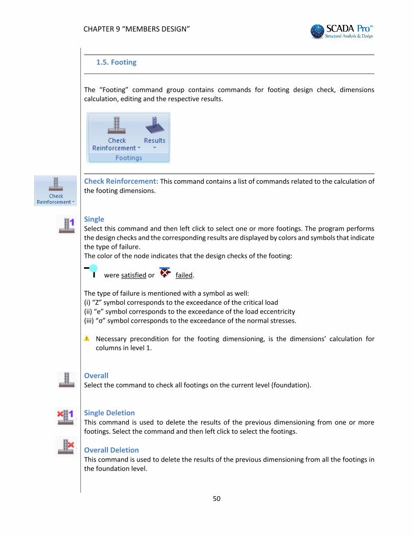
1.5. Footing
The “Footing” command group contains commands for footing design check, dimensions calculation, editing and the respective results.
Check Reinforcement: This command contains a list of commands related to the calculation of the footing dimensions.
Single Select this command and then left click to select one or more footings. The program performs the design checks and the corresponding results are displayed by colors and symbols that indicate the type of failure. The color of the node indicates that the design checks of the footing:
were satisfied or failed. The type of failure is mentioned with a symbol as well: (i) “Z” symbol corresponds to the exceedance of the critical load (ii) “e” symbol corresponds to the exceedance of the load eccentricity (iii) “σ” symbol corresponds to the exceedance of the normal stresses.
Necessary precondition for the footing dimensioning, is the dimensions’ calculation for columns in level 1.
Overall Select the command to check all footings on the current level (foundation).
Single Deletion This command is used to delete the results of the previous dimensioning from one or more footings. Select the command and then left click to select the footings.
Overall Deletion This command is used to delete the results of the previous dimensioning from all the footings in the foundation level.
CHAPTER 9 “MEMBERS DESIGN”
51
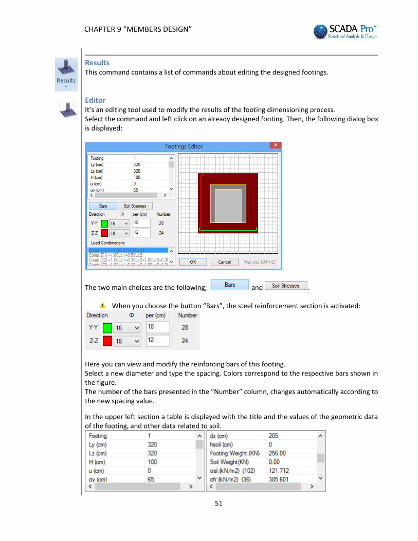
Results This command contains a list of commands about editing the designed footings.
Editor It’s an editing tool used to modify the results of the footing dimensioning process. Select the command and left click on an already designed footing. Then, the following dialog box is displayed:
The two main choices are the following; and .
When you choose the button “Bars”, the steel reinforcement section is activated:
Here you can view and modify the reinforcing bars of this footing. Select a new diameter and type the spacing. Colors correspond to the respective bars shown in the figure. The number of the bars presented in the “Number” column, changes automatically according to the new spacing value.
In the upper left section a table is displayed with the title and the values of the geometric data of the footing, and other data related to soil.
CHAPTER 9 “MEMBERS DESIGN”
52
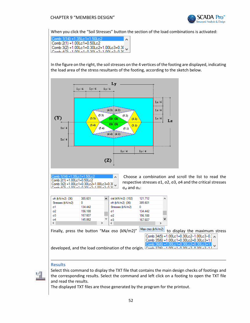
When you click the “Soil Stresses” button the section of the load combinations is activated: In the figure on the right, the soil stresses on the 4 vertices of the footing are displayed, indicating the load area of the stress resultants of the footing, according to the sketch below.
Choose a combination and scroll the list to read the respective stresses σ1, σ2, σ3, σ4 and the critical stresses σal and σfr:
Finally, press the button “Max σso (kN/m2)” to display the maximum stress
developed, and the load combination of the origin.
Results Select this command to display the TXT file that contains the main design checks of footings and the corresponding results. Select the command and left click on a footing to open the TXT file and read the results. The displayed TXT files are those generated by the program for the printout.
CHAPTER 9 “MEMBERS DESIGN”
53
Exploration Select this command to display the TXT file that contains all design checks for footings and the corresponding results. Select the command and left click on the beam’s centroid axis to open the TXT file and read the results.
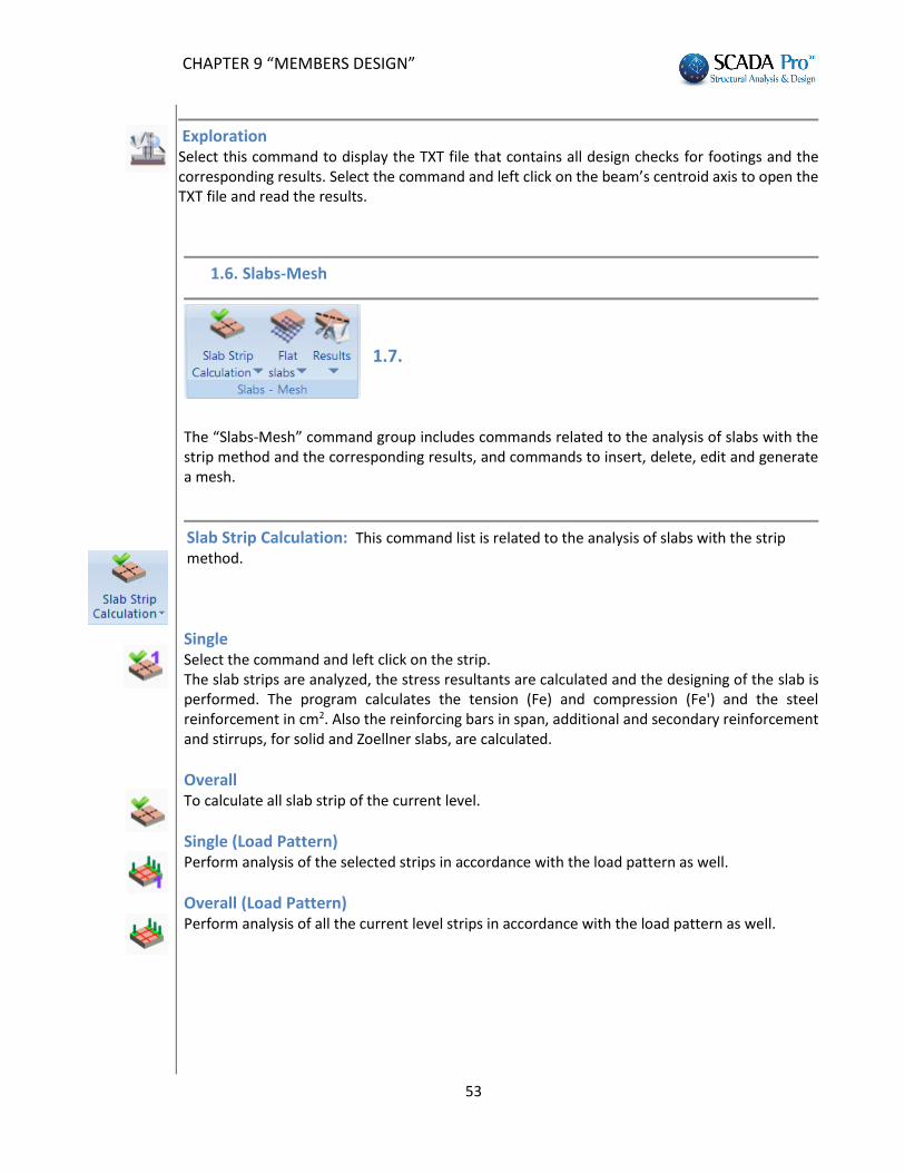
1.6. Slabs-Mesh
1.7.
The “Slabs-Mesh” command group includes commands related to the analysis of slabs with the strip method and the corresponding results, and commands to insert, delete, edit and generate a mesh.
Slab Strip Calculation: This command list is related to the analysis of slabs with the strip method.
Single Select the command and left click on the strip. The slab strips are analyzed, the stress resultants are calculated and the designing of the slab is performed. The program calculates the tension (Fe) and compression (Fe') and the steel reinforcement in cm2. Also the reinforcing bars in span, additional and secondary reinforcement and stirrups, for solid and Zoellner slabs, are calculated.
Overall To calculate all slab strip of the current level.
Single (Load Pattern) Perform analysis of the selected strips in accordance with the load pattern as well.
Overall (Load Pattern) Perform analysis of all the current level strips in accordance with the load pattern as well.
CHAPTER 9 “MEMBERS DESIGN”
54
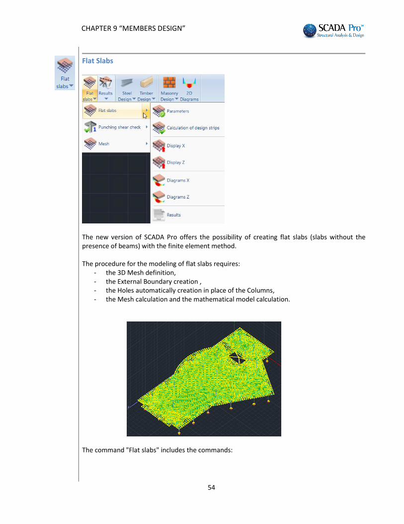
Flat Slabs
The new version of SCADA Pro offers the possibility of creating flat slabs (slabs without the presence of beams) with the finite element method. The procedure for the modeling of flat slabs requires:
- the 3D Mesh definition, - the External Boundary creation , - the Holes automatically creation in place of the Columns, - the Mesh calculation and the mathematical model calculation.
The command "Flat slabs" includes the commands:
CHAPTER 9 “MEMBERS DESIGN”
55
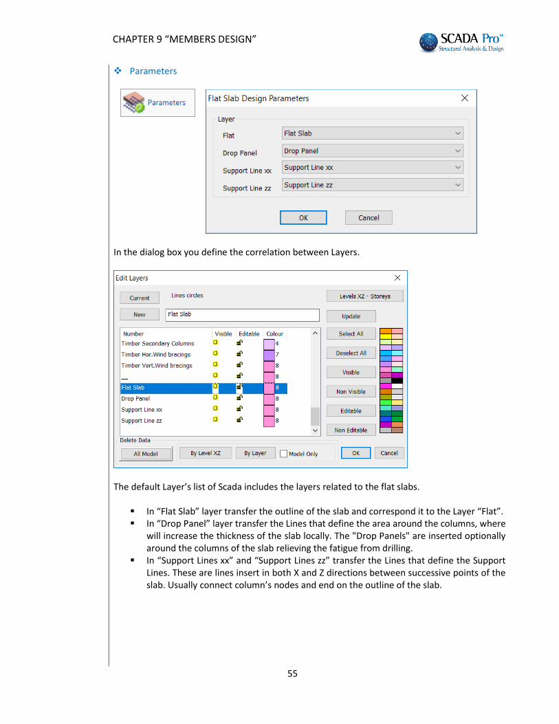
Parameters
In the dialog box you define the correlation between Layers.
The default Layer’s list of Scada includes the layers related to the flat slabs.
In “Flat Slab” layer transfer the outline of the slab and correspond it to the Layer “Flat”. In “Drop Panel” layer transfer the Lines that define the area around the columns, where
will increase the thickness of the slab locally. The "Drop Panels" are inserted optionally around the columns of the slab relieving the fatigue from drilling.
In “Support Lines xx” and “Support Lines zz” transfer the Lines that define the Support Lines. These are lines insert in both X and Z directions between successive points of the slab. Usually connect column’s nodes and end on the outline of the slab.
CHAPTER 9 “MEMBERS DESIGN”
56
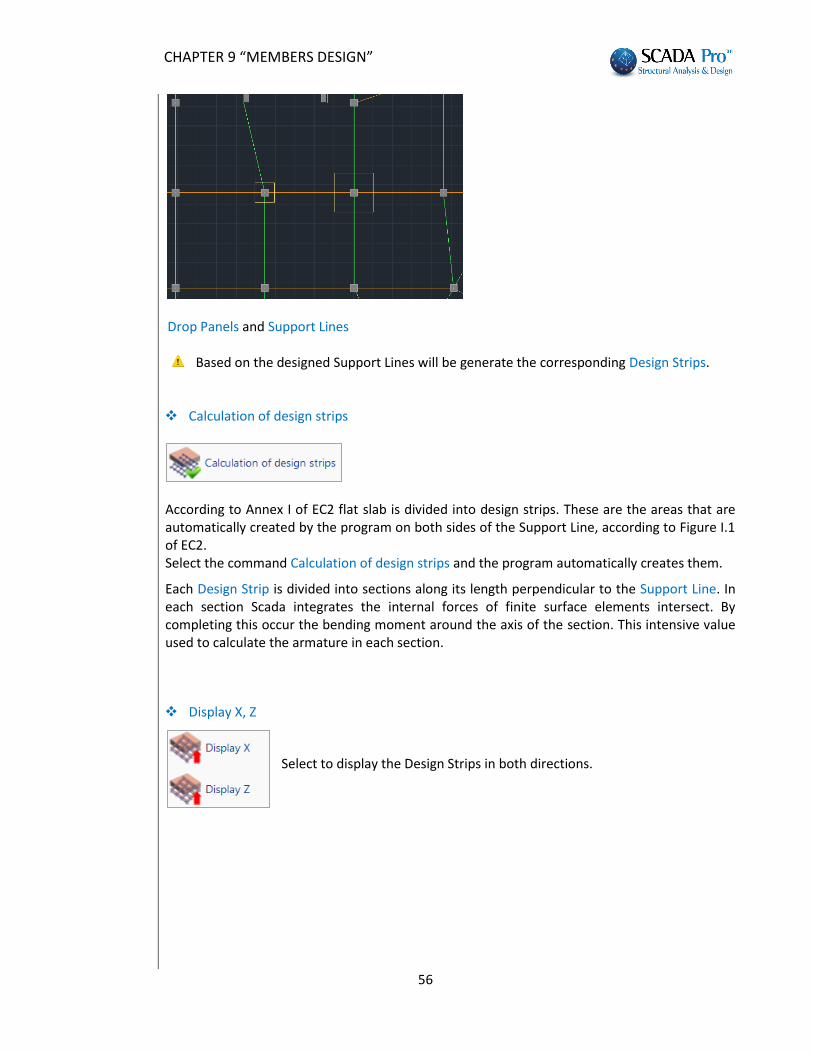
Drop Panels and Support Lines
Based on the designed Support Lines will be generate the corresponding Design Strips.
Calculation of design strips
According to Annex I of EC2 flat slab is divided into design strips. These are the areas that are automatically created by the program on both sides of the Support Line, according to Figure I.1 of EC2. Select the command Calculation of design strips and the program automatically creates them.
Each Design Strip is divided into sections along its length perpendicular to the Support Line. In each section Scada integrates the internal forces of finite surface elements intersect. By completing this occur the bending moment around the axis of the section. This intensive value used to calculate the armature in each section.
Display Χ, Ζ
Select to display the Design Strips in both directions.
CHAPTER 9 “MEMBERS DESIGN”
57
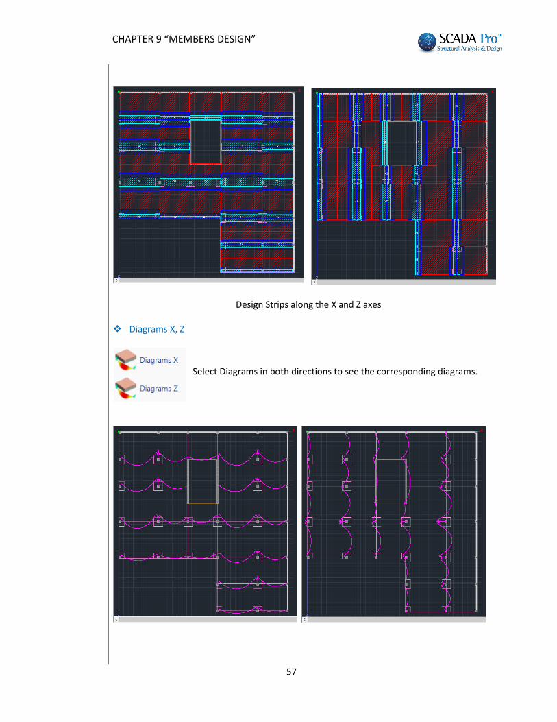
Design Strips along the X and Z axes
Diagrams Χ, Ζ
Select Diagrams in both directions to see the corresponding diagrams.
CHAPTER 9 “MEMBERS DESIGN”
58
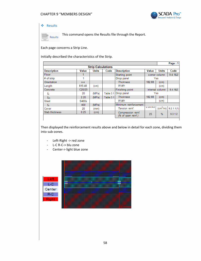
Results
This command opens the Results file through the Report.
Each page concerns a Strip Line. Initially described the characteristics of the Strip.
Then displayed the reinforcement results above and below in detail for each zone, dividing them into sub-zones.
- Left-Right -> red zone - L-C R-C-> blu zone - Center-> light blue zone
CHAPTER 9 “MEMBERS DESIGN”
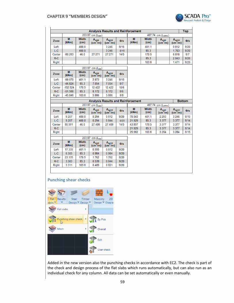
59
Punching shear checks
Added in the new version also the punching checks in accordance with EC2. The check is part of the check and design process of the flat slabs which runs automatically, but can also run as an individual check for any column. All data can be set automatically or even manually.
CHAPTER 9 “MEMBERS DESIGN”
60
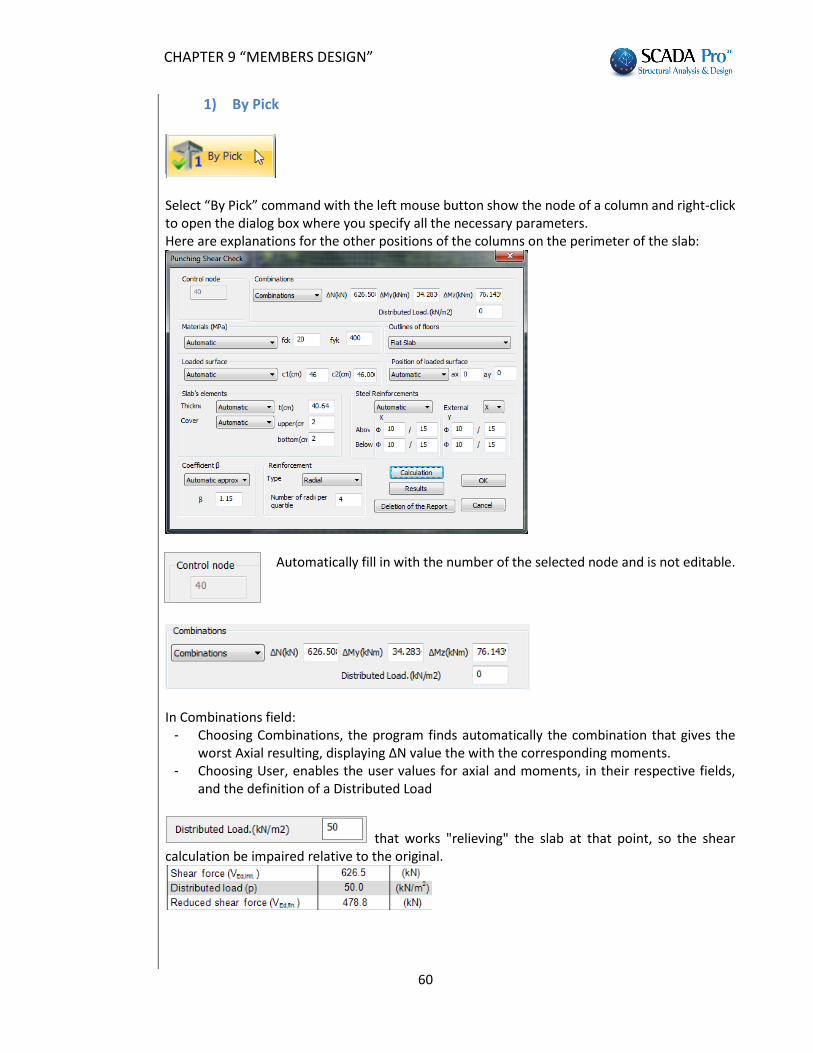
1) By Pick
Select “By Pick” command with the left mouse button show the node of a column and right-click to open the dialog box where you specify all the necessary parameters. Here are explanations for the other positions of the columns on the perimeter of the slab:
Automatically fill in with the number of the selected node and is not editable.
In Combinations field: - Choosing Combinations, the program finds automatically the combination that gives the
worst Axial resulting, displaying ΔΝ value the with the corresponding moments. - Choosing User, enables the user values for axial and moments, in their respective fields,
and the definition of a Distributed Load
that works "relieving" the slab at that point, so the shear calculation be impaired relative to the original.
CHAPTER 9 “MEMBERS DESIGN”
61
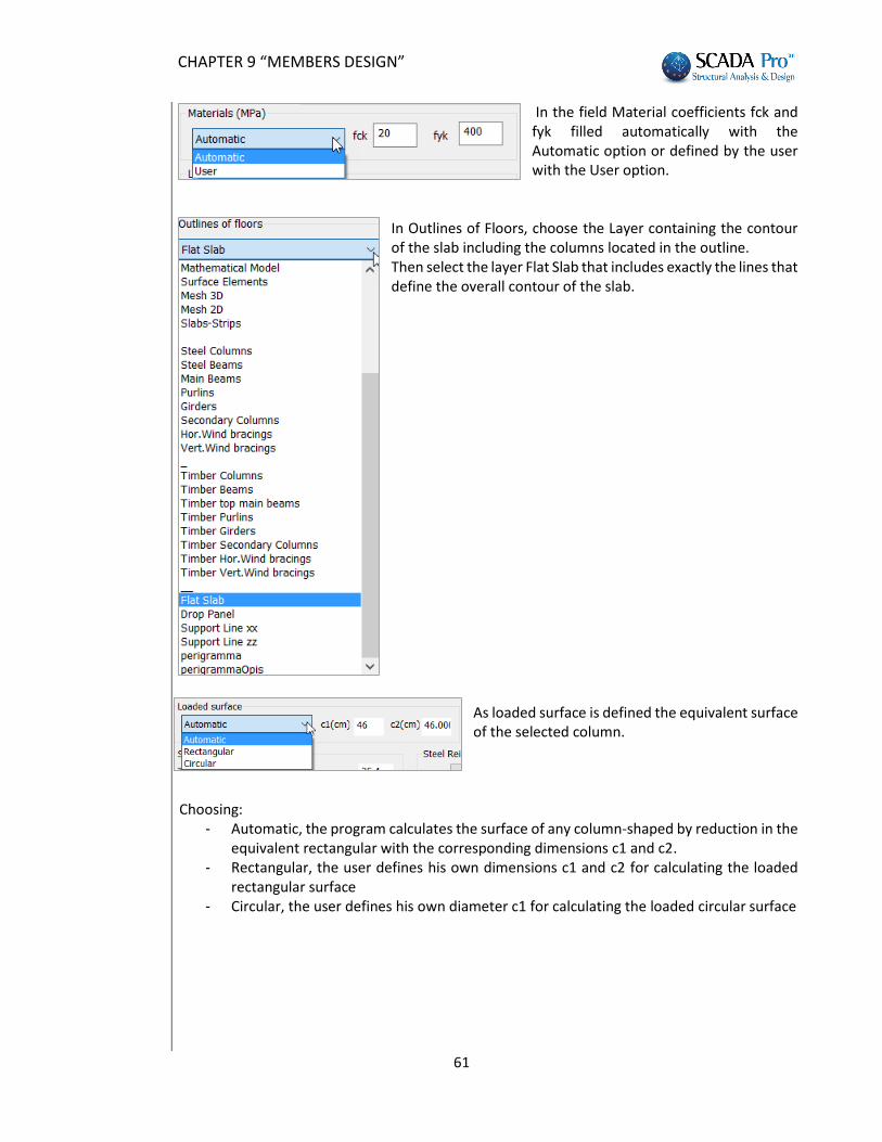
In the field Material coefficients fck and fyk filled automatically with the Automatic option or defined by the user with the User option.
In Outlines of Floors, choose the Layer containing the contour of the slab including the columns located in the outline. Then select the layer Flat Slab that includes exactly the lines that define the overall contour of the slab.
As loaded surface is defined the equivalent surface of the selected column.
Choosing:
- Automatic, the program calculates the surface of any column-shaped by reduction in the equivalent rectangular with the corresponding dimensions c1 and c2.
- Rectangular, the user defines his own dimensions c1 and c2 for calculating the loaded rectangular surface
- Circular, the user defines his own diameter c1 for calculating the loaded circular surface
CHAPTER 9 “MEMBERS DESIGN”
62
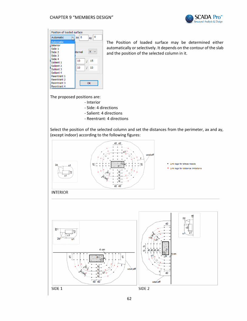
The Position of loaded surface may be determined either automatically or selectively. It depends on the contour of the slab and the position of the selected column in it.
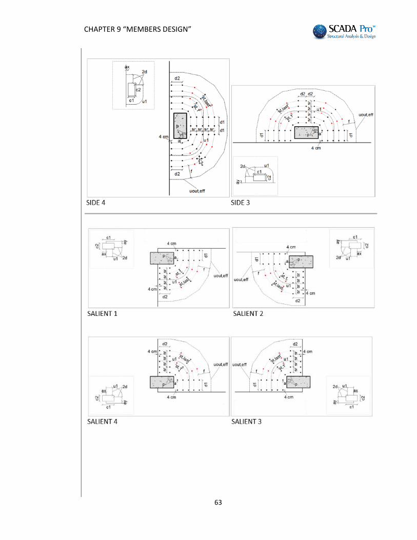
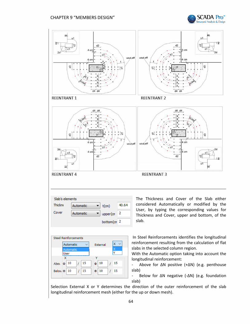
The proposed positions are: - Interior - Side: 4 directions - Salient: 4 directions - Reentrant: 4 directions Select the position of the selected column and set the distances from the perimeter, ax and ay, (except indoor) according to the following figures:
CHAPTER 9 “MEMBERS DESIGN”
63
CHAPTER 9 “MEMBERS DESIGN”
64
The Thickness and Cover of the Slab either considered Automatically or modified by the User, by typing the corresponding values for Thickness and Cover, upper and bottom, of the slab.
In Steel Reinforcements identifies the longitudinal reinforcement resulting from the calculation of flat slabs in the selected column region. With the Automatic option taking into account the longitudinal reinforcement: - Above for ΔΝ positive (+ΔΝ) (e.g. penthouse slab) - Below for ΔΝ negative (-ΔΝ) (e.g. foundation slab)
Selection External X or Y determines the direction of the outer reinforcement of the slab longitudinal reinforcement mesh (either for the up or down mesh).
CHAPTER 9 “MEMBERS DESIGN”
65
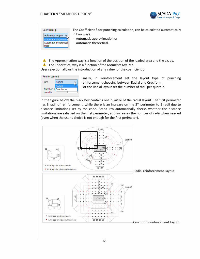
The Coefficient β for punching calculation, can be calculated automatically in two ways: - Automatic approximation or - Automatic theoretical.
The Approximation way is a function of the position of the loaded area and the ax, ay. The Theoretical way is a function of the Moments Μy, Mz.
User selection allows the introduction of any value for the coefficient β. Finally, in Reinforcement set the layout type of punching reinforcement choosing between Radial and Cruciform. For the Radial layout set the number of radii per quartile.
In the figure below the black box contains one quartile of the radial layout. The first perimeter has 3 radii of reinforcement, while there is an increase on the 3rd perimeter to 5 radii due to distance limitations set by the code. Scada Pro automatically checks whether the distance limitations are satisfied on the first perimeter, and increases the number of radii when needed (even when the user’s choice is not enough for the first perimeter).
CHAPTER 9 “MEMBERS DESIGN”
66
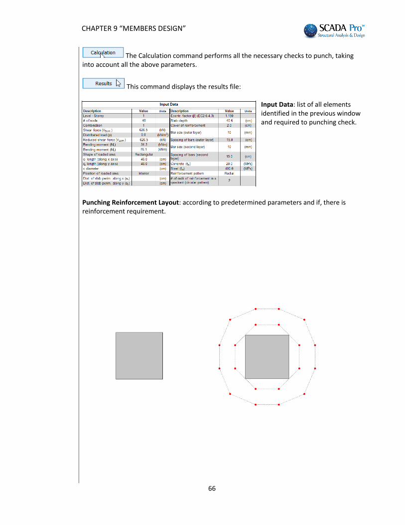
The Calculation command performs all the necessary checks to punch, taking into account all the above parameters.
This command displays the results file:
Input Data: list of all elements identified in the previous window and required to punching check.
Punching Reinforcement Layout: according to predetermined parameters and if, there is reinforcement requirement.
CHAPTER 9 “MEMBERS DESIGN”
67
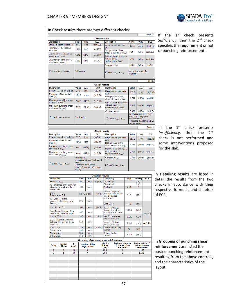
In Check results there are two different checks: If the 1st check presents Sufficiency, then the 2nd check specifies the requirement or not of punching reinforcement.
If the 1st check presents Insufficiency, then the 2nd check is not performed and some interventions proposed for the slab.
In Detailing results are listed in detail the results from the two checks in accordance with their respective formulas and chapters of EC2. In Grouping of punching shear reinforcement are listed the posted punching reinforcement resulting from the above controls, and the characteristics of the layout.
CHAPTER 9 “MEMBERS DESIGN”
68
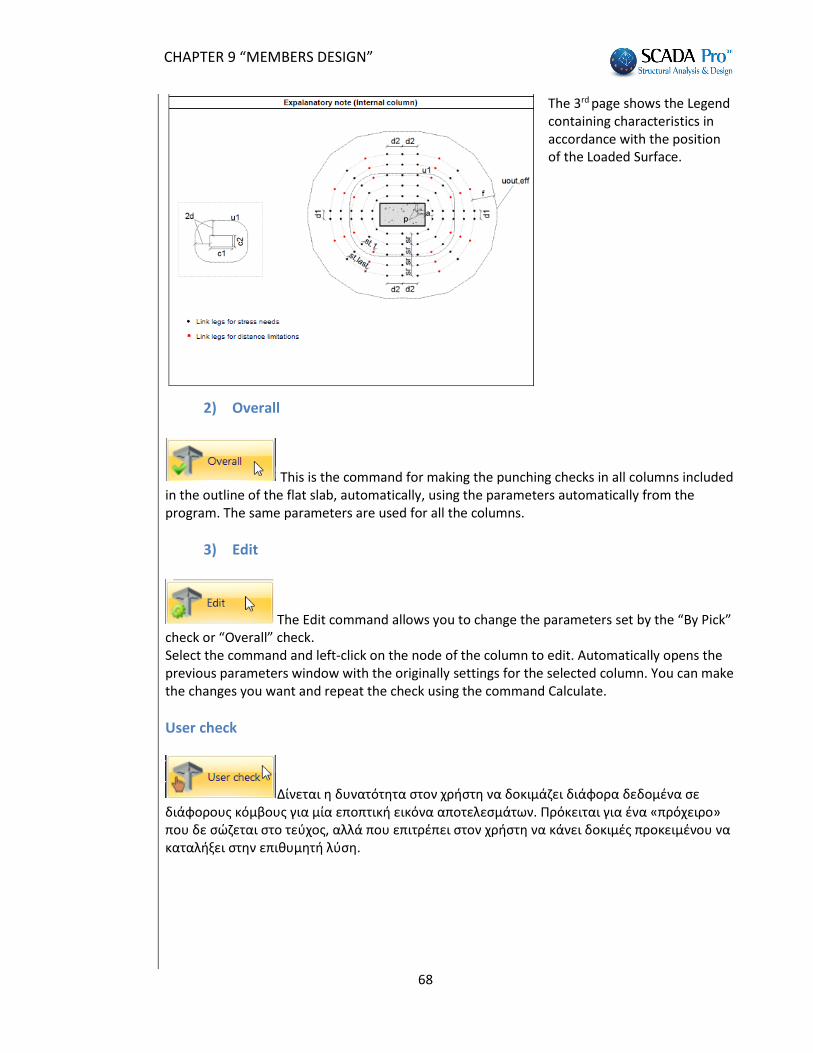
The 3rd page shows the Legend containing characteristics in accordance with the position of the Loaded Surface.
2) Overall
This is the command for making the punching checks in all columns included in the outline of the flat slab, automatically, using the parameters automatically from the program. The same parameters are used for all the columns.
3) Edit
The Edit command allows you to change the parameters set by the “By Pick” check or “Overall” check. Select the command and left-click on the node of the column to edit. Automatically opens the previous parameters window with the originally settings for the selected column. You can make the changes you want and repeat the check using the command Calculate.
User check
Δίνεται η δυνατότητα στον χρήστη να δοκιμάζει διάφορα δεδομένα σε διάφορους κόμβους για μία εποπτική εικόνα αποτελεσμάτων. Πρόκειται για ένα «πρόχειρο» που δε σώζεται στο τεύχος, αλλά που επιτρέπει στον χρήστη να κάνει δοκιμές προκειμένου να καταλήξει στην επιθυμητή λύση.
CHAPTER 9 “MEMBERS DESIGN”
69
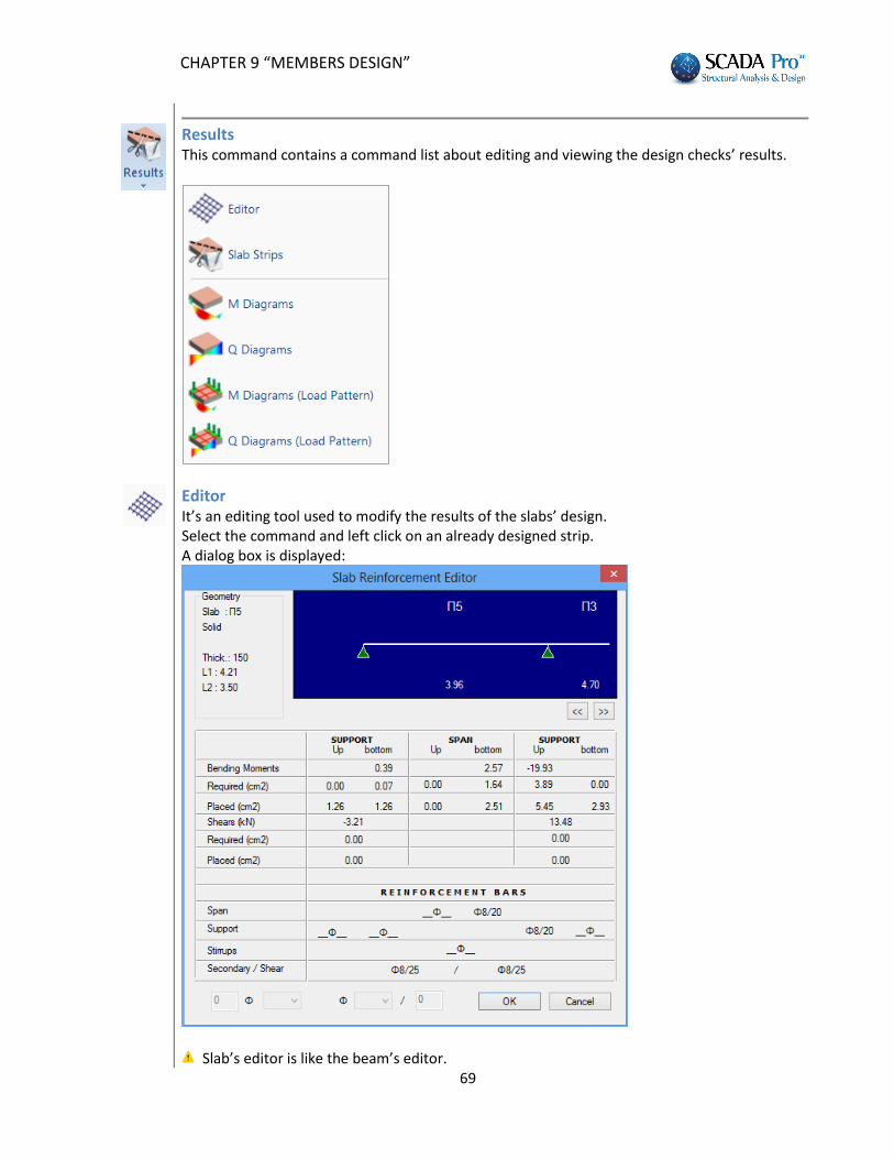
Results This command contains a command list about editing and viewing the design checks’ results.
Editor It’s an editing tool used to modify the results of the slabs’ design. Select the command and left click on an already designed strip. A dialog box is displayed:
Slab’s editor is like the beam’s editor.
CHAPTER 9 “MEMBERS DESIGN”
70
Slab Strips Select to display the TXT file that contains the design checks for slabs and the corresponding results. Select the command and left click on a strip to open the TXT file and read the results. The TXT files presented, are generated by the program for the printout.
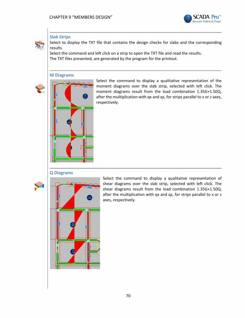
Μ Diagrams
Select the command to display a qualitative representation of the moment diagrams over the slab strip, selected with left click. The moment diagrams result from the load combination 1.35G+1.50Q, after the multiplication with qx and qz, for strips parallel to x or z axes, respectively.
Q Diagrams
Select the command to display a qualitative representation of shear diagrams over the slab strip, selected with left click. The shear diagrams result from the load combination 1.35G+1.50Q, after the multiplication with qx and qz, for strips parallel to x or z axes, respectively.

CHAPTER 9 “MEMBERS DESIGN”
71
Μ Diagrams (Load Pattern) Select the command to display a qualitative representation of the moment diagrams over the slab strip, selected with left click, resulting from a load pattern.
Q Diagrams (Load Pattern) Select the command to display a qualitative representation of shear diagrams over the slab strip, selected by left click, resulting from a load pattern.

CHAPTER 9 “MEMBERS DESIGN”
72


![A Program for MEM analysis from X-Ray and …...Chapter 1 INTRODUCTION The maximum entropy method (MEM) [1,2] is very useful to modify structural models adopted in Rietveld analysis](https://img.pdfslide.us/doc/110x75/5e83ef3fe960b6274a027c10/a-program-for-mem-analysis-from-x-ray-and-chapter-1-introduction-the-maximum.jpg)


![The ISP-SPIE Student chapter had an annual general body ... · { Mem # 03031326} Secretary : Mr. Jemy James[jemyjames@cusat.ac.in] {Mem # 03031208} Treasurer : Ms.Parvathi M.R.[parvathi82@cusat.ac.in]](https://img.pdfslide.us/doc/110x75/600c4d6b5f1b052248619f3a/the-isp-spie-student-chapter-had-an-annual-general-body-mem-03031326-secretary.jpg)