Embed Size (px)
Citation preview

Chapt. 9 – Sectional Strength CR092 17 January 2011
Page 3924
CHAPTER 9 — SECTIONAL STRENGTH 1
9.1 — Scope 2
9.1.1 — Provisions of this chapter shall govern the calculation of nominal strength at a section of 3 a member, unless the member or region of the member is designed in accordance with Chapter 4 17. <8.1.1> <8.1.2> <9.1.3> 5
9.1.2 — Design strength at a section shall be taken as the nominal strength multiplied by the 6 applicable strength reduction factor φ . <8.1.1> <9.1.1> <9.3.1> 7
9.1.3 — Nominal strength at a section of a member shall be calculated in accordance with: <~> 8
(a) 9.3 for flexure 9
(b) 9.4 for combined flexure and axial force 10
(c) 9.5 for one-way shear 11
(d) 9.6 for two-way shear 12
(e) 9.7 for torsion 13
9.2 — Design assumptions for flexural and axial strength 14
9.2.1 — Strain compatibility and equilibrium 15
9.2.1.1 — Strain compatibility and equilibrium shall be satisfied at each section. <10.2.1> 16 <10.3.1> <18.3.1> 17
9.2.1.2 — Strain in concrete and nonprestressed reinforcement shall be assumed proportional 18 to the distance from neutral axis. <10.2.2> 19
9.2.1.3 — Strain in bonded and unbonded prestressed reinforcement and concrete shall 20 include the strain due to effective prestress. <~> 21
9.2.1.4 — Changes in strain for bonded prestressed reinforcement shall be assumed 22 proportional to the distance from neutral axis. <18.3.2.1> 23
9.2.1.5 — Strain in unbonded prestressed reinforcement shall include cumulative effect of 24 strain along the unbonded length. <~> 25
26

Chapt. 9 – Sectional Strength CR092 17 January 2011
Page 3925
9.2.2 — Design assumptions for concrete 27
9.2.2.1 — Maximum strain at the extreme concrete compression fiber shall be assumed equal 28 to 0.003. <10.2.3> 29
9.2.2.2 — Shape of the concrete compressive stress distribution with respect to concrete 30 strain shall be assumed to be rectangular, trapezoidal, parabolic, or any other shape that 31 results in prediction of strength in substantial agreement with results of comprehensive tests. 32 <10.2.6> 33
9.2.2.3 — Tensile strength of concrete shall be neglected in flexural and axial strength 34 calculations. <10.2.5> <18.3.2.2> 35
9.2.2.4 — An equivalent rectangular concrete stress distribution, defined in 9.2.2.5 through 36 9.2.2.7, satisfies 9.2.2.2. <10.2.7> 37
9.2.2.5 — Concrete stress of 0.85fc′ shall be assumed uniformly distributed over an 38 equivalent compression zone bounded by edges of the cross section and a line parallel to the 39 neutral axis located a distance 1a cβ= from the fiber of maximum compressive strain. 40 <10.2.7.1> 41
9.2.2.6 — Distance from the fiber of maximum compressive strain to the neutral axis, c, shall 42 be measured perpendicular to the neutral axis. <10.2.7.2> 43
9.2.2.7 — Values of 1β shall be in accordance with Table 9.2.2.7 <10.2.7.3> 44
Table 9.2.2.7 — Values of 1β for equivalent rectangular concrete stress distribution 45
cf ′ , psi 1β
2500 cf ′≤ < 4000 0.85
4000 cf ′≤ < 8000 0.85 – 0.05( cf ′ – 4000)/1000
cf ′ ≥ 8000 0.65 46
9.2.3 — Design assumptions for nonprestressed reinforcement 47
References to 6.3.1, 6.3.2, and 6.3.4 per LB11-1. 48
9.2.3.1 — Deformed reinforcement conforming to Table 6.3.4(a) shall be permitted to resist 49 tensile or compressive forces in members. 50
9.2.3.2 — Stress-strain relationship and modulus of elasticity for deformed reinforcement 51 shall be permitted to be idealized in accordance with 6.3.1 and 6.3.2. <10.6.4> 52
9.2.3.3 — Deformed reinforcement conforming to Table 6.3.4(a) used with prestressed 53 reinforcement shall be permitted to be considered to contribute to the tensile force and be 54 included in flexural strength calculations at a stress equal to yf . <18.7.3> 55
56

Chapt. 9 – Sectional Strength CR092 17 January 2011
Page 3926
9.2.4 — Design assumptions for prestressing reinforcement 57
References to 6.4.1, 6.5.3, and 6.5.4 per LB11-1. 58
9.2.4.1 — For members with bonded prestressing reinforcement conforming to 6.4.1, stress 59 at nominal flexural strength, psf , shall be calculated in accordance with 6.5.4. <18.7.2> 60
9.2.4.2 — For members with unbonded prestressing reinforcement conforming to 6.4.1, psf 61
shall be calculated in accordance with 6.5.3. <18.7.2> 62
9.2.5 — Design assumptions for nonprestressed prestressing reinforcement 63
9.2.5.1 — Nonprestressed prestressing reinforcement shall be permitted to be included in 64 flexural strength calculations if a strain compatibility analysis is performed to determine 65 stresses in such reinforcement. <18.7.3> 66
Note: 18.7.3 in ACI 318-08 permits the use of “other nonprestressed reinforcement” that does 67 not conform to 3.5.3. This section now refers explicitly to nonprestressed prestressing 68 reinforcement. Sub E believes that a limit to the value of strand stress that may be used in design 69 and the minimum embedded length for nonprestressed strand should be should be added to 9.2.5 70 as NEW BUSINESS. 71
9.3 —Flexural strength 72
9.3.1 — General 73
9.3.1.1 — Calculation of nominal flexural strength nM shall be in accordance with the 74 assumptions of 9.2. <~> 75
9.3.2 — Strength reduction factor 76
9.3.2.1 — Strength reduction factor for flexural strength, fφ , in nonprestressed members 77
and at sections in pretensioned members where strand embedment equals or exceeds the 78 development length shall be calculated in accordance with Table 9.3.2.1, where tbε is the net 79 tensile strain in extreme tension steel corresponding to balanced strain conditions. <9.3.1> 80 <9.3.2.1> <10.3.2> <10.3.3> <10.3.4> <18.8.1> 81
Chapt. 9 – Sectional Strength CR092 17 January 2011
Page 3927
Table 9.3.2.1 — Strength reduction factor 82
Net tensile stain, tε Classification
fφ
Transverse reinforcement Spirals conforming
to 13.6.3 Other
t tb≤ε ε Compression controlled 0.75 0.65
0.005tb t< <ε ε Transition ( )
( )0.75 0.15
0.005t tb
tb
−+
−ε ε
ε ( )
( )0.65 0.25
0.005t tb
tb
−+
−ε ε
ε
t ≥ε 0.005 Tension controlled 0.90 0.90
83 Add to Chapter 2: 84
tbε = net tensile strain in extreme tension steel corresponding to balanced strain conditions. 85 86
fφ = strength reduction factor for flexural and axial strength 87
88 vφ = strength reduction factor for shear and torsional strength 89
90 balanced strain conditions – strain distribution in cross section at which strain in the extreme concrete 91 compression fiber is 0.003 and strain at centroid of tension reinforcement is equal to yield strain. 92
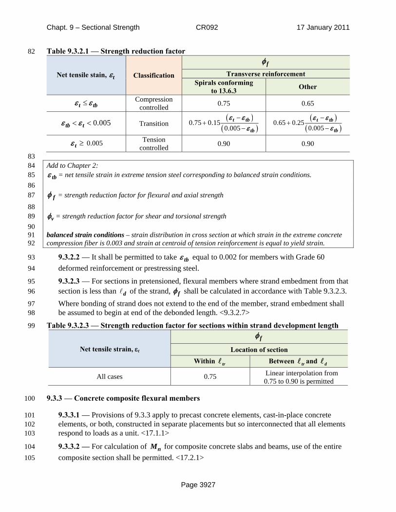
9.3.2.2 — It shall be permitted to take tbε equal to 0.002 for members with Grade 60 93 deformed reinforcement or prestressing steel. 94
9.3.2.3 — For sections in pretensioned, flexural members where strand embedment from that 95 section is less than d of the strand, fφ shall be calculated in accordance with Table 9.3.2.3. 96
Where bonding of strand does not extend to the end of the member, strand embedment shall 97 be assumed to begin at end of the debonded length. <9.3.2.7> 98
Table 9.3.2.3 — Strength reduction factor for sections within strand development length 99
Net tensile strain, εt fφ
Location of section Within Between and
All cases 0.75 Linear interpolation from 0.75 to 0.90 is permitted
9.3.3 — Concrete composite flexural members 100
9.3.3.1 — Provisions of 9.3.3 apply to precast concrete elements, cast-in-place concrete 101 elements, or both, constructed in separate placements but so interconnected that all elements 102 respond to loads as a unit. <17.1.1> 103
9.3.3.2 — For calculation of nM for composite concrete slabs and beams, use of the entire 104 composite section shall be permitted. <17.2.1> 105
tr tr d

Chapt. 9 – Sectional Strength CR092 17 January 2011
Page 3928
9.3.3.3 — For calculation of nM for composite concrete slabs and beams, no distinction 106 shall be made between shored and unshored members. <17.2.4> 107
9.3.3.4 — For calculation of nM for composite concrete slabs and beams where the 108 specified concrete compressive strength, unit weight, or other properties of different elements 109 vary, properties of the individual elements or the critical values shall be used in design. 110 <17.2.3> 111
9.4 — Combined flexural and axial strength 112
9.4.1 — General 113
9.4.1.1 — Nominal strength calculations for combined flexure and axial force shall be in 114 accordance with the assumptions of 9.2. <18.11.1> 115
9.4.2 — Strength reduction factors 116
9.4.2.1 — Strength reduction factor for combined flexural and axial strength, fφ , shall be in 117
accordance with Table 9.3.2.1. <9.3.1> <10.3.2> <10.3.3> <10.3.4> <18.8.1> 118
9.4.3 — Maximum axial strength 119
9.4.3.1 — Nominal axial strength of column, nP , shall not be taken greater than ,maxnP , as 120
defined in Table 9.4.3.1. <10.3.6> <10.3.6.1> <10.3.6.2> <10.3.6.3> 121
122 Table 9.4.3.1— Maximum axial strength 123
Column Transverse Reinforcement ,maxnP
Nonprestressed
Ties ( )0.80 0.85 c g st y stf A A f A⎡ ⎤′ − +⎣ ⎦ (a)
Spirals conforming to
12.6.3.1 ( )0.85 0.85 c g st y stf A A f A⎡ ⎤′ − +⎣ ⎦ (b)
Prestressed
Ties ( ) ( )0.80 0.85 0.003c g st pc y st se p pcf A A A f A f E A⎡ ⎤′ − − + − −⎣ ⎦ (c)
Spirals conforming to
12.6.3.1 ( ) ( )0.85 0.85 0.003c g st pc y st se p pcf A A A f A f E A⎡ ⎤′ − − + − −⎣ ⎦ (d)
Composite conforming to
10.13 All ( )0.85 0.85 c g st y stf A A f A⎡ ⎤′ − +⎣ ⎦ (e)
124 Add to Chapter 2: 125
pcA = total area of prestressed longitudinal reinforcement, in.2 126
127
Chapt. 9 – Sectional Strength CR092 17 January 2011
Page 3929
Reference to 12.6.3.1 corresponds to Version 1.0. Reference to 10.13 corresponds to 318-08. 128 Reorganized chapter on columns has not yet been balloted by 318. 129
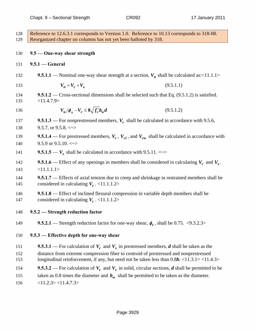
9.5 — One-way shear strength 130
9.5.1 — General 131
9.5.1.1 — Nominal one-way shear strength at a section, nV shall be calculated as:<11.1.1> 132
n c sV V V= + (9.5.1.1) 133
9.5.1.2 — Cross-sectional dimensions shall be selected such that Eq. (9.5.1.2) is satisfied. 134 <11.4.7.9> 135
′− ≤ 8u c c wvV V f b dφ (9.5.1.2) 136
9.5.1.3 — For nonprestressed members, cV shall be calculated in accordance with 9.5.6, 137 9.5.7, or 9.5.8. <~> 138
9.5.1.4 — For prestressed members, cV , ciV , and cwV shall be calculated in accordance with 139 9.5.9 or 9.5.10. <~> 140
9.5.1.5 — sV shall be calculated in accordance with 9.5.11. <~> 141
9.5.1.6 — Effect of any openings in members shall be considered in calculating cV and sV . 142 <11.1.1.1> 143
9.5.1.7 — Effects of axial tension due to creep and shrinkage in restrained members shall be 144 considered in calculating cV . <11.1.1.2> 145
9.5.1.8 — Effect of inclined flexural compression in variable depth members shall be 146 considered in calculating cV . <11.1.1.2> 147
9.5.2 — Strength reduction factor 148
9.5.2.1 — Strength reduction factor for one-way shear, vφ , shall be 0.75. <9.3.2.3> 149
9.5.3 — Effective depth for one-way shear 150
9.5.3.1 — For calculation of cV and sV in prestressed members, d shall be taken as the 151 distance from extreme compression fiber to centroid of prestressed and nonprestressed 152 longitudinal reinforcement, if any, but need not be taken less than 0.8h. <11.3.1> <11.4.3> 153
9.5.3.2 — For calculation of cV and sV in solid, circular sections, d shall be permitted to be 154 taken as 0.8 times the diameter and wb shall be permitted to be taken as the diameter. 155 <11.2.3> <11.4.7.3> 156

Chapt. 9 – Sectional Strength CR092 17 January 2011
Page 3930
9.5.4 — Limiting material strengths for one-way shear 157
9.5.4.1 — For one-way shear, the value of used to calculate cV , ciV , and cwV shall not 158
exceed 100 psi. <11.1.2> <11.1.2.1> 159
9.5.4.2 — Values of yf and ytf used to calculate sV shall be in accordance with Table 160
6.3.4(a). <11.4.2> 161
Reference to 6.4.3 per LB11-1. 162
9.5.5 — Composite concrete members 163
9.5.5.1 — For calculation of nV for composite concrete members, no distinction shall be 164 made between shored and unshored members. <17.2.4> 165
9.5.5.2 — For calculation of cV for composite concrete members where the specified 166 concrete compressive strength, unit weight, or other properties of different elements vary, 167 properties of the individual elements or the critical values shall be used in design. <17.2.3> 168
9.5.5.3 — If an entire composite concrete member is assumed to resist vertical shear, cV 169 shall be permitted to be calculated assuming a monolithically cast member of the same cross-170 sectional shape. <17.2.1> <17.4.1> 171
9.5.5.4 — If an entire composite concrete member is assumed to resist vertical shear, sV 172 shall be permitted to be calculated assuming a monolithically cast member of the same cross-173 sectional shape if shear reinforcement is fully anchored into the interconnected elements in 174 accordance with 20.8. <17.4.1> <17.4.2> 175
Reference to 20.8 per LB10-3. 176
9.5.6 — cV for nonprestressed members without axial force 177
9.5.6.1 — cV shall be permitted to be calculated using the simplified or detailed options in 178 Table 9.5.6.1. <11.2.1.1> <11.2.2> <11.2.2.1> 179
Table 9.5.6.1— cV for nonprestressed members without axial force 180
Calculation options cV
Simplified 2 c wf b d'λ (a)
Detailed Least of:
1 9 2500 uc w w
u
V df b d
Mρ
⎛ ⎞+⎜ ⎟
⎝ ⎠'. λ (b)*
( )1 9 2500c w wf b dρ+'. λ (c)
3 5 c wf b d'. λ (d)
* uM and uV occur simultaneously at section considered.
cf'

Chapt. 9 – Sectional Strength CR092 17 January 2011
Page 3931
9.5.7 — cV for nonprestressed members with axial compression 181
9.5.7.1 — cV shall be permitted to be calculated using the simplified or detailed options in 182 Table 9.5.7.1, where uN is positive for compression. <11.2.1.1> <11.2.2> <11.2.2.1> 183
Table 9.5.7.1 — cV for nonprestressed members with axial compression 184
Calculation options cV
Simplified 2 12000
uc w
g
Nf b d
A
⎛ ⎞+⎜ ⎟⎜ ⎟
⎝ ⎠
'λ (a)
Detailed Lesser of:
( )1 9 25004
8
uc w w
u u
V df b d
h dM N
ρ'.
⎛ ⎞⎜ ⎟⎜ ⎟λ +
−⎜ ⎟−⎜ ⎟⎝ ⎠
(b)*
3 5 1500
uc w
g
Nf b d
A'. λ + (c)
* Not applicable if ( )4
08u u
h dM N
−− ≤ . uM , uN , and uV occur simultaneously at section
considered.
9.5.8 — cV for nonprestressed members with axial tension 185
9.5.8.1 — cV shall be permitted to be calculated using the simplified or detailed options in 186 Table 9.5.8.1, where uN is negative for tension. <11.2.1.1> <11.2.2> <11.2.2.1> 187
Table 9.5.8.1 — cV for nonprestressed members with axial tension 188
Calculation options cV
Simplified 0.0 (a)
Detailed Greater of: 2 1
500u
c wg
Nf b d
Aλ
⎛ ⎞′+⎜ ⎟⎜ ⎟
⎝ ⎠ (b)
0.0 (c)
9.5.9 — cV for pretensioned members beyond transfer length and post-tensioned members 189
9.5.9.1 — For prestressed flexural members with effective prestress force not less than 40 190 percent of the tensile strength of the flexural reinforcement, cV shall be permitted to be 191 calculated in accordance with Table 9.5.9.1. <11.3.2> 192
193

Chapt. 9 – Sectional Strength CR092 17 January 2011
Page 3932
Table 9.5.9.1— cV for prestressed members 194
cV
Greater of:
2 c wf b dλ ′ (a)
Least of:
0 6 700 u pc w
u
V df b d
Mλ.
⎛ ⎞′ +⎜ ⎟
⎝ ⎠ (b)*
( )0 6 700c wf b dλ. ′ + (c)
5 c wf b dλ ′ (d)
* Actual value of pd shall be used in row (b). uM and uV occur simultaneously at the
section considered.
9.5.9.2 — For prestressed members, cV shall also be permitted to be taken as the lesser of 195
ciV and cwV calculated in accordance with Table 9.5.9.2 and creM shall be calculated as: 196 <11.3.3> < 11.3.3.1> <11.3.3.2> 197
( )6cre c pe dt
IM f f fy
λ⎛ ⎞
′= + −⎜ ⎟⎝ ⎠
(9.5.9.2) 198
Table 9.5.9.2 — Alternate method for calculating cV for prestressed members 199
Types of shear cracking investigated cV
ciV
Greater of: 0 6 i cre
c w p dmax
V Mf b d V
M'. λ + +
(a)*,†
1 7 c wf b d'. λ (b)
cwV
( )3 5 0 3c pc w p pf f b d V. ' .λ + +
(c)†
* Mmax and iV correspond to the load combination causing maximum factored moment at the section.
† pd need not be taken less than 0.8h in Rows (a) and (c).
9.5.9.3 — Alternatively, cwV shall be permitted to be calculated as the shear force 200 corresponding to dead load, D, plus live load, L, that results in a principal tensile stress of 201 4 cf ′λ at the centroidal axis of member, or at the intersection of flange and web when the 202
centroidal axis is in the flange. <11.3.3.2> 203
9.5.9.4 — In composite members, the composite cross section shall be used in calculating the 204 principal tensile stress defined in 9.5.9.3 due to post-composite loads. <11.3.3.2> 205
Chapt. 9 – Sectional Strength CR092 17 January 2011
Page 3933
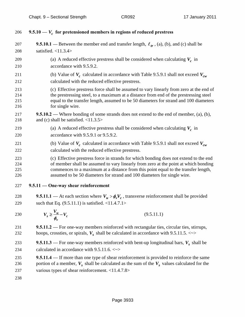
9.5.10 — cV for pretensioned members in regions of reduced prestress 206
9.5.10.1 — Between the member end and transfer length, tr , (a), (b), and (c) shall be 207 satisfied. <11.3.4> 208
(a) A reduced effective prestress shall be considered when calculating cV in 209 accordance with 9.5.9.2. 210
(b) Value of cV calculated in accordance with Table 9.5.9.1 shall not exceed cwV 211 calculated with the reduced effective prestress. 212
(c) Effective prestress force shall be assumed to vary linearly from zero at the end of 213 the prestressing steel, to a maximum at a distance from end of the prestressing steel 214 equal to the transfer length, assumed to be 50 diameters for strand and 100 diameters 215 for single wire. 216
9.5.10.2 — Where bonding of some strands does not extend to the end of member, (a), (b), 217 and (c) shall be satisfied. <11.3.5> 218
(a) A reduced effective prestress shall be considered when calculating cV in 219 accordance with 9.5.9.1 or 9.5.9.2. 220
(b) Value of cV calculated in accordance with Table 9.5.9.1 shall not exceed cwV 221 calculated with the reduced effective prestress. 222
(c) Effective prestress force in strands for which bonding does not extend to the end 223 of member shall be assumed to vary linearly from zero at the point at which bonding 224 commences to a maximum at a distance from this point equal to the transfer length, 225 assumed to be 50 diameters for strand and 100 diameters for single wire. 226
9.5.11 — One-way shear reinforcement 227
9.5.11.1 — At each section where >u v cV Vφ , transverse reinforcement shall be provided 228 such that Eq. (9.5.11.1) is satisfied. <11.4.7.1> 229
us c
v
VV V
φ≥ − (9.5.11.1) 230
9.5.11.2 — For one-way members reinforced with rectangular ties, circular ties, stirrups, 231 hoops, crossties, or spirals, sV shall be calculated in accordance with 9.5.11.5. <~> 232
9.5.11.3 — For one-way members reinforced with bent-up longitudinal bars, sV shall be 233 calculated in accordance with 9.5.11.6. <~> 234
9.5.11.4 — If more than one type of shear reinforcement is provided to reinforce the same 235 portion of a member, sV shall be calculated as the sum of the sV values calculated for the 236 various types of shear reinforcement. <11.4.7.8> 237
238
Chapt. 9 – Sectional Strength CR092 17 January 2011
Page 3934
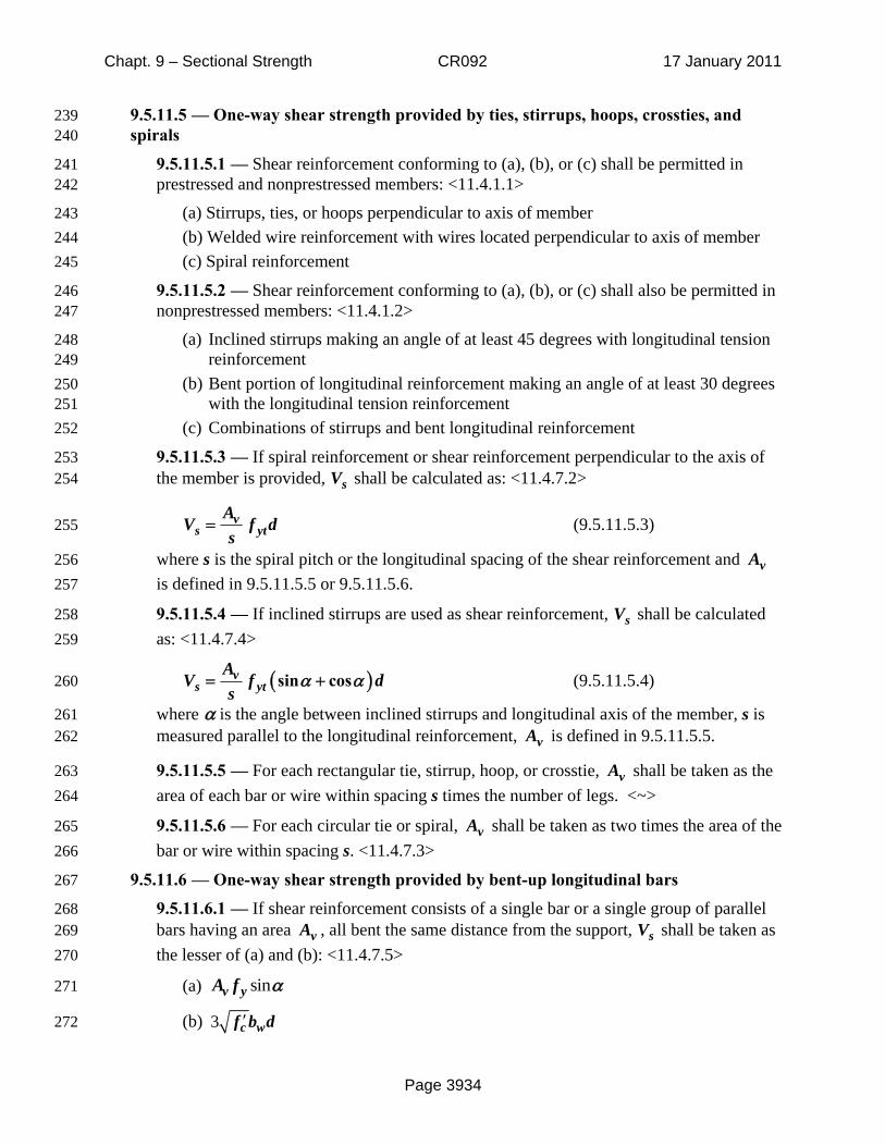
9.5.11.5 — One-way shear strength provided by ties, stirrups, hoops, crossties, and 239 spirals 240
9.5.11.5.1 — Shear reinforcement conforming to (a), (b), or (c) shall be permitted in 241 prestressed and nonprestressed members: <11.4.1.1> 242
(a) Stirrups, ties, or hoops perpendicular to axis of member 243 (b) Welded wire reinforcement with wires located perpendicular to axis of member 244 (c) Spiral reinforcement 245
9.5.11.5.2 — Shear reinforcement conforming to (a), (b), or (c) shall also be permitted in 246 nonprestressed members: <11.4.1.2> 247
(a) Inclined stirrups making an angle of at least 45 degrees with longitudinal tension 248 reinforcement 249
(b) Bent portion of longitudinal reinforcement making an angle of at least 30 degrees 250 with the longitudinal tension reinforcement 251
(c) Combinations of stirrups and bent longitudinal reinforcement 252
9.5.11.5.3 — If spiral reinforcement or shear reinforcement perpendicular to the axis of 253 the member is provided, sV shall be calculated as: <11.4.7.2> 254
vs yt
AV f d
s= (9.5.11.5.3) 255
where s is the spiral pitch or the longitudinal spacing of the shear reinforcement and vA 256 is defined in 9.5.11.5.5 or 9.5.11.5.6. 257
9.5.11.5.4 — If inclined stirrups are used as shear reinforcement, sV shall be calculated 258 as: <11.4.7.4> 259
( )vs yt
AV f d
sα αsin cos= + (9.5.11.5.4) 260
where α is the angle between inclined stirrups and longitudinal axis of the member, s is 261 measured parallel to the longitudinal reinforcement, vA is defined in 9.5.11.5.5. 262
9.5.11.5.5 — For each rectangular tie, stirrup, hoop, or crosstie, vA shall be taken as the 263 area of each bar or wire within spacing s times the number of legs. <~> 264
9.5.11.5.6 — For each circular tie or spiral, vA shall be taken as two times the area of the 265 bar or wire within spacing s. <11.4.7.3> 266
9.5.11.6 — One-way shear strength provided by bent-up longitudinal bars 267
9.5.11.6.1 — If shear reinforcement consists of a single bar or a single group of parallel 268 bars having an area vA , all bent the same distance from the support, sV shall be taken as 269 the lesser of (a) and (b): <11.4.7.5> 270
(a) sinv yA f α 271
(b) 3 c wf b d′ 272
Chapt. 9 – Sectional Strength CR092 17 January 2011
Page 3935
where α is the angle between bent-up reinforcement and longitudinal axis of the 273 member. 274
9.5.11.6.2 — Only the center three-fourths of the inclined portion of any longitudinal 275 bent bar shall be considered effective for shear reinforcement. <11.4.7.7> 276
9.5.11.6.3 — If shear reinforcement consists of a series of parallel bent-up bars or groups 277 of parallel bent-up bars at different distances from the support, sV shall be calculated in 278 accordance with Eq. (9.5.11.5.4). <11.4.7.6> 279
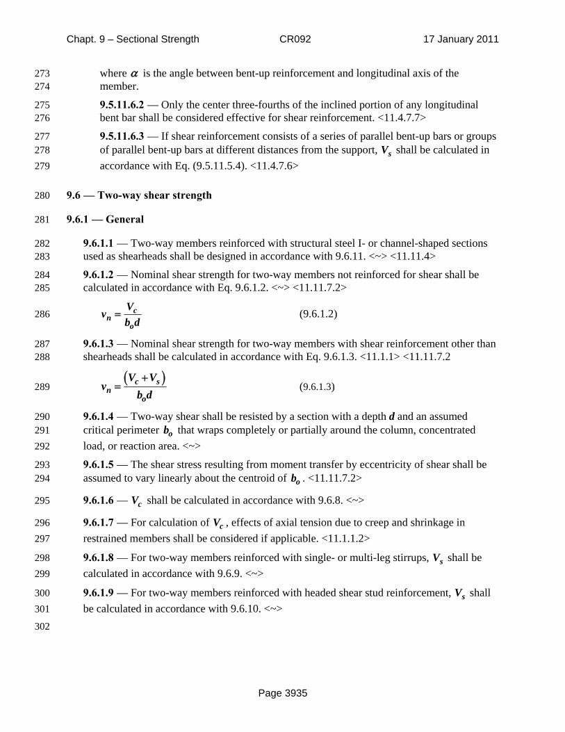
9.6 — Two-way shear strength 280
9.6.1 — General 281
9.6.1.1 — Two-way members reinforced with structural steel I- or channel-shaped sections 282 used as shearheads shall be designed in accordance with 9.6.11. <~> <11.11.4> 283
9.6.1.2 — Nominal shear strength for two-way members not reinforced for shear shall be 284 calculated in accordance with Eq. 9.6.1.2. <~> <11.11.7.2> 285
cn
o
Vv
b d= (9.6.1.2) 286
9.6.1.3 — Nominal shear strength for two-way members with shear reinforcement other than 287 shearheads shall be calculated in accordance with Eq. 9.6.1.3. <11.1.1> <11.11.7.2 288
( )c sn
o
V Vv
b d+
= (9.6.1.3) 289
9.6.1.4 — Two-way shear shall be resisted by a section with a depth d and an assumed 290 critical perimeter ob that wraps completely or partially around the column, concentrated 291 load, or reaction area. <~> 292
9.6.1.5 — The shear stress resulting from moment transfer by eccentricity of shear shall be 293 assumed to vary linearly about the centroid of ob . <11.11.7.2> 294
9.6.1.6 — cV shall be calculated in accordance with 9.6.8. <~> 295
9.6.1.7 — For calculation of cV , effects of axial tension due to creep and shrinkage in 296 restrained members shall be considered if applicable. <11.1.1.2> 297
9.6.1.8 — For two-way members reinforced with single- or multi-leg stirrups, sV shall be 298 calculated in accordance with 9.6.9. <~> 299
9.6.1.9 — For two-way members reinforced with headed shear stud reinforcement, sV shall 300 be calculated in accordance with 9.6.10. <~> 301
302

Chapt. 9 – Sectional Strength CR092 17 January 2011
Page 3936
9.6.2 — Strength reduction factor 303
9.6.2.1 — Strength reduction factor for two-way shear, vφ , shall be 0.75. <9.3.2.3> 304
9.6.3 — Effective depth for two-way shear 305
9.6.3.1 — For calculation of cV and sV in two-way, prestressed members, d shall be taken as 306 the distance from extreme compression fiber to centroid of prestressed and nonprestressed 307 longitudinal reinforcement, if any, but need not be taken less than 0.8h. <11.3.1> <11.4.3> 308
9.6.4 — Limiting material strengths for two-way shear 309
9.6.4.1 — For two-way shear, the value of used to calculate cV shall not exceed 100 psi. 310
<11.1.2> <11.1.2.1> 311
9.6.4.2 — Value of ytf used to calculate sV shall be in accordance with Table 6.3.4(a). 312
<11.4.2> 313
Reference to 6.3.4 per LB11-1. 314
9.6.5 — Inner critical sections for two-way members 315
9.6.5.1 — For two-way shear, each of the critical sections to be considered shall be located 316 so that its perimeter ob is a minimum but need not be closer than d/2 to: <11.11.1.2> 317 <15.5.2> 318
(a) Edges or corners of columns, concentrated loads, or reaction areas 319 (b) Changes in slab or footing thickness, such as edges of shear capitals and drop panels 320
9.6.5.2 — For square or rectangular columns, concentrated loads, or reaction areas, critical 321 section for two-way shear shall be permitted to be calculated assuming straight sides. 322 <11.11.1.3> 323
9.6.5.3 — For a circular or regular polygon-shaped column, critical section for two-way 324 shear shall be permitted to be calculated assuming a square column of equivalent area. 325 <15.3> 326
9.6.5.4 — If an opening is located within a column strip or closer than 10h from a 327 concentrated load or reaction area, a portion of ob enclosed by straight lines projecting from 328 the centroid of the column, concentrated load or reaction area and tangent to the boundaries 329 of the opening shall be considered ineffective. <11.11.6> 330
cf'

Chapt. 9 – Sectional Strength CR092 17 January 2011
Page 3937
9.6.6 — Outer critical section for two-way members with shear reinforcement 331
9.6.6.1 — For two-way members reinforced with single- or multi-leg stirrups, a critical 332 section located d/2 outside the outermost line of stirrup legs that surround the column shall 333 be considered. <11.11.7.2> 334
9.6.6.2 — For two-way members reinforced with headed shear stud reinforcement, a critical 335 section located d/2 outside the outermost peripheral line of shear reinforcement shall be 336 considered. <11.11.5.4> 337
9.6.7 — Maximum shear for two-way members with shear reinforcement 338
9.6.7.1 — For two-way members with shear reinforcement, value of cV calculated at inner 339 critical sections defined in 9.6.5 shall not exceed the values given in Table 9.6.7.1. 340 <11.11.7.2> 341
Table 9.6.7.1 — Maximum cV at inner critical sections for two-way members with shear 342 reinforcement 343
Type of shear reinforcement Maximum cV
Stirrups 2 c of b dλ ′
Headed shear stud reinforcement 3 c of b dλ ′
9.6.7.2 — For two-way members with shear reinforcement, values of nv at inner critical 344 sections defined in 9.6.5 and outer critical sections defined in 9.6.6 shall not exceed the 345 values given in Table 9.6.7.2. <11.11.5.4> <11.11.7.2> <11.11.7.3> 346
Table 9.6.7.2— Maximum nv for two-way members with shear reinforcement 347
Type of shear reinforcement
Maximum nv at inner critical sections
Maximum nv at outer critical section
Stirrups 6 cf ′ 2 cfλ ′
Headed shear stud reinforcement 8 cf ′ 2 cfλ ′

Chapt. 9 – Sectional Strength CR092 17 January 2011
Page 3938
9.6.8 — Two-way shear strength provided by concrete 348
9.6.8.1 — For two-way shear, cV shall be the least of (a), (b), and (c): 349
(a) 4 c of b dλ ′ 350
(b) 42 c of b dλβ
⎛ ⎞ ′+⎜ ⎟⎝ ⎠
351
(c) 2 sc o
o
df b d
bα
λ⎛ ⎞
′+⎜ ⎟⎝ ⎠
352
where β is the ratio of long side to short side of the column, concentrated load, or reaction 353 area and sα is defined in 9.6.8.4. <11.11.2.1> 354
9.6.8.2 — For prestressed, two-way members satisfying (a), (b), and (c), it shall be permitted 355 to calculate cV using 9.6.8.3. <11.11.2.2> 356
(a) Bonded reinforcement is provided in accordance with 12.6.3.4 and 12.7.2.4 357 (b) No portion of the column cross section is closer to a discontinuous edge than four times the 358
slab thickness h 359
(c) Effective prestress, pcf , in each direction is not less than 125 psi 360
Reference to 12.6.3.4 and 12.7.2.4 per LB11-1. 361
9.6.8.3 — For prestressed, two-way members conforming to 9.6.8.2, cV shall be permitted to 362 be calculated as the lesser of (a) and (b): <11.11.2.2> 363
(a) ( )3.5 0.3c pc o pf f b d Vλ ′ + + 364
(b) 1.5 0.3sc pc o p
o
d f f b d Vbα
λ⎡ ⎤⎛ ⎞
′+ + +⎢ ⎥⎜ ⎟⎢ ⎥⎝ ⎠⎣ ⎦
365
where sα is defined in 9.6.8.4, the value of pcf is the average of pcf in the two directions 366
and shall not be taken greater than 500 psi, pV is the vertical component of all effective 367
prestress forces crossing the critical section, and the value of cf ′ shall not exceed 70 psi. 368
9.6.8.4 — For calculating cV using 9.6.8.1(c) or 9.6.8.3(b), sα shall be in accordance with 369 Table 9.6.8.4. <11.11.2.1> 370

Chapt. 9 – Sectional Strength CR092 17 January 2011
Page 3939
Table 9.6.8.4— Value of sα 371
Location of column sα
Interior 40
Edge 30
Corner 20
9.6.9 — Two-way shear strength provided by single- or multiple-leg stirrups 372
9.6.9.1 — Single- or multiple-leg stirrups fabricated from bars or wires shall be permitted as 373 shear reinforcement in slabs and footings conforming to (a) and (b): <11.11.3> 374
(a) d is at least 6 in. 375 (b) d is at least 16 times the diameter of the shear reinforcement 376
9.6.9.2 — For two-way members with stirrups, sV shall be calculated as: <11.11.3.1> 377 <11.4.7.2> 378
vs yt
AV f d
s= (9.6.9.2) 379
where vA is the sum of the area of all stirrup legs on a peripheral line that is approximately 380 parallel to the perimeter of the column section, and s is the spacing of the shear 381 reinforcement in the direction perpendicular to the column face. 382
9.6.10 — Two-way shear strength provided by headed shear stud reinforcement 383
9.6.10.1 — Headed shear stud reinforcement shall be permitted to be used as shear 384 reinforcement in slabs and footings if the studs are placed perpendicular to the plane of the 385 two-way member and if the geometry of the headed shear stud reinforcement satisfies 12.7.7 386 for slabs or 16.7.7 for footings. <11.11.5> 387
Reference to 12.7.7 is per LB11-1. Reference to 16.7.7 is a guess. 388
9.6.10.2 — For two-way members with headed shear stud reinforcement, sV shall be 389 calculated as: <11.4.7.2> <11.11.5.1> 390
vs yt
AV f d
s= (9.6.10.2) 391
where vA is the sum of the area of all shear studs on a peripheral line geometrically similar 392 to the perimeter of the column section, and s is the spacing of the peripheral lines of headed 393 shear stud reinforcement in the direction perpendicular to the column face. 394
Chapt. 9 – Sectional Strength CR092 17 January 2011
Page 3940
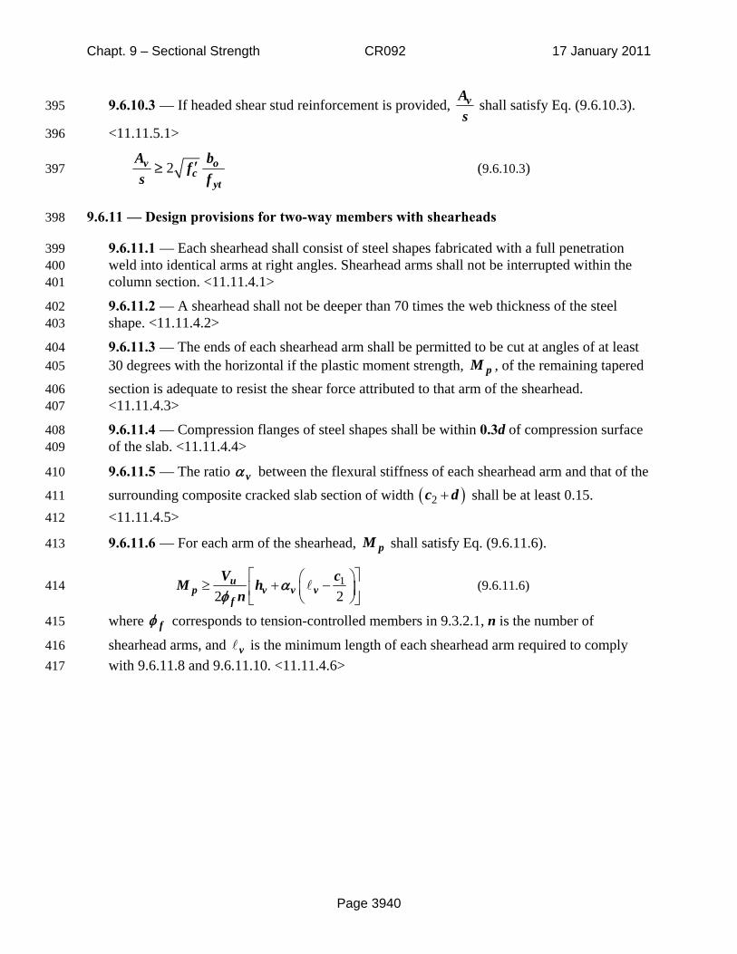
9.6.10.3 — If headed shear stud reinforcement is provided, vAs
shall satisfy Eq. (9.6.10.3). 395
<11.11.5.1> 396
2v oc
yt
A bf
s f′≥ (9.6.10.3) 397
9.6.11 — Design provisions for two-way members with shearheads 398
9.6.11.1 — Each shearhead shall consist of steel shapes fabricated with a full penetration 399 weld into identical arms at right angles. Shearhead arms shall not be interrupted within the 400 column section. <11.11.4.1> 401
9.6.11.2 — A shearhead shall not be deeper than 70 times the web thickness of the steel 402 shape. <11.11.4.2> 403
9.6.11.3 — The ends of each shearhead arm shall be permitted to be cut at angles of at least 404 30 degrees with the horizontal if the plastic moment strength, pM , of the remaining tapered 405
section is adequate to resist the shear force attributed to that arm of the shearhead. 406 <11.11.4.3> 407
9.6.11.4 — Compression flanges of steel shapes shall be within 0.3d of compression surface 408 of the slab. <11.11.4.4> 409
9.6.11.5 — The ratio vα between the flexural stiffness of each shearhead arm and that of the 410
surrounding composite cracked slab section of width ( )2c d+ shall be at least 0.15. 411
<11.11.4.5> 412
9.6.11.6 — For each arm of the shearhead, pM shall satisfy Eq. (9.6.11.6). 413
12 2
up v v v
f
V cM hn
αφ
⎡ ⎤⎛ ⎞≥ + −⎜ ⎟⎢ ⎥⎝ ⎠⎣ ⎦ (9.6.11.6) 414
where fφ corresponds to tension-controlled members in 9.3.2.1, n is the number of 415
shearhead arms, and v is the minimum length of each shearhead arm required to comply 416 with 9.6.11.8 and 9.6.11.10. <11.11.4.6> 417
Chapt. 9 – Sectional Strength CR092 17 January 2011
Page 3941
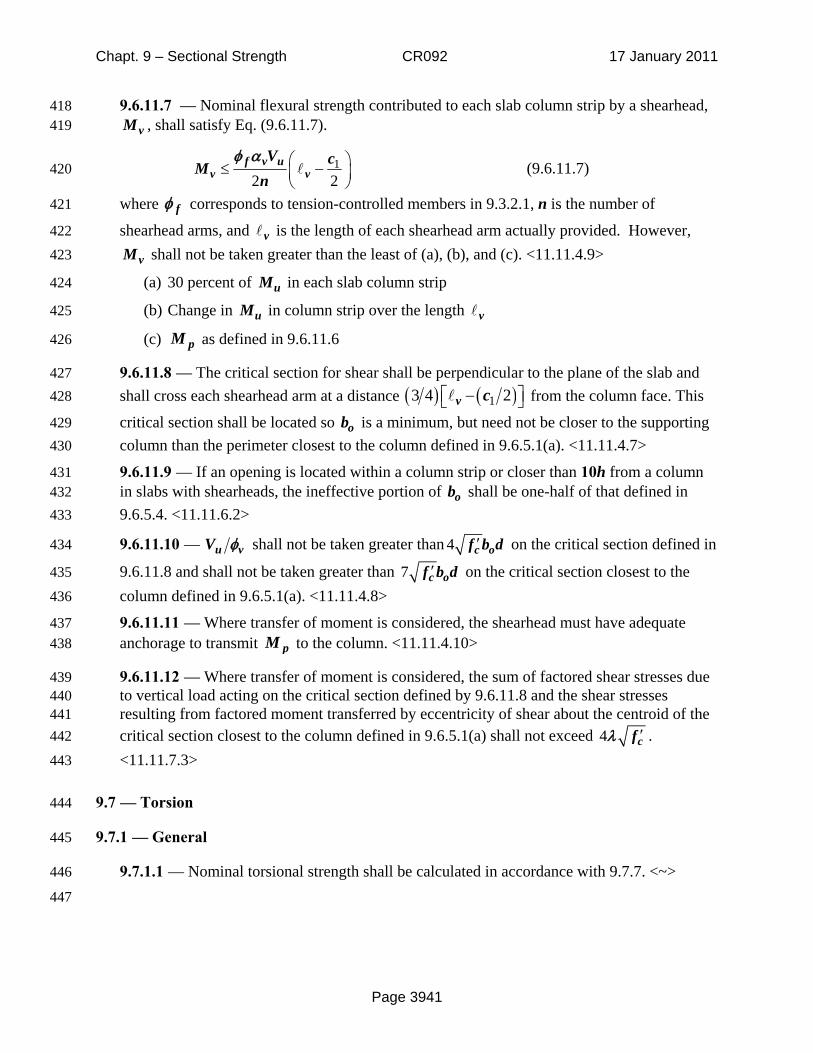
9.6.11.7 — Nominal flexural strength contributed to each slab column strip by a shearhead, 418 vM , shall satisfy Eq. (9.6.11.7). 419
12 2
f v uv v
V cMn
φ α ⎛ ⎞≤ −⎜ ⎟⎝ ⎠
(9.6.11.7) 420
where fφ corresponds to tension-controlled members in 9.3.2.1, n is the number of 421
shearhead arms, and v is the length of each shearhead arm actually provided. However, 422
vM shall not be taken greater than the least of (a), (b), and (c). <11.11.4.9> 423
(a) 30 percent of uM in each slab column strip 424
(b) Change in uM in column strip over the length v 425
(c) pM as defined in 9.6.11.6 426
9.6.11.8 — The critical section for shear shall be perpendicular to the plane of the slab and 427 shall cross each shearhead arm at a distance ( ) ( )13 4 2v c⎡ ⎤−⎣ ⎦ from the column face. This 428
critical section shall be located so ob is a minimum, but need not be closer to the supporting 429 column than the perimeter closest to the column defined in 9.6.5.1(a). <11.11.4.7> 430
9.6.11.9 — If an opening is located within a column strip or closer than 10h from a column 431 in slabs with shearheads, the ineffective portion of ob shall be one-half of that defined in 432 9.6.5.4. <11.11.6.2> 433
9.6.11.10 — u vV φ shall not be taken greater than 4 c of b d′ on the critical section defined in 434
9.6.11.8 and shall not be taken greater than 7 c of b d′ on the critical section closest to the 435
column defined in 9.6.5.1(a). <11.11.4.8> 436
9.6.11.11 — Where transfer of moment is considered, the shearhead must have adequate 437 anchorage to transmit pM to the column. <11.11.4.10> 438
9.6.11.12 — Where transfer of moment is considered, the sum of factored shear stresses due 439 to vertical load acting on the critical section defined by 9.6.11.8 and the shear stresses 440 resulting from factored moment transferred by eccentricity of shear about the centroid of the 441 critical section closest to the column defined in 9.6.5.1(a) shall not exceed 4 cfλ ′ . 442
<11.11.7.3> 443
9.7 — Torsion 444
9.7.1 — General 445
9.7.1.1 — Nominal torsional strength shall be calculated in accordance with 9.7.7. <~> 446
447
Chapt. 9 – Sectional Strength CR092 17 January 2011
Page 3942
9.7.2 — Strength reduction factor 448
9.7.2.1 — Strength reduction factor for torsion, vφ , shall be 0.75. <9.3.2.3> 449
9.7.3 — Limiting material strengths for torsion 450
9.7.3.1 — For torsion, the value of used to calculate thT and crT shall not exceed 451
100 psi. <11.1.2> 452
9.7.3.2 — Value of ytf used to calculate nT shall be in accordance with Table 6.3.4(a). 453
<11.4.2> 454
Reference to 6.3.4 per LB11-1. 455
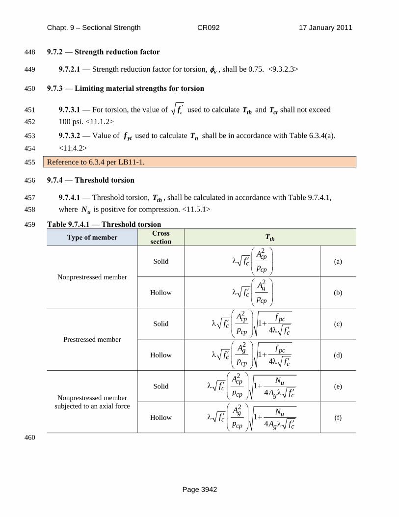
9.7.4 — Threshold torsion 456
9.7.4.1 — Threshold torsion, thT , shall be calculated in accordance with Table 9.7.4.1, 457 where uN is positive for compression. <11.5.1> 458
Table 9.7.4.1 — Threshold torsion 459
Type of member Cross section thT
Nonprestressed member
Solid 2⎛ ⎞
⎜ ⎟′λ⎜ ⎟⎝ ⎠
cpc
cp
Af
p (a)
Hollow 2⎛ ⎞
⎜ ⎟′λ⎜ ⎟⎝ ⎠
gc
cp
Af
p (b)
Prestressed member
Solid 2
14
⎛ ⎞⎜ ⎟′λ +⎜ ⎟ ′λ⎝ ⎠
cp pcc
cp c
A ff
p f (c)
Hollow 2
14
⎛ ⎞⎜ ⎟′λ +⎜ ⎟ ′λ⎝ ⎠
g pcc
cp c
A ff
p f (d)
Nonprestressed member subjected to an axial force
Solid 2
14
⎛ ⎞⎜ ⎟′λ +⎜ ⎟ ′λ⎝ ⎠
cp uc
cp g c
A Nfp A f
(e)
Hollow 2
14
⎛ ⎞⎜ ⎟′λ +⎜ ⎟ ′λ⎝ ⎠
g uc
cp g c
A Nfp A f
(f)
460
cf'

Chapt. 9 – Sectional Strength CR092 17 January 2011
Page 3943
Add to Chapter 2: 461 thT = threshold torsional moment, in.-lb 462
crT =cracking torsional moment, in.-lb 463
9.7.5 — Cracking torsion 464
9.7.5.1 — Cracking torsion, crT , shall be calculated in accordance with Table 9.7.5.1, where 465
uN is positive for compression. <11.5.2> 466
Table 9.7.5.1 — Cracking torsion 467 Type of member crT
Nonprestressed member Solid or Hollow
24
⎛ ⎞⎜ ⎟′λ⎜ ⎟⎝ ⎠
cpc
cp
Af
p (a)
Prestressed member Solid or Hollow
24 1
4
⎛ ⎞⎜ ⎟′λ +⎜ ⎟ ′λ⎝ ⎠
cp pcc
cp c
A ff
p f (b)
Nonprestressed member subjected to an axial force
Solid or Hollow
24 1
4
⎛ ⎞⎜ ⎟′λ +⎜ ⎟ ′λ⎝ ⎠
cp uc
cp g c
A Nfp A f
(c)
9.7.6 — Factored design torsion 468
9.7.6.1 — It shall be permitted to neglect torsional effects if Eq. (9.7.6.1) is satisfied. 469 <11.5.1> 470
u v thT Tφ< (9.7.6.1) 471
9.7.6.2 — If uT in a member is required to maintain equilibrium and exceeds thT , the 472 member shall be designed to resist uT . <11.5.2.1> 473
9.7.6.3 — In a statically indeterminate structure where reduction of uT in a member can 474 occur due to redistribution of internal forces after torsional cracking, uT shall be permitted to 475 be reduced to v crTφ . <11.5.2.2> 476
9.7.6.4 — If uT is redistributed for torsional cracking in accordance with 9.7.6.3, the 477 factored moments and shears used for design of the adjoining members shall be in 478 equilibrium with the reduced torsion. <11.5.2.2> 479

Chapt. 9 – Sectional Strength CR092 17 January 2011
Page 3944
9.7.7 — Torsional strength 480
9.7.7.1 — For prestressed and nonprestressed members, nT shall be calculated as:<11.5.3.6> 481
2coto t yt
nA A f
Ts
θ= (9.7.7.1) 482
where oA shall be determined by analysis and θ shall not be taken smaller than 30 degrees 483 nor larger than 60 degrees. 484
9.7.7.2 — In Eq. (9.7.7.1), it shall be permitted to take oA equal to 0.85 ohA . <11.5.3.6> 485
9.7.7.3 — In Eq. (9.7.7.1), it shall be permitted to take θ equal to (a) or (b): <11.5.3.6> 486
(a) 45 degrees for nonprestressed members or members with effective prestress force less 487 than 40 percent of the tensile strength of the longitudinal reinforcement 488
(b) 37.5 degrees for prestressed members with an effective prestress force of at least 40 489 percent of the tensile strength of the longitudinal reinforcement 490
9.7.8 — Cross-sectional limits 491
9.7.8.1 — If uT exceeds thT , cross-sectional dimensions shall be such that (a) or (b) is 492 satisfied. <11.5.3.1> 493
(a) For solid sections 494
22
2 81.7
⎛ ⎞⎛ ⎞ ⎛ ⎞′+ ≤ φ +⎜ ⎟⎜ ⎟ ⎜ ⎟⎜ ⎟⎝ ⎠ ⎝ ⎠⎝ ⎠
u u h cv c
w woh
V T p V fb d b dA
(9.7.8.1a) 495
(b) For hollow sections 496
2 81.7
⎛ ⎞⎛ ⎞ ⎛ ⎞′+ ≤ φ +⎜ ⎟⎜ ⎟ ⎜ ⎟⎜ ⎟⎝ ⎠ ⎝ ⎠⎝ ⎠
u u h cv c
w woh
V T p V fb d b dA
(9.7.8.1b) 497
9.7.8.2 — For prestressed members, the value of d used in 9.7.8.1 need not be taken less than 498 0.8h. <11.5.3.1> <11.4.3> 499
9.7.8.3 — For hollow sections where the wall thickness varies around the perimeter, 500
Eq. (9.7.8.1b) shall be evaluated at the location where the term 21.7u u h
w oh
V T pb d A
⎛ ⎞⎛ ⎞+ ⎜ ⎟⎜ ⎟ ⎜ ⎟⎝ ⎠ ⎝ ⎠
is a 501
maximum. <11.5.3.2> 502
9.7.8.4 — For hollow sections where the wall thickness is less thanoh
h
Ap , the term 21.7
u h
oh
T pA
⎛ ⎞⎜ ⎟⎜ ⎟⎝ ⎠
503
in Eq. (9.7.8.1b) shall be taken as 1.7
u
oh
TA t
⎛ ⎞⎜ ⎟⎝ ⎠
, where t is the thickness of the wall of the 504
hollow section at the location where the stresses are being checked. <11.5.3.3> 505