Embed Size (px)
Citation preview

HIGHWAY DESIGN MANUAL 850-1 March 7, 2014
CHAPTER 850 PHYSICAL STANDARDS
Topic 851 - General Index 851.1 - Introduction This chapter deals with the selection of drainage facility material type and sizes including pipes, pipe liners, pipe linings, drainage inlets and trench drains.
851.2 Selection of Material and Type The choice of drainage facility material type and size is based on the following factors:
(1) Physical and Structural Factors. Of the many physical and structural considerations, some of the most important are:
(a) Durability.
(b) Headroom.
(c) Earth Loads.
(d) Bedding Conditions.
(e) Conduit Rigidity.
(f) Impact.
(g) Leak Resistance.
(2) Hydraulic Factors. Hydraulic considerations involve:
(a) Design Discharge.
(b) Shape, slope and cross sectional area of channel.
(c) Velocity of approach.
(d) Outlet velocity.
(e) Total available head.
(f) Bedload.
(g) Inlet and outlet conditions.
(h) Slope.
(i) Smoothness of conduit.
(j) Length.
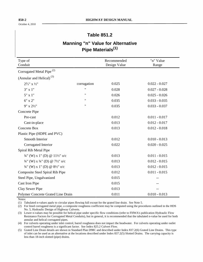
Suggested values for Manning's Roughness coefficient (n) for design purposes are given in
Table 851.2 for each type of conduit. See Index 866.3 for use of Manning's formula.
Topic 852 - Pipe Materials 852.1 Reinforced Concrete Pipe (RCP) (1) Durability. RCP is generally precast prior to
delivery to the project site. The durability of reinforced concrete pipe can be affected by abrasive flows or acids, chlorides and sulfate in the soil and water. See Index 855.2 Abrasion, and Index 855.4 Protection of Concrete Pipe and Drainage Structures from Acids, Chlorides and Sulfates.
The following measures increase the durability of reinforced concrete culverts:
(a) Cover Over Reinforcing Steel. Additional cover over the reinforcing steel should be specified where abrasion is likely to be severe as to appreciably shorten the design service life of a concrete culvert. This extra cover is also warranted under exposure to corrosive environments, see Index 855.4 Protection of Concrete Pipe and Drainage Structures from Acids, Chlorides and Sulfates. Extra cover over the reinforcing steel does not necessarily require extra wall thickness, as it may be possible to provide the additional cover and still obtain the specified D-load with standard wall thicknesses.
(b) Increase cement content.
(c) Reduce water content.
(d) Invert paving/plating.
(2) Indirect Design Strength Requirements.
(a) Design Standards. The “D” load strength of reinforced concrete pipe is determined by the load to produce a 0.01 inch crack under the “3-edge bearing test” called for in AASHTO Designations M 170, M 207M/M 207, and M 206M/M 206 for circular reinforced pipe, oval shaped reinforced pipe, and reinforced concrete pipe arches, respectively.
(b) Height of Fill. See Topic 856.
850-2 HIGHWAY DESIGN MANUAL October 4, 2010
Table 851.2
Manning "n" Value for Alternative Pipe Materials(1)
Type of Recommended "n" Value Conduit Design Value Range
Corrugated Metal Pipe (2)
(Annular and Helical) (3)
2⅔" x ½" corrugation 0.025 0.022 - 0.027 3" x 1" " 0.028 0.027 - 0.028 5" x 1" " 0.026 0.025 - 0.026 6" x 2" " 0.035 0.033 - 0.035 9" x 2½" " 0.035 0.033 - 0.037
Concrete Pipe Pre-cast 0.012 0.011 - 0.017 Cast-in-place 0.013 0.012 - 0.017
Concrete Box 0.013 0.012 - 0.018 Plastic Pipe (HDPE and PVC)
Smooth Interior 0.012 0.010 - 0.013 Corrugated Interior 0.022 0.020 - 0.025
Spiral Rib Metal Pipe ¾" (W) x 1" (D) @ 11½" o/c 0.013 0.011 - 0.015 ¾" (W) x ¾" (D) @ 7½" o/c 0.013 0.012 - 0.015 ¾" (W) x 1" (D) @ 8½" o/c 0.013 0.012 - 0.015
Composite Steel Spiral Rib Pipe 0.012 0.011 - 0.015 Steel Pipe, Ungalvanized 0.015 -- Cast Iron Pipe 0.015 -- Clay Sewer Pipe 0.013 -- Polymer Concrete Grated Line Drain 0.011 0.010 - 0.013 Notes: (1) Tabulated n-values apply to circular pipes flowing full except for the grated line drain. See Note 5. (2) For lined corrugated metal pipe, a composite roughness coefficient may be computed using the procedures outlined in the HDS
No. 5, Hydraulic Design of Highway Culverts. (3) Lower n-values may be possible for helical pipe under specific flow conditions (refer to FHWA's publication Hydraulic Flow
Resistance Factors for Corrugated Metal Conduits), but in general, it is recommended that the tabulated n-value be used for both annular and helical corrugated pipes.
(4) For culverts operating under inlet control, barrel roughness does not impact the headwater. For culverts operating under outlet control barrel roughness is a significant factor. See Index 825.2 Culvert Flow.
(5) Grated Line Drain details are shown in Standard Plan D98C and described under Index 837.2(6) Grated Line Drains. This type of inlet can be used as an alternative at the locations described under Index 837.2(5) Slotted Drains. The carrying capacity is less than 18-inch slotted (pipe) drains.
HIGHWAY DESIGN MANUAL 850-3 March 7, 2014
(3) Shapes. Reinforced concrete culverts are
available in circular and oval shapes. Reinforced Concrete Pipe Arch (RCPA) shapes have been discontinued by West Coast manufacturers.
In general, the circular shaped is the most economical for the same cross-sectional area. Oval shapes are appropriate for areas with limited head or overfill or where these shapes are more appropriate for site conditions. A convenient reference of commercially available products and shapes is the AASHTO publication, “A Guide to Standardized Highway Drainage Products”.
(4) Non-Reinforced Concrete Pipe Option. Non-reinforced concrete pipe may be substituted at the contractor’s option for reinforced concrete pipe for all sizes 36 inches in diameter and smaller as long as it conforms to Section 65 of the Standard Specifications. Non-Reinforced concrete pipe is not affected by chlorides or stray currents and may be used in lieu of RCP in these environments without coating or the need to provide extra cover over reinforcement.
(5) Direct Design Method - RCP. (Contact DES - Structures Design)
852.2 Concrete Box and Arch Culverts (1) Box Culverts. Single and multiple span
reinforced concrete box culverts are completely detailed in the Standard Plans. For cast-in-place construction, strength classifications are shown for 10 feet and 20 feet overfills. Precast reinforced concrete box culverts require a minimum of 1 foot of overfill and are not to exceed 12 feet in span length. Special details are necessary if precast boxes are proposed as extensions for existing box culverts. Where the use of precast box culverts is applicable, the project plans should include them as an alternative to cast-in-place construction. Because the standard measurement and payment clauses for precast RCB’s differ from cast-in-place construction, precast units must be identified as an alternative and the special provision must be appropriately modified.
The standard plan sheets for precast boxes show details which require them to be layed out with joints perpendicular to the centerline of the box. This is a consideration for the design engineer in
situations which require stage construction and when the culvert is to be aligned on a high skew. This situation will require either a longer culvert than otherwise may have been needed, or a special design allowing for skewed joints. Prior to selecting the latter option DES - Structures Design should be consulted.
(2) Concrete Arch Culverts. Technical questions regarding concrete arch culverts should be directed to the Underground Structures Branch of DES - Structures Design.
(3) Three-Sided Concrete Box Culverts Design details for cast-in-place (CIP) construction three-sided bottomless concrete box culverts in 2-foot span increments from 12 feet to < 20 feet, inclusive, with strength classifications shown for 10 feet and 20 feet overfills are available upon request from DES - Structures Design. CIP Bottomless Culvert XS-sheets 17-050-1, 2, 3, 4 and 5 may be obtained electronically. Precast three-sided box culverts are an acceptable alternative to CIP designs, where contractors may submit such designs for approval. Both precast and CIP designs must be placed on a foundation designed specifically for the project site.
(4) Corrosion, Abrasion, and Invert Protection. Refer to Index 855.2 Abrasion, and Index 855.4 Protection of Concrete Pipe and Drainage Structures from Acids, Chlorides and Sulfates for corrosion, abrasion and invert protection of concrete box and arch culverts.
852.3 Corrugated Steel Pipe, Steel Spiral Rib Pipe and Pipe Arches Corrugated steel pipe, steel spiral rib pipe and pipe arches are available in the diameters and arch shapes as indicated on the maximum height of cover tables. For larger diameters, arch spans or special shapes, see Index 852.5. Corrugated steel pipe and pipe arches are available in various corrugation profiles with helical and annular corrugations. Corrugated steel spiral rib pipe is available in several helical corrugation patterns.
(1) Hydraulics. Annular and helical corrugated steel pipe configurations are applicable in the situations where velocity reduction is important or if a culvert is being designed with an inlet control condition. Spiral rib pipe, on the other
850-4 HIGHWAY DESIGN MANUAL March 7, 2014
hand, may be more appropriate for use in stormdrain situations or if a culvert is being designed with an outlet control condition. Spiral rib pipe has a lower roughness coefficient (Manning's “n”) than other corrugated metal pipe profiles.
(2) Durability. The anticipated maintenance-free service life of corrugated steel pipe, steel spiral rib pipe and pipe arch installations is primarily a function of the corrosivity and abrasiveness of the environment into which the pipe is placed. Corrosion potential must be determined from the pH and minimum resistivity tests covered in California Test 643. Abrasive potential must be estimated from bed material that is present and anticipated flow velocities. Refer to Index 855.1 for a discussion of maintenance-free service life and Index 855.2 Abrasion, and Index 855.3 Corrosion.
The following measures are commonly used to prolong the maintenance-free service life of steel culverts:
(a) Galvanizing. Under most conditions plain galvanizing of steel pipe is all that is needed; however, the presence of corrosive or abrasive elements may require additional protection.
• Protective Coatings - The necessity for any coating should be determined considering hydraulic conditions, local experience, possible environmental impacts, and long-term economy. Approved protective coatings are bituminous asphalt, asphalt mastic and polymeric sheet, which can be applied to the inside and/or outside of the pipe; and polyethylene for composite steel spiral ribbed pipe which is a steel spiral ribbed pipe externally pre-coated with a polymeric sheet, and internally polyethylene lined. All of these protective coatings are typically shop-applied prior to delivery to the construction site. Polymeric sheet coating provides much improved corrosion resistance over bituminous coatings and can be considered to typically allow achievement of a 50-year maintenance-free service life
without need to increase thickness of the steel pipe. To ensure that a damaged coating does not lead to premature catastrophic failure, the base steel thickness for pipes that are to be coated with a polymeric sheet must be able to provide a minimum 10-year service life prior to application of the polymeric material. In addition, a bituminous lining or bituminous paving can be applied over a bituminous coating primer on the inside of the pipe for extra corrosion or abrasion protection (see Section 66 of the Standard Specifications).
Citing Section 5650 of the Fish and Game Code, the Department of Fish and Game (DFG) may restrict the use of bituminous coatings on the interior of pipes if they are to be placed in streams that flow continuously or for an extended period (more than 1 to 2 days) after a rainfall event. Their concern is that abraded particles of asphalt could enter the stream and degrade the fish habitat. Where abrasion is unlikely, DFG concerns should be minimal. DFG has indicated that they have no concerns regarding interior application of polymeric sheet coatings, even under abrasive conditions.
Where the materials report indicates that soil side corrosion is expected, a bituminous asphalt coating which is hot-dipped to cover the entire inside and outside of the pipe or an exterior application of polymeric sheet, as provided in the Standard Specifications, combined with galvanizing of steel, is usually effective in forestalling accelerated corrosion on the backfill side of the pipe. Where soil side corrosion is the only, or primary, factor leading to deterioration, the bituminous asphalt protection layer described above is typically expected to add up to 25 years of service life to an uncoated (i.e., plain galvanized) pipe. A polymeric sheet coating is typically expected to provide up to 50-years of service life to an
HIGHWAY DESIGN MANUAL 850-5 March 7, 2014
uncoated pipe. For locations where water side corrosion and/or abrasion is of concern, protective coatings, or protective coatings with pavings, or protective coatings with linings, in combination with galvanizing will add to the culvert service life to a variable degree, depending upon site conditions and type of coating selected. Refer to Index 855.2 Abrasion, and Index 855.3 Corrosion. If hydraulic conditions at the culvert site require a lining on the inside of the pipe or a coating different than that indicated in the Standard Specifications, then the different requirements must be described in the Special Provisions.
• Extra Metal Thickness. Added service life can be achieved by adding metal thickness. However, this should only be considered after protective coatings and pavings have been considered. Since 0.052 inch thick steel culverts is the minimum steel pipe Caltrans allows, it must be limited to locations that are nonabrasive.
See Table 855.2C for estimating the added service life that can be achieved by coatings and invert paving of steel pipes based upon abrasion resistance characteristics.
(b) Aluminized Steel (Type 2). Evaluations of aluminized steel (type 2) pipe in place for over 40 years have provided data that substantiate a design service life with respect to corrosion resistance equivalent to aluminum pipe. Therefore, for pH values between 5.5 and 8.5, and minimum resistivity values in excess of 1500 ohm-cm, 0.064 inch aluminized steel (type 2) is considered to provide a 50 year design service life. Where abrasion is of concern, aluminized steel (type 2) is considered to be roughly equivalent to galvanized steel. Bituminous coatings are not recommended for corrosion protection, but may be used in accordance with Table 855.2C for abrasion resistance. A concrete invert may also be considered where abrasion is of concern.
For pH ranges outside the 5.5 and 8.5 limits or minimum resistivity values below 1500 ohm-cm, aluminized steel (type 2) should not be used. In no case should the thickness of aluminized steel (type 2) be less than the minimum structural requirements for a given diameter of galvanized steel. Refer to Index 855.2 Abrasion, and Index 855.3 Corrosion.
The AltPipe Computer Program is also available to help designers estimate service life for various corrosive/abrasive conditions. See http://www.dot.ca.gov/hq/oppd/altpipe.htm
(3) Strength Requirements. The strength requirements for corrugated steel pipes and pipe arches, fabricated under acceptable methods contained in the Standard Specifications, are given in Tables 856.3A, B, C, & D. For steel spiral rib pipe see Tables 856.3E, F & G.
(a) Design Standards.
• Corrugation Profiles - Corrugated steel pipe and pipe arches are available in 2⅔" x ½", 3" x 1", and 5" x 1" profiles with helical corrugations, and 2⅔" x ½" profiles with annular corrugations. Corrugated steel spiral rib pipe is available in a ¾" x ¾" x 7½" or ¾" x 1" x 11½" helical corrugation pattern. For systems requiring large diameter and/or deeper fill capacity a ¾" x 1" x 8½" helical corrugation pattern is available. Composite steel spiral rib pipe is available in a ¾" x ¾" x 7½" helical ribbed profile.
• Metal Thickness - Corrugated steel pipe and pipe arches are available in the thickness as indicated on Tables 856.3A, B, C & D. Corrugated steel spiral rib pipe is available in the thickness as indicated on Tables 856.3E, F & G. Where a maximum overfill is not listed on these tables, the pipe or arch size is not normally available in that thickness. All pipe sections provided in Table 856.3 meet handling and installation flexibility requirements of AASHTO LRFD. Composite steel spiral rib pipe is
850-6 HIGHWAY DESIGN MANUAL March 7, 2014
available in the thickness as indicated on
Table 856.3G.
• Height of Fill - The allowable overfill heights for corrugated steel and corrugated steel spiral rib pipe and pipe arches for the various diameters or arch sizes and metal thickness are shown on Tables 856.3A, B, C, & D. For corrugated steel spiral rib pipe, overfill heights are shown on Tables 856.3E, F & G. Table 856.3G gives the allowable overfill height for composite steel spiral rib pipe.
(4) Shapes. Corrugated steel pipe, steel spiral rib pipe and pipe arches are available in the diameters and arch shapes as indicated on the maximum height of cover tables. For larger diameters, arch spans or special shapes, see Index 852.5.
(5) Invert Protection. Refer to Index 855.2 Abrasion. Invert protection should be considered for corrugated steel culverts exposed to excessive wear from abrasive flows or corrosive water. Severe abrasion usually occurs when the flow velocity exceeds 12 feet per second to 15 feet per second and contains an abrasive bedload of sufficient volume. When severe abrasion or corrosion is anticipated, special designs should be investigated and considered. Typical invert protection includes invert paving with portland cement concrete with wire mesh reinforcement, and invert lining with metal plate. The paving limits for invert linings are site specific and should be determined by field review. Additional metal thickness will increase service life. Reducing the velocity within the culvert is an effective method of preventing severe abrasion. Index 853.6 provides additional guidance on invert paving with concrete.
(6) Spiral Rib Steel. Galvanized steel spiral rib pipe is fabricated using sheet steel and continuous helical lock seam fabrication as used for helical corrugated metal pipe. The manufacturing complies with Section 66, “Corrugated Metal Pipe,” of the Standard Specifications, except for profile and fabrication requirements. Spiral rib pipe is fabricated with either: three rectangular ribs spaced midway between seams with ribs
3/4" wide x 3/4" high at a maximum rib pitch of 7-1/2 inches, two rectangular ribs and one half-circle rib equally spaced between seams with ribs 3/4" wide x 1" high at a maximum rib pitch of 11-1/2 inches with the half-circle rib diameter spaced midway between the rectangular ribs, or two rectangular ribs equally spaced between seams with ribs 3/4" wide x 1" high at a maximum rib pitch of 8-1/2 inches.
Aluminized steel spiral rib pipe, type 2 (ASSRP) is available in the same sizes as galvanized steel spiral rib and will support the same fill heights (the aluminizing is simply a replacement coating for zinc galvanizing that allows thinner steel to be placed in certain corrosive environments. See Figure 855.3A for the acceptable pH and resistivity ranges for placement of aluminized steel pipes). Tables 856.3E, F & G give the maximum height of overfill for steel spiral rib pipe constructed under the acceptable methods contained in the Standard Specifications and essentials discussed in Index 829.2.
852.4 Corrugated Aluminum Pipe, Aluminum Spiral Rib Pipe and Pipe Arches Corrugated aluminum pipe, aluminum spiral rib pipe and pipe arches are available in the diameters and arch shapes as indicated on the maximum height of cover tables. For larger diameters, arch spans or special shapes see Index 852.6. Corrugated aluminum pipe and pipe arches are available in various corrugation profiles with helical and annular corrugations. Helical corrugated pipe must be specified if anticipated heights of cover exceed the tabulated values for annular corrugated pipe. Non-standard pipe diameters and arch sizes are also available. Aluminum spiral rib pipe is similar to spiral rib steel and is available in several helical corrugation patterns.
(1) Hydraulics. Corrugated aluminum pipe comes in various corrugated profiles. Annular and helical corrugated aluminum pipe configurations are applicable in the situations where velocity reduction is important or if a culvert is being designed with an inlet control condition. Spiral rib pipe, on the other hand, may be more appropriate for use in stormdrain situations or if a culvert is being designed with an outlet control condition. Spiral rib pipe has a lower roughness
HIGHWAY DESIGN MANUAL 850-7 March 7, 2014
coefficient (Manning's “n”) than other corrugated metal pipe profiles.
(2) Durability. Aluminum culverts or stormdrains may be specified as an alternate culvert material. When a 50-year maintenance-free service life of aluminum pipe is required the pH and minimum resistivity, as determined by California Test Method 643, must be known and the following conditions met:
(a) The pH of the soil, backfill, and effluent is within the range of 5.5 and 8.5, inclusive. Bituminous coatings are not recommended for corrosion protection or abrasion resistance. However, a concrete invert lining may be considered. Abrasive potential must be estimated from bed material that is present and anticipated flow velocities. Refer to Index 855.1 for a discussion of maintenance-free service life and Index 855.2 Abrasion, and Index 855.3 Corrosion prior to selecting aluminum as an allowable alternate.
(b) The minimum resistivity of the soil, backfill, and effluent is 1500 ohm-cm or greater.
(c) Aluminum culverts should not be installed in an environment where other aluminum culverts have exhibited significant distress, such as extensive perforation or loss of invert, for whatever reason, apparent or not.
(d) Aluminum may be considered for side drains in environments having the following parameters:
• When pH is between 5.5 and 8.5 and the minimum resistivity is between 500 and 1500 ohm-cm.
• When pH is between 5.0 and 5.5 or between 8.5 and 9.0 and the minimum resistivity is greater than 1500 ohm-cm.
For these conditions, the Corrosion Technology Branch in METS should be contacted to confirm the advisability of using aluminum on specific projects.
(e) Aluminum must not be used as a section or extension of a culvert containing steel sections.
(3) Strength Requirements. The strength requirements for corrugated aluminum pipe and
pipe arches fabricated under the acceptable methods contained in the Standard Specifications, are given in Tables 856.3H, I & J. See Table 856.3K and Table 856.3L for aluminum spiral rib pipe. Tables 856.3H through L are based on the material properties of H-32 temper aluminum. Additional cover heights can be achieved for an aluminum section when H-34 temper material is used. Contact DES-Structures Design for a special design using H-34 temper material.
(a) Design Standards.
• Corrugation Profiles - Corrugated aluminum pipe and pipe arches are available in 2⅔" x ½" and 5" x 1" profiles with helical or annular corrugations. Aluminum spiral rib pipe is available in a ¾" x ¾" x 7½" or a ¾" x 1" x 11½" helical corrugation profile.
• Metal thickness - Corrugated aluminum pipe and pipe arches are available in the thickness as indicated on Tables 856.3H, I & J. Where a maximum overfill is not listed on these tables, the pipe or pipe arch is not normally available in that thickness. All pipe sections provided in Table 856.3 meet handling and installation flexibility requirements of AASHTO LRFD. Aluminum spiral rib pipe are available in the thickness as indicated on Tables 856.3K & L.
• Height of Fill - The allowable overfill heights for corrugated aluminum pipe and pipe arches for various diameters and metal thicknesses are shown on Tables 856.3H, I & J. For aluminum spiral rib pipe, overfill heights are shown on Tables 856.3K, & L.
(4) Shapes. Corrugated aluminum pipe, aluminum spiral rib pipe and pipe arches are available in the diameters and arch shapes as indicated on the maximum height of cover tables. Helical corrugated pipe must be specified if anticipated heights of cover exceed the tabulated values for annular corrugated pipe.
850-8 HIGHWAY DESIGN MANUAL March 7, 2014
For larger diameters, arch spans or special
shapes, see Index 852.5. Non-standard pipe diameters and arch sizes are also available.
(5) Invert Protection. Invert protection of corrugated aluminum is not recommended.
(6) Spiral Rib Aluminum. Aluminum spiral rib pipe is fabricated using sheet aluminum and continuous helical lock seam fabrication as used for helical corrugated metal pipe. The manufacturing complies with Section 66, “Corrugated Metal Pipe,” of the Standard Specifications, except for profile and fabrication requirements. Aluminum spiral rib pipe is fabricated with either: three rectangular ribs spaced midway between seams with ribs 3/4" wide x 3/4" high at a maximum rib pitch of 7-1/2 inches or two rectangular ribs and one half-circle rib equally spaced between seams with ribs 3/4" wide x 1" high at a maximum rib pitch of 11-1/2 inches with the half-circle rib diameter spaced midway between the rectangular ribs. Figure 855.3A should be used to determine the limitations on the use of spiral rib aluminum pipe for the various levels of pH and minimum resistivity.
852.5 Structural Metal Plate (1) Pipe and Arches. Structural plate pipes and
arches are available in steel and aluminum for the diameters and thickness as shown on Tables 856.3M, N, O & P.
(2) Strength Requirements.
(a) Design Standards.
• Corrugation Profiles - Structural plate pipe and arches are available in a 6" x 2" corrugation for steel and a 9" x 2½" corrugation profile for aluminum.
• Metal Thickness - structural plate pipe and pipe arches are available in thickness as indicated on Tables 856.3M, N, O & P.
• Height of Fill - The allowable height of cover over structural plate pipe and pipe arches for the available diameters and thickness are shown on Tables 856.3M, N, O & P.
Where a maximum overfill is not listed on these tables, the pipe or arch size is not normally available in that thickness. All pipe sections provided in Table 856.3 conform to handling and installation flexibility requirements of AASHTO LRFD. Strutting of culverts, as depicted on Standard Plan D88A, is typically necessary if the pipe is used as a vertical shaft or if the backfill around the pipe is being removed in an unbalanced manner.
(b) Basic Premise. To properly use the above mentioned tables, the designer should be aware of the premises on which the tables are based as well as their limitations. The design tables presuppose:
• That bedding and backfill satisfy the terms of the Standard Specifications, the conditions of cover, and pipe or arch size required by the plans and the essentials of Index 829.2.
• That a small amount of settlement will occur under the culvert, equal in magnitude to that of the adjoining material outside the trench.
(c) Limitations. In using the tables, the following restrictions should be kept in mind.
• The values given for each size of structural plate pipe or arch constitute the maximum height of overfill or cover over the pipe or arch for the thickness of metal and kind of corrugation.
• The thickness shown is the structural minimum. For steel pipe or pipe arches, where abrasive conditions are anticipated, additional metal thickness for the invert plate(s) or a paved invert should be provided when required to fulfill the design service life requirements. Table 855.2C may be used. See Index 855.2 Abrasion and Tables 855.2A, 855.2D and 855.2F.
• Where needed, adequate provisions for corrosion resistance must be made to achieve the required design service life
HIGHWAY DESIGN MANUAL 850-9 March 7, 2014
called for in the references mentioned herein.
• Tables 856.3M & P show the limit of heights of cover for structural plate arches based on the supporting soil sustaining a bearing pressure of 3 tons per square foot at the corners.
(d) Special Designs. If the height of overfill exceeds the tabular values, or if the foundation investigation reveals that the supporting soil will not develop the bearing pressure on which the overfill heights for structural plate pipe or pipe arches are based, a special design prepared by DES - Structures Design is required.
(3) Arches. Design details with maximum allowable overfills for structural plate arches, with cast in place concrete footings may be obtained from DES - Structures Design.
(4) Vehicular Underpasses. Design details with maximum allowable overfills for structural plate vehicular underpasses with spans from 12 feet 2 inches to 20 feet 4 inches, inclusive, are given in the Standard Plans. These designs are based on “factored” bearing soil pressures from 2.5 tons per square foot to 11 tons per square foot.
(5) Special Shapes.
(a) Long Span.
• Arch
• Low Profile Arch
• High Profile Arch
(b) Ellipse. (Text Later)
• Vertical
• Horizontal
(6) Tunnel Liner Plate. The primary applications for tunnel liner plate include lining large structures in need of a structural repair, or culvert installations through an existing embankment that can be constructed by conventional tunnel methods. Typically, tunnel liner plate is not used for direct burial applications where structural metal plate pipe is recommended. DES -
Structures Design will prepare designs upon request. See Index 853.7 for structural repairs.
852.6 Plastic Pipe Plastic pipe is a generic term which currently includes two independent materials; the Standard Specifications states plastic pipe shall be made of either high density polyethylene (HDPE) or polyvinyl chloride (PVC) material. See Index 852.6(2)(a) Strength Requirements for allowed materials and wall profile types.
(1) Durability. Caltrans standards regarding the durability of plastic pipe are based on the long term performance of its material properties. Both forms of plastic pipe culverts (HDPE and PVC) exhibit good abrasion resistance and are virtually corrosion free. See Index 855.2 Abrasion and Index 855.5 Material Susceptibility to Fire. Also, see Tables 855.2A, 855.2E and 855.2F. The primary environmental factor currently considered in limiting service life of plastic materials is ultraviolet (UV) radiation, typically from sunlight exposure. While virtually all plastic pipes contain some amount of UV protection, the level of protection is not equal. Polyvinyl chloride resins used for pipe rarely incorporate UV protection (typically Titanium Dioxide) in amounts adequate to offset long term exposure to direct sunlight. Therefore, frequent exposure (e.g., cross culverts with exposed ends) can lead to brittleness and such situations should be avoided. Conversely, testing performed to date on HDPE products conforming to specification requirements for inclusion of carbon black have exhibited adequate UV resistance. PVC pipe exposed to freezing conditions can also experience brittleness and such situations should be avoided if there is potential for impact loadings, such as maintenance equipment or heavy (3" or larger) bedload during periods of freeze. Plastic pipes can also fail from long term stress that leads to crack growth and from chemical degradation. Improvements in plastic resin specifications and testing requirements has led to increased resistance to slow crack growth. Inclusion of anti-oxidants in the material formulation is the most common form of delaying the onset of chemical degradation, but more thorough testing and assessment protocols need to be developed
850-10 HIGHWAY DESIGN MANUAL March 7, 2014
to more accurately estimate long term performance characteristics and durability.
(2) Strength Requirements.
(a) Design Standards
• Materials - Plastic pipe shall be either Type C (corrugated exterior and interior) corrugated polyethylene pipe, Type S (corrugated exterior and smooth interior) corrugated polyethylene pipe, or corrugated polyvinyl chloride pipe.
• Height of Fill - The allowable overfill heights for plastic pipe for various diameters are shown in Tables 856.4 and 856.5.
852.7 Special Purpose Types (1) Smooth Steel. Smooth steel (welded) pipe can be
utilized for drainage facilities under conditions where corrugated metal or concrete pipe will not meet the structural or design service life requirements, or for certain jacked pipe operations (e.g., auger boring).
(2) Composite Steel Spiral Rib Pipe. Composite steel spiral rib pipe is a smooth interior pipe with efficient hydraulic characteristics. See Table 851.2.
Composite steel spiral rib pipe with its interior polyethylene liner exhibits good abrasion resistance and also resists waterside corrosion found in a typical stormdrain or culvert environment. The exterior of the pipe is protected with a polyethylene film, which offers resistance to corrosive backfills. The pipe will meet a 50-year maintenance-free service life under most conditions. See Table 856.3G for allowable height of cover.
(3) Proprietary Pipe. See Index 110.10 for further discussion and guidelines on the use of proprietary items.
Topic 853 - Pipe Liners and Linings for Culvert Rehabilitation
853.1 General This topic discusses alternative pipe liner and pipe lining materials specifically intended for culvert repair and does not include materials used for Trenchless Excavation Construction (e.g., pipe jacking, pipe ramming, augur boring), joint repair, various types of grouting, or standard pipe materials that are presented elsewhere in Chapter 850 and in the Standard Plans and Standard Specifications.
Many new products and techniques have been developed that often make complete replacement with open cut as shown in the Standard Plans unnecessary. When used appropriately, these new products and techniques can benefit the Department in terms of increased mobility, cost, and safety to both the public and contractors. Design Information Bulletin 83 (DIB 83) outlines a collection of procedures that are cost-effective for their location and that will meet the needs of their particular area, supplementing Topic 853. Use the following link: http://www.dot.ca.gov/hq/oppd/dib/dibprg.htm for further information.
853.2 Caltrans Host Pipe Structural Philosophy In general, if the host (i.e., existing) pipe cannot be made capable of sustaining design loads, it should be replaced rather than rehabilitated. This is a conservative approach and when followed eliminates the need to make a detailed evaluation of the liner’s ability to effectively accept and support dead and live loads. Prior to making the decision whether or not to rehabilitate the culvert and/or which method to choose, a determination of the structural integrity of the host pipe must be made. If rehabilitation of the culvert is determined to be a feasible option, existing voids within the culvert backfill or in the base material under the existing culvert identified either by Maintenance (typically as part of their culvert management system) or already noted in the Geotechnical Design Report, should be filled with grout to re-establish its load carrying capability. Therefore, structural considerations for pipe liners are generally limited to their ability to withstand construction handling and/or grouting pressures. When a structural repair is needed, contact
HIGHWAY DESIGN MANUAL 850-11 March 7, 2014
Underground Structures within DES – Structures Design. See Index 853.7.
853.3 Problem Identification and Coordination Before various alternatives for liners or linings can be selected, the first step following a site investigation which may include taking soil and water samples and pipe wall thickness measurements, is to determine the actual cause of the problem. Relative to Caltrans host pipe structural philosophy, the host pipe may be in need of stabilization, rehabilitation or replacement. Further, it will need to be determined if the structure is at the end of its maintenance-free service life, whether it has been damaged by mechanical abrasion, or corrosion (or both) and if there are any changes to the hydrology or habitat (e.g. fish passage). To make these determinations, the Project Engineer should coordinate with the District Maintenance Culvert Inspection team, Hydraulics and Environmental units. Further assistance may be needed from Geotechnical Design, the Corrosion Technology Branch within DES, Underground Structures and/or Structures Maintenance within DES. Prior to a comprehensive inspection either by trained personnel or camera, it may also be necessary to first clean out the culvert. Problem identification and assessment, and coordination with Headquarters and DES, is discussed in greater detail in DIB 83. Use the following link; http://www.dot.ca.gov/hq/oppd/dib/dib83-01-7.htm#7-1-6
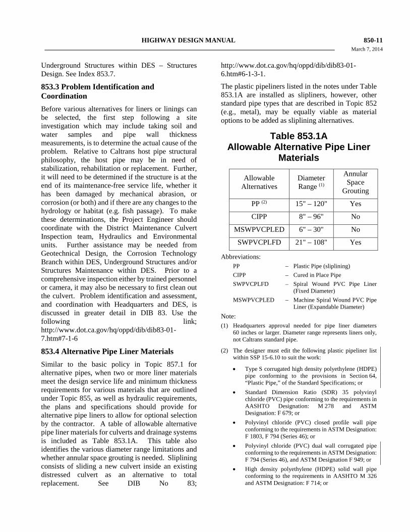
853.4 Alternative Pipe Liner Materials Similar to the basic policy in Topic 857.1 for alternative pipes, when two or more liner materials meet the design service life and minimum thickness requirements for various materials that are outlined under Topic 855, as well as hydraulic requirements, the plans and specifications should provide for alternative pipe liners to allow for optional selection by the contractor. A table of allowable alternative pipe liner materials for culverts and drainage systems is included as Table 853.1A. This table also identifies the various diameter range limitations and whether annular space grouting is needed. Sliplining consists of sliding a new culvert inside an existing distressed culvert as an alternative to total replacement. See DIB No 83;
http://www.dot.ca.gov/hq/oppd/dib/dib83-01-6.htm#6-1-3-1.
The plastic pipeliners listed in the notes under Table 853.1A are installed as slipliners, however, other standard pipe types that are described in Topic 852 (e.g., metal), may be equally viable as material options to be added as sliplining alternatives.
Table 853.1A Allowable Alternative Pipe Liner
Materials Allowable
Alternatives Diameter Range (1)
Annular Space
Grouting
PP (2) 15" – 120" Yes
CIPP 8" – 96" No
MSWPVCPLED 6" – 30" No
SWPVCPLFD 21" – 108" Yes
Abbreviations: PP – Plastic Pipe (sliplining) CIPP – Cured in Place Pipe SWPVCPLFD – Spiral Wound PVC Pipe Liner
(Fixed Diameter) MSWPVCPLED – Machine Spiral Wound PVC Pipe
Liner (Expandable Diameter) Note: (1) Headquarters approval needed for pipe liner diameters
60 inches or larger. Diameter range represents liners only, not Caltrans standard pipe.
(2) The designer must edit the following plastic pipeliner list within SSP 15-6.10 to suit the work:
• Type S corrugated high density polyethylene (HDPE) pipe conforming to the provisions in Section 64, “Plastic Pipe,” of the Standard Specifications; or
• Standard Dimension Ratio (SDR) 35 polyvinyl chloride (PVC) pipe conforming to the requirements in AASHTO Designation: M 278 and ASTM Designation: F 679; or
• Polyvinyl chloride (PVC) closed profile wall pipe conforming to the requirements in ASTM Designation: F 1803, F 794 (Series 46); or
• Polyvinyl chloride (PVC) dual wall corrugated pipe conforming to the requirements in ASTM Designation: F 794 (Series 46), and ASTM Designation F 949; or
• High density polyethylene (HDPE) solid wall pipe conforming to the requirements in AASHTO M 326 and ASTM Designation: F 714; or
850-12 HIGHWAY DESIGN MANUAL March 7, 2014
• Large diameter high density polyethylene (HDPE)
closed profile wall pipe conforming to the requirements in ASTM Designation: F 894.
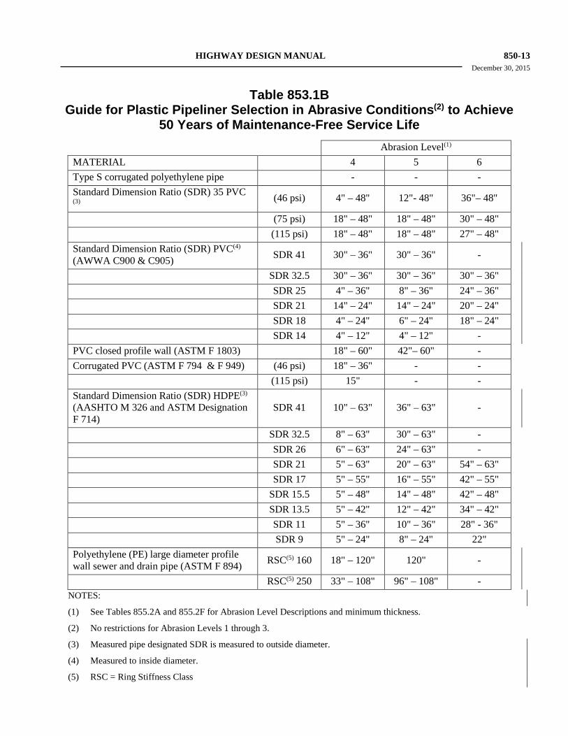
Table 853.1B provides a guide for plastic pipeliner selection in abrasive conditions to achieve a 50-year maintenance-free service life.
For further information on sliplining using plastic pipe liners including available dimensions and stiffness, see DIB 83. Use the following link: http://www.dot.ca.gov/hq/oppd/dib/dib83-01-6.htm#6-1-3-1-1
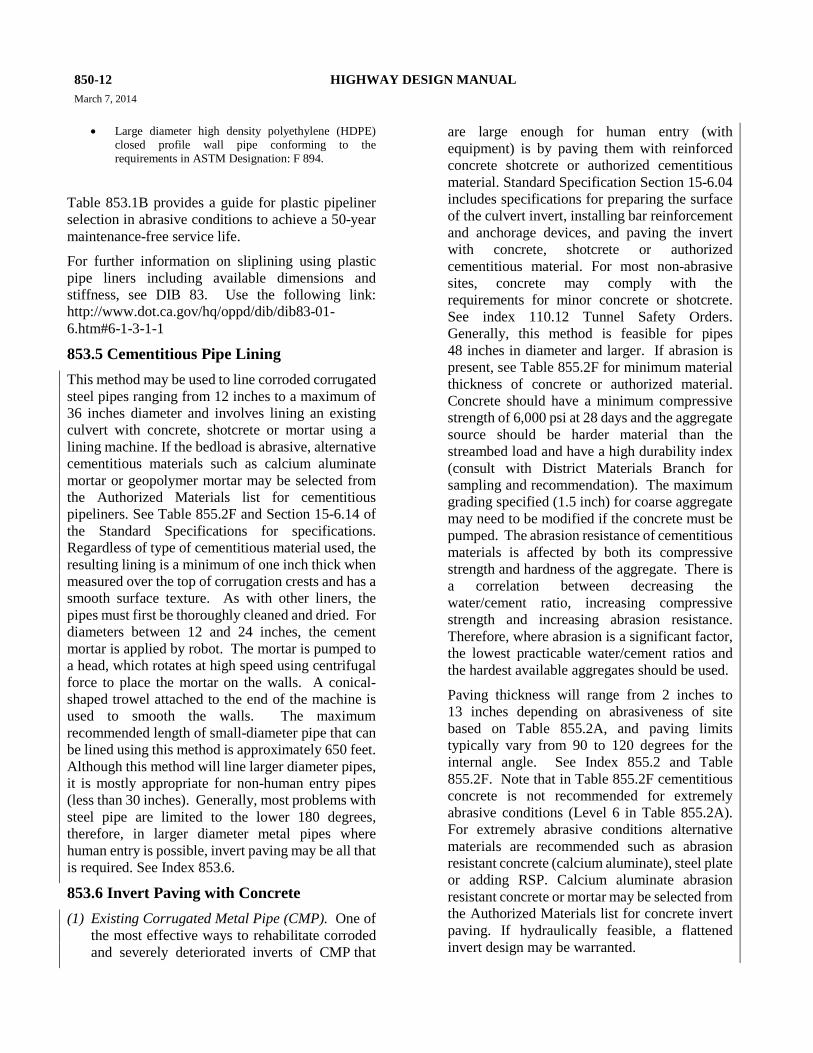
853.5 Cementitious Pipe Lining This method may be used to line corroded corrugated steel pipes ranging from 12 inches to a maximum of 36 inches diameter and involves lining an existing culvert with concrete, shotcrete or mortar using a lining machine. If the bedload is abrasive, alternative cementitious materials such as calcium aluminate mortar or geopolymer mortar may be selected from the Authorized Materials list for cementitious pipeliners. See Table 855.2F and Section 15-6.14 of the Standard Specifications for specifications. Regardless of type of cementitious material used, the resulting lining is a minimum of one inch thick when measured over the top of corrugation crests and has a smooth surface texture. As with other liners, the pipes must first be thoroughly cleaned and dried. For diameters between 12 and 24 inches, the cement mortar is applied by robot. The mortar is pumped to a head, which rotates at high speed using centrifugal force to place the mortar on the walls. A conical-shaped trowel attached to the end of the machine is used to smooth the walls. The maximum recommended length of small-diameter pipe that can be lined using this method is approximately 650 feet. Although this method will line larger diameter pipes, it is mostly appropriate for non-human entry pipes (less than 30 inches). Generally, most problems with steel pipe are limited to the lower 180 degrees, therefore, in larger diameter metal pipes where human entry is possible, invert paving may be all that is required. See Index 853.6.
853.6 Invert Paving with Concrete (1) Existing Corrugated Metal Pipe (CMP). One of
the most effective ways to rehabilitate corroded and severely deteriorated inverts of CMP that
are large enough for human entry (with equipment) is by paving them with reinforced concrete shotcrete or authorized cementitious material. Standard Specification Section 15-6.04 includes specifications for preparing the surface of the culvert invert, installing bar reinforcement and anchorage devices, and paving the invert with concrete, shotcrete or authorized cementitious material. For most non-abrasive sites, concrete may comply with the requirements for minor concrete or shotcrete. See index 110.12 Tunnel Safety Orders. Generally, this method is feasible for pipes 48 inches in diameter and larger. If abrasion is present, see Table 855.2F for minimum material thickness of concrete or authorized material. Concrete should have a minimum compressive strength of 6,000 psi at 28 days and the aggregate source should be harder material than the streambed load and have a high durability index (consult with District Materials Branch for sampling and recommendation). The maximum grading specified (1.5 inch) for coarse aggregate may need to be modified if the concrete must be pumped. The abrasion resistance of cementitious materials is affected by both its compressive strength and hardness of the aggregate. There is a correlation between decreasing the water/cement ratio, increasing compressive strength and increasing abrasion resistance. Therefore, where abrasion is a significant factor, the lowest practicable water/cement ratios and the hardest available aggregates should be used.
Paving thickness will range from 2 inches to 13 inches depending on abrasiveness of site based on Table 855.2A, and paving limits typically vary from 90 to 120 degrees for the internal angle. See Index 855.2 and Table 855.2F. Note that in Table 855.2F cementitious concrete is not recommended for extremely abrasive conditions (Level 6 in Table 855.2A). For extremely abrasive conditions alternative materials are recommended such as abrasion resistant concrete (calcium aluminate), steel plate or adding RSP. Calcium aluminate abrasion resistant concrete or mortar may be selected from the Authorized Materials list for concrete invert paving. If hydraulically feasible, a flattened invert design may be warranted.
HIGHWAY DESIGN MANUAL 850-13 December 30, 2015
Table 853.1B Guide for Plastic Pipeliner Selection in Abrasive Conditions(2) to Achieve
50 Years of Maintenance-Free Service Life Abrasion Level(1) MATERIAL 4 5 6 Type S corrugated polyethylene pipe - - -
Standard Dimension Ratio (SDR) 35 PVC (3) (46 psi) 4" – 48" 12"- 48" 36"– 48"
(75 psi) 18" – 48" 18" – 48" 30" – 48" (115 psi) 18" – 48" 18" – 48" 27" – 48"
Standard Dimension Ratio (SDR) PVC(4) (AWWA C900 & C905) SDR 41 30" – 36" 30" – 36" -
SDR 32.5 30" – 36" 30" – 36" 30" – 36" SDR 25 4" – 36" 8" – 36" 24" – 36" SDR 21 14" – 24" 14" – 24" 20" – 24" SDR 18 4" – 24" 6" – 24" 18" – 24" SDR 14 4" – 12" 4" – 12" - PVC closed profile wall (ASTM F 1803) 18" – 60" 42"– 60" - Corrugated PVC (ASTM F 794 & F 949) (46 psi) 18" – 36" - - (115 psi) 15" - -
Standard Dimension Ratio (SDR) HDPE(3) (AASHTO M 326 and ASTM Designation F 714)
SDR 41 10" – 63" 36" – 63" -
SDR 32.5 8" – 63" 30" – 63" - SDR 26 6" – 63" 24" – 63" - SDR 21 5" – 63" 20" – 63" 54" – 63" SDR 17 5" – 55" 16" – 55" 42" – 55" SDR 15.5 5" – 48" 14" – 48" 42" – 48" SDR 13.5 5" – 42" 12" – 42" 34" – 42" SDR 11 5" – 36" 10" – 36" 28" - 36" SDR 9 5" – 24" 8" – 24" 22"
Polyethylene (PE) large diameter profile wall sewer and drain pipe (ASTM F 894) RSC(5) 160 18" – 120" 120" -
RSC(5) 250 33" – 108" 96" – 108" - NOTES:
(1) See Tables 855.2A and 855.2F for Abrasion Level Descriptions and minimum thickness.
(2) No restrictions for Abrasion Levels 1 through 3.
(3) Measured pipe designated SDR is measured to outside diameter.
(4) Measured to inside diameter.
(5) RSC = Ring Stiffness Class
850-14 HIGHWAY DESIGN MANUAL March 7, 2014
Consult the District Hydraulic Branch for a
recommendation.
Where there is significant loss of the pipe invert, it may be necessary to tie the concrete to more structurally sound portions of the pipe wall in order to transfer compressive thrust of culvert walls into the invert slab to create a “mechanical” connection using welding studs, angle iron or by other means. When a mechanical connection is used, paving limits may vary up to 180 degrees for the internal angle. These types of repairs should be treated as a special design and consultation with the Headquarters Office of Highway Drainage Design within the Division of Design and the Underground Structures unit of Structures Design within the Division of Engineering Services (DES) is advised. Depending on the size of the culvert being paved, pipes with significant invert loss often also have a significant loss of structural backfill with voids present. Where large voids are present, consultation with Geotechnical Services within the Division of Engineering Services (DES) is advised to develop a grouting plan.
See DIB 83 for some invert paving case studies using the following link: http://www.dot.ca.gov/hq/oppd/dib/dib83-01-12.htm#h
(2) Existing RCB and RCP. For existing reinforced concrete boxes (RCB) and reinforced concrete pipes (RCP) with worn inverts and exposed reinforcing steel (generally from abrasive bedloads), the same paving thickness considerations outlined under Index 853.6(1) will apply. However, depending on the structural condition, the existing steel reinforcement may need to be augmented. Consultation with Structures Maintenance and Underground Structures within DES is recommended.
(3) Existing Plastic Pipe. Generally, concrete invert paving is not feasible for plastic pipes because the cement will not adhere to plastic. However, it may be possible to create a “mechanical” connection by other means but these types of repairs should be treated as a special design and consultation with the Headquarters Office of Highway Drainage Design within the Division of Design and the Underground Structures unit of
Structures Design within the Division of Engineering Services (DES) is advised.
853.7 Structural Repairs with Steel Tunnel Liner Plate Cracks in RCP greater than 0.1 inch in width and flexible metal pipes with deflections beyond 10 – 12 percent may indicate a serious condition. When replacement is not an option for existing human entry pipes in need of structural repair, an inspection by Structures Maintenance and a structural analysis by Underground Structures within DES are recommended. Further assistance may be needed from Geotechnical Design and/or the Corrosion Unit within DES.
Two flange or four flange steel tunnel liner plate can be specially designed by Underground Structures within DES as a structural repair to accommodate all live and dead loads. The flange plate lap joints facilitate internal bolt connections (structural metal plate requires access to both sides). After the rings have been installed, the annular space between the liner plates and the host pipe is grouted.
Topic 854 - Pipe Connections 854.1 Basic Policy The Standard Specifications set forth general performance requirements for transverse field joints in all types of culvert and drainage pipe used for highway construction.
Table 857.2 indicates the alternative types of joints that are to be specified for different arch and circular pipe installations with regard to joint strength. The two joint strength types specified for culvert and drainage systems are identified as “standard” and “positive.”
(1) Joint Strength. Joint strength is to be designated on the culvert list.
(a) Standard Joints. The “standard” joint is usually for pipes or arches not subject to large soil movement or disjointing forces. These “standard” joints are satisfactory for ordinarily installations, where tongue and groove or simple slip type joints are typically used. The “standard” joint type is generally adequate for underdrains.
HIGHWAY DESIGN MANUAL 850-15 March 7, 2014
(b) Positive Joints. “Positive” joints are for
more adverse conditions such as the need to withstand soil movements or resist disjointing forces. Examples of these conditions are steep slopes, sharp curves, and poor foundation conditions. See Index 829.2 for additional discussion. “Positive” joints should always be designated on the culvert list for siphon installations.
(c) Downdrain Joints. Pipe “downdrain” joints are designed to withstand high velocity flows, and to prevent leaking and disjointing that could cause failure.
(d) Joint Strength Properties. A description of the specified joint strength properties tabulated in Section 61 “Culvert and Drainage Pipe Joints” of the Standard Specifications is as follows:
• Shear Strength. The shear strength required of the joint is expressed as a percentage of the calculated shear strength of the pipe at a transverse section remote from the joint. All joints, including any connections must be capable of transferring the required shear across the joint.
• Moment Strength. The moment strength required of the joint is expressed as a percent of the calculated moment capacity of the pipe on a transverse section remote from the joint.
• Tensile Strength. The tensile strength is that which resist the longitudinal force which tends to separate (disjoint) adjacent pipe sections.
• Joint Overlap.
Integral Preformed Joint. The Joint overlap is the amount of protection of one culvert barrel into the adjacent culvert barrel by the amount specified for the size of pipe designated. The amount of required overlap will vary based on several factors (material type, diameter, etc.) and is designated on the Standard Plans and/or Standard Specifications.
Any part of an installed joint that has less than ¼ inch overlap will be considered disjointed. Whenever the plans require that the culvert be constructed on a curve, specially manufactured sections of culvert will be required if the design joint cannot meet the minimum ¼ inch overlap requirement after the culvert section is placed on the specified curve.
• Sleeve Joints. The joint overlap is the minimum sleeve width (typically defined by the width of a coupling band) required to engage both the culvert barrels which are abutted to each other.
(2) Joint Leakage. The ability of a pipe joint to prevent the passage of either soil particles or water defines its soiltightness or watertightness. These terms are relative and do not mean that a joint will be able to completely stop the movement of soil or water under all conditions. Any pipe joint that allows significant soil migration (piping) will ultimately cause damage to the embankment, the roadway, or the pipe itself. Therefore, site conditions, such as soil particle size, presence of groundwater, potential for pressure flow, etc., must be evaluated to determine the appropriate joint requirement. Other than solvent or fusion welded joints, almost all joints can exhibit some amount of leakage. Joint performance is typically defined by maximum allowable opening size in the joint itself or by the ability to pass a standardized pressure test. The following criteria should be used, with the allowable joint type(s) indicated on the project plans:
• Normal Joint. Many pipe joint systems are not defined as either soiltight or watertight. However, for the majority of applications, such as culverts or storm drains placed in well graded backfill and surrounding soils containing a minimum of fines; no potential for groundwater contact; limited internal pressure, hydraulic grade line below the pavement grade, etc., this type of joint is acceptable. All currently accepted joint types will meet or exceed “Normal Joint” requirements. The following non-gasketed joint types should not be used beyond the “Normal Joint” criteria range:
850-16 HIGHWAY DESIGN MANUAL March 7, 2014
CMP -Annular -Hat -Helical -Hugger -2-piece Integral Flange -Universal PLASTIC -Split Coupler -Bell/Spigot
• Soiltight Joint. This category includes those joints which would provide an enhanced level of security against leakage and soil migration over the normal joint. One definition of a soiltight joint is contained in Section 26.4.2.4(e) of the AASHTO Standard Specifications for Highway Bridges. In part, this specification requires that if the size of the opening through which soil might migrate exceeds 1/8 inch, the length of the channel (length of path along which the soil particle must travel, i.e., the coupling length) must exceed 4 times the size of the opening. Alternatively, AASHTO allows the joint to pass a hydrostatic test (subjected to approx. 4.6 feet of head) without leaking to be considered soiltight. Typical pipe joints that can meet this criteria are:
RCP and -Flared Bell NRCP -Flushed Bell -Steel Joint-Flush Bell
-Single or Double Offset Design (Flared or Flushed Bell)
-Double Gasket -Tongue and Groove* -Self-Centering T & G*
CMP and -Annular w/gasket
SSRP -Hat w/gasket -Helical w/gasket -Hugger w/gasket -2-piece Int. Fl. w/gasket -Universal w/gasket
CSSRP -Cuffed end w/gasket
PLASTIC -Split Coupler w/gasket (premium) -Bell/Spigot w/gasket
* Where substantial differential settlement
is anticipated, would only meet Normal Joint criteria.
Where soil migration is of concern, but leakage rate is not, a soiltight joint can be achieved in most situations by external wrapping of the joint area with filter fabric (see Index 831.4). Joints listed under both the normal joint and soiltight joint categories, with a filter fabric wrap, would be suitable in these conditions and would not require a gasket or sealant. In many cases, fabric wrapping can be less expensive than a rubber gasket or other joint sealant. Coordination with the District Materials Unit is advised to ensure that the class of filter fabric will withstand construction handling and screen fine soil particles from migrating through the joint.
• Watertight Joint. Watertight joints are specified when the potential for soil erosion or infiltration/exfiltration must be restricted, such as for downdrains, culverts in groundwater zones, etc. Watertight joint requirements are typically met by the use of rubber gasket materials as indicated in the Standard Specifications. The watertight certification test described in Standard Specification Section 61 requires that no leakage occur when a joint is tested for a period of 10 minutes while subjected to a head of 10 feet over the crown of the pipe. This is a test that is typically performed in a laboratory under optimal conditions not typical of those found in the field. Where an assurance of water tightness is needed, a field test should be specified. Designers should be aware that field tests can be relatively expensive, and should only be required if such assurance is critical. A field leakage rate in the range of 700 gallons to 1,000 gallons per inch of nominal diameter per mile of pipe length per day, with a hydrostatic head of 6 feet above the crown of the pipe, is not unusual for joints that pass the
HIGHWAY DESIGN MANUAL 850-17 March 7, 2014
watertight certification test, and is sufficiently watertight for well graded, quality backfill conditions. Where conditions are more sensitive, a lower rate should be specified. Rates below 50 to 100 gallons per inch per mile per day are difficult to achieve and would rarely be necessary. For example, sanitary sewers are rarely required to have leakage rates below 200 gallons per inch per mile per day, even though they have stringent health and environmental restrictions. Field hydrostatic tests are typically conducted over a period of 24 hours or more to establish a valid leakage rate. Designers should also be aware that non-circular pipe shapes (CMP pipe arches, RCP oval shapes, etc.) should not be considered watertight even with the use of rubber gaskets or other sealants due to the lack of uniform compression around the periphery of the joint. Additionally, watertight joints specified for pressure pipe or siphon applications must meet the requirements indicated in Standard Specification Sections 65 and 66. Pipe joints that meet Standard Specification Section 61 water-tightness performance criteria are:
RCP and -Flared Bell NRCP -Flushed Bell
-Steel Joint-Flush Bell -Single or Double Offset
Design (Flared or Flushed Bell)
-Double Gasket
CMP and -Hugger Bands (H-10, 12) SSRP w/gasket and double bolt bar -Annular Band w/gasket -Two Piece Integral Flange w/sleeve-type gasket* PLASTIC -Bell/Spigot w/gasket * Acceptable as a watertight pipe only in
downdrain applications and in 6, 8 and 10 inch diameters. Factory applied sleeve-type gaskets are to be used instead of O-ring or other sealants.
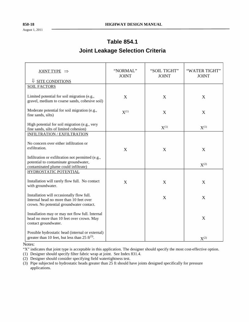
Table 854.1 provides information to help the designer select the proper joint under most conditions.
Topic 855 - Design Service Life 855.1 Basic Concepts The prediction of design service life of drainage facilities is difficult because of the large number of variables, continuing changes in materials, wide range of environments, and use of various protective coatings. The design service life of a drainage facility is defined as the expected maintenance-free service period of each installation. After this period, it is anticipated major will be needed for the facility to perform as originally designed for further periods.
For all metal pipes and arches that are listed in Table 857.2, maintenance-free service period, with respect to corrosion, abrasion and/or durability, is the number of years from installation until the deterioration reaches the point of perforation at any location on the culvert (See Figures 855.3A, 855.3B, and Tables 855.2D and 855.2F). AltPipe can be used to estimate service life of all circular metal pipe. See Index 857.2 Alternative Pipe Culvert Selection Procedure Using AltPipe.
For reinforced concrete pipe (RCP), box (RCB) and arch (RCA) culverts, maintenance-free service period, with respect to corrosion, abrasion and/or durability, is the number of years from installation until the deterioration reaches the point of exposed reinforcement at any point on the culvert. AltPipe can be used to estimate service life of reinforced concrete pipe (RCP), but not RCB, RCA or NRCP. See Index 857.2 Alternative Pipe Culvert Selection Procedure Using AltPipe.
For non-reinforced concrete pipe culverts (NRCP), maintenance-free service period, with respect to corrosion, abrasion and/or durability, is the number of years from installation until the deterioration reaches the point of perforation or major cracking with soil loss at any point on the culvert.
For plastic pipe, maintenance-free service period, with respect to corrosion, abrasion, and long term structural performance, is the number of years from installation until the deterioration reaches the point
850-18 HIGHWAY DESIGN MANUAL August 1, 2011
Table 854.1
Joint Leakage Selection Criteria
JOINT TYPE ⇒ ⇓ SITE CONDITIONS
“NORMAL” JOINT
“SOIL TIGHT” JOINT
“WATER TIGHT” JOINT
SOIL FACTORS Limited potential for soil migration (e.g., gravel, medium to coarse sands, cohesive soil) Moderate potential for soil migration (e.g., fine sands, silts) High potential for soil migration (e.g., very fine sands, silts of limited cohesion)
X
X(1)
X
X
X(1)
X
X
X(1)
INFILTRATION / EXFILTRATION No concern over either infiltration or exfiltration. Infiltration or exfiltration not permitted (e.g., potential to contaminate groundwater, contaminated plume could infiltrate)
X
X
X
X(2)
HYDROSTATIC POTENTIAL Installation will rarely flow full. No contact with groundwater. Installation will occasionally flow full. Internal head no more than 10 feet over crown. No potential groundwater contact. Installation may or may not flow full. Internal head no more than 10 feet over crown. May contact groundwater. Possible hydrostatic head (internal or external) greater than 10 feet, but less than 25 ft(3).
X
X
X
X
X
X
X(2)
Notes: “X” indicates that joint type is acceptable in this application. The designer should specify the most cost-effective option. (1) Designer should specify filter fabric wrap at joint. See Index 831.4. (2) Designer should consider specifying field watertightness test. (3) Pipe subjected to hydrostatic heads greater than 25 ft should have joints designed specifically for pressure
applications.
HIGHWAY DESIGN MANUAL 850-19 November 2, 2009
of perforation at any location on the culvert or until the pipe material has lost structural load carrying capacity typically represented by wall buckling or excessive deflection/deformation. AltPipe can be used to estimate service life of all plastic pipe. See Index 857.2 Alternative Pipe Culvert Selection Procedure Using AltPipe. All types of culverts are subject to deterioration from corrosion, or abrasion, or material degradation.
Corrosion may result from active elements in the soil, water and/or atmosphere. Abrasion is a result of mechanical wear and depends upon the frequency, duration and velocity of flow, and the amount and character of bedload. Material degradation may result from material quality, UV exposure, or long term material structural performance.
To assure that the maintenance-free service period is achieved, alternative metal pipe may require added thickness and/or protective coatings. Concrete pipe may require extra thickness of concrete cover over the steel reinforcement, high density concrete, using supplementary cementitious materials, epoxy coated reinforcing steel, and/or protective coatings. Means for estimating the maintenance-free service life of pipe, and techniques for extending the useful life of pipe materials are discussed in more detail in Topic 852.
The design service life for drainage facilities for all projects should be as follows:
(1) Culverts, Drainage Systems, and Side Drains.
(a) Roadbed widths greater than 28 feet - 50 years.
(b) Greater than 10 feet of cover - 50 years.
(c) Roadbed widths 28 feet or less and with less than 10 feet of cover - 25 years.
(d) Installations under interim alignment - 25 years.
(2) Overside Drains.
(a) Buried more than 3 feet- 50 years.
(b) All other conditions, such as on the surface of fill slopes - 25 years.
(3) Subsurface Drains.
(a) Underdrains within roadbed - 50 years.
(b) Underdrains outside of roadbed - 25 years.
(c) Stabilization trench drains - 50 years.
In case of conflict in the design service life requirements between the above controls, the highest design service life is required except for those cases of interim alignment with more than 10 feet of cover. For temporary construction, a lesser design service life than that shown above is acceptable.
Where the above indicates a minimum design service life of 25 years, 50 years may be used. For example an anticipated change in traffic conditions or when the highway is considered to be on permanent alignment may warrant the higher design service life.
855.2 Abrasion All types of pipe material are subject to abrasion and can experience structural failure around the pipe invert if not adequately protected. Abrasion is the wearing away of pipe material by water carrying sands, gravels and rocks (bed load) and is dependent upon size, shape, hardness and volume of bed load in conjunction with volume, velocity, duration and frequency of stream flow in the culvert. For example, at independent sites with a similar velocity range, bedloads consisting of small and round particles will have a lower abrasion potential than those with large and angular particles such as shattered or crushed rocks. Given different sites with similar flow velocities and particle size, studies have shown the angularity and/or volume of the material may have a significant impact to the abrasion potential of the site. Likewise, two sites with similar site characteristics, but different hydrologic characteristics, i.e., volume, duration and frequency of stream flow in the culvert, will probably also have different abrasion levels.
In Table 855.2A six abrasion levels have been defined to assist the designer in quantifying the abrasion potential of a site. The designer is encouraged to use the guidelines provided in Table 855.2A in conjunction with Table 855.2B “Bed Materials Moved by Various Flow Depths and Velocities” and the abrasion history of a site (if available) to achieve the required service life for a pipe, coating or invert lining material. Sampling of the streambed materials generally is not necessary, but visual examination and documentation of the
850-20 HIGHWAY DESIGN MANUAL March 7, 2014
size, shape and volume of abrasive materials in the streambed and estimating the average stream slope will provide the designer data needed to determine the expected level of abrasion. Where an existing culvert is in place, the condition of the invert and estimated combined wear rate due to abrasion and corrosion based on remaining pipe thickness measurements or if it is known approximately when first perforation occurred (steel pipe only), should always be used first. Figure 855.3B should be used to estimate the expected loss due to corrosion for steel pipe.
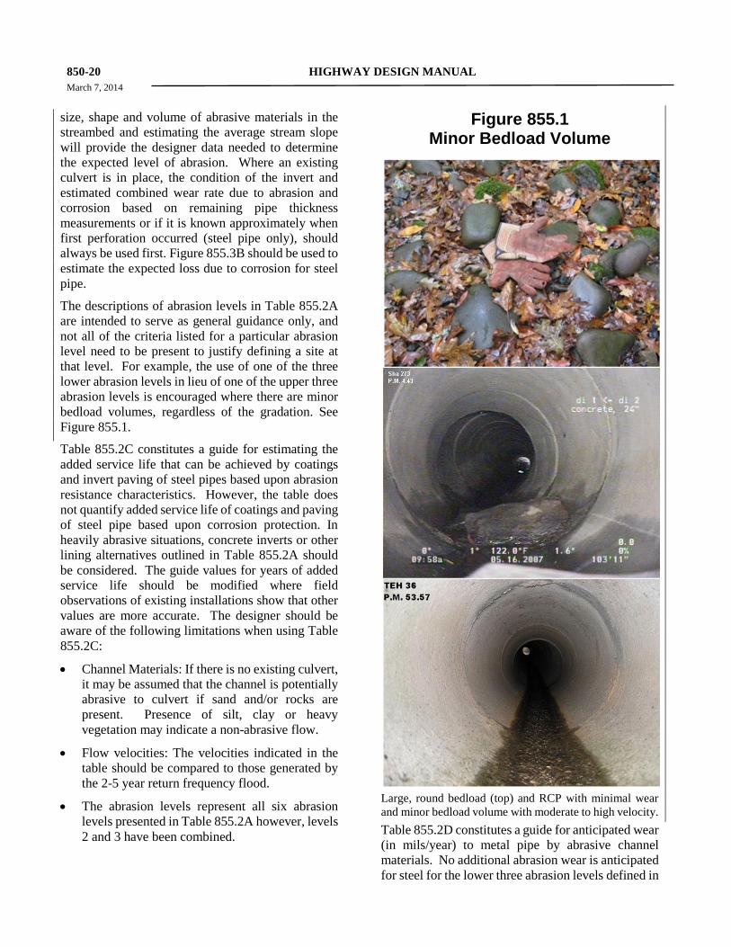
The descriptions of abrasion levels in Table 855.2A are intended to serve as general guidance only, and not all of the criteria listed for a particular abrasion level need to be present to justify defining a site at that level. For example, the use of one of the three lower abrasion levels in lieu of one of the upper three abrasion levels is encouraged where there are minor bedload volumes, regardless of the gradation. See Figure 855.1.
Table 855.2C constitutes a guide for estimating the added service life that can be achieved by coatings and invert paving of steel pipes based upon abrasion resistance characteristics. However, the table does not quantify added service life of coatings and paving of steel pipe based upon corrosion protection. In heavily abrasive situations, concrete inverts or other lining alternatives outlined in Table 855.2A should be considered. The guide values for years of added service life should be modified where field observations of existing installations show that other values are more accurate. The designer should be aware of the following limitations when using Table 855.2C:
• Channel Materials: If there is no existing culvert, it may be assumed that the channel is potentially abrasive to culvert if sand and/or rocks are present. Presence of silt, clay or heavy vegetation may indicate a non-abrasive flow.
• Flow velocities: The velocities indicated in the table should be compared to those generated by the 2-5 year return frequency flood.
• The abrasion levels represent all six abrasion levels presented in Table 855.2A however, levels 2 and 3 have been combined.
Figure 855.1 Minor Bedload Volume
Large, round bedload (top) and RCP with minimal wear and minor bedload volume with moderate to high velocity. Table 855.2D constitutes a guide for anticipated wear (in mils/year) to metal pipe by abrasive channel materials. No additional abrasion wear is anticipated for steel for the lower three abrasion levels defined in
HIGHWAY DESIGN MANUAL 850-21 November 2, 2009
Table 855.2A, because it is assumed that there is some degree of abrasion incorporated within California Test 643 and Figure 855.3B. Figure 855.3B, “Chart for Estimating Years to Perforation of Steel Culverts,” is part of a Standard California Department of Transportation Test Method derived from highway culvert investigations. This chart alone is not used for determining service life because it does not consider the effects of abrasion or overfill; it is for estimating the years to the first corrosion perforation of the wall or invert of the CSP. Additional gauge thickness or invert protection may be needed if the thickness for structural requirements (i.e., for overfill) is inadequate for abrasion potential.
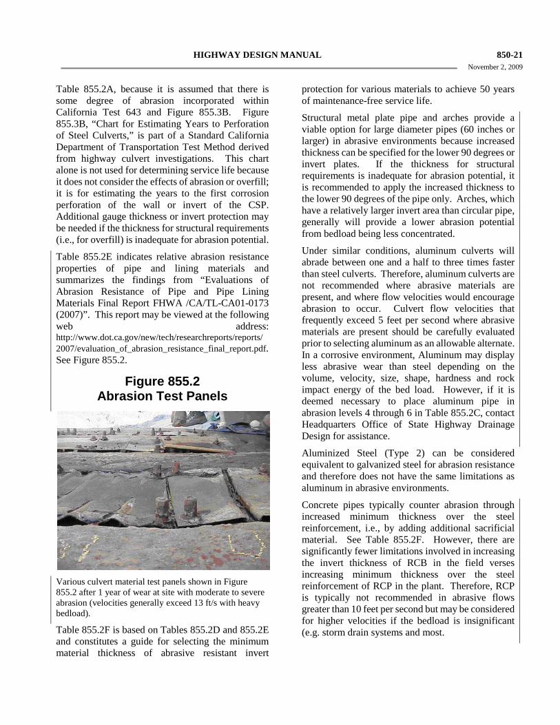
Table 855.2E indicates relative abrasion resistance properties of pipe and lining materials and summarizes the findings from “Evaluations of Abrasion Resistance of Pipe and Pipe Lining Materials Final Report FHWA /CA/TL-CA01-0173 (2007)”. This report may be viewed at the following web address: http://www.dot.ca.gov/new/tech/researchreports/reports/ 2007/evaluation_of_abrasion_resistance_final_report.pdf. See Figure 855.2.
Figure 855.2 Abrasion Test Panels
Various culvert material test panels shown in Figure 855.2 after 1 year of wear at site with moderate to severe abrasion (velocities generally exceed 13 ft/s with heavy bedload).
Table 855.2F is based on Tables 855.2D and 855.2E and constitutes a guide for selecting the minimum material thickness of abrasive resistant invert
protection for various materials to achieve 50 years of maintenance-free service life.
Structural metal plate pipe and arches provide a viable option for large diameter pipes (60 inches or larger) in abrasive environments because increased thickness can be specified for the lower 90 degrees or invert plates. If the thickness for structural requirements is inadequate for abrasion potential, it is recommended to apply the increased thickness to the lower 90 degrees of the pipe only. Arches, which have a relatively larger invert area than circular pipe, generally will provide a lower abrasion potential from bedload being less concentrated.
Under similar conditions, aluminum culverts will abrade between one and a half to three times faster than steel culverts. Therefore, aluminum culverts are not recommended where abrasive materials are present, and where flow velocities would encourage abrasion to occur. Culvert flow velocities that frequently exceed 5 feet per second where abrasive materials are present should be carefully evaluated prior to selecting aluminum as an allowable alternate. In a corrosive environment, Aluminum may display less abrasive wear than steel depending on the volume, velocity, size, shape, hardness and rock impact energy of the bed load. However, if it is deemed necessary to place aluminum pipe in abrasion levels 4 through 6 in Table 855.2C, contact Headquarters Office of State Highway Drainage Design for assistance.
Aluminized Steel (Type 2) can be considered equivalent to galvanized steel for abrasion resistance and therefore does not have the same limitations as aluminum in abrasive environments.
Concrete pipes typically counter abrasion through increased minimum thickness over the steel reinforcement, i.e., by adding additional sacrificial material. See Table 855.2F. However, there are significantly fewer limitations involved in increasing the invert thickness of RCB in the field verses increasing minimum thickness over the steel reinforcement of RCP in the plant. Therefore, RCP is typically not recommended in abrasive flows greater than 10 feet per second but may be considered for higher velocities if the bedload is insignificant (e.g. storm drain systems and most.
850-22 HIGHWAY DESIGN MANUAL March 7, 2014
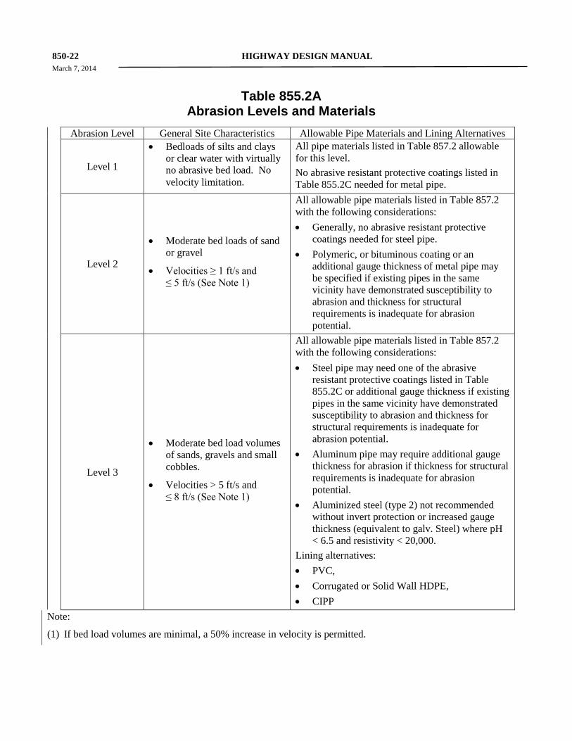
Table 855.2A Abrasion Levels and Materials
Abrasion Level General Site Characteristics Allowable Pipe Materials and Lining Alternatives
Level 1
• Bedloads of silts and clays or clear water with virtually no abrasive bed load. No velocity limitation.
All pipe materials listed in Table 857.2 allowable for this level. No abrasive resistant protective coatings listed in Table 855.2C needed for metal pipe.
Level 2
• Moderate bed loads of sand or gravel
• Velocities ≥ 1 ft/s and ≤ 5 ft/s (See Note 1)
All allowable pipe materials listed in Table 857.2 with the following considerations: • Generally, no abrasive resistant protective
coatings needed for steel pipe. • Polymeric, or bituminous coating or an
additional gauge thickness of metal pipe may be specified if existing pipes in the same vicinity have demonstrated susceptibility to abrasion and thickness for structural requirements is inadequate for abrasion potential.
Level 3
• Moderate bed load volumes of sands, gravels and small cobbles.
• Velocities > 5 ft/s and ≤ 8 ft/s (See Note 1)
All allowable pipe materials listed in Table 857.2 with the following considerations: • Steel pipe may need one of the abrasive
resistant protective coatings listed in Table 855.2C or additional gauge thickness if existing pipes in the same vicinity have demonstrated susceptibility to abrasion and thickness for structural requirements is inadequate for abrasion potential.
• Aluminum pipe may require additional gauge thickness for abrasion if thickness for structural requirements is inadequate for abrasion potential.
• Aluminized steel (type 2) not recommended without invert protection or increased gauge thickness (equivalent to galv. Steel) where pH < 6.5 and resistivity < 20,000.
Lining alternatives: • PVC, • Corrugated or Solid Wall HDPE, • CIPP
Note:
(1) If bed load volumes are minimal, a 50% increase in velocity is permitted.
HIGHWAY DESIGN MANUAL 850-23 March 7, 2014
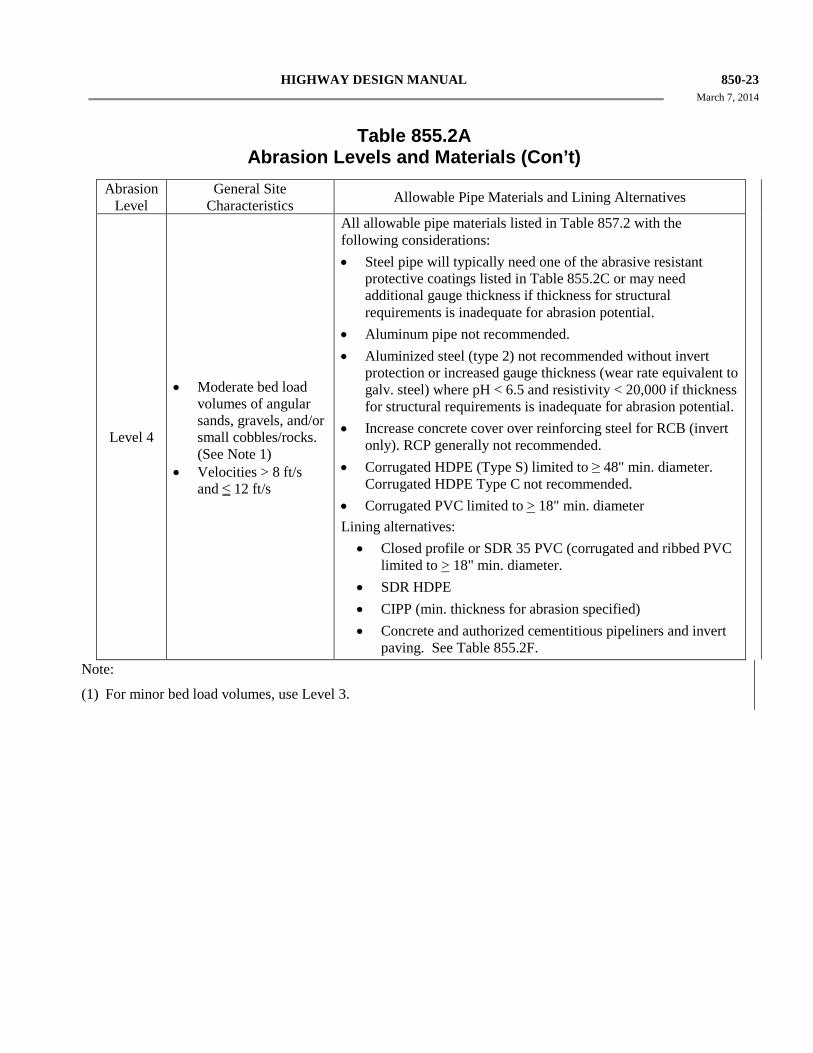
Table 855.2A Abrasion Levels and Materials (Con’t)
Abrasion Level
General Site Characteristics Allowable Pipe Materials and Lining Alternatives
Level 4
• Moderate bed load volumes of angular sands, gravels, and/or small cobbles/rocks. (See Note 1)
• Velocities > 8 ft/s and ≤ 12 ft/s
All allowable pipe materials listed in Table 857.2 with the following considerations: • Steel pipe will typically need one of the abrasive resistant
protective coatings listed in Table 855.2C or may need additional gauge thickness if thickness for structural requirements is inadequate for abrasion potential.
• Aluminum pipe not recommended. • Aluminized steel (type 2) not recommended without invert
protection or increased gauge thickness (wear rate equivalent to galv. steel) where pH < 6.5 and resistivity < 20,000 if thickness for structural requirements is inadequate for abrasion potential.
• Increase concrete cover over reinforcing steel for RCB (invert only). RCP generally not recommended.
• Corrugated HDPE (Type S) limited to ≥ 48" min. diameter. Corrugated HDPE Type C not recommended.
• Corrugated PVC limited to > 18" min. diameter Lining alternatives: • Closed profile or SDR 35 PVC (corrugated and ribbed PVC
limited to > 18" min. diameter. • SDR HDPE • CIPP (min. thickness for abrasion specified) • Concrete and authorized cementitious pipeliners and invert
paving. See Table 855.2F.
Note:
(1) For minor bed load volumes, use Level 3.
850-24 HIGHWAY DESIGN MANUAL March 7, 2014
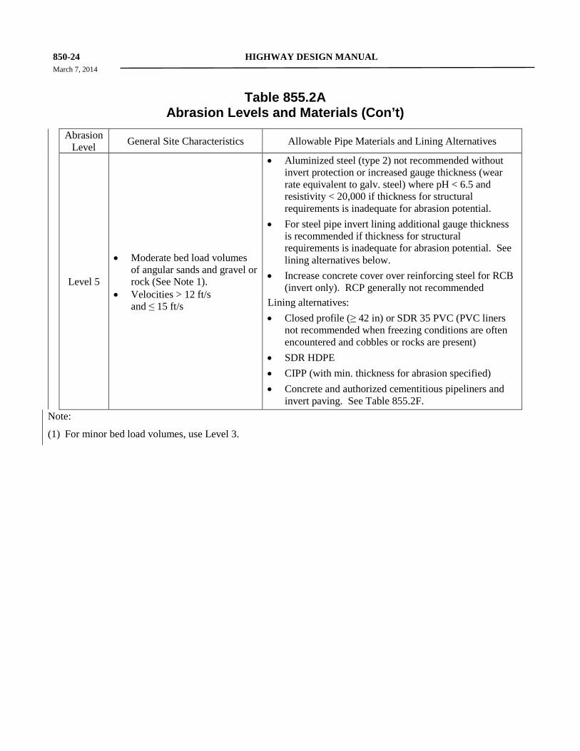
Table 855.2A Abrasion Levels and Materials (Con’t)
Abrasion Level General Site Characteristics Allowable Pipe Materials and Lining Alternatives
Level 5
• Moderate bed load volumes of angular sands and gravel or rock (See Note 1).
• Velocities > 12 ft/s and ≤ 15 ft/s
• Aluminized steel (type 2) not recommended without invert protection or increased gauge thickness (wear rate equivalent to galv. steel) where pH < 6.5 and resistivity < 20,000 if thickness for structural requirements is inadequate for abrasion potential.
• For steel pipe invert lining additional gauge thickness is recommended if thickness for structural requirements is inadequate for abrasion potential. See lining alternatives below.
• Increase concrete cover over reinforcing steel for RCB (invert only). RCP generally not recommended
Lining alternatives: • Closed profile (≥ 42 in) or SDR 35 PVC (PVC liners
not recommended when freezing conditions are often encountered and cobbles or rocks are present)
• SDR HDPE • CIPP (with min. thickness for abrasion specified) • Concrete and authorized cementitious pipeliners and
invert paving. See Table 855.2F.
Note:
(1) For minor bed load volumes, use Level 3.
HIGHWAY DESIGN MANUAL 850-25 March 7, 2014
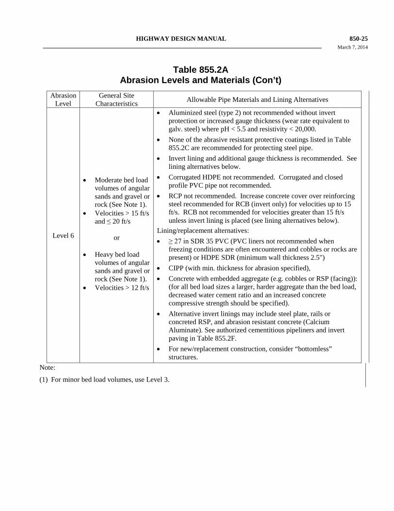
Table 855.2A Abrasion Levels and Materials (Con’t)
Abrasion Level
General Site Characteristics Allowable Pipe Materials and Lining Alternatives
Level 6
• Moderate bed load volumes of angular sands and gravel or rock (See Note 1).
• Velocities > 15 ft/s and ≤ 20 ft/s
or
• Heavy bed load
volumes of angular sands and gravel or rock (See Note 1).
• Velocities > 12 ft/s
• Aluminized steel (type 2) not recommended without invert protection or increased gauge thickness (wear rate equivalent to galv. steel) where pH < 5.5 and resistivity < 20,000.
• None of the abrasive resistant protective coatings listed in Table 855.2C are recommended for protecting steel pipe.
• Invert lining and additional gauge thickness is recommended. See lining alternatives below.
• Corrugated HDPE not recommended. Corrugated and closed profile PVC pipe not recommended.
• RCP not recommended. Increase concrete cover over reinforcing steel recommended for RCB (invert only) for velocities up to 15 ft/s. RCB not recommended for velocities greater than 15 ft/s unless invert lining is placed (see lining alternatives below).
Lining/replacement alternatives: • ≥ 27 in SDR 35 PVC (PVC liners not recommended when
freezing conditions are often encountered and cobbles or rocks are present) or HDPE SDR (minimum wall thickness 2.5")
• CIPP (with min. thickness for abrasion specified), • Concrete with embedded aggregate (e.g. cobbles or RSP (facing)):
(for all bed load sizes a larger, harder aggregate than the bed load, decreased water cement ratio and an increased concrete compressive strength should be specified).
• Alternative invert linings may include steel plate, rails or concreted RSP, and abrasion resistant concrete (Calcium Aluminate). See authorized cementitious pipeliners and invert paving in Table 855.2F.
• For new/replacement construction, consider “bottomless” structures.
Note:
(1) For minor bed load volumes, use Level 3.
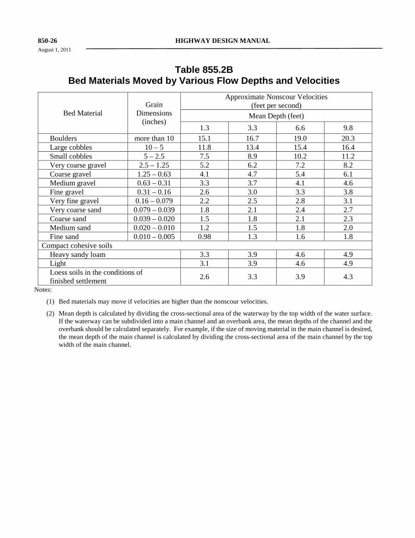
850-26 HIGHWAY DESIGN MANUAL August 1, 2011
Table 855.2B Bed Materials Moved by Various Flow Depths and Velocities
Bed Material Grain
Dimensions (inches)
Approximate Nonscour Velocities (feet per second)
Mean Depth (feet)
1.3 3.3 6.6 9.8 Boulders more than 10 15.1 16.7 19.0 20.3 Large cobbles 10 – 5 11.8 13.4 15.4 16.4 Small cobbles 5 – 2.5 7.5 8.9 10.2 11.2 Very coarse gravel 2.5 – 1.25 5.2 6.2 7.2 8.2 Coarse gravel 1.25 – 0.63 4.1 4.7 5.4 6.1 Medium gravel 0.63 – 0.31 3.3 3.7 4.1 4.6 Fine gravel 0.31 – 0.16 2.6 3.0 3.3 3.8 Very fine gravel 0.16 – 0.079 2.2 2.5 2.8 3.1 Very coarse sand 0.079 – 0.039 1.8 2.1 2.4 2.7 Coarse sand 0.039 – 0.020 1.5 1.8 2.1 2.3 Medium sand 0.020 – 0.010 1.2 1.5 1.8 2.0 Fine sand 0.010 – 0.005 0.98 1.3 1.6 1.8 Compact cohesive soils Heavy sandy loam 3.3 3.9 4.6 4.9 Light 3.1 3.9 4.6 4.9 Loess soils in the conditions of finished settlement 2.6 3.3 3.9 4.3
Notes:
(1) Bed materials may move if velocities are higher than the nonscour velocities.
(2) Mean depth is calculated by dividing the cross-sectional area of the waterway by the top width of the water surface. If the waterway can be subdivided into a main channel and an overbank area, the mean depths of the channel and the overbank should be calculated separately. For example, if the size of moving material in the main channel is desired, the mean depth of the main channel is calculated by dividing the cross-sectional area of the main channel by the top width of the main channel.
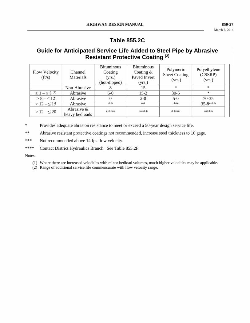
HIGHWAY DESIGN MANUAL 850-27 March 7, 2014
Table 855.2C
Guide for Anticipated Service Life Added to Steel Pipe by Abrasive Resistant Protective Coating (2)
Flow Velocity (ft/s)
Channel Materials
Bituminous Coating
(yrs.) (hot-dipped)
Bituminous Coating &
Paved Invert (yrs.)
Polymeric Sheet Coating
(yrs.)
Polyethylene (CSSRP)
(yrs.)
Non-Abrasive 8 15 * * ≥ 1 – ≤ 8 (1) Abrasive 6-0 15-2 30-5 * > 8 – ≤ 12 Abrasive 0 2-0 5-0 70-35 > 12 – ≤ 15 Abrasive ** ** ** 35-8***
> 12 – ≤ 20 Abrasive & heavy bedloads **** **** **** ****
* Provides adequate abrasion resistance to meet or exceed a 50-year design service life.
** Abrasive resistant protective coatings not recommended, increase steel thickness to 10 gage.
*** Not recommended above 14 fps flow velocity.
**** Contact District Hydraulics Branch. See Table 855.2F. Notes:
(1) Where there are increased velocities with minor bedload volumes, much higher velocities may be applicable. (2) Range of additional service life commensurate with flow velocity range.
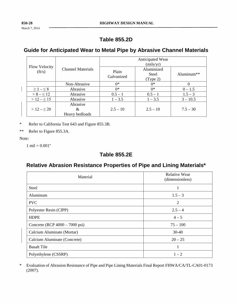
850-28 HIGHWAY DESIGN MANUAL March 7, 2014
Table 855.2D
Guide for Anticipated Wear to Metal Pipe by Abrasive Channel Materials
Flow Velocity (ft/s) Channel Materials
Anticipated Wear (mils/yr)
Plain Galvanized
Aluminized Steel
(Type 2) Aluminum**
Non-Abrasive 0* 0* 0 ≥ 1 – ≤ 8 Abrasive 0* 0* 0 – 1.5 > 8 – ≤ 12 Abrasive 0.5 – 1 0.5 – 1 1.5 – 3 > 12 – ≤ 15 Abrasive 1 – 3.5 1 – 3.5 3 – 10.5
> 12 – ≤ 20 Abrasive
& Heavy bedloads
2.5 – 10 2.5 – 10 7.5 – 30
* Refer to California Test 643 and Figure 855.3B.
** Refer to Figure 855.3A.
Note:
1 mil = 0.001"
Table 855.2E
Relative Abrasion Resistance Properties of Pipe and Lining Materials* Material Relative Wear
(dimensionless)
Steel 1
Aluminum 1.5 – 3
PVC 2
Polyester Resin (CIPP) 2.5 – 4
HDPE 4 – 5
Concrete (RCP 4000 – 7000 psi) 75 – 100
Calcium Aluminate (Mortar) 30-40
Calcium Aluminate (Concrete) 20 – 25
Basalt Tile 1
Polyethylene (CSSRP) 1 – 2 * Evaluation of Abrasion Resistance of Pipe and Pipe Lining Materials Final Report FHWA/CA/TL-CA01-0173
(2007).
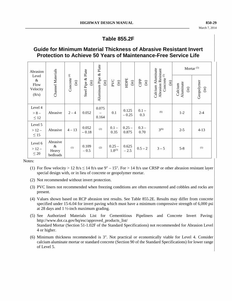
HIGHWAY DESIGN MANUAL 850-29 March 7, 2014
Table 855.2F
Guide for Minimum Material Thickness of Abrasive Resistant Invert Protection to Achieve 50 Years of Maintenance-Free Service Life
Abrasion
Level &
Flow Velocity
(ft/s) Cha
nnel
Mat
eria
ls
Con
cret
e (4
) (in
)
Stee
l Pip
e &
Pla
te
(in)
Alu
min
um P
ipe
& P
late
(in
)
PVC
(in
)
HD
PE
(in)
CIP
P (in
)
Cal
cium
Alu
min
ate
Abr
asio
n R
esis
tant
C
oncr
ete
(5)
(in)
Mortar (5)
Cal
cium
A
lum
inat
e (in
)
Geo
poly
mer
(in
)
Level 4 > 8 – ≤ 12
Abrasive 2 – 4 0.052 0.075
– 0.164
0.1 0.125 – 0.25
0.1 – 0.3
(6) 1-2 2-4
Level 5 > 12 – ≤ 15
Abrasive 4 – 13 0.052 – 0.18
(2) 0.1 – 0.35
0.25 – 0.875
0.3 – 0.70 3(6) 2-5 4-13
Level 6 > 12 – ≤ 20
Abrasive &
Heavy bedloads
(1) 0.109 – 0.5
(2) 0.25 – 1.0(3)
0.625 – 2.5 0.5 – 2 3 – 5 5-8 (1)
Notes:
(1) For flow velocity > 12 ft/s ≤ 14 ft/s use 9" – 15". For > 14 ft/s use CRSP or other abrasion resistant layer special design with, or in lieu of concrete or geopolymer mortar.
(2) Not recommended without invert protection.
(3) PVC liners not recommended when freezing conditions are often encountered and cobbles and rocks are present.
(4) Values shown based on RCP abrasion test results. See Table 855.2E. Results may differ from concrete specified under 15-6.04 for invert paving which must have a minimum compressive strength of 6,000 psi at 28 days and 1 ½-inch maximum grading.
(5) See Authorized Materials List for Cementitious Pipeliners and Concrete Invert Paving: http://www.dot.ca.gov/hq/esc/approved_products_list/ Standard Mortar (Section 51-1.02F of the Standard Specifications) not recommended for Abrasion Level 4 or higher.
(6) Minimum thickness recommended is 3". Not practical or economically viable for Level 4. Consider calcium aluminate mortar or standard concrete (Section 90 of the Standard Specifications) for lower range of Level 5.
850-30 HIGHWAY DESIGN MANUAL December 30, 2015
culverts smaller than 30 inches or larger diameters with insignificant abrasive bedload volumes).
Abrasion resistance for any concrete lining is dependent upon the thickness, quality, strength, and hardness of the aggregate and compressive strength of the concrete as well as the velocity of the water flow coupled with abrasive sediment content and acidity. Abrasion resistant concrete or mortar made from calcium aluminate provides much improved abrasion resistance over cementitious concrete and should be considered as a viable countermeasure in extremely abrasive conditions (i.e, velocity greater than 15 feet per second with heavy bedload). See Table 855.2F.
Plastic materials typically exhibit good abrasion resistance but service life is constrained by the manufactured thickness of typical pipe profiles. Both PVC and HDPE corrugated pipe are limited for their use in moderate and heavy bedload abrasion conditions by the combined manufactured inner liner and corrugated wall thicknesses. For culvert rehabilitation, PVC and HDPE pipe slip lining products (e.g. solid wall HDPE) are viable options for applications in moderate and heavy bedload abrasion conditions (see Table 855.2A).
Table 855.2A can be used as a “preliminary estimator” of abrasion potential for material selection to achieve the required service life, however, it incorporates only three of the primary abrasion factors; bedload volume, bedload type and flow velocity and the general assumption is the materials are angular, hard and abrasive. As discussed above, the other factors that are not used in the table should also be carefully considered. For example, under similar hydraulic conditions, heavy volumes of hard, angular sand may be more abrasive than small volumes of relatively soft, large or rounded rocks. Furthermore, two sites with similar site characteristics, but different hydrologic characteristics, i.e., volume, duration and frequency of stream flow in the culvert, will likely also have different abrasion levels. Table 855.2B can be used as a guide with Table 855.2A to determine the maximum size of material that can be moved through a pipe. Field observations of channel bed material both upstream and downstream from the pipe are extremely important for estimating the size range of transportable material in the channel.
855.3 Corrosion Corrosion is the destructive attack on a pipe by a chemical reaction with the materials surrounding the pipe. Corrosion problems can occur when metal pipes are used in locations where the surrounding materials have excess acidity or alkalinity. The relative acidity of a substance is often expressed by its pH value. The pH scale ranges from 1 to 14, with 1 representing extreme acidity, and 14 representing extreme alkalinity, and 7 representing a neutral substance. The closer the pH value is to 7, the less potential the substance has for causing corrosion.
Corrosion is an electrolytic process and requires an electrolyte (generally moisture) and oxygen to proceed. As a result, it has the greatest potential for causing damage in soils that have a relative high ability to pass electric current. The ability of a soil to convey current is expressed as its resistivity in ohm-cm, and a soil with a low resistivity has a greater ability to conduct electricity. Very dry areas (e.g., desert environments) have a limited availability of electrolyte, and totally and continuously submerged pipes have limited oxygen availability. These extreme conditions (among others) are not well represented by AltPipe, and some adjustment in the estimated service life for pipes in these conditions should be made. See Index 857.2
Corrosion can also be caused by excessive acidity in the water conveyed by the pipe. Water pH can vary considerably between watersheds and seasons.
Because failure can occur at any point along the length of the pipe (e.g. tidal zones), the designer must look at the conditions and how they may vary along the pipe length - and select for input into AltPipe those conditions that represent the most severe situation along the length.
AltPipe operates based on some fairly basic assumptions for corrosion and minimum resistivity that are part of California Test 643. Altpipe will list all viable alternatives for achieving design service life. Where enhanced soilside corrosion protection is needed, aluminum or aluminized pipe (if within acceptable pH/min. resistivity ranges), bituminous coatings or polymeric sheet coating should be considered.
HIGHWAY DESIGN MANUAL 850-31 March 7, 2014
Aluminum, and the aluminum coating provided by Aluminized Steel (Type 2) pipe, corrodes differently than steel and will provide adequate durability to meet the 50-year service life criterion within the acceptable pH range of 5.5-8.5 and minimum resistivity greater than 1500 ohm-cm without need for specifying a thicker gauge or additional coating, whereas under the same range galvanized steel may need a protective coating or an increase in thickness to provide a 50-year maintenance-free service life (with respect to corrosion). Figure 855.3A should be used to determine the limitations on the use of corrugated aluminum pipe for various levels of pH and minimum resistivity. The minimum thickness (0.060 inch) of aluminum pipe obtained from the chart only satisfies corrosion requirements. Overfill requirements for minimum metal thickness must also be satisfied. The metal thickness of corrugated aluminum pipe should satisfy both requirements.
Figure 855.3A should be used to determine the minimum thickness and limitation on the use of corrugated steel and spiral rib pipe for various levels of pH and minimum resistivity. For example, given a soil environment with pH and minimum resistivity levels of 6.5 and 15,000 ohm-cm, respectively, the minimum thicknesses for the various metal pipes are: 1) 0.109 inch (12 gage) galvanized steel, 2) 0.064 inch (16 gage) aluminized steel (type 2) and 3) 0.060 inch (16 gage) aluminum. The minimum thickness of metal pipe obtained from the figure only satisfies corrosion requirements. Overfill requirements for minimum metal thickness must also be satisfied. The metal thickness of corrugated pipe and steel spiral rib pipe that satisfies both requirements should be used.
Figure 855.3B, “Chart for Estimating Years to Perforation of Steel Culverts,” is part of a Standard California Department of Transportation Test Method derived from highway culvert investigations. This chart alone is not used for determining service life because it does not consider the effects of abrasion or overfill; it is for estimating the years to the first corrosion perforation of the wall or invert of the CSP.
855.4 Protection of Concrete Pipe and Drainage Structures from Acids, Chlorides and Sulfates Table 855.4A indicates the limitation on the use of concrete by acidity of soil and water. Table 855.4A is also a guide for designating cementitious material restrictions and water content restrictions for various ranges of sulfate concentrations in soil and water for all cast in place and precast construction of drainage structures.
For pH ranging between 7.0 and 3.0 and for sulfate concentrations between 1500 and 15,000 ppm, concrete mix designs conforming to the recommendations given in Table 855.4A should be followed. Higher sulfate concentrations or lower pH values may preclude the use of concrete or would require the designer to develop and specify the application of a complete physical barrier. Reinforcing steel can be expected to respond to corrosive environments similarly to the steel in CSP.
Table 855.4B provides a guide for minimum concrete cover requirements for various ranges of chloride concentrations in soil and water for all precast and cast in place construction of drainage structures.
(1) RCP. In relatively severe acidic, chloride or sulfate environments (either in the soil or water) as identified in the project Materials Report, the means for offsetting the effects of the corrosive elements is to either increase the cover over the reinforcing steel, increase the cementitious material content, or reduce the water/ cementitious material ratio. The identified constituent concentration levels should be entered into AltPipe to verify what combinations of increased cover (in 1/4-inch intervals from 1 inch to a maximum of 1-1/2 inches), increased cementitious material content (in increments of 47 pounds from 470 pounds to a maximum of 564 pounds), will provide the necessary service life (typically 50 years). Per an agreement with Industry, the water to cementitious material ratio is set at 0.40. AltPipe is specifically programmed to provide RCP mix and cover designs that are compatible with industry practice, and are based on their agreements with Caltrans. For corrosive condition installations such as low pH (<4.5),
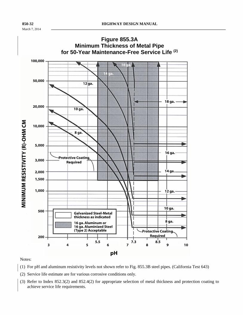
850-32 HIGHWAY DESIGN MANUAL March 7, 2014
Figure 855.3A
Minimum Thickness of Metal Pipe for 50-Year Maintenance-Free Service Life (2)
Notes:
(1) For pH and aluminum resistivity levels not shown refer to Fig. 855.3B steel pipes. (California Test 643)
(2) Service life estimate are for various corrosive conditions only.
(3) Refer to Index 852.3(2) and 852.4(2) for appropriate selection of metal thickness and protection coating to achieve service life requirements.
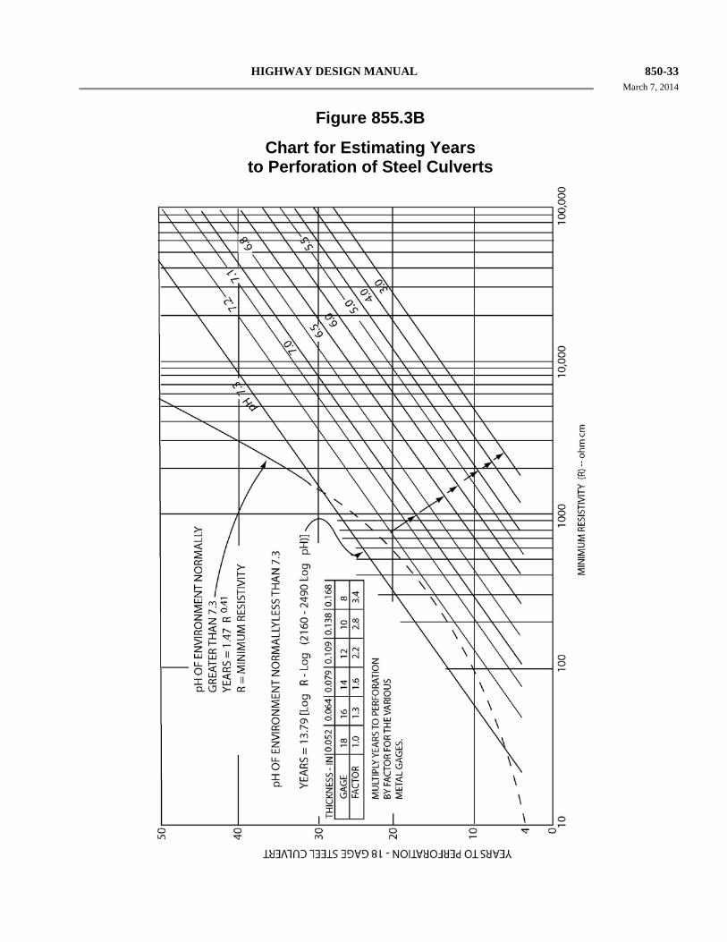
HIGHWAY DESIGN MANUAL 850-33 March 7, 2014
Figure 855.3B
Chart for Estimating Years to Perforation of Steel Culverts
850-34 HIGHWAY DESIGN MANUAL December 30, 2015
Chlorides (>2,000 ppm) or Sulfates
(> 2,000 ppm), the following service life (SL) equation provides the basis for RCP design in AltPipe:
( )
4.41S102.94pH104.22W
1KDcCc1.10710SL314.1100.631
0.371.220.717Cc3
+××−××−×
+××××=−−−
−
Where: S = Environmental sulfate content in ppm.
Cc = Sacks of cement (94 lbs each) per cubic yard of concrete.
Dc = Concrete cover in inches.
K = Environmental chloride concentration in ppm.
W = Water by volume as percentage of total mix.
pH = The measure of relative acidity or alkalinity of the soil or water. See Index 855.3.
Where the measured concentration of chlorides exceeds 2000 ppm for RCP that is placed in brackish or marine environments and where the high tide line is below the crown of the invert, the AltPipe input for chloride concentration will default to 25,000 ppm.
Contact the District Materials unit or the Corrosion Technology Branch in DES for design recommendations when in extremely corrosive conditions. Non-Reinforced concrete pipe is not affected by chlorides or stray currents and may be used in lieu of RCP with additional concrete cover and/or protective coatings for sizes 36" in diameter and smaller. See Index 852.1(4) and Table 855.4A. Where conditions occur that RCP designs as produced by AltPipe will not work, the Office of State Highway Drainage Design within the Division of Design should be contacted.
855.5 Material Susceptibility to Fire Fire can occur almost anywhere on the highway system. Common causes include forest, brush or grass fires that either enter the right-of-way or begin within it. Less common causes include spills of flammable liquids that ignite or vandalism. Storm drains, which are completely buried would typically
be impacted by spills or vandalism. Because these are such low probability events, prohibitions on material placement for storm drains are not typically warranted.
Cross culverts and exposed overside drains are the placement types most subject to burning or melting and designers should consider either limiting the alternative pipe listing to non-flammable pipe materials or providing a non-flammable end treatment to provide some level of protection.
Plastic pipe and pipes with coatings (typically of bituminous or plastic materials) are the most susceptible to damage from fire. Of the plastic pipe types which are allowed, PVC will self extinguish if the source of the fire is eliminated (i.e., if the grass or brush is consumed or removed) while HDPE can continue to burn as long as an adequate oxygen supply is present. Based on testing performed by Florida DOT, this rate of burning is fairly slow, and often self extinguished if the airflow was inhibited (i.e., pipe not aligned with prevailing wind or ends sheltered from air flow).
Due to the potential for fire damage, plastic pipe is not recommended for overside drain locations where there is high fire potential (large amounts of brush or grass or areas with a history of fire) and where the overside drain is placed or anchored on top of the slope.
Where similar high fire potential conditions exist for cross culverts, the designer may consider limiting the allowable pipe materials indicated on the alternative pipe listing to non-flammable material types, use concrete endwalls that eliminate exposure of the pipe ends, or require that the end of flammable pipe types be replaced with a length of non-flammable pipe material.
Topic 856 - Height of Fill An essential aspect of pipe selection is the height of fill/cover over the pipe. This cover dissipates live loads from traffic, both during construction and after the facility is open to the public.
856.1 Construction Loads
See Standard Plan D88 for table of minimum cover for construction loads.
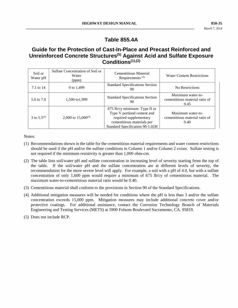
HIGHWAY DESIGN MANUAL 850-35 March 7, 2014
Table 855.4A
Guide for the Protection of Cast-In-Place and Precast Reinforced and Unreinforced Concrete Structures(5) Against Acid and Sulfate Exposure
Conditions(1),(2)
Soil or Water pH
Sulfate Concentration of Soil or Water (ppm)
Cementitious Material Requirements (3) Water Content Restrictions
7.1 to 14 0 to 1,499
Standard Specifications Section 90 No Restrictions
5.6 to 7.0 1,500 to1,999 Standard Specifications Section
90
Maximum water-to-cementitious material ratio of
0.45
3 to 5.5(4) 2,000 to 15,000(4)
675 lb/cy minimum: Type II or Type V portland cement and
required supplementary cementitious materials per
Standard Specification 90-1.02H
Maximum water-to-cementitious material ratio of
0.40
Notes:
(1) Recommendations shown in the table for the cementitious material requirements and water content restrictions should be used if the pH and/or the sulfate conditions in Column 1 and/or Column 2 exists. Sulfate testing is not required if the minimum resistivity is greater than 1,000 ohm-cm.
(2) The table lists soil/water pH and sulfate concentration in increasing level of severity starting from the top of the table. If the soil/water pH and the sulfate concentration are at different levels of severity, the recommendation for the more severe level will apply. For example, a soil with a pH of 4.0, but with a sulfate concentration of only 1,600 ppm would require a minimum of 675 lb/cy of cementitious material. The maximum water-to-cementitious material ratio would be 0.40.
(3) Cementitious material shall conform to the provisions in Section 90 of the Standard Specifications.
(4) Additional mitigation measures will be needed for conditions where the pH is less than 3 and/or the sulfate concentration exceeds 15,000 ppm. Mitigation measures may include additional concrete cover and/or protective coatings. For additional assistance, contact the Corrosion Technology Branch of Materials Engineering and Testing Services (METS) at 5900 Folsom Boulevard Sacramento, CA. 95819.
(5) Does not include RCP.
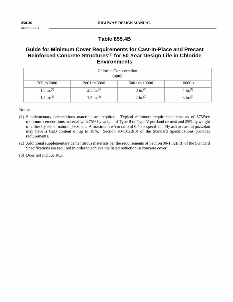
850-36 HIGHWAY DESIGN MANUAL March 7, 2014
Table 855.4B
Guide for Minimum Cover Requirements for Cast-In-Place and Precast Reinforced Concrete Structures(3) for 50-Year Design Life in Chloride
Environments Chloride Concentration
(ppm)
500 to 2000 2001 to 5000 5001 to 10000 10000 +
1.5 in.(1) 2.5 in.(1) 3 in.(1) 4 in.(1)
1.5 in.(2) 1.5 in.(2) 2 in.(2) 3 in.(2)
Notes:
(1) Supplementary cementitious materials are required. Typical minimum requirement consists of 675#/cy minimum cementitious material with 75% by weight of Type II or Type V portland cement and 25% by weight of either fly ash or natural pozzolan. A maximum w/cm ratio of 0.40 is specified. Fly ash or natural pozzolan may have a CaO content of up to 10%. Section 90-1.02B(3) of the Standard Specifications provides requirements.
(2) Additional supplementary cementitious materials per the requirements of Section 90-1.02B(3) of the Standard Specifications are required in order to achieve the listed reduction in concrete cover.
(3) Does not include RCP.
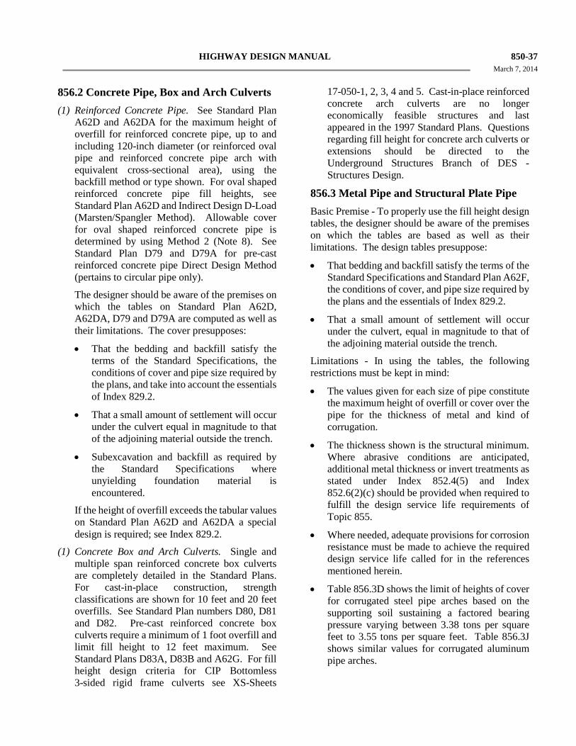
HIGHWAY DESIGN MANUAL 850-37 March 7, 2014
856.2 Concrete Pipe, Box and Arch Culverts (1) Reinforced Concrete Pipe. See Standard Plan
A62D and A62DA for the maximum height of overfill for reinforced concrete pipe, up to and including 120-inch diameter (or reinforced oval pipe and reinforced concrete pipe arch with equivalent cross-sectional area), using the backfill method or type shown. For oval shaped reinforced concrete pipe fill heights, see Standard Plan A62D and Indirect Design D-Load (Marsten/Spangler Method). Allowable cover for oval shaped reinforced concrete pipe is determined by using Method 2 (Note 8). See Standard Plan D79 and D79A for pre-cast reinforced concrete pipe Direct Design Method (pertains to circular pipe only).
The designer should be aware of the premises on which the tables on Standard Plan A62D, A62DA, D79 and D79A are computed as well as their limitations. The cover presupposes:
• That the bedding and backfill satisfy the terms of the Standard Specifications, the conditions of cover and pipe size required by the plans, and take into account the essentials of Index 829.2.
• That a small amount of settlement will occur under the culvert equal in magnitude to that of the adjoining material outside the trench.
• Subexcavation and backfill as required by the Standard Specifications where unyielding foundation material is encountered.
If the height of overfill exceeds the tabular values on Standard Plan A62D and A62DA a special design is required; see Index 829.2.
(1) Concrete Box and Arch Culverts. Single and multiple span reinforced concrete box culverts are completely detailed in the Standard Plans. For cast-in-place construction, strength classifications are shown for 10 feet and 20 feet overfills. See Standard Plan numbers D80, D81 and D82. Pre-cast reinforced concrete box culverts require a minimum of 1 foot overfill and limit fill height to 12 feet maximum. See Standard Plans D83A, D83B and A62G. For fill height design criteria for CIP Bottomless 3-sided rigid frame culverts see XS-Sheets
17-050-1, 2, 3, 4 and 5. Cast-in-place reinforced concrete arch culverts are no longer economically feasible structures and last appeared in the 1997 Standard Plans. Questions regarding fill height for concrete arch culverts or extensions should be directed to the Underground Structures Branch of DES - Structures Design.
856.3 Metal Pipe and Structural Plate Pipe Basic Premise - To properly use the fill height design tables, the designer should be aware of the premises on which the tables are based as well as their limitations. The design tables presuppose:
• That bedding and backfill satisfy the terms of the Standard Specifications and Standard Plan A62F, the conditions of cover, and pipe size required by the plans and the essentials of Index 829.2.
• That a small amount of settlement will occur under the culvert, equal in magnitude to that of the adjoining material outside the trench.
Limitations - In using the tables, the following restrictions must be kept in mind:
• The values given for each size of pipe constitute the maximum height of overfill or cover over the pipe for the thickness of metal and kind of corrugation.
• The thickness shown is the structural minimum. Where abrasive conditions are anticipated, additional metal thickness or invert treatments as stated under Index 852.4(5) and Index 852.6(2)(c) should be provided when required to fulfill the design service life requirements of Topic 855.
• Where needed, adequate provisions for corrosion resistance must be made to achieve the required design service life called for in the references mentioned herein.
• Table 856.3D shows the limit of heights of cover for corrugated steel pipe arches based on the supporting soil sustaining a factored bearing pressure varying between 3.38 tons per square feet to 3.55 tons per square feet. Table 856.3J shows similar values for corrugated aluminum pipe arches.
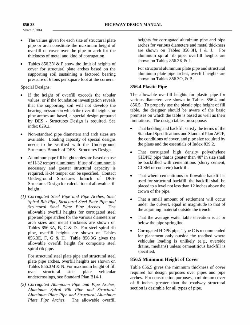
850-38 HIGHWAY DESIGN MANUAL March 7, 2014
• The values given for each size of structural plate
pipe or arch constitute the maximum height of overfill or cover over the pipe or arch for the thickness of metal and kind of corrugation.
• Tables 856.3N & P show the limit of heights of cover for structural plate arches based on the supporting soil sustaining a factored bearing pressure of 6 tons per square foot at the corners.
Special Designs.
• If the height of overfill exceeds the tabular values, or if the foundation investigation reveals that the supporting soil will not develop the bearing pressure on which the overfill heights for pipe arches are based, a special design prepared by DES - Structures Design is required. See index 829.2.
• Non-standard pipe diameters and arch sizes are available. Loading capacity of special designs needs to be verified with the Underground Structures Branch of DES - Structures Design.
• Aluminum pipe fill height tables are based on use of H-32 temper aluminum. If use of aluminum is necessary and greater structural capacity is required, H-34 temper can be specified. Contact Underground Structures branch of DES-Structures Design for calculation of allowable fill height.
(1) Corrugated Steel Pipe and Pipe Arches, Steel Spiral Rib Pipe, Structural Steel Plate Pipe and Structural Steel Plate Pipe Arches. The allowable overfill heights for corrugated steel pipe and pipe arches for the various diameters or arch sizes and metal thickness are shown on Tables 856.3A, B, C & D. For steel spiral rib pipe, overfill heights are shown on Tables 856.3E, F, G & H. Table 856.3G gives the allowable overfill height for composite steel spiral rib pipe.
For structural steel plate pipe and structural steel plate pipe arches, overfill heights are shown on Tables 856.3M & N. For maximum height of fill over structural steel plate vehicular undercrossings, see Standard Plan B14-1.
(2) Corrugated Aluminum Pipe and Pipe Arches, Aluminum Spiral Rib Pipe and Structural Aluminum Plate Pipe and Structural Aluminum Plate Pipe Arches. The allowable overfill
heights for corrugated aluminum pipe and pipe arches for various diameters and metal thickness are shown on Tables 856.3H, I & J. For aluminum spiral rib pipe, overfill heights are shown on Tables 856.3K & L.
For structural aluminum plate pipe and structural aluminum plate pipe arches, overfill heights are shown on Tables 856.3O, & P.
856.4 Plastic Pipe The allowable overfill heights for plastic pipe for various diameters are shown in Tables 856.4 and 856.5. To properly use the plastic pipe height of fill table, the designer should be aware of the basic premises on which the table is based as well as their limitations. The design tables presuppose:
• That bedding and backfill satisfy the terms of the Standard Specifications and Standard Plan A62F, the conditions of cover, and pipe size required by the plans and the essentials of Index 829.2.
• That corrugated high density polyethylene (HDPE) pipe that is greater than 48" in size shall be backfilled with cementitious (slurry cement, CLSM or concrete) backfill.
• That where cementitious or flowable backfill is used for structural backfill, the backfill shall be placed to a level not less than 12 inches above the crown of the pipe.
• That a small amount of settlement will occur under the culvert, equal in magnitude to that of the adjoining material outside the trench.
• That the average water table elevation is at or below the pipe springline.
• Corrugated HDPE pipe, Type C is recommended for placement only outside the roadbed where vehicular loading is unlikely (e.g., overside drains, medians) unless cementitious backfill is specified.
856.5 Minimum Height of Cover Table 856.5 gives the minimum thickness of cover required for design purposes over pipes and pipe arches. For construction purposes, a minimum cover of 6 inches greater than the roadway structural section is desirable for all types of pipe.
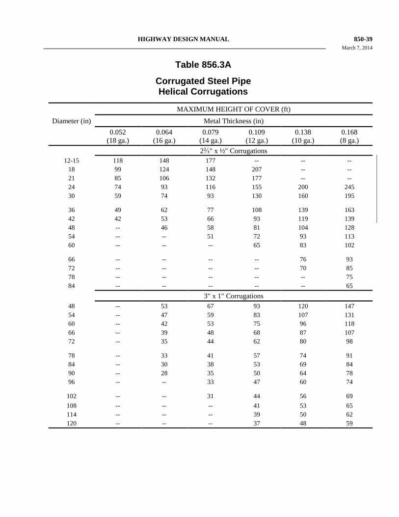
HIGHWAY DESIGN MANUAL 850-39 March 7, 2014
Table 856.3A
Corrugated Steel Pipe Helical Corrugations
MAXIMUM HEIGHT OF COVER (ft) Diameter (in) Metal Thickness (in) 0.052
(18 ga.) 0.064
(16 ga.) 0.079
(14 ga.) 0.109
(12 ga.) 0.138
(10 ga.) 0.168 (8 ga.)
2⅔" x ½" Corrugations 12-15 118 148 177 -- -- -- 18 99 124 148 207 -- -- 21 85 106 132 177 -- -- 24 74 93 116 155 200 245 30 59 74 93 130 160 195
36 49 62 77 108 139 163 42 42 53 66 93 119 139 48 -- 46 58 81 104 128 54 -- -- 51 72 93 113 60 -- -- -- 65 83 102
66 -- -- -- -- 76 93 72 -- -- -- -- 70 85 78 -- -- -- -- -- 75 84 -- -- -- -- -- 65 3" x 1" Corrugations 48 -- 53 67 93 120 147 54 -- 47 59 83 107 131 60 -- 42 53 75 96 118 66 -- 39 48 68 87 107 72 -- 35 44 62 80 98
78 -- 33 41 57 74 91 84 -- 30 38 53 69 84 90 -- 28 35 50 64 78 96 -- -- 33 47 60 74
102 -- -- 31 44 56 69 108 -- -- -- 41 53 65 114 -- -- -- 39 50 62 120 -- -- -- 37 48 59
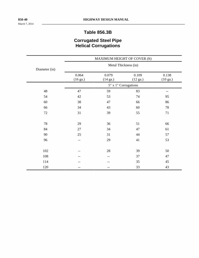
850-40 HIGHWAY DESIGN MANUAL March 7, 2014
Table 856.3B
Corrugated Steel Pipe Helical Corrugations
MAXIMUM HEIGHT OF COVER (ft)
Diameter (in) Metal Thickness (in)
0.064 (16 ga.)
0.079 (14 ga.)
0.109 (12 ga.)
0.138 (10 ga.)
5" x 1" Corrugations 48 47 59 83 -- 54 42 53 74 95 60 38 47 66 86 66 34 43 60 78 72 31 39 55 71 78 29 36 51 66 84 27 34 47 61 90 25 31 44 57 96 -- 29 41 53 102 -- 28 39 50 108 -- -- 37 47 114 -- -- 35 45 120 -- -- 33 43
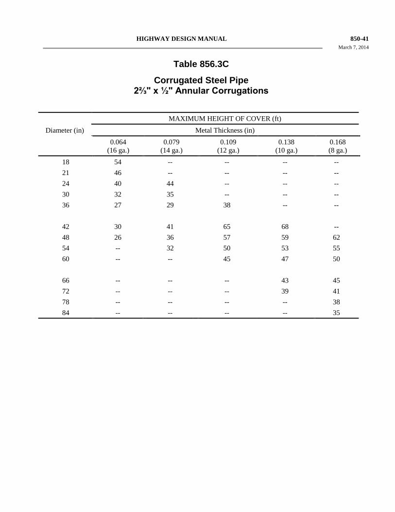
HIGHWAY DESIGN MANUAL 850-41 March 7, 2014
Table 856.3C
Corrugated Steel Pipe 2⅔" x ½" Annular Corrugations
MAXIMUM HEIGHT OF COVER (ft) Diameter (in) Metal Thickness (in)
0.064 (16 ga.)
0.079 (14 ga.)
0.109 (12 ga.)
0.138 (10 ga.)
0.168 (8 ga.)
18 54 -- -- -- -- 21 46 -- -- -- -- 24 40 44 -- -- -- 30 32 35 -- -- -- 36 27 29 38 -- --
42 30 41 65 68 -- 48 26 36 57 59 62 54 -- 32 50 53 55 60 -- -- 45 47 50
66 -- -- -- 43 45 72 -- -- -- 39 41 78 -- -- -- -- 38 84 -- -- -- -- 35
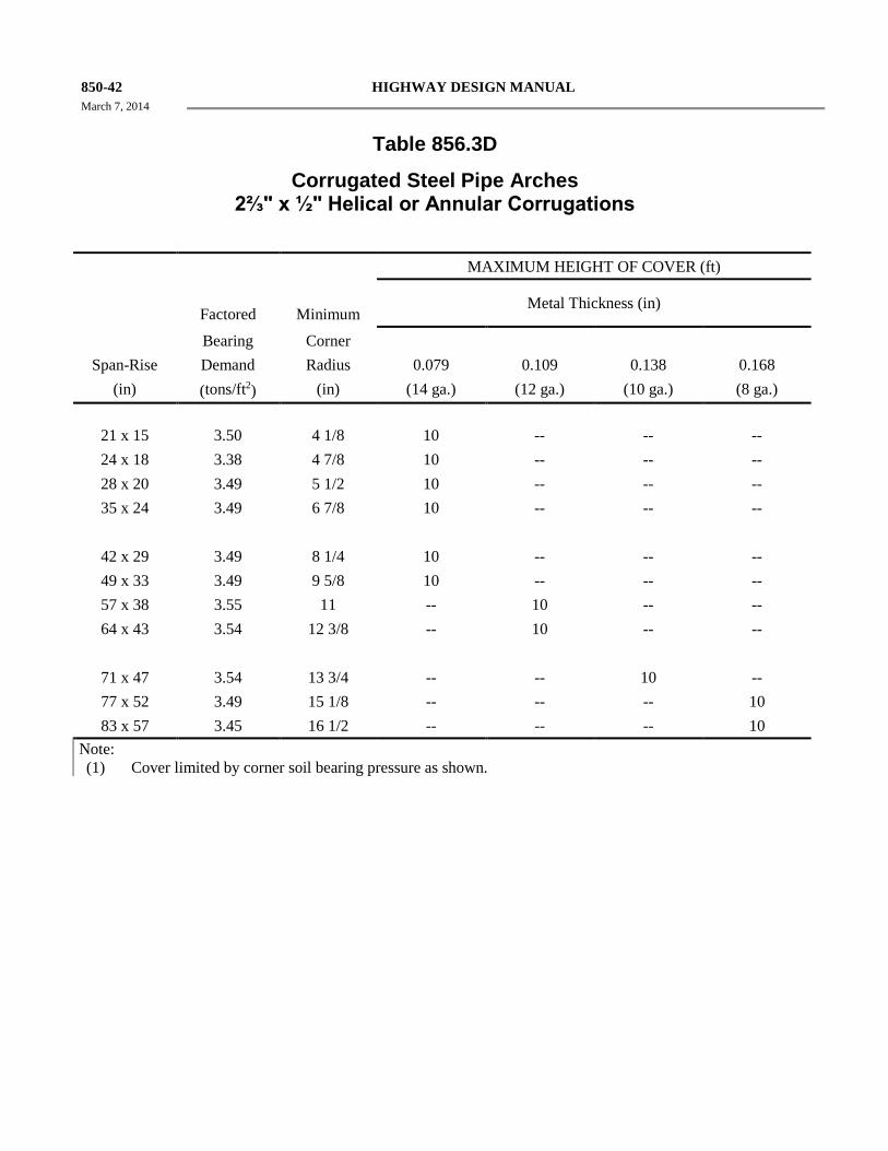
850-42 HIGHWAY DESIGN MANUAL March 7, 2014
Table 856.3D
Corrugated Steel Pipe Arches 2⅔" x ½" Helical or Annular Corrugations
MAXIMUM HEIGHT OF COVER (ft)
Factored
Minimum Metal Thickness (in)
Bearing Corner Span-Rise Demand Radius 0.079 0.109 0.138 0.168
(in) (tons/ft2) (in) (14 ga.) (12 ga.) (10 ga.) (8 ga.)
21 x 15 3.50 4 1/8 10 -- -- -- 24 x 18 3.38 4 7/8 10 -- -- -- 28 x 20 3.49 5 1/2 10 -- -- -- 35 x 24 3.49 6 7/8 10 -- -- --
42 x 29 3.49 8 1/4 10 -- -- -- 49 x 33 3.49 9 5/8 10 -- -- -- 57 x 38 3.55 11 -- 10 -- -- 64 x 43 3.54 12 3/8 -- 10 -- --
71 x 47 3.54 13 3/4 -- -- 10 -- 77 x 52 3.49 15 1/8 -- -- -- 10 83 x 57 3.45 16 1/2 -- -- -- 10
Note: (1) Cover limited by corner soil bearing pressure as shown.
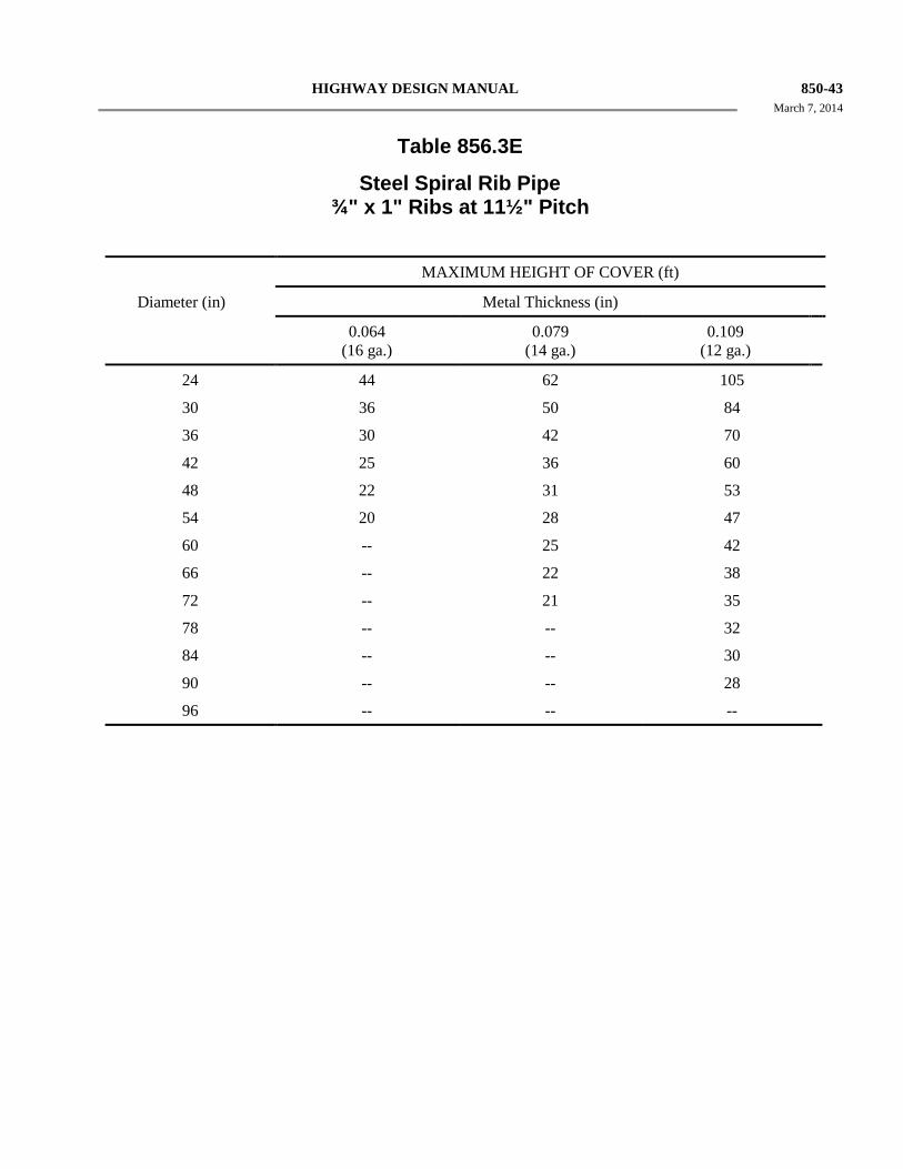
HIGHWAY DESIGN MANUAL 850-43 March 7, 2014
Table 856.3E
Steel Spiral Rib Pipe ¾" x 1" Ribs at 11½" Pitch
MAXIMUM HEIGHT OF COVER (ft)
Diameter (in) Metal Thickness (in)
0.064 (16 ga.)
0.079 (14 ga.)
0.109 (12 ga.)
24 44 62 105
30 36 50 84
36 30 42 70
42 25 36 60
48 22 31 53
54 20 28 47
60 -- 25 42
66 -- 22 38
72 -- 21 35
78 -- -- 32
84 -- -- 30
90 -- -- 28
96 -- -- --
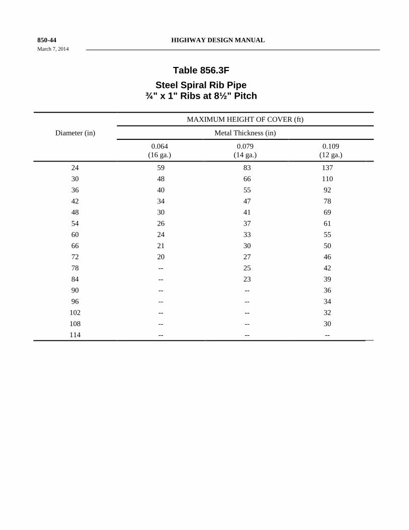
850-44 HIGHWAY DESIGN MANUAL March 7, 2014
Table 856.3F Steel Spiral Rib Pipe
¾" x 1" Ribs at 8½" Pitch
MAXIMUM HEIGHT OF COVER (ft)
Diameter (in) Metal Thickness (in)
0.064 (16 ga.)
0.079 (14 ga.)
0.109 (12 ga.)
24 59 83 137 30 48 66 110 36 40 55 92 42 34 47 78 48 30 41 69 54 26 37 61 60 24 33 55 66 21 30 50 72 20 27 46 78 -- 25 42 84 -- 23 39 90 -- -- 36 96 -- -- 34 102 -- -- 32 108 -- -- 30 114 -- -- --
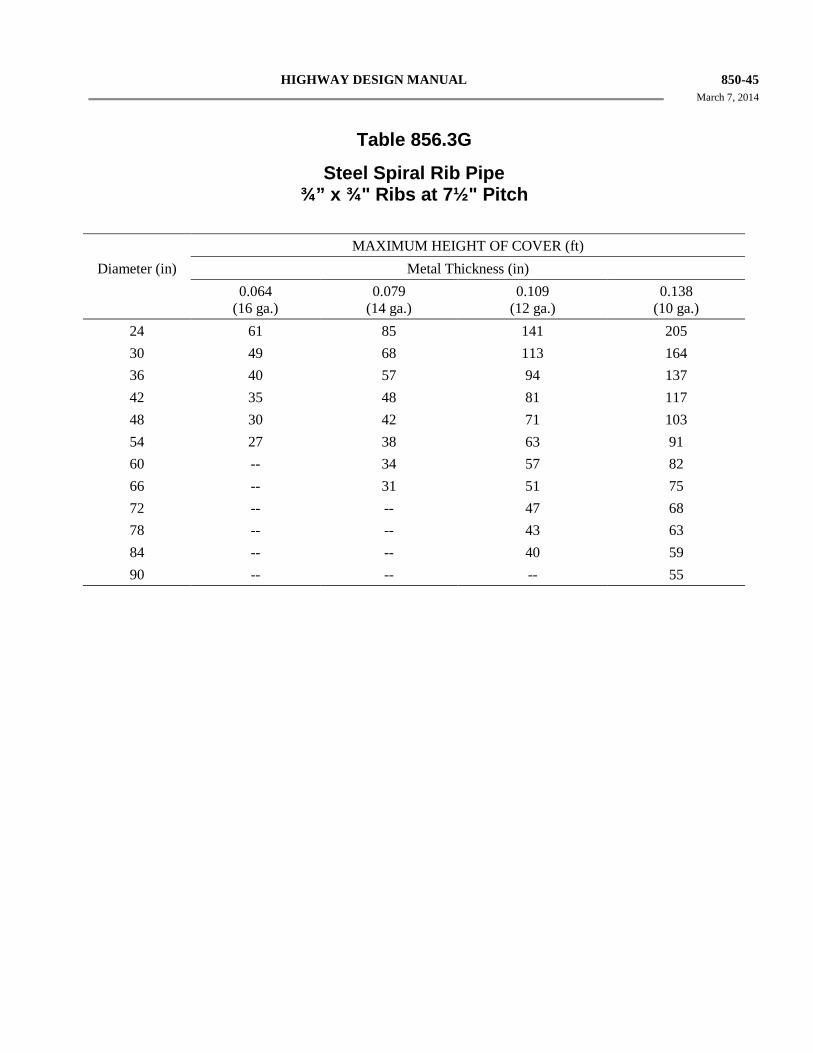
HIGHWAY DESIGN MANUAL 850-45 March 7, 2014
Table 856.3G
Steel Spiral Rib Pipe ¾” x ¾" Ribs at 7½" Pitch
MAXIMUM HEIGHT OF COVER (ft)
Diameter (in) Metal Thickness (in) 0.064
(16 ga.) 0.079
(14 ga.) 0.109
(12 ga.) 0.138
(10 ga.)
24 61 85 141 205 30 49 68 113 164 36 40 57 94 137 42 35 48 81 117 48 30 42 71 103 54 27 38 63 91 60 -- 34 57 82 66 -- 31 51 75 72 -- -- 47 68 78 -- -- 43 63 84 -- -- 40 59 90 -- -- -- 55
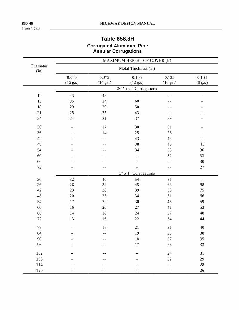
850-46 HIGHWAY DESIGN MANUAL March 7, 2014
Table 856.3H
Corrugated Aluminum Pipe Annular Corrugations
MAXIMUM HEIGHT OF COVER (ft) Diameter
(in) Metal Thickness (in)
0.060 (16 ga.)
0.075 (14 ga.)
0.105 (12 ga.)
0.135 (10 ga.)
0.164 (8 ga.)
2⅔" x ½" Corrugations 12 43 43 -- -- -- 15 35 34 60 -- -- 18 29 29 50 -- -- 21 25 25 43 -- -- 24 21 21 37 39 --
30 -- 17 30 31 -- 36 -- 14 25 26 -- 42 -- -- 43 45 -- 48 -- -- 38 40 41 54 -- -- 34 35 36 60 -- -- -- 32 33 66 -- -- -- -- 30 72 -- -- -- -- 27 3" x 1" Corrugations 30 32 40 54 81 -- 36 26 33 45 68 88 42 23 28 39 58 75 48 20 25 34 51 66 54 17 22 30 45 59 60 16 20 27 41 53 66 14 18 24 37 48 72 13 16 22 34 44
78 -- 15 21 31 40 84 -- -- 19 29 38 90 -- -- 18 27 35 96 -- -- 17 25 33
102 -- -- -- 24 31 108 -- -- -- 22 29 114 -- -- -- -- 28 120 -- -- -- -- 26
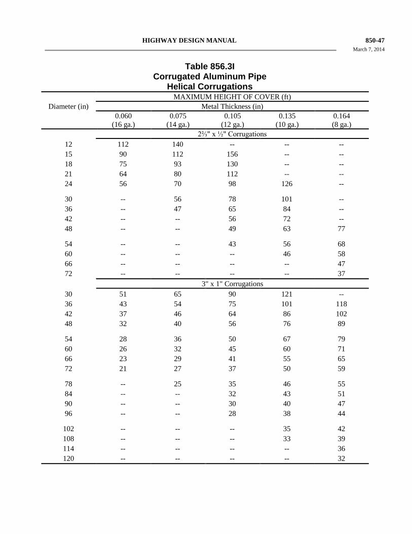
HIGHWAY DESIGN MANUAL 850-47 March 7, 2014
Table 856.3I
Corrugated Aluminum Pipe Helical Corrugations
MAXIMUM HEIGHT OF COVER (ft) Diameter (in) Metal Thickness (in)
0.060 (16 ga.)
0.075 (14 ga.)
0.105 (12 ga.)
0.135 (10 ga.)
0.164 (8 ga.)
2⅔" x ½" Corrugations 12 112 140 -- -- -- 15 90 112 156 -- -- 18 75 93 130 -- -- 21 64 80 112 -- -- 24 56 70 98 126 --
30 -- 56 78 101 -- 36 -- 47 65 84 -- 42 -- -- 56 72 -- 48 -- -- 49 63 77
54 -- -- 43 56 68 60 -- -- -- 46 58 66 -- -- -- -- 47 72 -- -- -- -- 37
3" x 1" Corrugations 30 51 65 90 121 -- 36 43 54 75 101 118 42 37 46 64 86 102 48 32 40 56 76 89
54 28 36 50 67 79 60 26 32 45 60 71 66 23 29 41 55 65 72 21 27 37 50 59
78 -- 25 35 46 55 84 -- -- 32 43 51 90 -- -- 30 40 47 96 -- -- 28 38 44
102 -- -- -- 35 42 108 -- -- -- 33 39 114 -- -- -- -- 36 120 -- -- -- -- 32
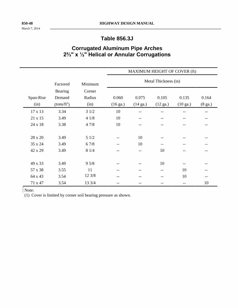
850-48 HIGHWAY DESIGN MANUAL March 7, 2014
Table 856.3J
Corrugated Aluminum Pipe Arches 2⅔" x ½" Helical or Annular Corrugations
MAXIMUM HEIGHT OF COVER (ft)
Factored
Minimum Metal Thickness (in)
Bearing Corner Span-Rise Demand Radius 0.060 0.075 0.105 0.135 0.164 (in) (tons/ft2) (in) (16 ga.) (14 ga.) (12 ga.) (10 ga.) (8 ga.)
17 x 13 3.34 3 1/2 10 -- -- -- -- 21 x 15 3.49 4 1/8 10 -- -- -- -- 24 x 18 3.38 4 7/8 10 -- -- -- -- 28 x 20 3.49 5 1/2 -- 10 -- -- -- 35 x 24 3.49 6 7/8 -- 10 -- -- -- 42 x 29 3.49 8 1/4 -- -- 10 -- -- 49 x 33 3.49 9 5/8 -- -- 10 -- -- 57 x 38 3.55 11 -- -- -- 10 -- 64 x 43 3.54 12 3/8 -- -- -- 10 -- 71 x 47 3.54 13 3/4 -- -- -- -- 10
Note: (1) Cover is limited by corner soil bearing pressure as shown.
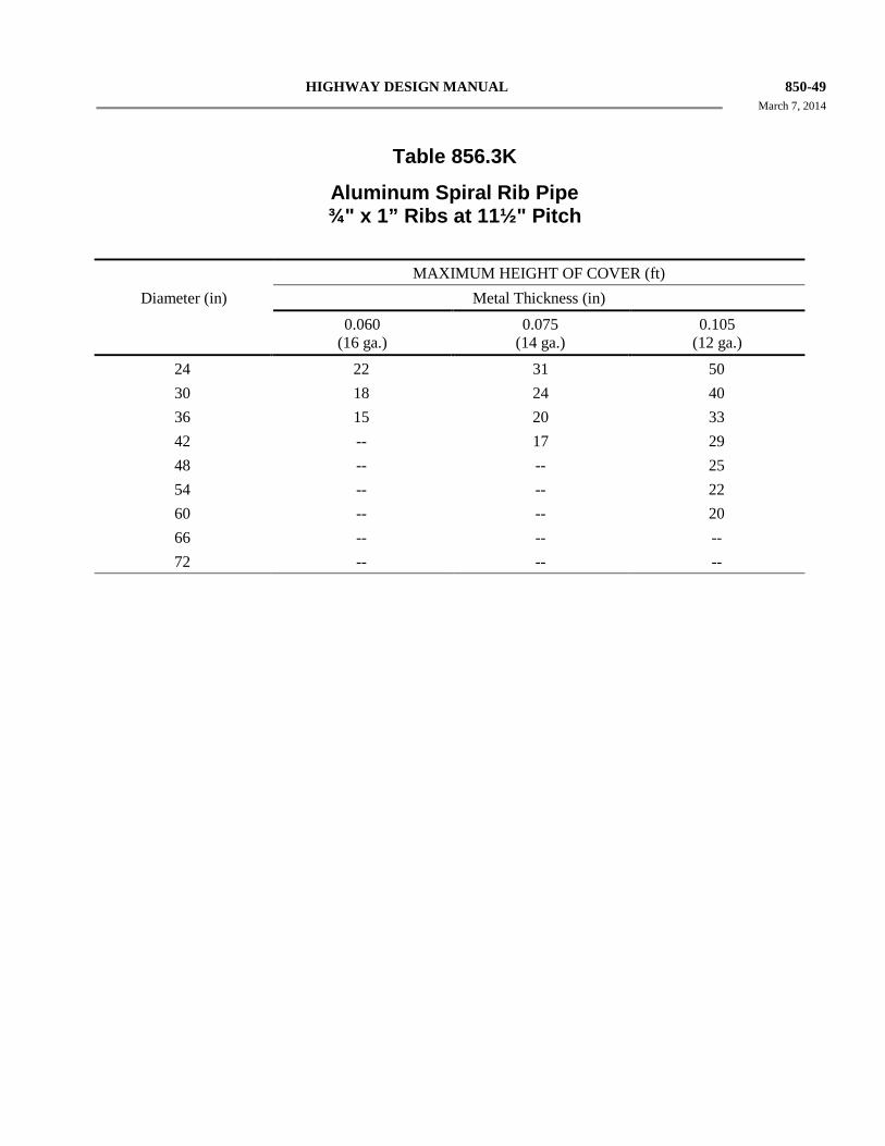
HIGHWAY DESIGN MANUAL 850-49 March 7, 2014
Table 856.3K
Aluminum Spiral Rib Pipe ¾" x 1” Ribs at 11½" Pitch
MAXIMUM HEIGHT OF COVER (ft) Diameter (in) Metal Thickness (in) 0.060
(16 ga.) 0.075
(14 ga.) 0.105
(12 ga.)
24 22 31 50 30 18 24 40 36 15 20 33 42 -- 17 29 48 -- -- 25 54 -- -- 22 60 -- -- 20 66 -- -- -- 72 -- -- --
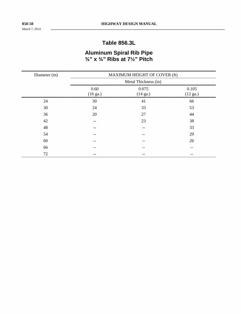
850-50 HIGHWAY DESIGN MANUAL March 7, 2014
Table 856.3L
Aluminum Spiral Rib Pipe ¾" x ¾" Ribs at 7½" Pitch
Diameter (in) MAXIMUM HEIGHT OF COVER (ft) Metal Thickness (in) 0.60
(16 ga.) 0.075
(14 ga.) 0.105
(12 ga.)
24 30 41 66 30 24 33 53 36 20 27 44 42 -- 23 38 48 -- -- 33 54 -- -- 29 60 -- -- 26 66 -- -- -- 72 -- -- --
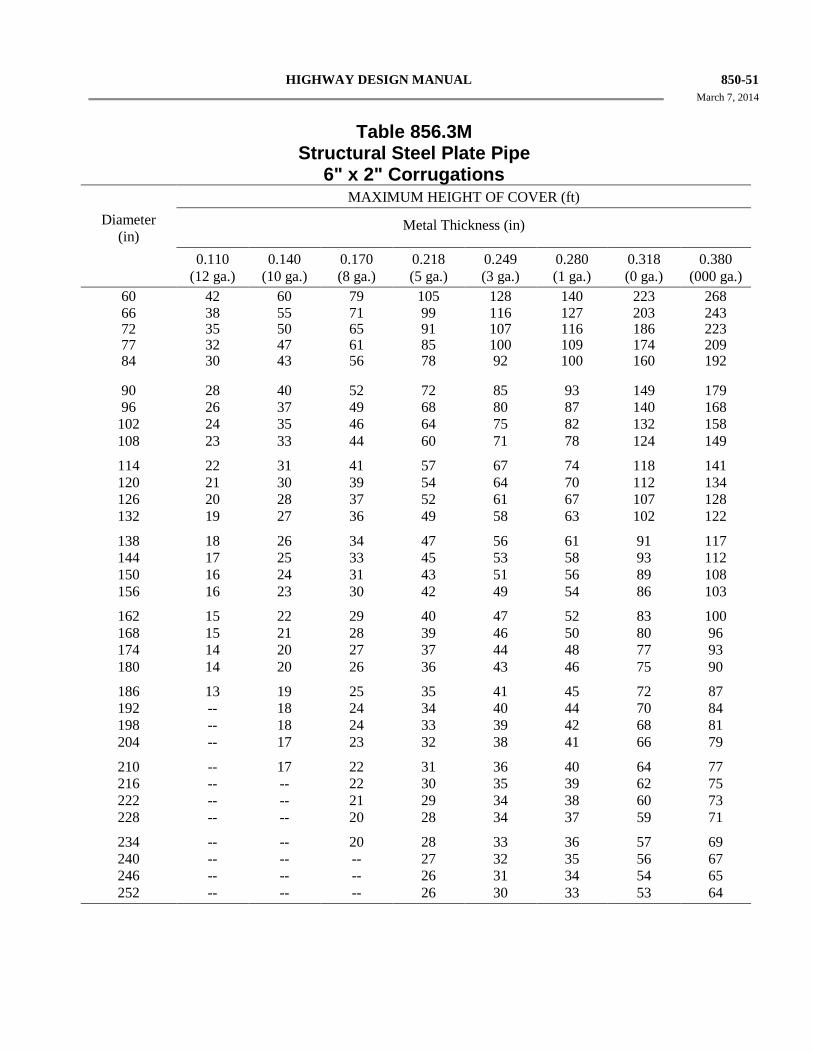
HIGHWAY DESIGN MANUAL 850-51 March 7, 2014
Table 856.3M
Structural Steel Plate Pipe 6" x 2" Corrugations
MAXIMUM HEIGHT OF COVER (ft) Diameter
(in) Metal Thickness (in)
0.110 (12 ga.)
0.140 (10 ga.)
0.170 (8 ga.)
0.218 (5 ga.)
0.249 (3 ga.)
0.280 (1 ga.)
0.318 (0 ga.)
0.380 (000 ga.)
60 42 60 79 105 128 140 223 268 66 38 55 71 99 116 127 203 243 72 35 50 65 91 107 116 186 223 77 32 47 61 85 100 109 174 209 84 30 43 56 78 92 100 160 192
90 28 40 52 72 85 93 149 179 96 26 37 49 68 80 87 140 168 102 24 35 46 64 75 82 132 158 108 23 33 44 60 71 78 124 149
114 22 31 41 57 67 74 118 141 120 21 30 39 54 64 70 112 134 126 20 28 37 52 61 67 107 128 132 19 27 36 49 58 63 102 122
138 18 26 34 47 56 61 91 117 144 17 25 33 45 53 58 93 112 150 16 24 31 43 51 56 89 108 156 16 23 30 42 49 54 86 103
162 15 22 29 40 47 52 83 100 168 15 21 28 39 46 50 80 96 174 14 20 27 37 44 48 77 93 180 14 20 26 36 43 46 75 90
186 13 19 25 35 41 45 72 87 192 -- 18 24 34 40 44 70 84 198 -- 18 24 33 39 42 68 81 204 -- 17 23 32 38 41 66 79
210 -- 17 22 31 36 40 64 77 216 -- -- 22 30 35 39 62 75 222 -- -- 21 29 34 38 60 73 228 -- -- 20 28 34 37 59 71
234 -- -- 20 28 33 36 57 69 240 -- -- -- 27 32 35 56 67 246 -- -- -- 26 31 34 54 65 252 -- -- -- 26 30 33 53 64
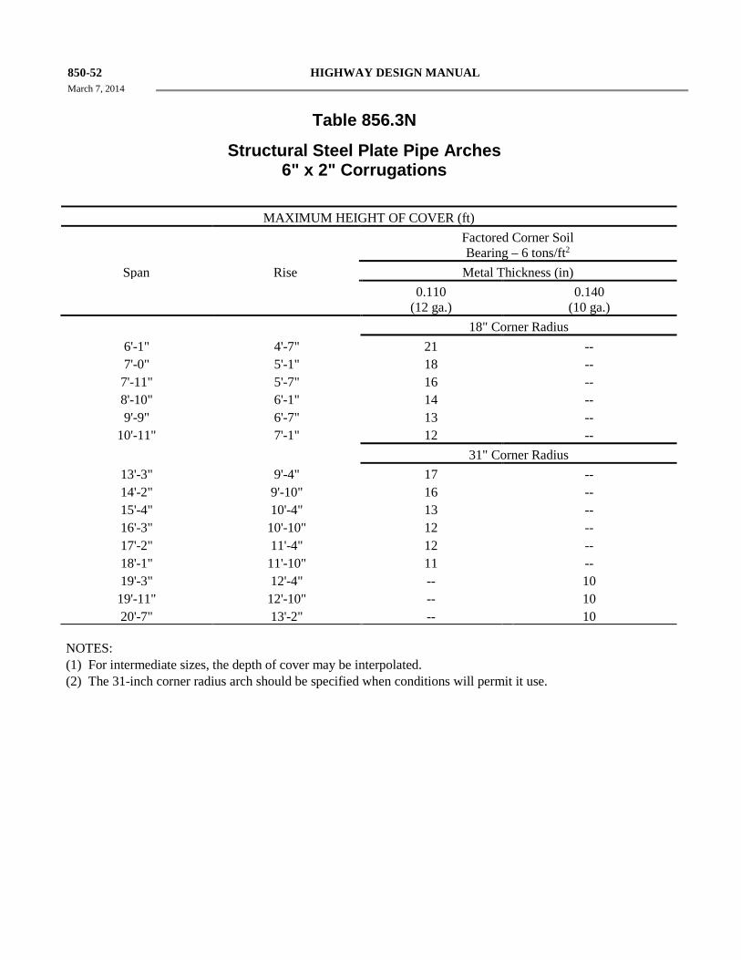
850-52 HIGHWAY DESIGN MANUAL March 7, 2014
Table 856.3N
Structural Steel Plate Pipe Arches 6" x 2" Corrugations
MAXIMUM HEIGHT OF COVER (ft)
Factored Corner Soil Bearing – 6 tons/ft2
Span Rise Metal Thickness (in) 0.110
(12 ga.) 0.140
(10 ga.) 18" Corner Radius
6'-1" 4'-7" 21 -- 7'-0" 5'-1" 18 -- 7'-11" 5'-7" 16 -- 8'-10" 6'-1" 14 -- 9'-9" 6'-7" 13 --
10'-11" 7'-1" 12 -- 31" Corner Radius
13'-3" 9'-4" 17 -- 14'-2" 9'-10" 16 -- 15'-4" 10'-4" 13 -- 16'-3" 10'-10" 12 -- 17'-2" 11'-4" 12 -- 18'-1" 11'-10" 11 -- 19'-3" 12'-4" -- 10
19'-11" 12'-10" -- 10 20'-7" 13'-2" -- 10
NOTES:
(1) For intermediate sizes, the depth of cover may be interpolated. (2) The 31-inch corner radius arch should be specified when conditions will permit it use.
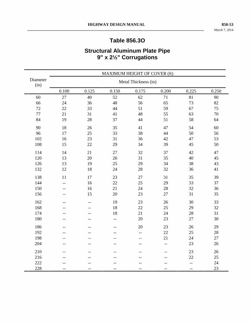
HIGHWAY DESIGN MANUAL 850-53 March 7, 2014
Table 856.3O
Structural Aluminum Plate Pipe 9" x 2½" Corrugations
MAXIMUM HEIGHT OF COVER (ft)
Diameter (in)
Metal Thickness (in)
0.100 0.125 0.150 0.175 0.200 0.225 0.250 60 27 40 52 62 71 81 90 66 24 36 48 56 65 73 82 72 22 33 44 51 59 67 75 77 21 31 41 48 55 63 70 84 19 28 37 44 51 58 64
90 18 26 35 41 47 54 60 96 17 25 33 38 44 50 56 102 16 23 31 36 42 47 53 108 15 22 29 34 39 45 50
114 14 21 27 32 37 42 47 120 13 20 26 31 35 40 45 126 13 19 25 29 34 38 43 132 12 18 24 28 32 36 41
138 11 17 23 27 31 35 39 144 -- 16 22 25 29 33 37 150 -- 16 21 24 28 32 36 156 -- 15 20 23 27 31 35
162 -- -- 19 23 26 30 33 168 -- -- 18 22 25 29 32 174 -- -- 18 21 24 28 31 180 -- -- -- 20 23 27 30
186 -- -- -- 20 23 26 29 192 -- -- -- -- 22 25 28 198 -- -- -- -- 21 24 27 204 -- -- -- -- -- 23 26
210 -- -- -- -- -- 23 26 216 -- -- -- -- -- 22 25 222 -- -- -- -- -- -- 24 228 -- -- -- -- -- -- 23
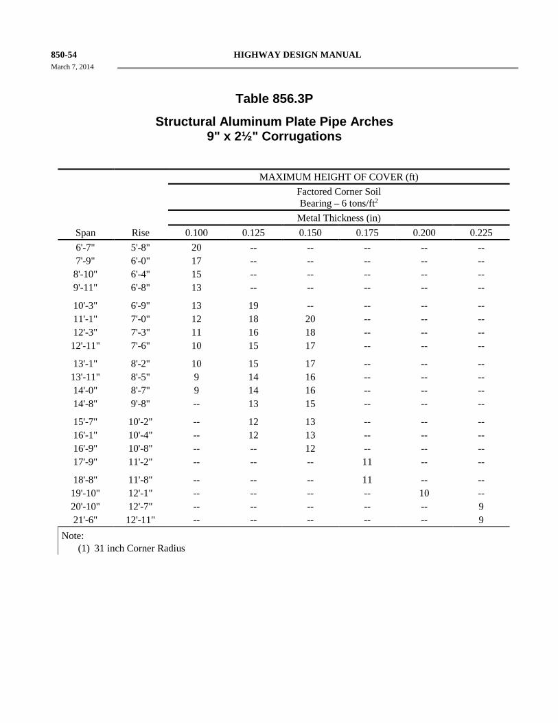
850-54 HIGHWAY DESIGN MANUAL March 7, 2014
Table 856.3P
Structural Aluminum Plate Pipe Arches 9" x 2½" Corrugations
MAXIMUM HEIGHT OF COVER (ft) Factored Corner Soil
Bearing – 6 tons/ft2
Metal Thickness (in) Span Rise 0.100 0.125 0.150 0.175 0.200 0.225 6'-7" 5'-8" 20 -- -- -- -- -- 7'-9" 6'-0" 17 -- -- -- -- -- 8'-10" 6'-4" 15 -- -- -- -- -- 9'-11" 6'-8" 13 -- -- -- -- --
10'-3" 6'-9" 13 19 -- -- -- -- 11'-1" 7'-0" 12 18 20 -- -- -- 12'-3" 7'-3" 11 16 18 -- -- -- 12'-11" 7'-6" 10 15 17 -- -- --
13'-1" 8'-2" 10 15 17 -- -- -- 13'-11" 8'-5" 9 14 16 -- -- -- 14'-0" 8'-7" 9 14 16 -- -- -- 14'-8" 9'-8" -- 13 15 -- -- --
15'-7" 10'-2" -- 12 13 -- -- -- 16'-1" 10'-4" -- 12 13 -- -- -- 16'-9" 10'-8" -- -- 12 -- -- -- 17'-9" 11'-2" -- -- -- 11 -- --
18'-8" 11'-8" -- -- -- 11 -- -- 19'-10" 12'-1" -- -- -- -- 10 -- 20'-10" 12'-7" -- -- -- -- -- 9 21'-6" 12'-11" -- -- -- -- -- 9
Note: (1) 31 inch Corner Radius
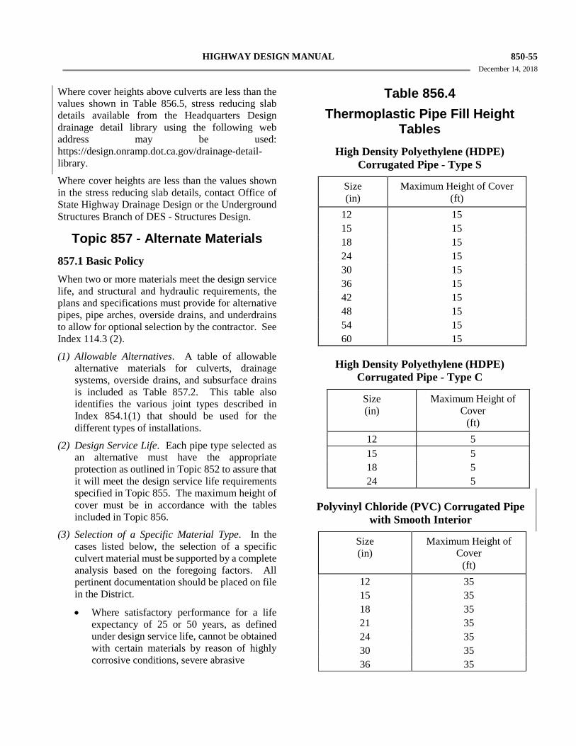
HIGHWAY DESIGN MANUAL 850-55 December 14, 2018
Where cover heights above culverts are less than the values shown in Table 856.5, stress reducing slab details available from the Headquarters Design drainage detail library using the following web address may be used: https://design.onramp.dot.ca.gov/drainage-detail-library.
Where cover heights are less than the values shown in the stress reducing slab details, contact Office of State Highway Drainage Design or the Underground Structures Branch of DES - Structures Design.
Topic 857 - Alternate Materials 857.1 Basic Policy When two or more materials meet the design service life, and structural and hydraulic requirements, the plans and specifications must provide for alternative pipes, pipe arches, overside drains, and underdrains to allow for optional selection by the contractor. See Index 114.3 (2).
(1) Allowable Alternatives. A table of allowable alternative materials for culverts, drainage systems, overside drains, and subsurface drains is included as Table 857.2. This table also identifies the various joint types described in Index 854.1(1) that should be used for the different types of installations.
(2) Design Service Life. Each pipe type selected as an alternative must have the appropriate protection as outlined in Topic 852 to assure that it will meet the design service life requirements specified in Topic 855. The maximum height of cover must be in accordance with the tables included in Topic 856.
(3) Selection of a Specific Material Type. In the cases listed below, the selection of a specific culvert material must be supported by a complete analysis based on the foregoing factors. All pertinent documentation should be placed on file in the District.
• Where satisfactory performance for a life expectancy of 25 or 50 years, as defined under design service life, cannot be obtained with certain materials by reason of highly corrosive conditions, severe abrasive
Table 856.4
Thermoplastic Pipe Fill Height Tables
High Density Polyethylene (HDPE) Corrugated Pipe - Type S
Size (in)
Maximum Height of Cover (ft)
12 15 15 15 18 15 24 15 30 15 36 15 42 15 48 15 54 15 60 15
High Density Polyethylene (HDPE) Corrugated Pipe - Type C
Size (in)
Maximum Height of Cover
(ft)
12 5 15 5 18 5 24 5
Polyvinyl Chloride (PVC) Corrugated Pipe with Smooth Interior
Size (in)
Maximum Height of Cover
(ft)
12 35 15 35 18 35 21 35 24 35 30 35 36 35
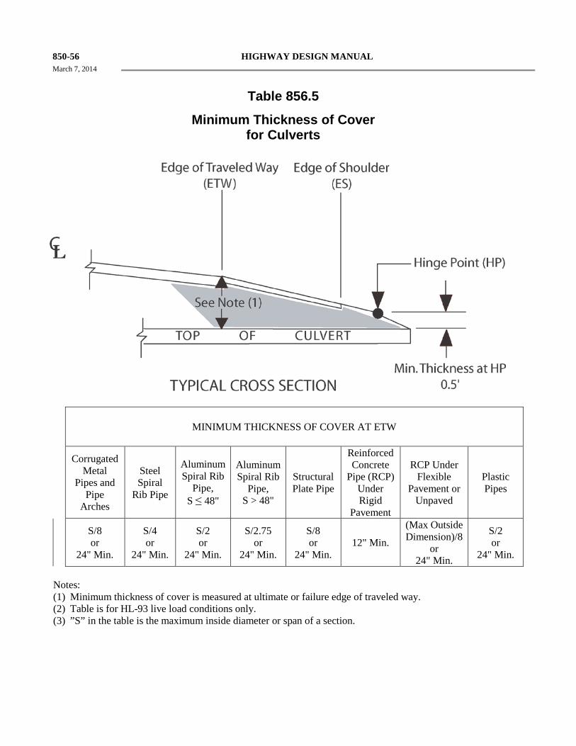
850-56 HIGHWAY DESIGN MANUAL March 7, 2014
Table 856.5
Minimum Thickness of Cover for Culverts
MINIMUM THICKNESS OF COVER AT ETW
Corrugated Metal
Pipes and Pipe
Arches
Steel Spiral
Rib Pipe
Aluminum Spiral Rib
Pipe, S ≤ 48"
Aluminum Spiral Rib
Pipe, S > 48"
Structural Plate Pipe
Reinforced Concrete
Pipe (RCP) Under Rigid
Pavement
RCP Under Flexible
Pavement or Unpaved
Plastic Pipes
S/8 or
24" Min.
S/4 or
24" Min.
S/2 or
24" Min.
S/2.75 or
24" Min.
S/8 or
24" Min. 12" Min.
(Max Outside Dimension)/8
or 24" Min.
S/2 or
24" Min.
Notes: (1) Minimum thickness of cover is measured at ultimate or failure edge of traveled way. (2) Table is for HL-93 live load conditions only. (3) ”S” in the table is the maximum inside diameter or span of a section.
HIGHWAY DESIGN MANUAL 850-57 March 7, 2014
conditions, or critical structural and
construction requirements.
• For individual drainage systems such as roadway drainage systems or culverts which operate under hydrostatic pressure or culverts governed by hydraulic considerations and which would require separate design for each culvert type.
• When alterations or extensions of existing systems are required, the culvert type may be selected to match the type used in the existing system.
857.2 Alternative Pipe Culvert Selection Procedure Using AltPipe These instructions are general guidelines for alternative pipe culvert selection using the AltPipe computer program that is located on the Headquarters Division of Design alternative pipe culvert selection website at the following web address: http://www.dot.ca.gov/hq/oppd/altpipe.htm.
AltPipe is a web-based tool that may be used to assist materials engineers and designers in the appropriate selection of pipe materials for culvert and storm drain applications. The computations performed by AltPipe are based on the procedures and California Test Methods described in this
Chapter. AltPipe is not a substitute for the appropriate use of engineering judgment as conditions and experience would warrant. AltPipe establishes uniform procedures to assist the designer in carrying out the majority of the alternative pipe culvert selection functions of the Department, and is neither intended as, nor does it establish, a legal standard for these functions. Implementation of the results and output of this program is solely at the discretion of the user. The user is encouraged to first read the two informational links on the website titled ‘Get More Information’ and ‘How to use Altpipe’ prior to using the program.
Each alternative material selected for a drainage facility must provide the required design service life based on physical and structural factors, be of adequate size to satisfy the hydraulic design, and require the minimum of maintenance and construction cost for each site condition.
Step 1. Obtain the results of soil and water pH, resistivity, sulfate and chloride tests, proposed design
life of culverts and make determination if any of the outfalls are in salty or brackish water. The Materials Report should include proposed design life and recommendations for pipe material alternatives. See Indexes 114.2 (3) and 114.3 (2).
Step 2. Obtain hydraulic studies and location data for pipe minimum sizes, and expected Q2-5 flow velocities. For pipes operating under outlet control, a critical element of pipe selection is the Manning’s internal roughness value used in the hydraulic design. It is important to independently verify the roughness used in the design is applicable for the selected alternate materials from AltPipe. Rougher pipes may require larger sizes to provide adequate hydraulic capacities and need steeper slopes to produce desired cleaning velocities, usually however, pipe slope is maintained, and the only variable provided on the plans is pipe size.
Step 3. Determine the abrasion level from Table 852.2A from the maximum size of material that can be moved through a pipe, the expected Q2-5 flow velocities, and Table 855.2B. Field observations of channel bed material both upstream and downstream are recommended.
Step 4. Determine the maximum fill height.
Step 5. Using the AltPipe computer program that is located on the Headquarters Division of Design alternative pipe culvert selection website enter:
• Pipe diameter
• Maximum fill height
• Design service life
• pH
• Minimum resistivity
• Sulfate concentration
• Chloride concentration (for values greater than 2000, check boxes if end of culvert is exposed to brackish conditions and high tide line is below the crown of the culvert)
• Abrasion level
• 2-5-year Storm Flow Velocity (ft/sec)
Repeat step 5 as necessary and save each pipe in worksheet as needed and go to the final summary upon completion.
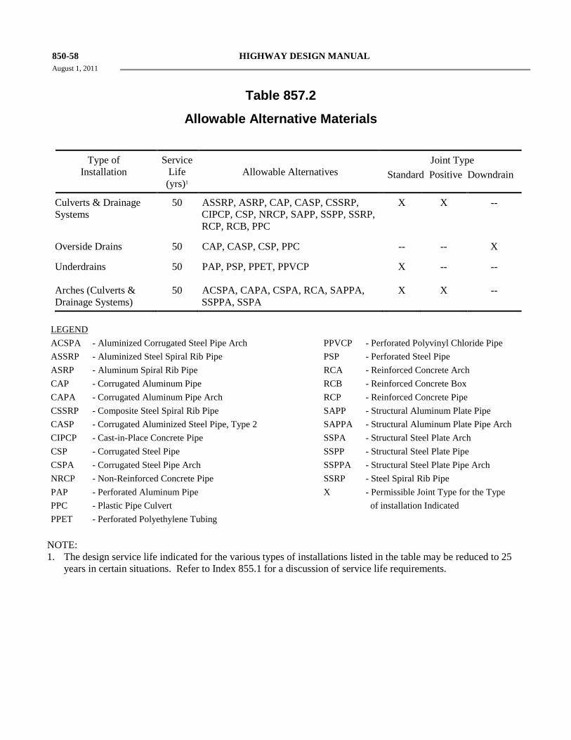
850-58 HIGHWAY DESIGN MANUAL August 1, 2011
Table 857.2
Allowable Alternative Materials
Type of Installation
Service Life (yrs)1
Allowable Alternatives
Joint Type Standard Positive Downdrain
Culverts & Drainage Systems
50 ASSRP, ASRP, CAP, CASP, CSSRP, CIPCP, CSP, NRCP, SAPP, SSPP, SSRP, RCP, RCB, PPC
X X --
Overside Drains 50 CAP, CASP, CSP, PPC -- -- X
Underdrains 50 PAP, PSP, PPET, PPVCP X -- --
Arches (Culverts & Drainage Systems)
50 ACSPA, CAPA, CSPA, RCA, SAPPA, SSPPA, SSPA X X --
LEGEND ACSPA - Aluminized Corrugated Steel Pipe Arch PPVCP - Perforated Polyvinyl Chloride Pipe ASSRP - Aluminized Steel Spiral Rib Pipe PSP - Perforated Steel Pipe ASRP - Aluminum Spiral Rib Pipe RCA - Reinforced Concrete Arch CAP - Corrugated Aluminum Pipe RCB - Reinforced Concrete Box CAPA - Corrugated Aluminum Pipe Arch RCP - Reinforced Concrete Pipe CSSRP - Composite Steel Spiral Rib Pipe SAPP - Structural Aluminum Plate Pipe CASP - Corrugated Aluminized Steel Pipe, Type 2 SAPPA - Structural Aluminum Plate Pipe Arch CIPCP - Cast-in-Place Concrete Pipe SSPA - Structural Steel Plate Arch CSP - Corrugated Steel Pipe SSPP - Structural Steel Plate Pipe CSPA - Corrugated Steel Pipe Arch SSPPA - Structural Steel Plate Pipe Arch NRCP - Non-Reinforced Concrete Pipe SSRP - Steel Spiral Rib Pipe PAP - Perforated Aluminum Pipe X - Permissible Joint Type for the Type PPC - Plastic Pipe Culvert of installation Indicated PPET - Perforated Polyethylene Tubing
NOTE: 1. The design service life indicated for the various types of installations listed in the table may be reduced to 25
years in certain situations. Refer to Index 855.1 for a discussion of service life requirements.
HIGHWAY DESIGN MANUAL 850-59 March 7, 2014
Step 6. The following alternatives are not included in AltPipe and will not be provided in the output Alternative pipe list: all non-circular shapes (arches, boxes, etc.), non reinforced concrete pipe (NRCP) and non-standard new products. Check Materials and Hydraulics reports and verify if any of these alternatives were recommended and supplement the AltPipe final summary accordingly. For reinforced concrete pipe (RCP), box (RCB) and arch (RCA) culverts, maintenance-free service life, with respect to corrosion, abrasion and/or durability, is the number of years from installation until the deterioration reaches the point of exposed reinforcement at any point on the culvert. Changes in the design may be required in relatively severe acidic, chloride or sulfate environments. The levels of these constituents (either in the soil or water) will need to be identified in the project Materials or Geotechnical Design Report. The adopted procedure consists of a formula that the constituent concentrations are entered into in order to determine a pipe service life. The means for offsetting the affects of the corrosive elements is to increase the cover over the reinforcing steel, increase the cement content, or reduce the water/cement ratio.
Step 7. Table 855.2C constitutes a guide for abrasive resistant coatings in low to moderate abrasive conditions for metal pipe (i.e., Levels 1 through 5 in Table 855.2A) and is included in AltPipe. Table 855.2F constitutes a guide for minimum material thickness of abrasive resistant invert protection to achieve 50 years of maintenance-free service life in moderate to highly abrasive conditions (i.e., Levels 4 through 6 in Table 855.2A) and was not programmed into AltPipe. If pipe material thickness does not meet service life due to abrasive conditions, consideration for invert protection should be made using Table 855.2F as a guide.
857.3 Alternative Pipe Culvert (APC) and Pipe Arch Culvert List Because of the difference in roughness coefficients between various materials, it may be necessary to specify a different size for each allowable material at any one location. In this event, it is recommended that the material with the smallest dimension be listed as the alternative size. Refer to Plans Preparation Manual for standard format to be used.
There may be situations where there is a different set of alternatives for the same nominal size of
alternative drainage facilities. In this case the different sets of the same nominal size should be further identified by different types, for example, 18-inch alternative pipe culvert (Type A), 18-inch alternative pipe culvert (Type B), etc. No attempt to correlate type designation between projects is necessary. The first alternative combination for each culvert size on each project should be designated as Type A, second as Type B, etc.
Since the available nominal sizes for pipe arches vary slightly between pipe arch materials, it is recommended that the listed alternative pipe arch sizes conform to those sizes shown for corrugated steel pipe arches shown on Table 856.3D. The designer should verify the availability of reinforced concrete pipe arches. If reinforced concrete pipe arches are not available, oval shaped reinforced concrete pipe of a size necessary to meet the hydraulic requirements may be used as an alternative.