Embed Size (px)
Citation preview
Chapter 8: The Complete Response of RL and RC Circuits
©2001, John Wiley & Sons, Inc.Introduction To Electric Circuits, 5th Ed
Chapter 8
The Complete Response of RL and RC Circuits
Chapter 8: The Complete Response of RL and RC Circuits
©2001, John Wiley & Sons, Inc.Introduction To Electric Circuits, 5th Ed
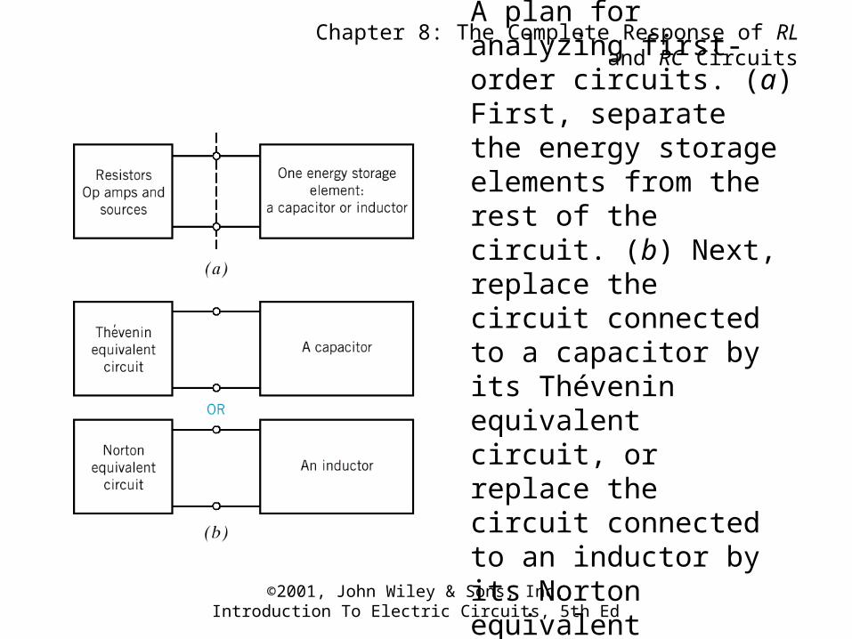
Figure 8.0-1A plan for analyzing first-order circuits. (a) First, separate the energy storage elements from the rest of the circuit. (b) Next, replace the circuit connected to a capacitor by its Thévenin equivalent circuit, or replace the circuit connected to an inductor by its Norton equivalent circuit.
Chapter 8: The Complete Response of RL and RC Circuits
©2001, John Wiley & Sons, Inc.Introduction To Electric Circuits, 5th Ed
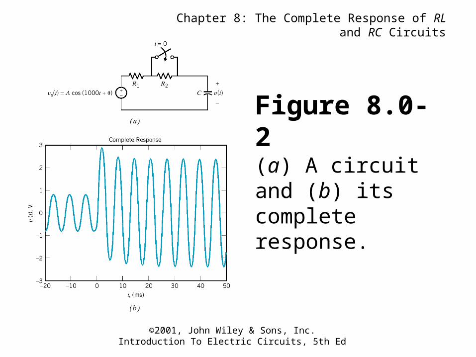
Figure 8.0-2(a) A circuit and (b) its complete response.
Chapter 8: The Complete Response of RL and RC Circuits
©2001, John Wiley & Sons, Inc.Introduction To Electric Circuits, 5th Ed
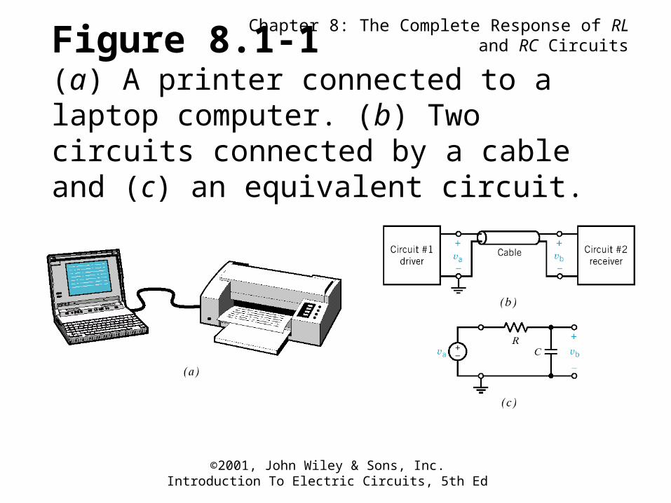
Figure 8.1-1(a) A printer connected to a laptop computer. (b) Two circuits connected by a cable and (c) an equivalent circuit.
Chapter 8: The Complete Response of RL and RC Circuits
©2001, John Wiley & Sons, Inc.Introduction To Electric Circuits, 5th Ed
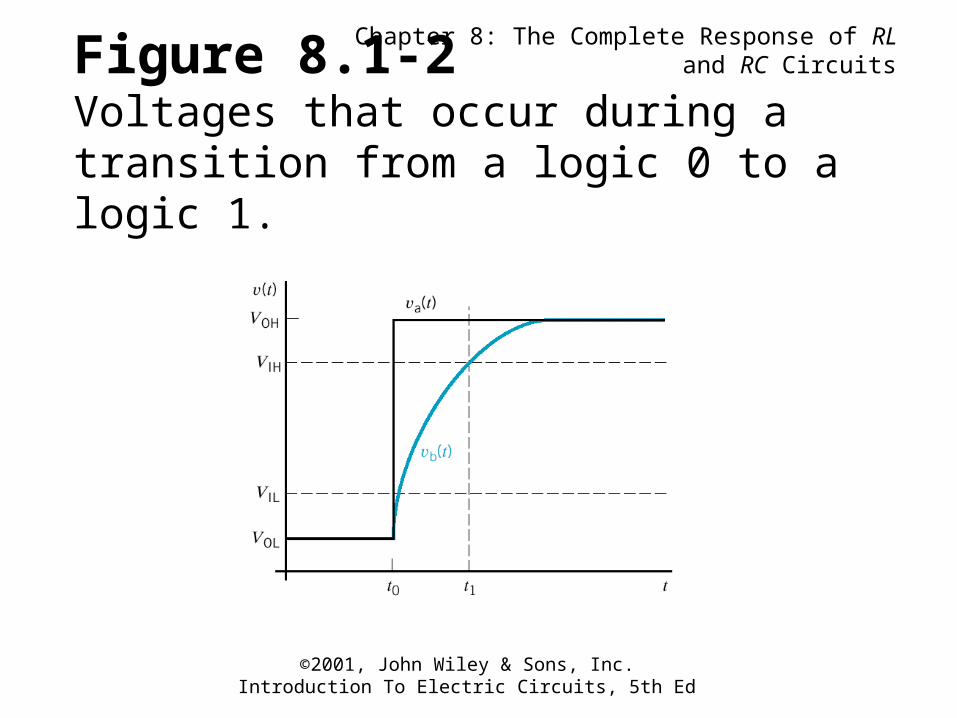
Figure 8.1-2Voltages that occur during a transition from a logic 0 to a logic 1.
Chapter 8: The Complete Response of RL and RC Circuits
©2001, John Wiley & Sons, Inc.Introduction To Electric Circuits, 5th Ed
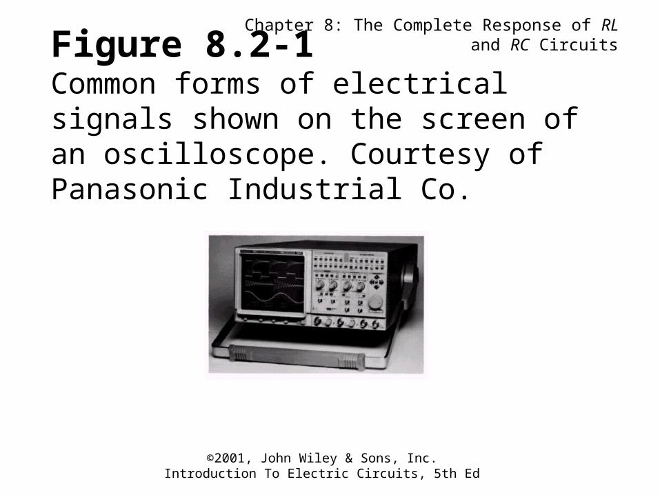
Figure 8.2-1Common forms of electrical signals shown on the screen of an oscilloscope. Courtesy of Panasonic Industrial Co.
Chapter 8: The Complete Response of RL and RC Circuits
©2001, John Wiley & Sons, Inc.Introduction To Electric Circuits, 5th Ed
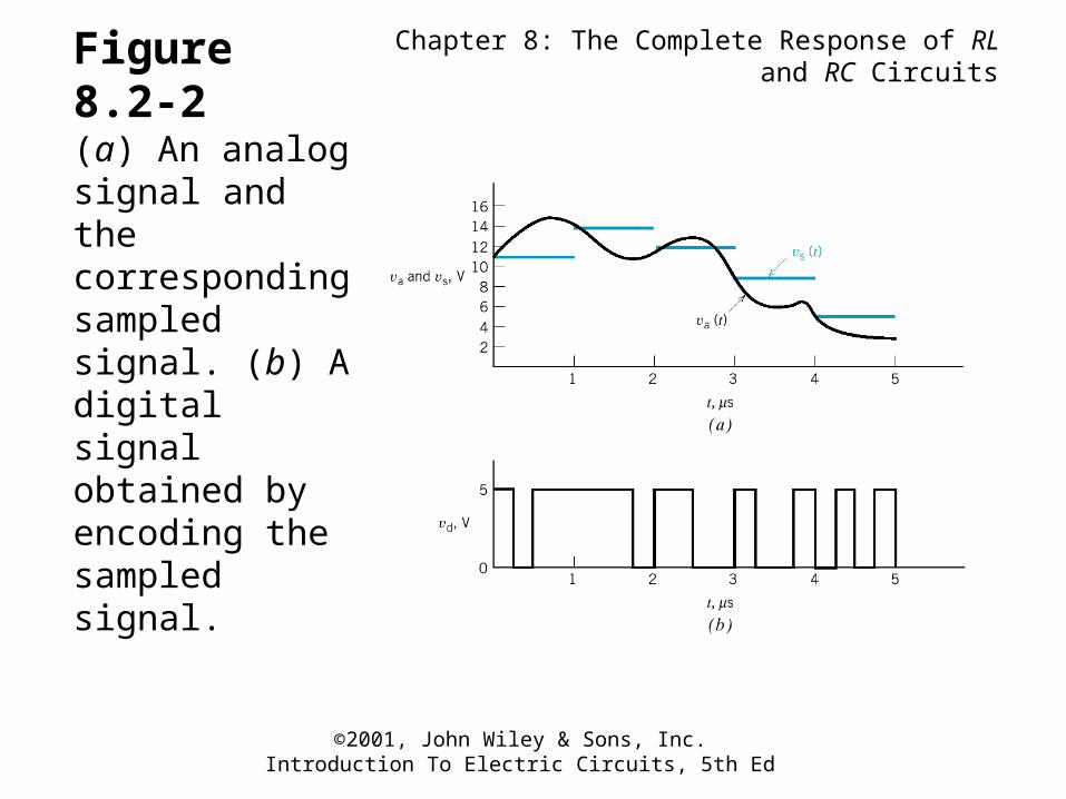
Figure 8.2-2(a) An analog signal and the corresponding sampled signal. (b) A digital signal obtained by encoding the sampled signal.
Chapter 8: The Complete Response of RL and RC Circuits
©2001, John Wiley & Sons, Inc.Introduction To Electric Circuits, 5th Ed
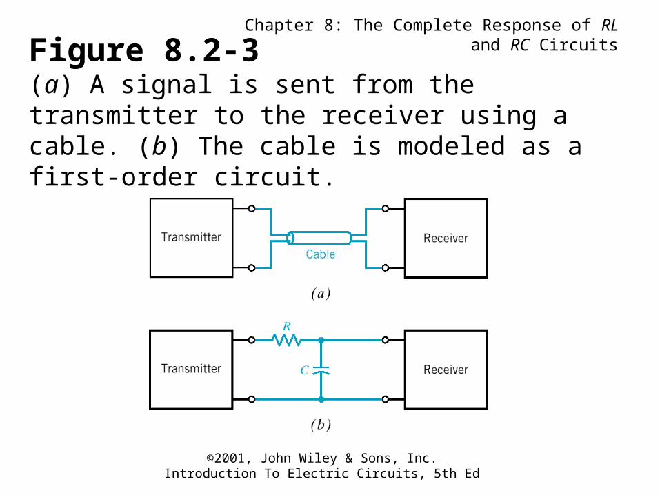
Figure 8.2-3(a) A signal is sent from the transmitter to the receiver using a cable. (b) The cable is modeled as a first-order circuit.
Chapter 8: The Complete Response of RL and RC Circuits
©2001, John Wiley & Sons, Inc.Introduction To Electric Circuits, 5th Ed
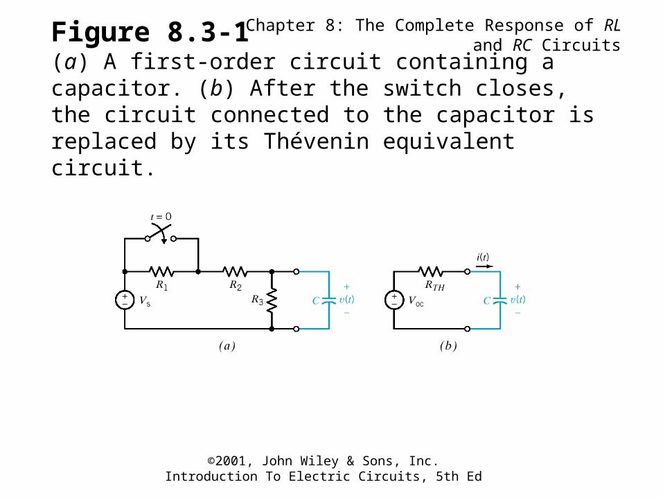
Figure 8.3-1(a) A first-order circuit containing a capacitor. (b) After the switch closes, the circuit connected to the capacitor is replaced by its Thévenin equivalent circuit.
Chapter 8: The Complete Response of RL and RC Circuits
©2001, John Wiley & Sons, Inc.Introduction To Electric Circuits, 5th Ed
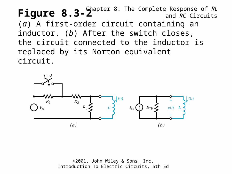
Figure 8.3-2(a) A first-order circuit containing an inductor. (b) After the switch closes, the circuit connected to the inductor is replaced by its Norton equivalent circuit.
Chapter 8: The Complete Response of RL and RC Circuits
©2001, John Wiley & Sons, Inc.Introduction To Electric Circuits, 5th Ed
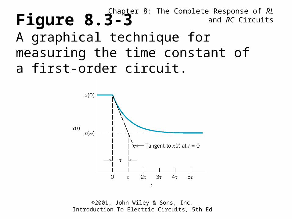
Figure 8.3-3A graphical technique for measuring the time constant of a first-order circuit.
Chapter 8: The Complete Response of RL and RC Circuits
©2001, John Wiley & Sons, Inc.Introduction To Electric Circuits, 5th Ed
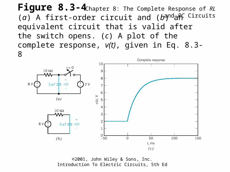
Figure 8.3-4(a) A first-order circuit and (b) an equivalent circuit that is valid after the switch opens. (c) A plot of the complete response, v(t), given in Eq. 8.3-8.
Chapter 8: The Complete Response of RL and RC Circuits
©2001, John Wiley & Sons, Inc.Introduction To Electric Circuits, 5th Ed
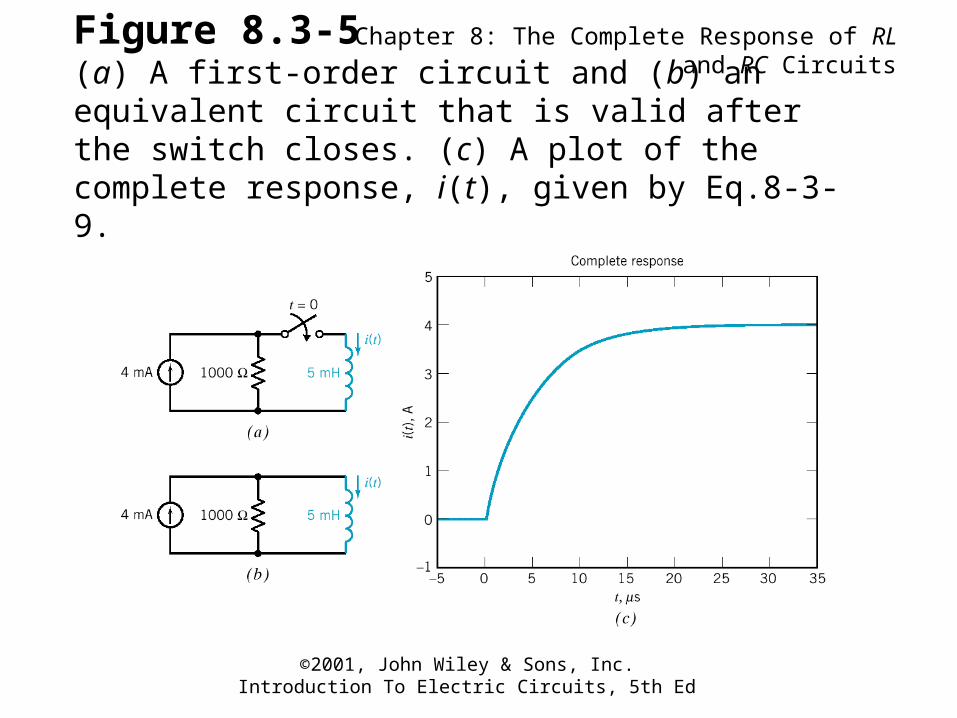
Figure 8.3-5(a) A first-order circuit and (b) an equivalent circuit that is valid after the switch closes. (c) A plot of the complete response, i(t), given by Eq.8-3-9.
Chapter 8: The Complete Response of RL and RC Circuits
©2001, John Wiley & Sons, Inc.Introduction To Electric Circuits, 5th Ed
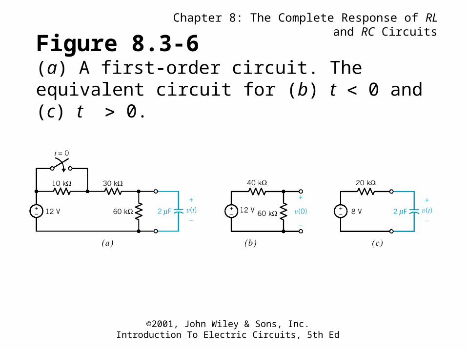
Figure 8.3-6(a) A first-order circuit. The equivalent circuit for (b) t 0 and (c) t 0.
Chapter 8: The Complete Response of RL and RC Circuits
©2001, John Wiley & Sons, Inc.Introduction To Electric Circuits, 5th Ed
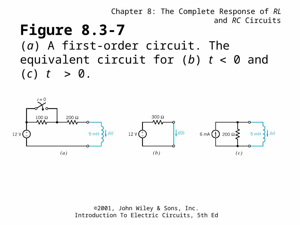
Figure 8.3-7(a) A first-order circuit. The equivalent circuit for (b) t 0 and (c) t 0.
Chapter 8: The Complete Response of RL and RC Circuits
©2001, John Wiley & Sons, Inc.Introduction To Electric Circuits, 5th Ed
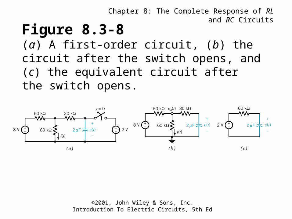
Figure 8.3-8(a) A first-order circuit, (b) the circuit after the switch opens, and (c) the equivalent circuit after the switch opens.
Chapter 8: The Complete Response of RL and RC Circuits
©2001, John Wiley & Sons, Inc.Introduction To Electric Circuits, 5th Ed
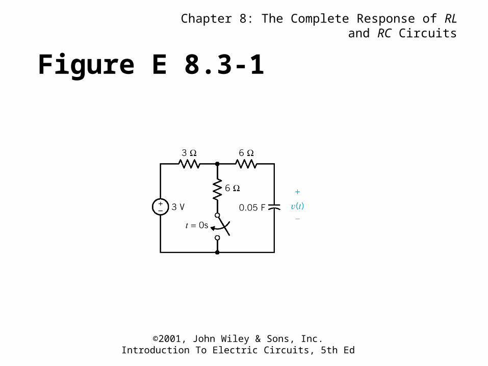
Figure E 8.3-1
Chapter 8: The Complete Response of RL and RC Circuits
©2001, John Wiley & Sons, Inc.Introduction To Electric Circuits, 5th Ed
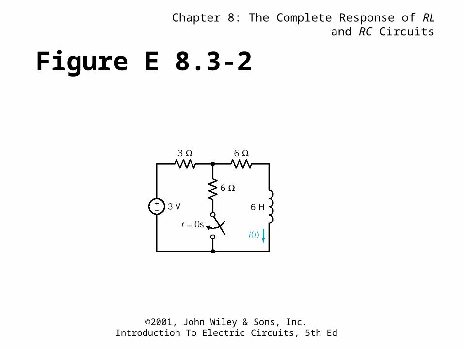
Figure E 8.3-2
Chapter 8: The Complete Response of RL and RC Circuits
©2001, John Wiley & Sons, Inc.Introduction To Electric Circuits, 5th Ed
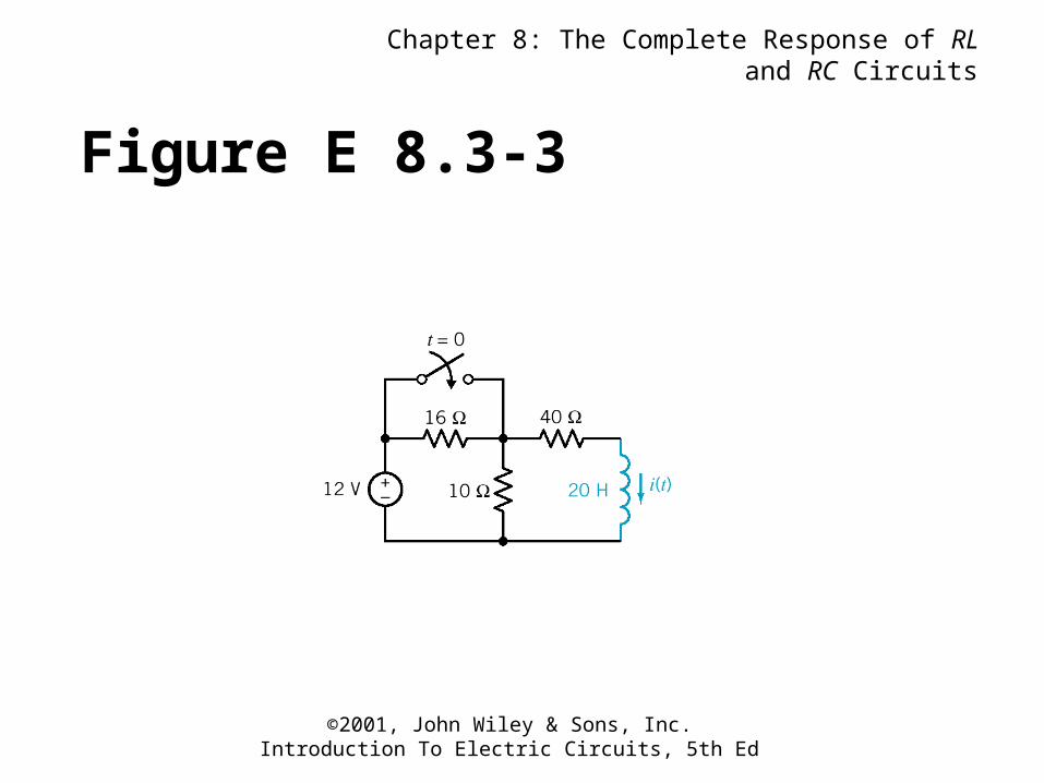
Figure E 8.3-3
Chapter 8: The Complete Response of RL and RC Circuits
©2001, John Wiley & Sons, Inc.Introduction To Electric Circuits, 5th Ed
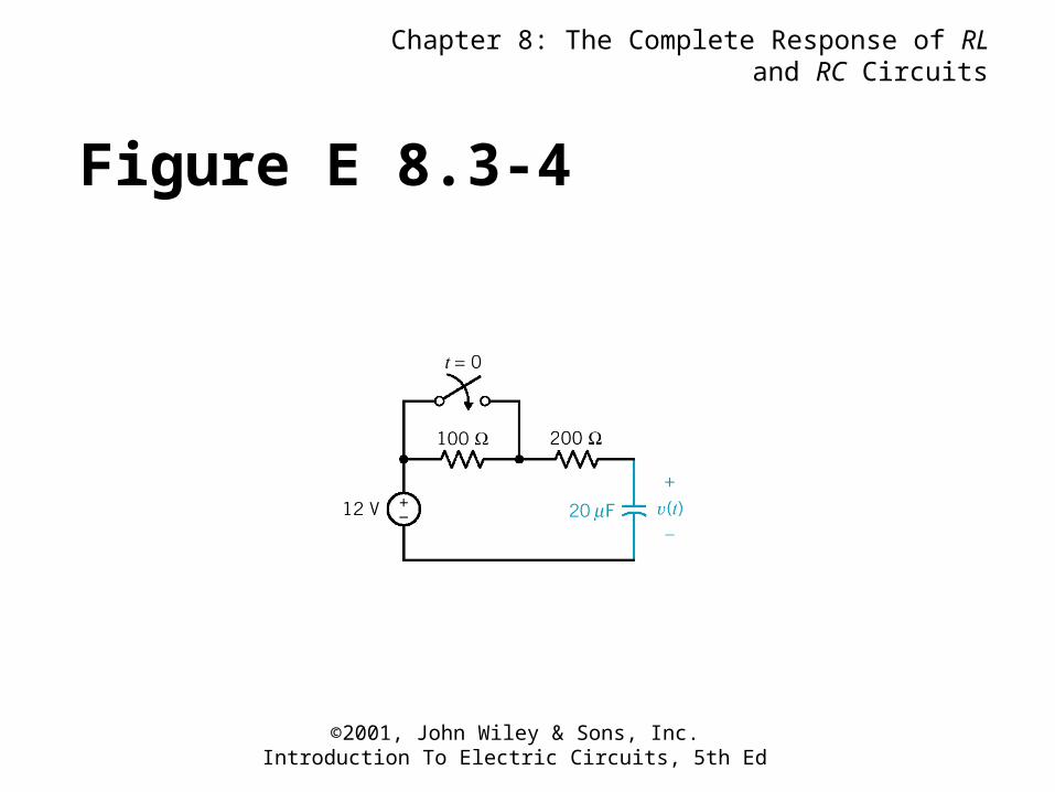
Figure E 8.3-4
Chapter 8: The Complete Response of RL and RC Circuits
©2001, John Wiley & Sons, Inc.Introduction To Electric Circuits, 5th Ed
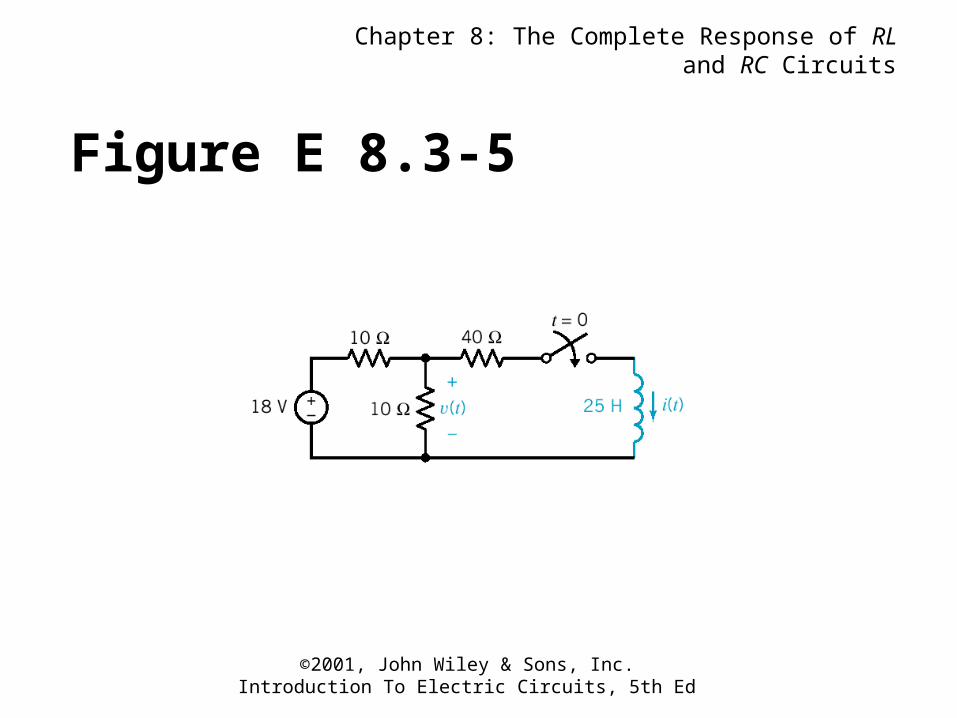
Figure E 8.3-5
Chapter 8: The Complete Response of RL and RC Circuits
©2001, John Wiley & Sons, Inc.Introduction To Electric Circuits, 5th Ed
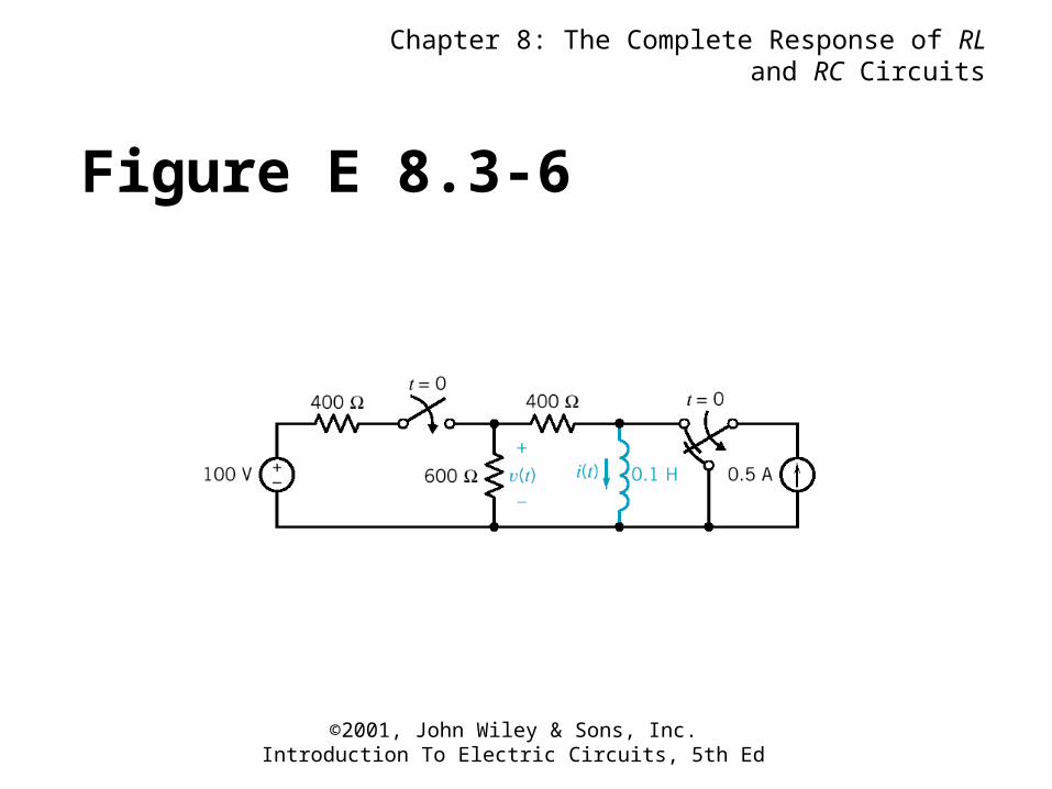
Figure E 8.3-6
Chapter 8: The Complete Response of RL and RC Circuits
©2001, John Wiley & Sons, Inc.Introduction To Electric Circuits, 5th Ed
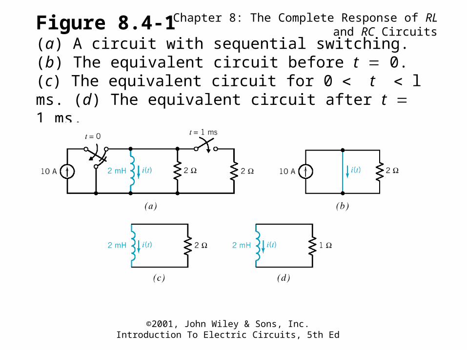
Figure 8.4-1(a) A circuit with sequential switching. (b) The equivalent circuit before t 0. (c) The equivalent circuit for 0 t l ms. (d) The equivalent circuit after t 1 ms.
Chapter 8: The Complete Response of RL and RC Circuits
©2001, John Wiley & Sons, Inc.Introduction To Electric Circuits, 5th Ed
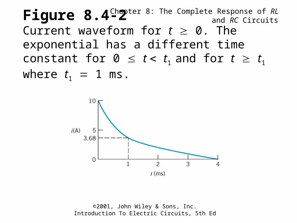
Figure 8.4-2Current waveform for t 0. The exponential has a different time constant for 0 t t1 and for t t1 where t1 1 ms.
Chapter 8: The Complete Response of RL and RC Circuits
©2001, John Wiley & Sons, Inc.Introduction To Electric Circuits, 5th Ed
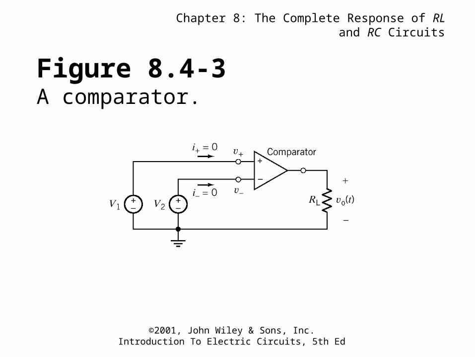
Figure 8.4-3A comparator.
Chapter 8: The Complete Response of RL and RC Circuits
©2001, John Wiley & Sons, Inc.Introduction To Electric Circuits, 5th Ed
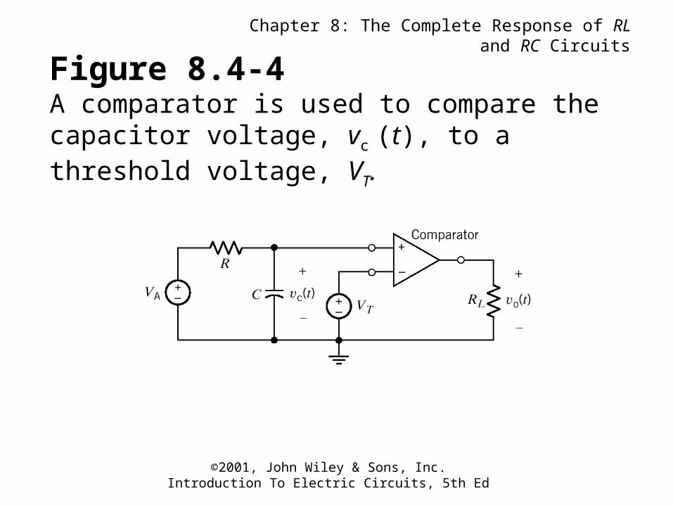
Figure 8.4-4A comparator is used to compare the capacitor voltage, vc (t), to a threshold voltage, VT.
Chapter 8: The Complete Response of RL and RC Circuits
©2001, John Wiley & Sons, Inc.Introduction To Electric Circuits, 5th Ed
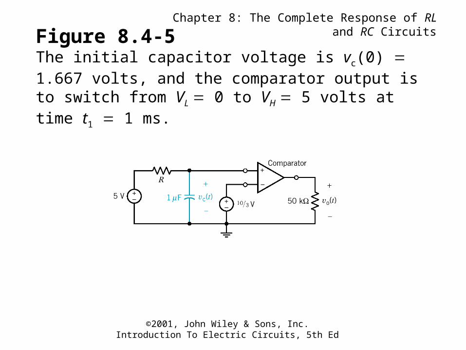
Figure 8.4-5The initial capacitor voltage is vc(0) 1.667 volts, and the comparator output is to switch from VL 0 to VH 5 volts at time t1 1 ms.
Chapter 8: The Complete Response of RL and RC Circuits
©2001, John Wiley & Sons, Inc.Introduction To Electric Circuits, 5th Ed
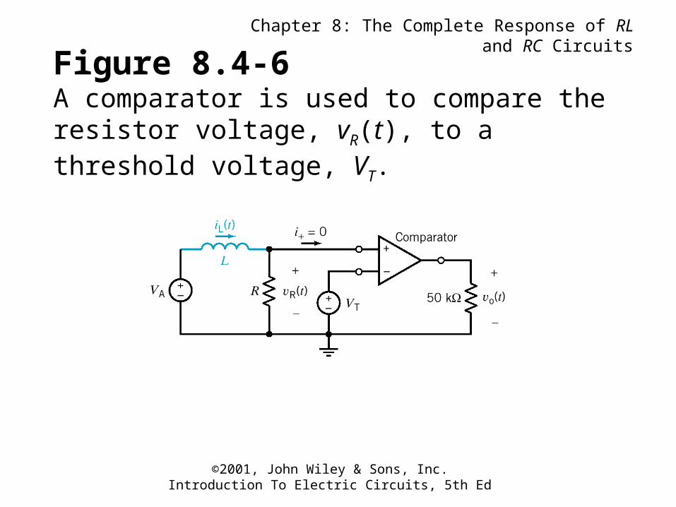
Figure 8.4-6A comparator is used to compare the resistor voltage, vR(t), to a threshold voltage, VT.
Chapter 8: The Complete Response of RL and RC Circuits
©2001, John Wiley & Sons, Inc.Introduction To Electric Circuits, 5th Ed
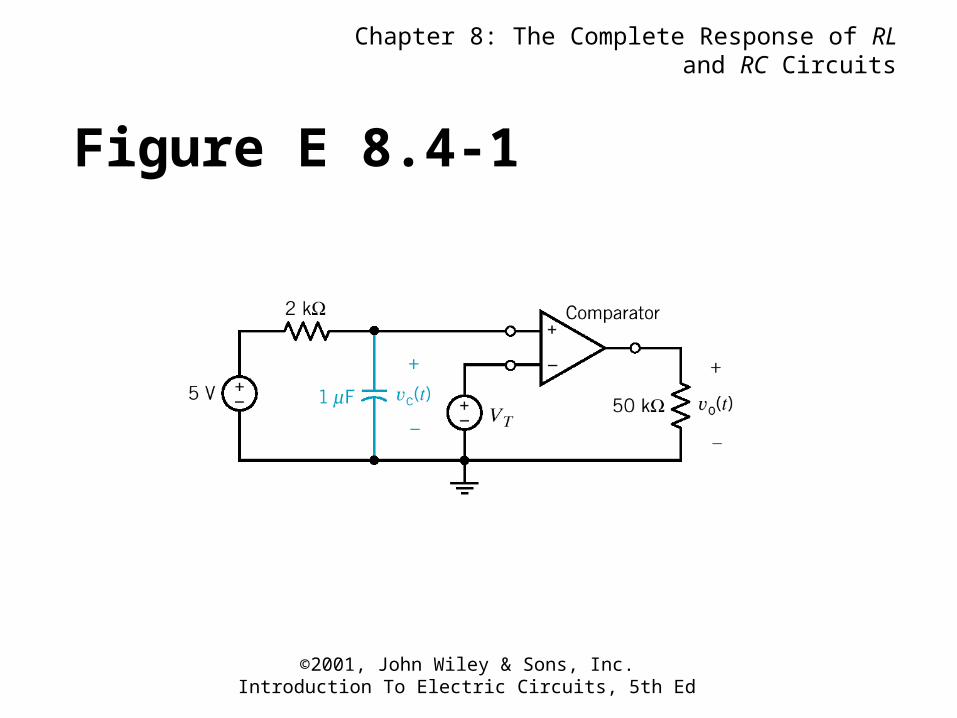
Figure E 8.4-1
Chapter 8: The Complete Response of RL and RC Circuits
©2001, John Wiley & Sons, Inc.Introduction To Electric Circuits, 5th Ed
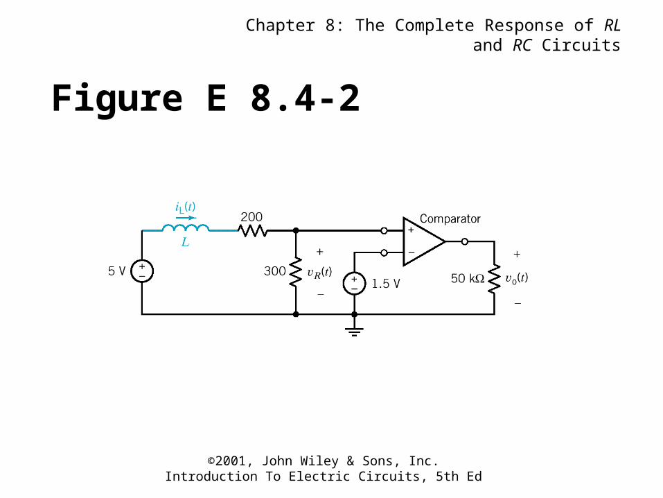
Figure E 8.4-2
Chapter 8: The Complete Response of RL and RC Circuits
©2001, John Wiley & Sons, Inc.Introduction To Electric Circuits, 5th Ed
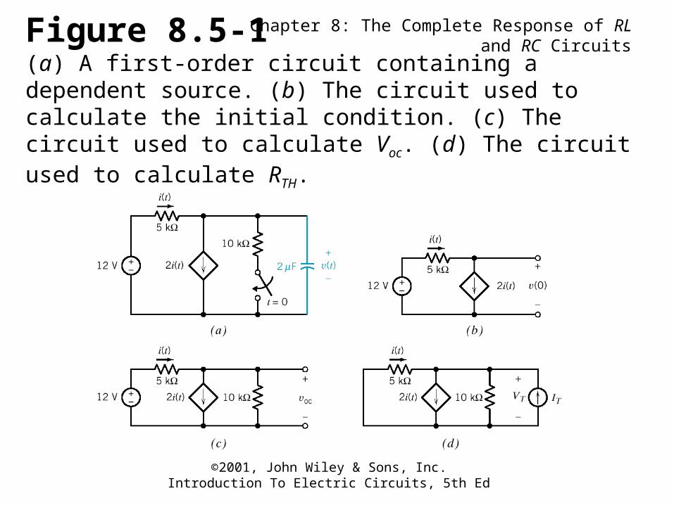
Figure 8.5-1(a) A first-order circuit containing a dependent source. (b) The circuit used to calculate the initial condition. (c) The circuit used to calculate Voc. (d) The circuit used to calculate RTH.
Chapter 8: The Complete Response of RL and RC Circuits
©2001, John Wiley & Sons, Inc.Introduction To Electric Circuits, 5th Ed
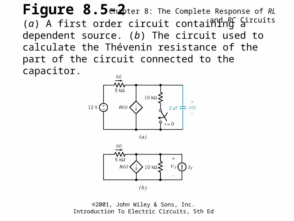
Figure 8.5-2(a) A first order circuit containing a dependent source. (b) The circuit used to calculate the Thévenin resistance of the part of the circuit connected to the capacitor.
Chapter 8: The Complete Response of RL and RC Circuits
©2001, John Wiley & Sons, Inc.Introduction To Electric Circuits, 5th Ed
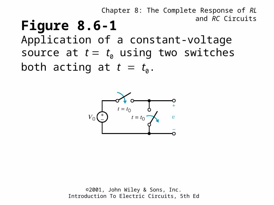
Figure 8.6-1Application of a constant-voltage source at t t0 using two switches both acting at t t0.
Chapter 8: The Complete Response of RL and RC Circuits
©2001, John Wiley & Sons, Inc.Introduction To Electric Circuits, 5th Ed
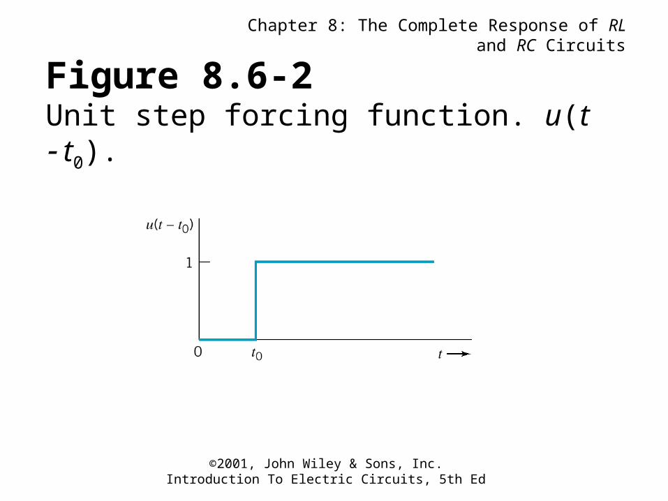
Figure 8.6-2Unit step forcing function. u(t t0).
Chapter 8: The Complete Response of RL and RC Circuits
©2001, John Wiley & Sons, Inc.Introduction To Electric Circuits, 5th Ed
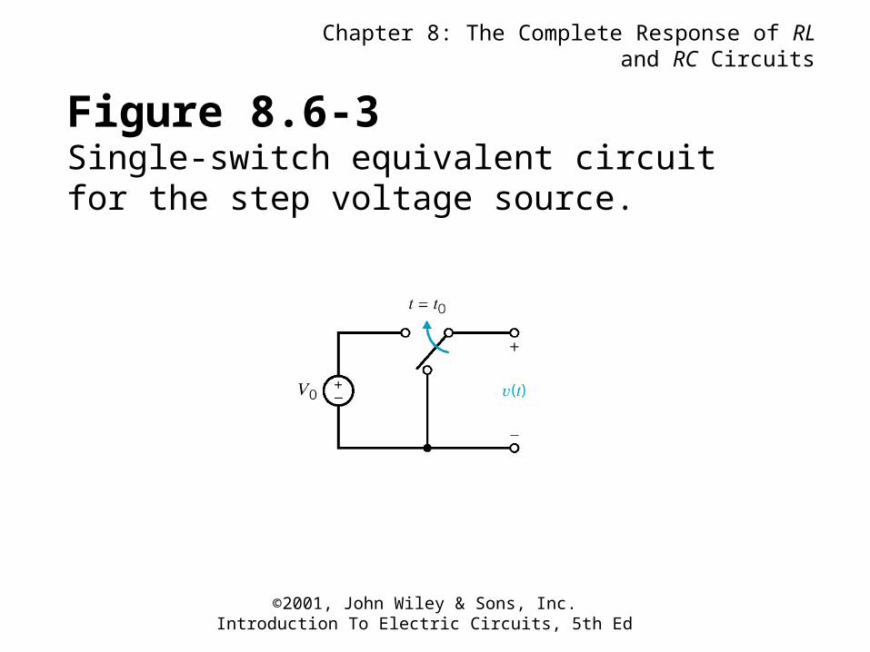
Figure 8.6-3Single-switch equivalent circuit for the step voltage source.
Chapter 8: The Complete Response of RL and RC Circuits
©2001, John Wiley & Sons, Inc.Introduction To Electric Circuits, 5th Ed
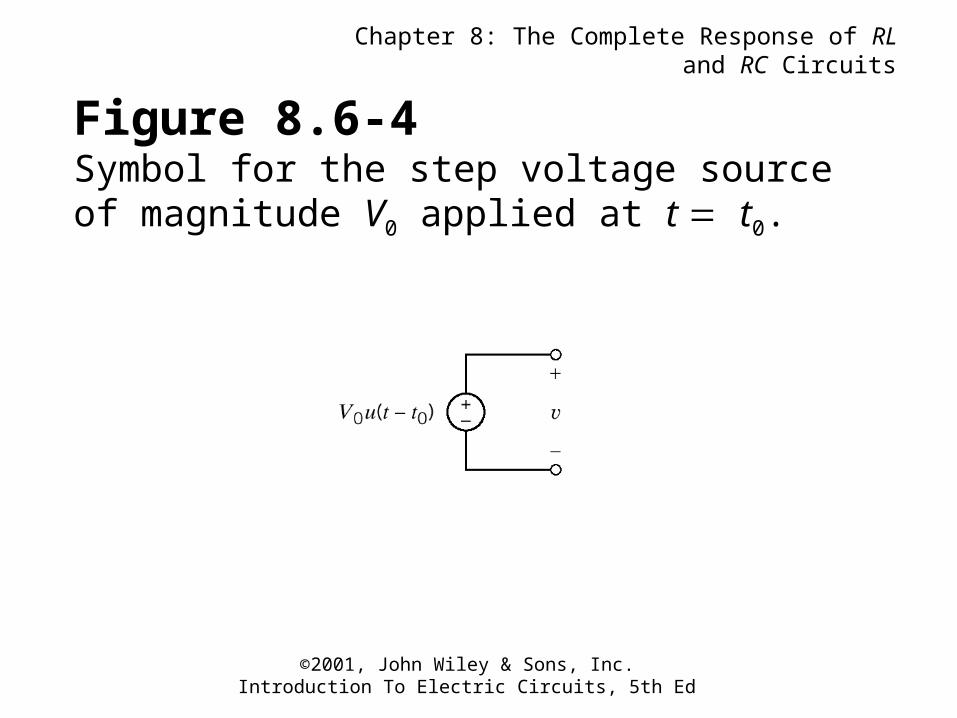
Figure 8.6-4Symbol for the step voltage source of magnitude V0 applied at t t0.
Chapter 8: The Complete Response of RL and RC Circuits
©2001, John Wiley & Sons, Inc.Introduction To Electric Circuits, 5th Ed
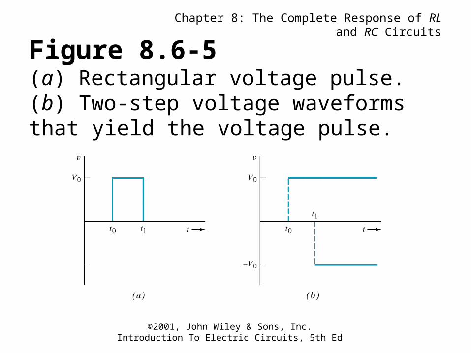
Figure 8.6-5(a) Rectangular voltage pulse. (b) Two-step voltage waveforms that yield the voltage pulse.
Chapter 8: The Complete Response of RL and RC Circuits
©2001, John Wiley & Sons, Inc.Introduction To Electric Circuits, 5th Ed
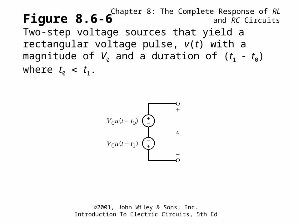
Figure 8.6-6Two-step voltage sources that yield a rectangular voltage pulse, v(t) with a magnitude of V0 and a duration of (t1 t0) where t0 t1.
Chapter 8: The Complete Response of RL and RC Circuits
©2001, John Wiley & Sons, Inc.Introduction To Electric Circuits, 5th Ed
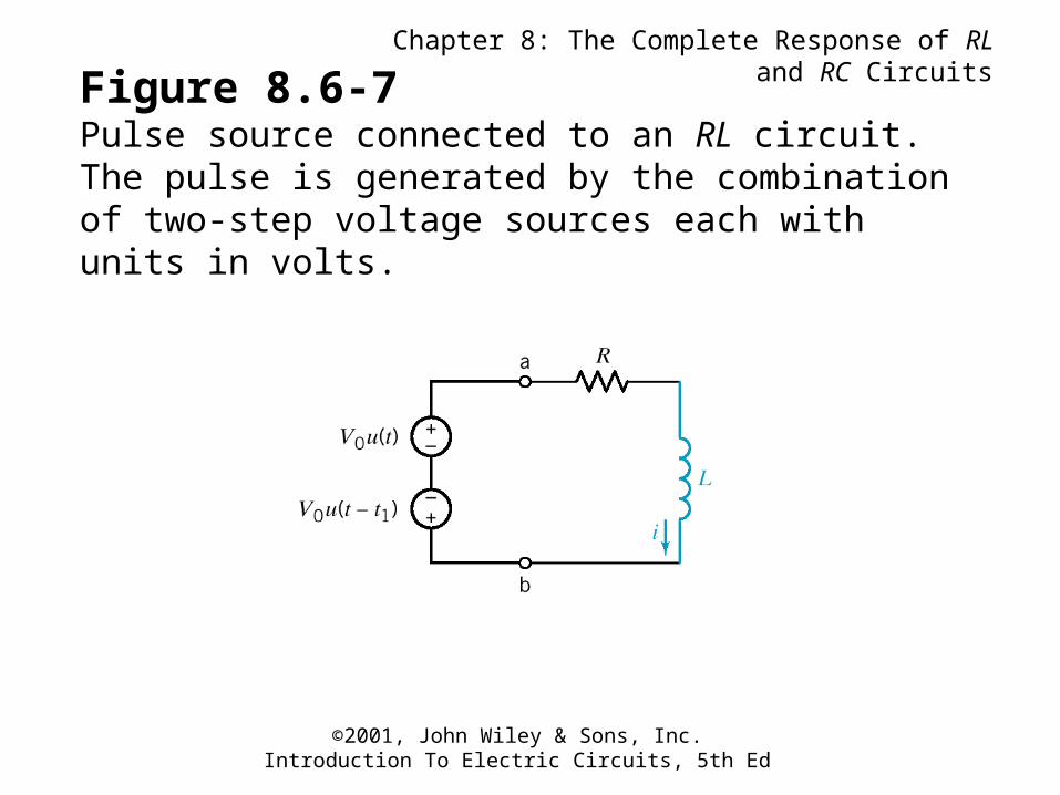
Figure 8.6-7Pulse source connected to an RL circuit. The pulse is generated by the combination of two-step voltage sources each with units in volts.
Chapter 8: The Complete Response of RL and RC Circuits
©2001, John Wiley & Sons, Inc.Introduction To Electric Circuits, 5th Ed
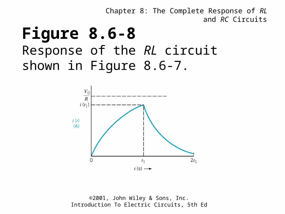
Figure 8.6-8Response of the RL circuit shown in Figure 8.6-7.
Chapter 8: The Complete Response of RL and RC Circuits
©2001, John Wiley & Sons, Inc.Introduction To Electric Circuits, 5th Ed
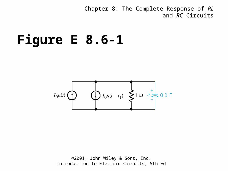
Figure E 8.6-1
Chapter 8: The Complete Response of RL and RC Circuits
©2001, John Wiley & Sons, Inc.Introduction To Electric Circuits, 5th Ed
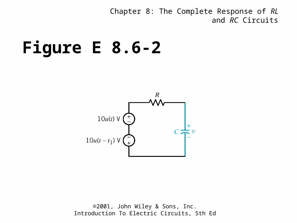
Figure E 8.6-2
Chapter 8: The Complete Response of RL and RC Circuits
©2001, John Wiley & Sons, Inc.Introduction To Electric Circuits, 5th Ed
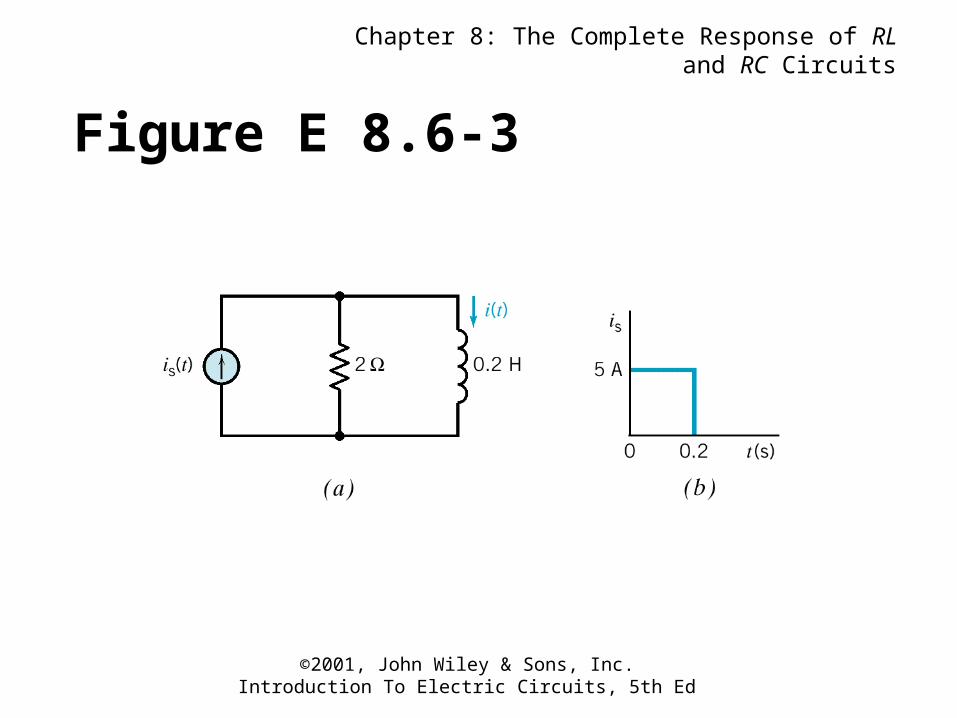
Figure E 8.6-3
Chapter 8: The Complete Response of RL and RC Circuits
©2001, John Wiley & Sons, Inc.Introduction To Electric Circuits, 5th Ed
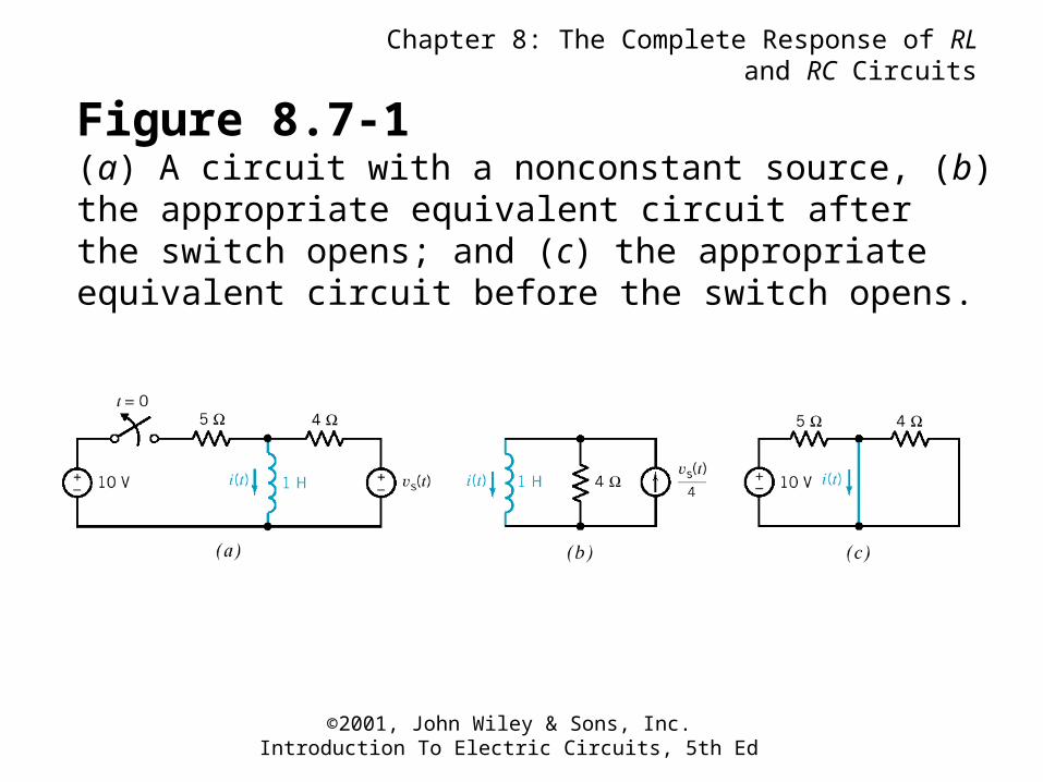
Figure 8.7-1(a) A circuit with a nonconstant source, (b) the appropriate equivalent circuit after the switch opens; and (c) the appropriate equivalent circuit before the switch opens.
Chapter 8: The Complete Response of RL and RC Circuits
©2001, John Wiley & Sons, Inc.Introduction To Electric Circuits, 5th Ed
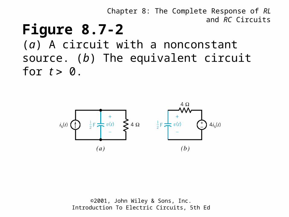
Figure 8.7-2(a) A circuit with a nonconstant source. (b) The equivalent circuit for t 0.
Chapter 8: The Complete Response of RL and RC Circuits
©2001, John Wiley & Sons, Inc.Introduction To Electric Circuits, 5th Ed
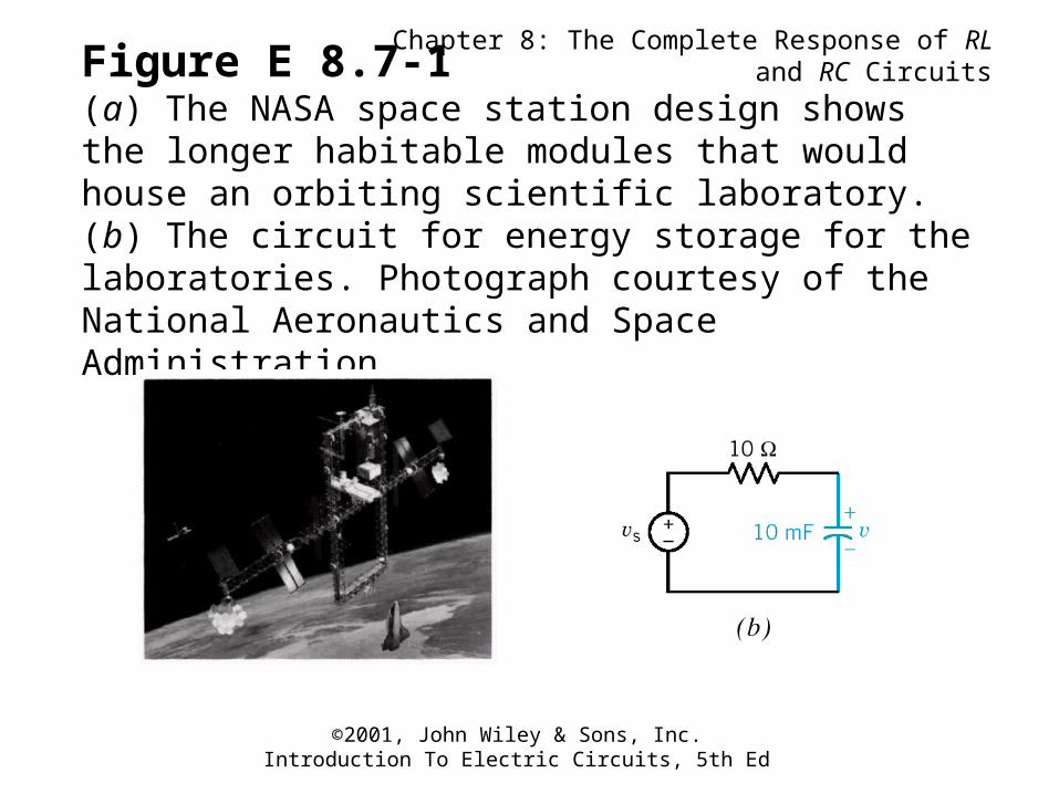
Figure E 8.7-1(a) The NASA space station design shows the longer habitable modules that would house an orbiting scientific laboratory. (b) The circuit for energy storage for the laboratories. Photograph courtesy of the National Aeronautics and Space Administration.
Chapter 8: The Complete Response of RL and RC Circuits
©2001, John Wiley & Sons, Inc.Introduction To Electric Circuits, 5th Ed
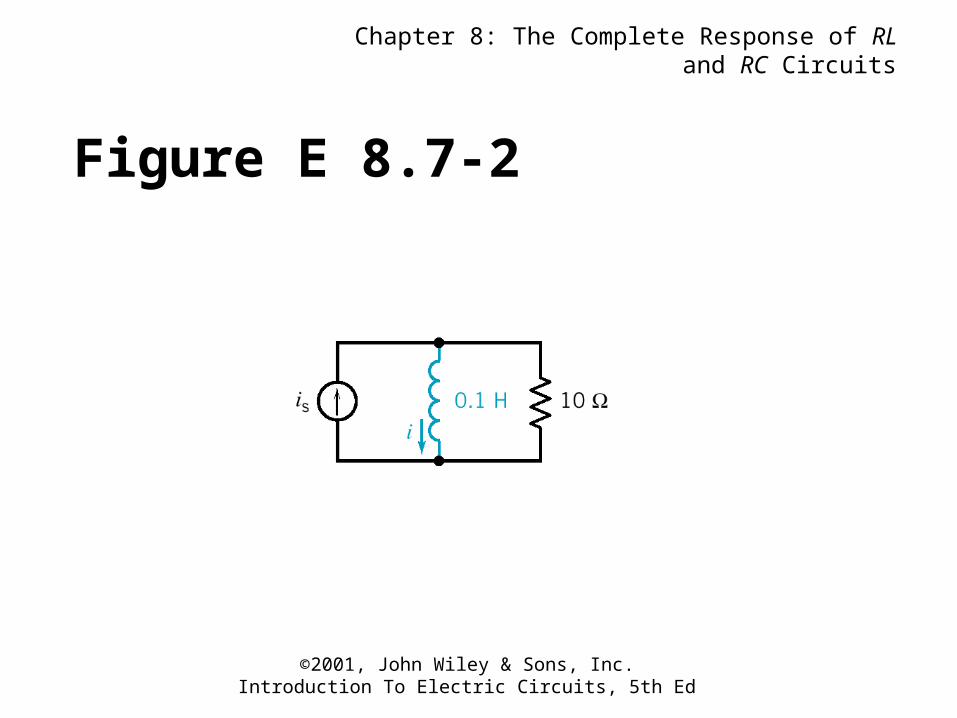
Figure E 8.7-2
Chapter 8: The Complete Response of RL and RC Circuits
©2001, John Wiley & Sons, Inc.Introduction To Electric Circuits, 5th Ed
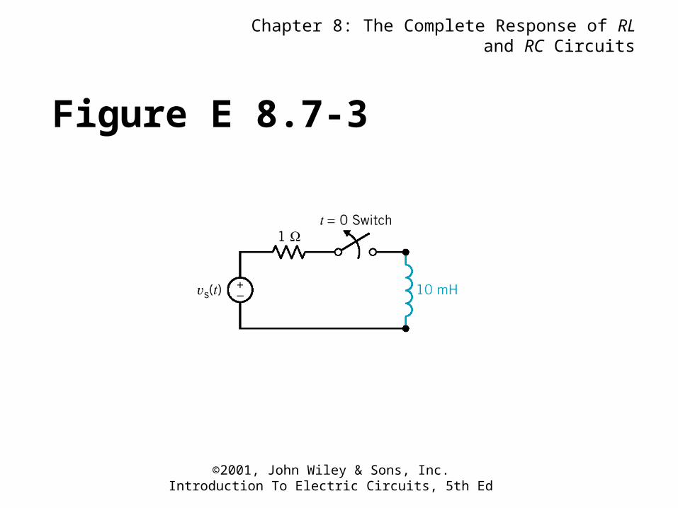
Figure E 8.7-3
Chapter 8: The Complete Response of RL and RC Circuits
©2001, John Wiley & Sons, Inc.Introduction To Electric Circuits, 5th Ed
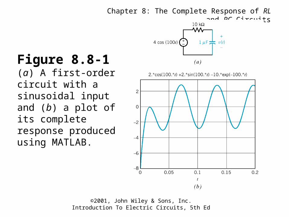
Figure 8.8-1(a) A first-order circuit with a sinusoidal input and (b) a plot of its complete response produced using MATLAB.
Chapter 8: The Complete Response of RL and RC Circuits
©2001, John Wiley & Sons, Inc.Introduction To Electric Circuits, 5th Ed
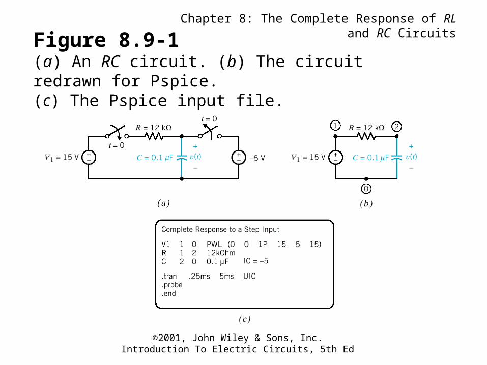
Figure 8.9-1(a) An RC circuit. (b) The circuit redrawn for Pspice. (c) The Pspice input file.
Chapter 8: The Complete Response of RL and RC Circuits
©2001, John Wiley & Sons, Inc.Introduction To Electric Circuits, 5th Ed
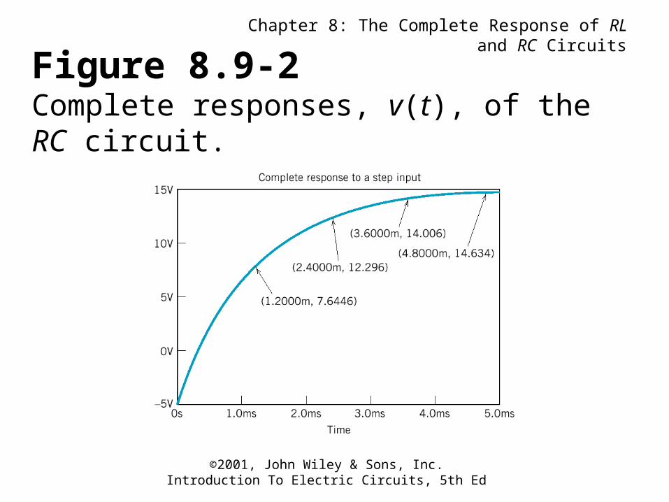
Figure 8.9-2Complete responses, v(t), of the RC circuit.
Chapter 8: The Complete Response of RL and RC Circuits
©2001, John Wiley & Sons, Inc.Introduction To Electric Circuits, 5th Ed
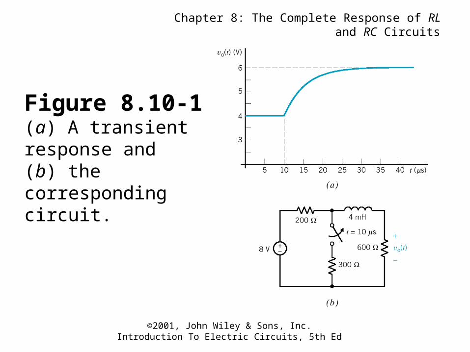
Figure 8.10-1(a) A transient response and (b) the corresponding circuit.
Chapter 8: The Complete Response of RL and RC Circuits
©2001, John Wiley & Sons, Inc.Introduction To Electric Circuits, 5th Ed
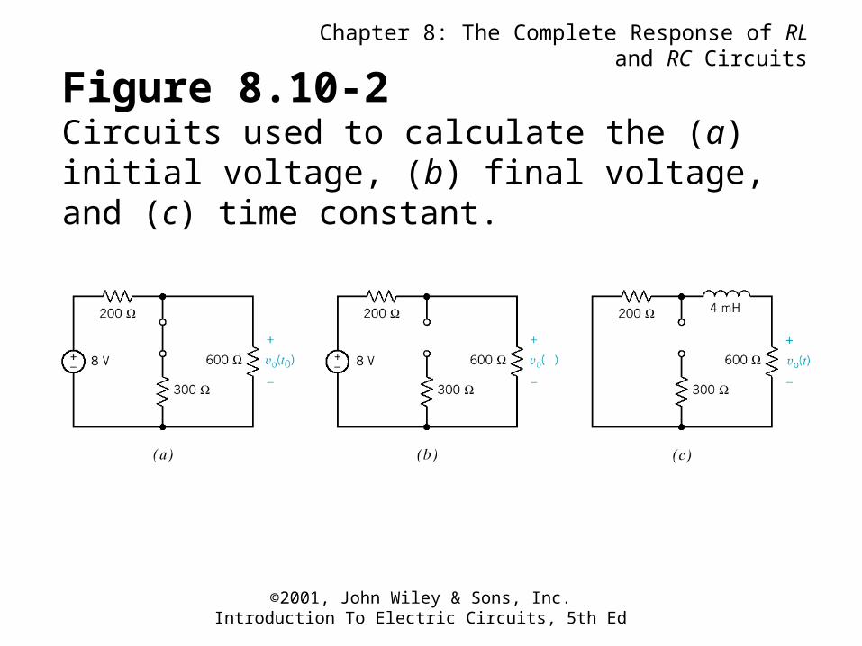
Figure 8.10-2Circuits used to calculate the (a) initial voltage, (b) final voltage, and (c) time constant.
Chapter 8: The Complete Response of RL and RC Circuits
©2001, John Wiley & Sons, Inc.Introduction To Electric Circuits, 5th Ed
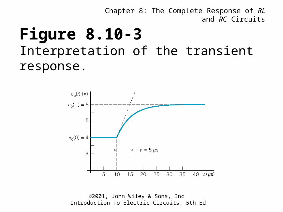
Figure 8.10-3Interpretation of the transient response.
Chapter 8: The Complete Response of RL and RC Circuits
©2001, John Wiley & Sons, Inc.Introduction To Electric Circuits, 5th Ed
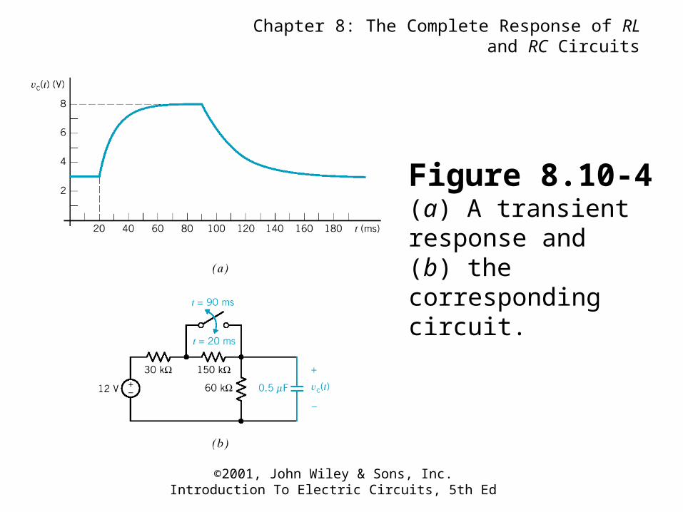
Figure 8.10-4(a) A transient response and (b) the corresponding circuit.
Chapter 8: The Complete Response of RL and RC Circuits
©2001, John Wiley & Sons, Inc.Introduction To Electric Circuits, 5th Ed
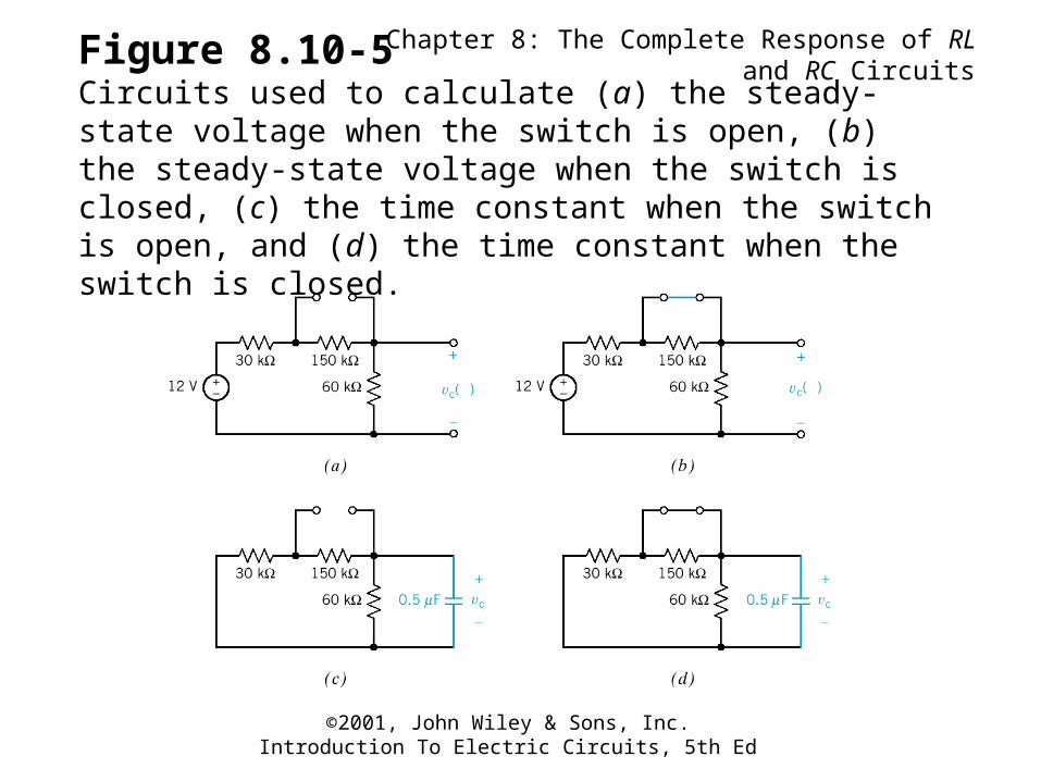
Figure 8.10-5Circuits used to calculate (a) the steady-state voltage when the switch is open, (b) the steady-state voltage when the switch is closed, (c) the time constant when the switch is open, and (d) the time constant when the switch is closed.
Chapter 8: The Complete Response of RL and RC Circuits
©2001, John Wiley & Sons, Inc.Introduction To Electric Circuits, 5th Ed
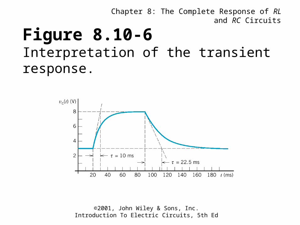
Figure 8.10-6Interpretation of the transient response.
Chapter 8: The Complete Response of RL and RC Circuits
©2001, John Wiley & Sons, Inc.Introduction To Electric Circuits, 5th Ed
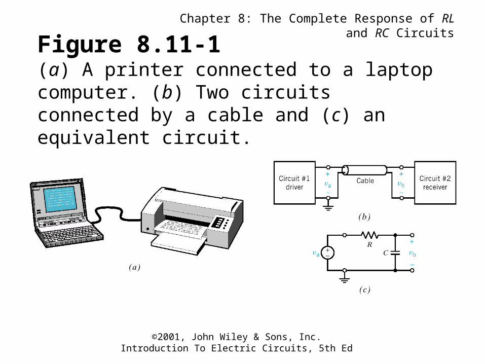
Figure 8.11-1(a) A printer connected to a laptop computer. (b) Two circuits connected by a cable and (c) an equivalent circuit.
Chapter 8: The Complete Response of RL and RC Circuits
©2001, John Wiley & Sons, Inc.Introduction To Electric Circuits, 5th Ed
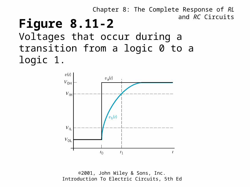
Figure 8.11-2Voltages that occur during a transition from a logic 0 to a logic 1.