Embed Size (px)
Citation preview

The term meelectronics, in integratiomechanical such mechamechanics, tures, the melectrical anestimates areemerging smprovided for
8.1 Fu
Statics an
The fundamsystem cons
product of t
The consemomentum
Eniko T. E
University of
0066_Frame_C08 Page 1 Wednesday, January 9, 2002 3:48 PM
©2002 CRC P
8Structures and Materials
8.1 Fundamental Laws of MechanicsStatics and Dynamics of Mechatronic Systems • Equationsof Motion of Deformable Bodies • Electric Phenomena
8.2 Common Structures in Mechatronic Systems Beams • Torsional Springs • Thin Plates
8.3 Vibration and Modal Analysis8.4 Buckling Analysis .8.5 Transducers
Electrostatic Transducers • Electromagnetic Transducers • Thermal Actuators • ElectroactivePolymer Actuators
8.6 Future Trends
chatronics was first used by Japanese engineers to define a mechanical system with embeddedcapable of providing intelligence and control functions. Since then, the continued progressn has led to the development of microelectromechanical systems (MEMS) in which thestructures themselves are part of the electrical subsystem. The development and design oftronic systems requires interdisciplinary knowledge in several disciplines—electronics,
materials, and chemistry. This section contains an overview of the main mechanical struc-aterials they are built from, and the governing laws describing the interaction between
d mechanical processes. It is intended for use in the initial stage of the design, when quick necessary to validate or reject a particular concept. Special attention is devoted to the newlyart materials—electroactive polymer actuators. Several tables of material constants are also reference.
ndamental Laws of Mechanics
d Dynamics of Mechatronic Systems
ental laws of mechanics are the balance of linear and angular momentum. For an idealizedisting of a point mass m moving with velocity v, the linear momentum is defined as thehe mass and the velocity:
L = mv (8.1)
rvation of linear momentum for a single particle postulates that the rate of change of linear is equal to the sum of all forces acting on the particle
(8.2)L mv Fi∑= =
nikovArizona
ress LLC
where we hawith respect
where
r
OP
is t
for a single iparticles (a defined as th
The seconis equal to t
where
M
i
ar
chosen to b
simpler form
where ωωωω
is t
of mass. Equof rigid bod
problem
. Coand (8.7) incthan the elethe applicati
Equation
Rigid bodiesthey are madforces. Whe
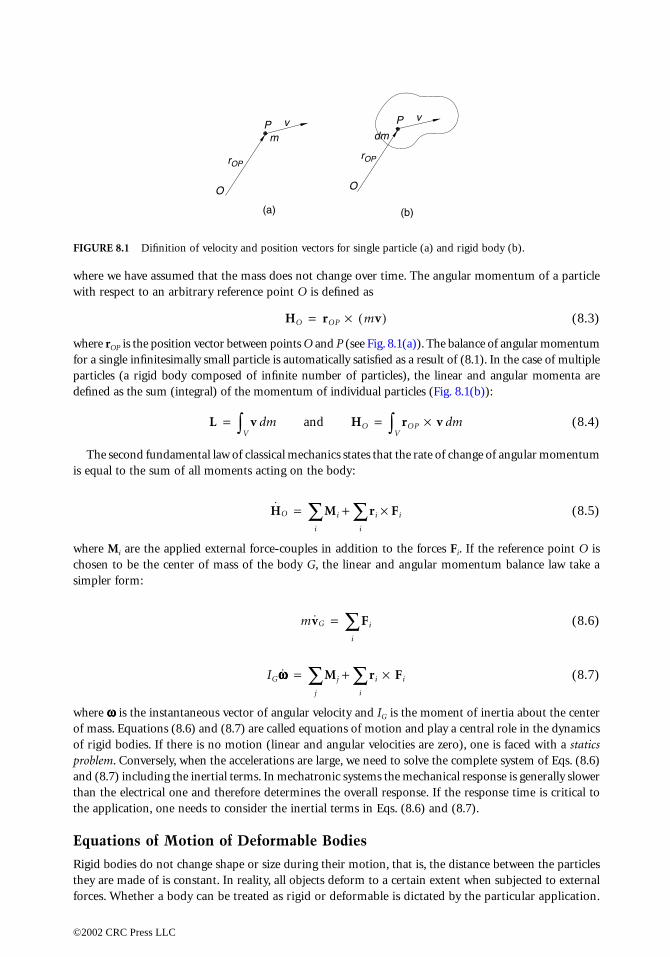
FIGURE 8.1
P v
0066_Frame_C08 Page 2 Wednesday, January 9, 2002 3:48 PM
©2002 CRC P
ve assumed that the mass does not change over time. The angular momentum of a particle to an arbitrary reference point O is defined as
(8.3)
he position vector between points O and P (see Fig. 8.1(a)). The balance of angular momentumnfinitesimally small particle is automatically satisfied as a result of (8.1). In the case of multiplerigid body composed of infinite number of particles), the linear and angular momenta aree sum (integral) of the momentum of individual particles (Fig. 8.1(b)):
(8.4)
d fundamental law of classical mechanics states that the rate of change of angular momentumhe sum of all moments acting on the body:
(8.5)
e the applied external force-couples in addition to the forces Fi. If the reference point O ise the center of mass of the body G, the linear and angular momentum balance law take a
:
(8.6)
(8.7)
he instantaneous vector of angular velocity and IG is the moment of inertia about the centerations (8.6) and (8.7) are called equations of motion and play a central role in the dynamicsies. If there is no motion (linear and angular velocities are zero), one is faced with a staticsnversely, when the accelerations are large, we need to solve the complete system of Eqs. (8.6)luding the inertial terms. In mechatronic systems the mechanical response is generally slower
ctrical one and therefore determines the overall response. If the response time is critical toon, one needs to consider the inertial terms in Eqs. (8.6) and (8.7).
s of Motion of Deformable Bodies
do not change shape or size during their motion, that is, the distance between the particlese of is constant. In reality, all objects deform to a certain extent when subjected to external
ther a body can be treated as rigid or deformable is dictated by the particular application.
Difinition of velocity and position vectors for single particle (a) and rigid body (b).
OO
P
rOPrOP
mv
(a) (b)
dm
HO rOP mv( )×=
L v m and HOdV∫ rOP v× md
V∫= =
HO Mi ri
i
∑ Fi×+i
∑=
mvG Fi
i
∑=
IGωωωω Mj ri Fi×i
∑+j
∑=
ress LLC
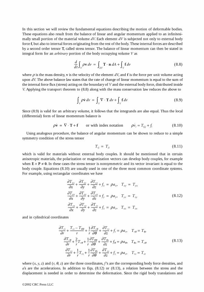
In this section we will review the fundamental equations describing the motion of deformable bodies.These equations also result from the balance of linear and angular momentum applied to an infinitesi-mally small
force
f
, but aby a second
integral form
where
ρ
is th
upon
dV
. Ththe internal
V
. Applying
Since (8.9) i(differential
Using anasymmetry co
which is vaanisotropic when
E
×
P
body coupleFor example
and in cylin
where (
x
,
y
,
a’
s are the adisplacemen
0066_Frame_C08 Page 3 Wednesday, January 9, 2002 3:48 PM
©2002 CRC P
portion of the material volume dV. Each element dV is subjected not only to external bodylso to internal forces originating from the rest of the body. These internal forces are describedorder tensor T, called stress tensor. The balance of linear momentum can then be stated in for an arbitrary portion of the body occupying volume V as
(8.8)
e mass density, v is the velocity of the element dV, and f is the force per unit volume actinge above balance law states that the rate of change of linear momentum is equal to the sum offorce flux (stress) acting on the boundary of V and the external body force, distributed insidethe transport theorem to (8.8) along with the mass conservation law reduces the above to
(8.9)
s valid for an arbitrary volume, it follows that the integrands are also equal. Thus the local) form of linear momentum balance is
or with index notation ρ i = Tij,j + fi (8.10)
logous procedure, the balance of angular momentum can be shown to reduce to a simplendition of the stress tensor
(8.11)
lid for materials without external body couples. It should be mentioned that in certainmaterials, the polarization or magnetization vectors can develop body couples, for example≠ 0. In these cases the stress tensor is nonsymmetric and its vector invariant is equal to the. Equations (8.10) are usually used in one of the three most common coordinate systems., using rectangular coordinates we have
(8.12)
drical coordinates
(8.13)
z) and (r, θ, z) are the three coordinates, f ’s are the corresponding body force densities, andccelerations. In addition to Eqs. (8.12) or (8.13), a relation between the stress and thet is needed in order to determine the deformation. Since the rigid body translations and
ddt----- rv vd
V∫ T n⋅ A f vdV∫+d
∂V∫=
rv vdV∫ ∇ T⋅ v f vd
V∫+dV∫=
rv ∇ T f+⋅= v
Tij Tji=
∂Txx
∂x----------
∂Txy
∂y----------
∂Txz
∂z---------- fx+ + + rax, Txy Tyx= =
∂Tyx
∂x----------
∂Tyy
∂y----------
∂Tyz
∂z---------- fy+ + + ray, Tyz Tzy= =
∂Tzx
∂x----------
∂Tzy
∂y----------
∂Tzz
∂z---------- fz+ + + raz, Txz Tzx= =
∂Trr
∂r----------
Trr Tq q–r
-------------------- 1r--
∂Trq
∂q----------
∂Trz
∂z---------- fr++ + + rar,= Trq Tqr=
∂Trq
∂r---------- 2
r--Trq
1r--
∂Tq q
∂q-----------
∂Tqz
∂z---------- fq++ + + raq,= Tqz Tzq=
∂Trz
∂r---------- 1
r--Trz
1r--
∂Tqz
∂q----------
∂Tzz
∂z---------- fz++ + + raz,= Trz Tzr=
ress LLC
rotations do not cause deformation of the body, they do not affect the internal stress field either. In fact,the latter is a function of the gradient of the displacement, called deformation gradient. When thisgradient is s
The consematerial. Colinear elastic
In the mostsymmetry, tstructural mconstants:
If the materis further redused materi
Additiona
ex
∂u∂x------=
0066_Frame_C08 Page 4 Wednesday, January 9, 2002 3:48 PM
©2002 CRC P
mall, a linear relationship between the displacements and strains can be used
(8.14)
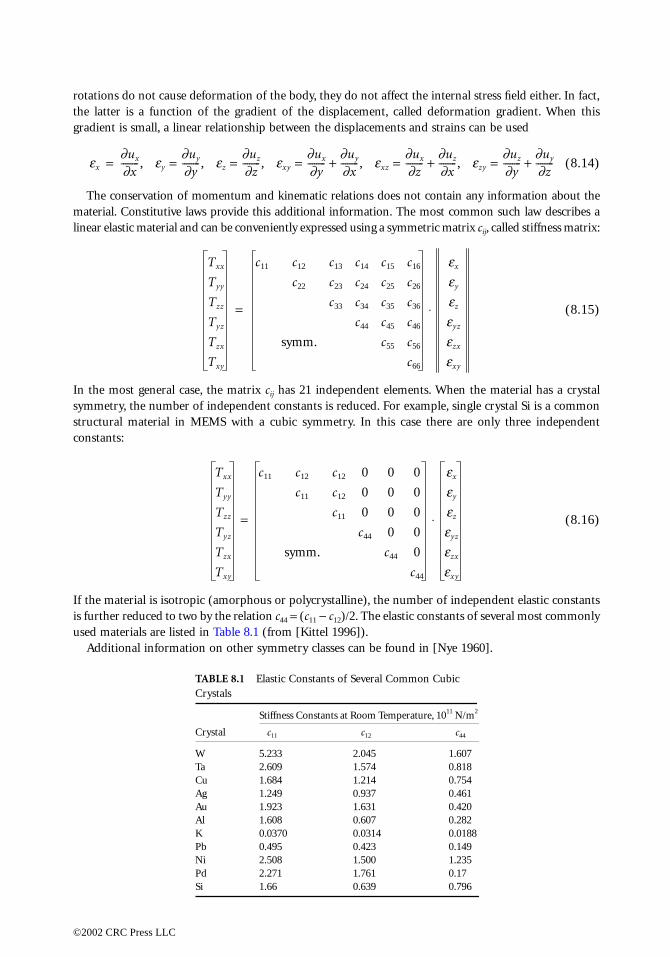
rvation of momentum and kinematic relations does not contain any information about thenstitutive laws provide this additional information. The most common such law describes a material and can be conveniently expressed using a symmetric matrix cij, called stiffness matrix:
(8.15)
general case, the matrix cij has 21 independent elements. When the material has a crystalhe number of independent constants is reduced. For example, single crystal Si is a commonaterial in MEMS with a cubic symmetry. In this case there are only three independent
(8.16)
ial is isotropic (amorphous or polycrystalline), the number of independent elastic constantsuced to two by the relation c44 = (c11 − c12)/2. The elastic constants of several most commonly
als are listed in Table 8.1 (from [Kittel 1996]).l information on other symmetry classes can be found in [Nye 1960].
TABLE 8.1 Elastic Constants of Several Common Cubic Crystals
Stiffness Constants at Room Temperature, 1011 N/m2
Crystal c11 c12 c44
W 5.233 2.045 1.607Ta 2.609 1.574 0.818Cu 1.684 1.214 0.754Ag 1.249 0.937 0.461Au 1.923 1.631 0.420Al 1.608 0.607 0.282K 0.0370 0.0314 0.0188Pb 0.495 0.423 0.149Ni 2.508 1.500 1.235Pd 2.271 1.761 0.17Si 1.66 0.639 0.796
x-- , ey
∂uy
∂y-------- , ez
∂uz
∂z-------- , exy
∂ux
∂y--------
∂uy
∂x-------- , exz
∂ux
∂z--------
∂uz
∂x-------- , ezy
∂uz
∂y--------
∂uy
∂z--------+=+=+===
Txx
Tyy
Tzz
Tyz
Tzx
Txy
c11 c12 c13 c14 c15 c16
c22 c23 c24 c25 c26
c33 c34 c35 c36
c44 c45 c46
symm. c55 c56
c66
ex
ey
ez
eyz
ezx
exy
⋅=
Txx
Tyy
Tzz
Tyz
Tzx
Txy
=
c11 c12 c12 0 0 0
c11 c12 0 0 0
c11 0 0 0
c44 0 0
symm. c44 0
c44
ex
ey
ez
eyz
ezx
exy
⋅
ress LLC
Electric Phenomena
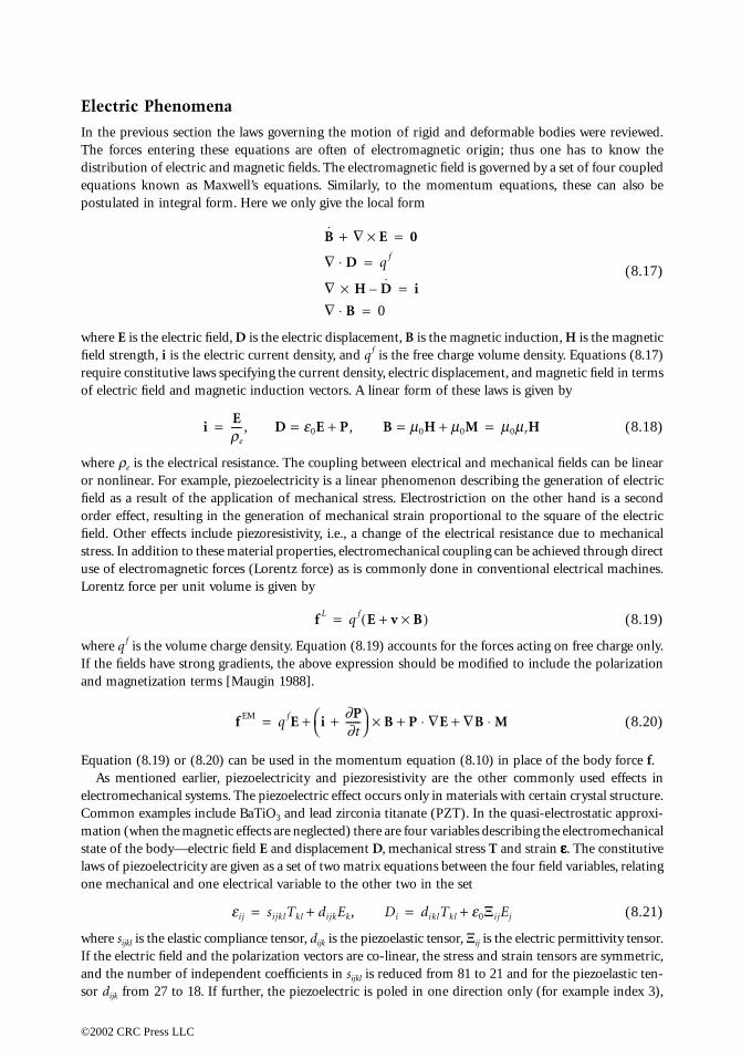
In the previous section the laws governing the motion of rigid and deformable bodies were reviewed.The forces distributionequations kpostulated in
where E is thfield strengtrequire consof electric fi
where ρe is tor nonlinearfield as a reorder effect,field. Other stress. In adduse of electrLorentz forc
where q f is tIf the fields and magnet
Equation (8As menti
electromechCommon exmation (whestate of the blaws of piezoone mechan
where sijkl is tIf the electriand the numsor dijk from
0066_Frame_C08 Page 5 Wednesday, January 9, 2002 3:48 PM
©2002 CRC P
entering these equations are often of electromagnetic origin; thus one has to know the of electric and magnetic fields. The electromagnetic field is governed by a set of four couplednown as Maxwell’s equations. Similarly, to the momentum equations, these can also be integral form. Here we only give the local form
(8.17)
e electric field, D is the electric displacement, B is the magnetic induction, H is the magnetich, i is the electric current density, and qf is the free charge volume density. Equations (8.17)titutive laws specifying the current density, electric displacement, and magnetic field in termseld and magnetic induction vectors. A linear form of these laws is given by
(8.18)
he electrical resistance. The coupling between electrical and mechanical fields can be linear. For example, piezoelectricity is a linear phenomenon describing the generation of electric
sult of the application of mechanical stress. Electrostriction on the other hand is a second resulting in the generation of mechanical strain proportional to the square of the electriceffects include piezoresistivity, i.e., a change of the electrical resistance due to mechanicalition to these material properties, electromechanical coupling can be achieved through directomagnetic forces (Lorentz force) as is commonly done in conventional electrical machines.e per unit volume is given by
(8.19)
he volume charge density. Equation (8.19) accounts for the forces acting on free charge only.have strong gradients, the above expression should be modified to include the polarizationization terms [Maugin 1988].
(8.20)
.19) or (8.20) can be used in the momentum equation (8.10) in place of the body force f.oned earlier, piezoelectricity and piezoresistivity are the other commonly used effects inanical systems. The piezoelectric effect occurs only in materials with certain crystal structure.amples include BaTiO3 and lead zirconia titanate (PZT). In the quasi-electrostatic approxi-n the magnetic effects are neglected) there are four variables describing the electromechanicalody—electric field E and displacement D, mechanical stress T and strain εεεε. The constitutiveelectricity are given as a set of two matrix equations between the four field variables, relatingical and one electrical variable to the other two in the set
(8.21)
he elastic compliance tensor, dijk is the piezoelastic tensor, Ξij is the electric permittivity tensor.c field and the polarization vectors are co-linear, the stress and strain tensors are symmetric,ber of independent coefficients in sijkl is reduced from 81 to 21 and for the piezoelastic ten-
27 to 18. If further, the piezoelectric is poled in one direction only (for example index 3),
B ∇ E×+ 0=
∇ D⋅ q f=
∇ H D–× i=∇ B⋅ 0=
iE
re
---- , D e0E P+ , B m0H m0M+== m0mrH= =
f L q f E v B×+( )=
f EM q fE i∂P∂t------+
B P ∇E ∇B M⋅+⋅+×+=
eij sijklTkl dijkEk, Di+ diklTkl e0ΞijEj+= =
ress LLC
the only nonzero elements are
Numerical v
8.2 Co
Microelectroof integratedcoils, bridgehigh aspect true three-dcapacitive fothe fundame
Beams
Microcantileprobe microsurface micrtwo-layer cadeflection d
where
are the effecThe effective
FIGURE 8.2
Keff6le
3/(-----------=
0066_Frame_C08 Page 6 Wednesday, January 9, 2002 3:48 PM
©2002 CRC P
alues for the coefficients in (8.22) for bulk BaTiO3 crystals can be found in [Zgonik et al. 1994].
mmon Structures in Mechatronic Systems
mechanical systems (MEMS) traditionally use technology developed for the manufacturing circuits. As a result, the employed mechanical structures are often planar devices—springs,
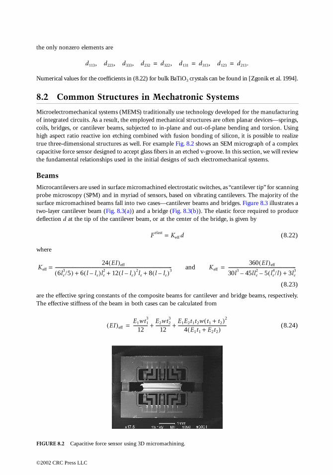
s, or cantilever beams, subjected to in-plane and out-of-plane bending and torsion. Usingratio reactive ion etching combined with fusion bonding of silicon, it is possible to realizeimensional structures as well. For example Fig. 8.2 shows an SEM micrograph of a complexrce sensor designed to accept glass fibers in an etched v-groove. In this section, we will reviewntal relationships used in the initial designs of such electromechanical systems.
vers are used in surface micromachined electrostatic switches, as “cantilever tip” for scanningscopy (SPM) and in myriad of sensors, based on vibrating cantilevers. The majority of theomachined beams fall into two cases—cantilever beams and bridges. Figure 8.3 illustrates antilever beam (Fig. 8.3(a)) and a bridge (Fig. 8.3(b)). The elastic force required to produce at the tip of the cantilever beam, or at the center of the bridge, is given by
F elast = Keff d (8.22)
(8.23)
tive spring constants of the composite beams for cantilever and bridge beams, respectively. stiffness of the beam in both cases can be calculated from
(8.24)
Capacitive force sensor using 3D micromachining.
d113, d223, d333, d232 d322, d131 d313, d123 d213.= = =
24 EI( )eff
5) 6 l le–( )le2 12 l le–( )2le 8 l le–( )3+ + +
----------------------------------------------------------------------------------------------- and Keff
360 EI( )eff
30l3 45l– le2 5 le
4/l( )– 3le3+
-------------------------------------------------------------=
EI( )eff
E1wt13
12-------------
E2wt23
12-------------
E1E2t1t2w t1 t2+( )2
4 E1t1 E2t2+( )--------------------------------------------+ +=
ress LLC
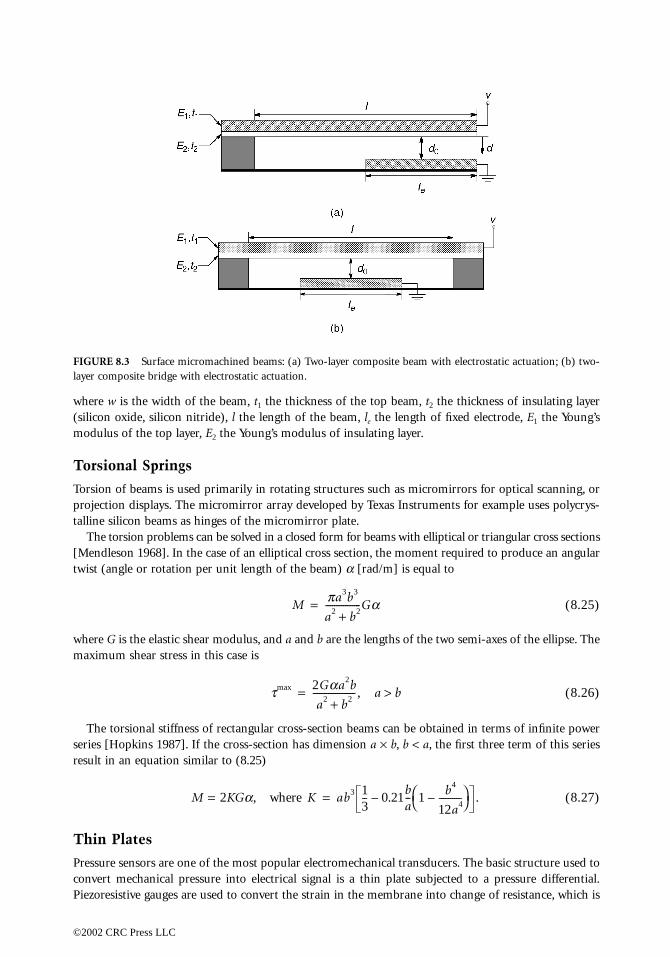
where w is t(silicon oxidmodulus of
Torsional
Torsion of bprojection dtalline silico
The torsio[Mendlesontwist (angle
where G is tmaximum s
The torsioseries [Hopkresult in an
Thin Plat
Pressure senconvert mecPiezoresistiv
FIGURE 8.3layer compos
0066_Frame_C08 Page 7 Wednesday, January 9, 2002 3:48 PM
©2002 CRC P
he width of the beam, t1 the thickness of the top beam, t2 the thickness of insulating layere, silicon nitride), l the length of the beam, le the length of fixed electrode, E1 the Young’sthe top layer, E2 the Young’s modulus of insulating layer.
Springs
eams is used primarily in rotating structures such as micromirrors for optical scanning, orisplays. The micromirror array developed by Texas Instruments for example uses polycrys-n beams as hinges of the micromirror plate. n problems can be solved in a closed form for beams with elliptical or triangular cross sections
1968]. In the case of an elliptical cross section, the moment required to produce an angularor rotation per unit length of the beam) α [rad/m] is equal to
(8.25)
he elastic shear modulus, and a and b are the lengths of the two semi-axes of the ellipse. Thehear stress in this case is
(8.26)
nal stiffness of rectangular cross-section beams can be obtained in terms of infinite powerins 1987]. If the cross-section has dimension a × b, b < a, the first three term of this series
equation similar to (8.25)
M = 2KGα, where (8.27)
es
sors are one of the most popular electromechanical transducers. The basic structure used tohanical pressure into electrical signal is a thin plate subjected to a pressure differential.e gauges are used to convert the strain in the membrane into change of resistance, which is
Surface micromachined beams: (a) Two-layer composite beam with electrostatic actuation; (b) two-ite bridge with electrostatic actuation.
Mpa3b3
a2 b2+----------------Ga=
tmax 2Gaa2b
a2 b2+------------------- , a b>=
K ab3 13-- 0.21
ba-- 1
b4
12a4----------–
– .=
ress LLC

read out usianisotropic subjected tofor w(x, y) i
where D = Eis the thicknstrains are
Using (8.29)in terms of
In the case oare built-in has lateral dthat the madisplacemen
TABLE 8.2 Deflection and Bending Moments of Clamped Plate Under Uniform Load q[Evans 1939]
b/a
11.52∞
FIGURE 8.4
0066_Frame_C08 Page 8 Wednesday, January 9, 2002 3:48 PM
©2002 CRC P
ng a conventional resistive bridge circuit. The initial pressure sensors were fabricated viaetching of silicon, which results in a rectangular diaphragm. Figure 8.4 shows a thin-plate, normal pressure q, resulting in out-of-plane displacement w(x, y). The equilibrium conditions given by the thin plate theory [Timoshenko 1959]:
(8.28)
h3/12(1 − ν 2) is the flexural rigidity, E is the Young’s modulus, ν is the Poisson ratio, and hess of the plate. The edge-moments (moments per unit length of the edge) and the small
(8.29)
, one can calculate the maximum strains occurring at the top and bottom faces of the platethe edge-moments:
(8.30)
f a pressure sensor with a diaphragm subjected to a uniform pressure, the boundary conditionsedges: w = 0, ∂w/∂x = 0 at x = ±a/2 and w = 0, ∂w/∂y = 0 at y = ±b/2, where the diaphragmimensions a × b. The solution of this problem has been obtained by [Evans 1939], showingximum strains are at the center of the edges. The values of the edge-moments and thet of the center of plate are listed in Table 8.2.
W(x = 0, y = 0) Mx(x = a/2, y = 0) My(x = 0, y = b/2) Mx(x = 0, y = 0) My(x = 0, y = 0)
0.00126qa4/D −0.0513qa2 −0.0513qa2 0.0231qa2 0.0231qa2
0.00220qa4/D −0.0757qa2 −0.0570qa2 0.0368qa2 0.0203qa2
0.00254qa4/D −0.0829qa2 −0.0571qa2 0.0412qa2 0.0158qa2
0.00260qa4/D −0.0833qa2 −0.0571qa2 0.0417qa2 0.0125qa2
Thin plate subjected to positive pressure q.
∂ 4w
∂x4--------- 2
∂ 4w
∂x2∂y2---------------- ∂ 4w
∂y4---------+ + q
D---- ,=
Mx x, y( ) D∂ 2w
∂x2--------- n ∂ 2w
∂y2---------–
,–=
My x, y( ) D∂ 2w
∂y2--------- n ∂ 2w
∂x2---------–
,–=
Mxy x, y( ) D(1 n ) ∂ 2w∂x∂y------------– ,=
exx x, y, z( ) z∂ 2w
∂x2---------–=
eyy x, y, z( ) z∂ 2w
∂y2---------–=
exy x, y, z( ) z∂ 2w
∂x∂y------------–=
exxmax x, y, z( ) 12z
Eh3-------- Mx nMy–( ) z=h
12
Eh2-------- Mx nMy–( )= =
eyymax x, y, z( ) 12z
Eh3-------- My nMx–( ) z=h
12
Eh2-------- My nMx–( )= =
ress LLC
8.3 Vibration and Modal Analysis
As mentionwith the accsuperpositionumber (eigmodal analymicro-air-veof a cantilev
where I is thsection. Whthe reduced
where h is thof character
where the ch
The coefficieFor a cantile
Since (8.35)
0066_Frame_C08 Page 9 Wednesday, January 9, 2002 3:48 PM
©2002 CRC P
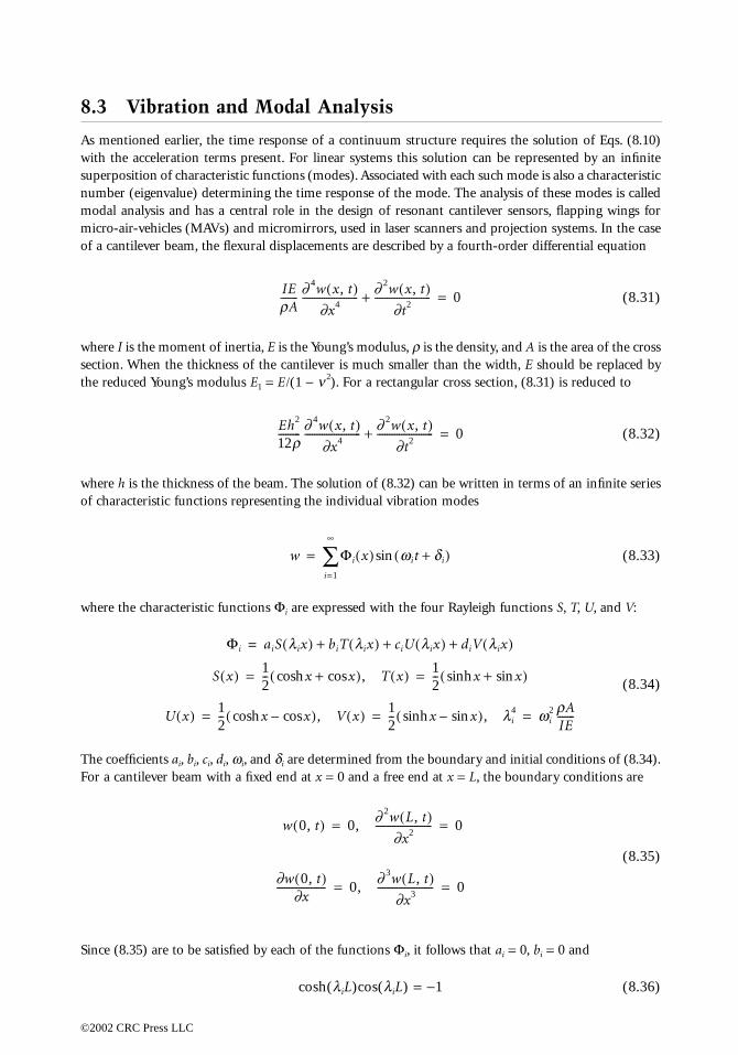
ed earlier, the time response of a continuum structure requires the solution of Eqs. (8.10)eleration terms present. For linear systems this solution can be represented by an infiniten of characteristic functions (modes). Associated with each such mode is also a characteristicenvalue) determining the time response of the mode. The analysis of these modes is calledsis and has a central role in the design of resonant cantilever sensors, flapping wings forhicles (MAVs) and micromirrors, used in laser scanners and projection systems. In the caseer beam, the flexural displacements are described by a fourth-order differential equation
(8.31)
e moment of inertia, E is the Young’s modulus, ρ is the density, and A is the area of the crossen the thickness of the cantilever is much smaller than the width, E should be replaced by Young’s modulus E1 = E/(1 − ν 2). For a rectangular cross section, (8.31) is reduced to
(8.32)
e thickness of the beam. The solution of (8.32) can be written in terms of an infinite seriesistic functions representing the individual vibration modes
(8.33)
aracteristic functions Φi are expressed with the four Rayleigh functions S, T, U, and V:
(8.34)
nts ai, bi, ci, di, ωi, and δi are determined from the boundary and initial conditions of (8.34).ver beam with a fixed end at x = 0 and a free end at x = L, the boundary conditions are
(8.35)
are to be satisfied by each of the functions Φi, it follows that ai = 0, bi = 0 and
cosh(λiL)cos(λiL) = −1 (8.36)
IErA------- ∂ 4w x, t( )
∂x4----------------------- ∂ 2w x, t( )
∂t2-----------------------+ 0=
Eh2
12r--------- ∂ 4w x, t( )
∂x4----------------------- ∂ 2w x, t( )
∂t2-----------------------+ 0=
w Φi x( ) wit di+( )sini=1
∞
∑=
Φi aiS lix( ) biT lix( ) ciU lix( ) diV lix( )+ + +=
S x( ) 12-- x xcos+cosh( ), T x( ) 1
2-- x xsin+sinh( )= =
U x( ) 12-- x xcos–cosh( ), V x( ) 1
2-- x xsin–sinh( ), li
4 wi2 rA
IE-------= = =
w 0, t( ) 0,∂ 2w L, t( )
∂x2----------------------- 0= =
∂w 0, t( )∂x
-------------------- 0,∂ 3w L, t( )
∂x3----------------------- 0= =
ress LLC

From this tr1995].
Figure 8.5analysis is tcantilevers iswith the eneUsing the eqof the tip of
Similar analvibrations o
The inter
8.4 Bu
Structural indue to largeis the scopecross sectionstress of themanufacturiforce will ddeflection. W
FIGURE 8.5
0066_Frame_C08 Page 10 Wednesday, January 9, 2002 3:48 PM
©2002 CRC P
anscendental equation the λi’s and the circular frequencies ωi are determined [Butt et al.
(8.37)
shows the first four vibrational modes of the cantilever. An important result of the modalhe calculation of the amplitude of thermal vibrations of cantilevers. As the size of the reduced to nanometer scale, the energy of random thermal excitations becomes comparablergy of the individual vibration modes. This effect leads to a thermal noise in nanocantilevers.uipartition theorem [Butt et al. 1995] showed that the root mean square of the amplitude such cantilever is
(8.38)
ysis can be performed on vibrations of thin plates such as micromirrors. The free lateralf such a plate are described by
(8.39)
ested reader is referred to [Timoshenko 1959] for further details on vibrations of plates.
ckling Analysis
stability can occur due to material failure, e.g., plastic flow or fracture, or it can also occur changes in the geometry of the structure (e.g., buckling, wrinkling, or collapse). The latter of this section. When short columns are subjected to a compressive load, the stress in the is considered uniform. Thus for short columns, failure will occur when the plastic yield material is reached. In the case of long and slender beams under compression, due tong imperfections, the applied load or the column will have some eccentricity. As a result theevelop a bending moment proportional to the eccentricity, resulting in additional lateral
hile for small loads the lateral displacement will reach equilibrium, above certain critical
First four vibration modes of a cantilever beam.
liL2i 1–( )p
2---------------------- , wi≅ 2i 1–( )2p2
4L2-------------------------- IE
rA-------
2i 1–( )2p2
4L2-------------------------- Eh2
12r---------= =
z2 kTK------
0.64 Å
K--------------- , K
Ewh3
4L2------------= = =
∂ 4w x, y, t( )∂x4
----------------------------- 2∂ 4w x, y, t( )
∂x2∂y2----------------------------- ∂ 4w x, y, t( )
∂y4-----------------------------+ + rh
D------ ∂ 2w x, y, t( )
∂t2-----------------------------–=
ress LLC
load, the bein Fig. 8.5, suto the beam
where the b
From w(L) =out of boun
The above atypes of bea
where severa
8.5 Tra
Transducersmechanical although in capacitive tractuators us
Electrost
The electroscomb electroplate configuteristics canused in elecplate capacit
where A is tdioxide, silicV is the app
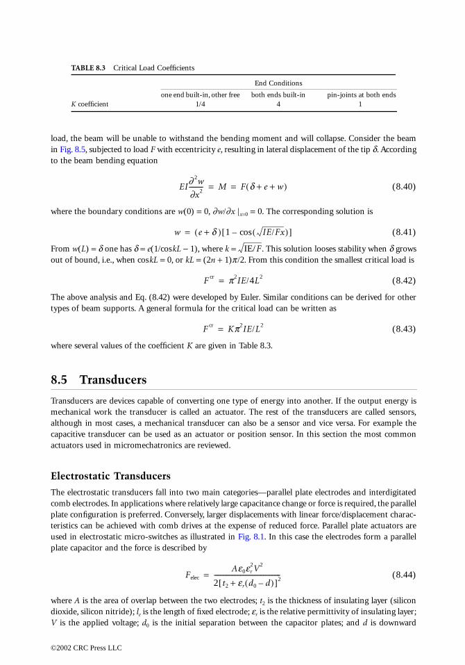
TABLE 8.3 Critical Load Coefficients
End Conditions
K coeffi
0066_Frame_C08 Page 11 Wednesday, January 9, 2002 3:48 PM
©2002 CRC P
am will be unable to withstand the bending moment and will collapse. Consider the beambjected to load F with eccentricity e, resulting in lateral displacement of the tip δ. According
bending equation
(8.40)
oundary conditions are w(0) = 0, ∂w/∂x |x=0 = 0. The corresponding solution is
(8.41)
δ one has δ = e(1/coskL − 1), where k = . This solution looses stability when δ growsd, i.e., when coskL = 0, or kL = (2n + 1)π/2. From this condition the smallest critical load is
(8.42)
nalysis and Eq. (8.42) were developed by Euler. Similar conditions can be derived for otherm supports. A general formula for the critical load can be written as
(8.43)
l val ues of the coefficient K are given in Table 8.3.
nsducers
are devices capable of converting one type of energy into another. If the output energy iswork the transducer is called an actuator. The rest of the transducers are called sensors,most cases, a mechanical transducer can also be a sensor and vice versa. For example theansducer can be used as an actuator or position sensor. In this section the most commoned in micromechatronics are reviewed.
atic Transducers
tatic transducers fall into two main categories—parallel plate electrodes and interdigitateddes. In applications where relatively large capacitance change or force is required, the parallelration is preferred. Conversely, larger displacements with linear force/displacement charac-
be achieved with comb drives at the expense of reduced force. Parallel plate actuators aretrostatic micro-switches as illustrated in Fig. 8.1. In this case the electrodes form a parallelor and the force is described by
(8.44)
he area of overlap between the two electrodes; t2 is the thickness of insulating layer (siliconon nitride); le is the length of fixed electrode; εr is the relative permittivity of insulating layer;lied voltage; d0 is the initial separation between the capacitor plates; and d is downward
one end built-in, other free both ends built-in pin-joints at both endscient 1/4 4 1
EI∂ 2w
∂x2--------- M F d e w+ +( )= =
w e d+( ) 1 IE/Fx( )cos–[ ]=
IE/F
F cr p2IE/4L2=
F cr Kp2IE/L2=
Felec
Ae0er2V2
2 t2 er d0 d–( )+[ ]2-------------------------------------------=
ress LLC
deflection ofas the thresh
where (IE)ef
Comb drin Fig. 8.6(a)a pair of asycase, the forwith respect
where n is ththe most acc[Johnson et
In the transbetween the
Electrom
ElectromagnFig. 8.7. Themagnetic cir
FIGURE 8.6
F el =
0066_Frame_C08 Page 12 Wednesday, January 9, 2002 3:48 PM
©2002 CRC P
the beam. The minimum voltage required to close the gap of a cantilever actuator is knownold voltage [Petersen 1978], and can be approximated as
(8.45)
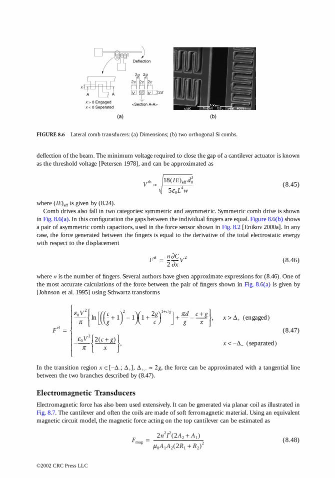
f is given by (8.24). ives also fall in two categories: symmetric and asymmetric. Symmetric comb drive is shown. In this configuration the gaps between the individual fingers are equal. Figure 8.6(b) showsmmetric comb capacitors, used in the force sensor shown in Fig. 8.2 [Enikov 2000a]. In anyce generated between the fingers is equal to the derivative of the total electrostatic energy to the displacement
(8.46)
e number of fingers. Several authors have given approximate expressions for (8.46). One ofurate calculations of the force between the pair of fingers shown in Fig. 8.6(a) is given byal. 1995] using Schwartz transforms
(8.47)
ition region x ∈[−∆−; ∆ +], ∆ +,− ≈ 2g, the force can be approximated with a tangential line two branches described by (8.47).
agnetic Transducers
etic force has also been used extensively. It can be generated via planar coil as illustrated in cantilever and often the coils are made of soft ferromagnetic material. Using an equivalentcuit model, the magnetic force acting on the top cantilever can be estimated as
(8.48)
Lateral comb transducers: (a) Dimensions; (b) two orthogonal Si combs.
VV
Deflection
A A
<Section A-A>
(a) (b)
x
x > 0 Engagedx < 0 Seperated
2g 2g
2c
2d
2c2c
kV
V th 18 IE( )eff d03
5e0L4w--------------------------≈
F el n2--- ∂C
∂x-------V 2=
e0V 2
p----------- c
g-- 1+
2
1– 1
2gc
-----+
1+c/g pdg
------ c g+x
----------–+ln
, x ∆+ engaged( )>
e0V 2
p----------- 2 c g+( )
x-------------------
, x ∆− separated( )–<–
Fmag
2n2I2 2A2 A1+( )m0A1A2 2R1 R2+( )2---------------------------------------------=
ress LLC
where
are the reluc
Thermal
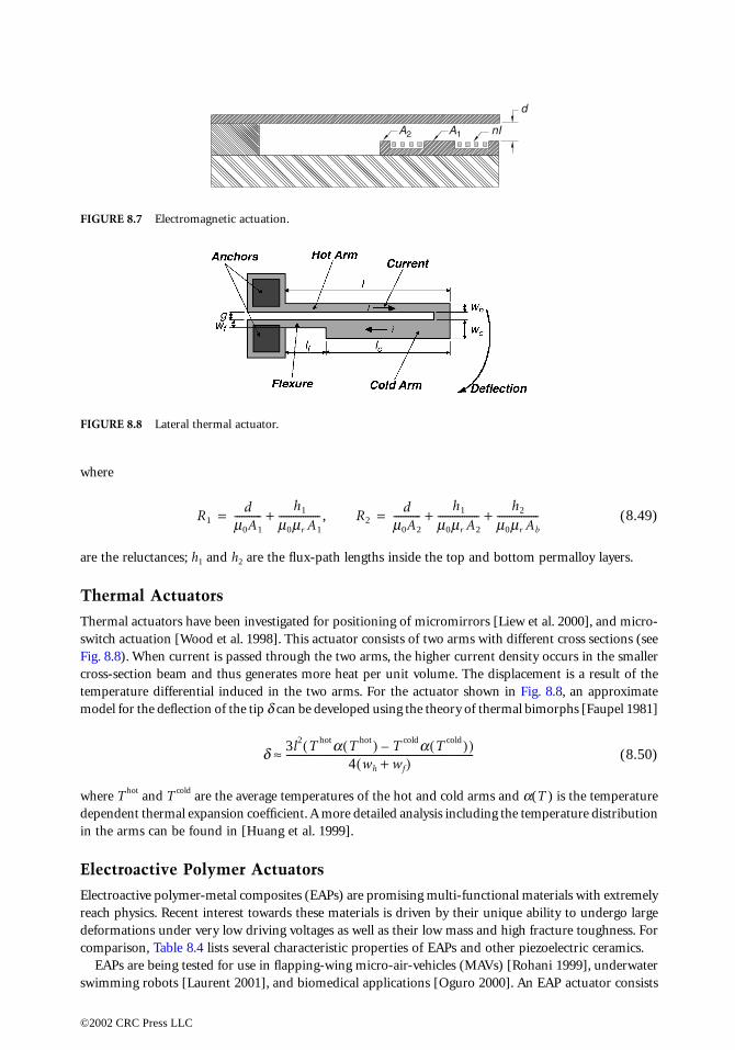
Thermal actswitch actuaFig. 8.8). Whcross-sectiontemperaturemodel for th
where T hot adependent tin the arms
Electroac
Electroactivereach physicdeformationcomparison
EAPs are swimming r
FIGURE 8.7
FIGURE 8.8
A2 A1 nI
d
0066_Frame_C08 Page 13 Wednesday, January 9, 2002 3:48 PM
©2002 CRC P
(8.49)
tances; h1 and h2 are the flux-path lengths inside the top and bottom permalloy layers.
Actuators
uators have been investigated for positioning of micromirrors [Liew et al. 2000], and micro-tion [Wood et al. 1998]. This actuator consists of two arms with different cross sections (seeen current is passed through the two arms, the higher current density occurs in the smaller beam and thus generates more heat per unit volume. The displacement is a result of the
differential induced in the two arms. For the actuator shown in Fig. 8.8, an approximatee deflection of the tip δ can be developed using the theory of thermal bimorphs [Faupel 1981]
(8.50)
nd T cold are the average temperatures of the hot and cold arms and α(T ) is the temperaturehermal expansion coefficient. A more detailed analysis including the temperature distributioncan be found in [Huang et al. 1999].
tive Polymer Actuators
polymer-metal composites (EAPs) are promising multi-functional materials with extremelys. Recent interest towards these materials is driven by their unique ability to undergo larges under very low driving voltages as well as their low mass and high fracture toughness. For
, Table 8.4 lists several characteristic properties of EAPs and other piezoelectric ceramics.being tested for use in flapping-wing micro-air-vehicles (MAVs) [Rohani 1999], underwaterobots [Laurent 2001], and biomedical applications [Oguro 2000]. An EAP actuator consists
Electromagnetic actuation.
Lateral thermal actuator.
R1d
m0A1
-----------h1
m0mr A1
----------------- , R2+ dm0A2
-----------h1
m0mr A2
-----------------h2
m0mr Ab
-----------------+ += =
d 3l2 T hota T hot( ) T colda T cold( )–( )4 wh wf+( )
-----------------------------------------------------------------------------≈
ress LLC
of an ion-excation of a pin Fig. 8.9(bPont, USA )actuator app
where M+ isaccording towith diamet1982] accordof these chan
Metal-polsurface of this based on exchange of in the membmicrophotog0.8 µm thicelectrodes in
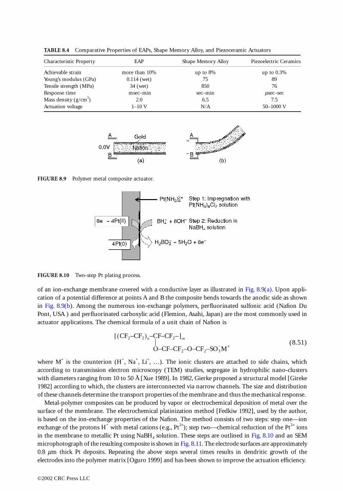
TABLE 8.4 Comparative Properties of EAPs, Shape Memory Alloy, and Piezoceramic Actuators
Characteristic Property EAP Shape Memory Alloy Piezoelectric Ceramics
Achievable Young’s moTensile streResponse tiMass densitActuation v
FIGURE 8.9
FIGURE 8.10
0066_Frame_C08 Page 14 Wednesday, January 9, 2002 3:48 PM
©2002 CRC P
change membrane covered with a conductive layer as illustrated in Fig. 8.9(a). Upon appli-otential difference at points A and B the composite bends towards the anodic side as shown). Among the numerous ion-exchange polymers, perfluorinated sulfonic acid (Nafion Du and perfluorinated carboxylic acid (Flemion, Asahi, Japan) are the most commonly used inlications. The chemical formula of a unit chain of Nafion is
(8.51)
the counterion (H+, Na+, Li+, …). The ionic clusters are attached to side chains, which transmission electron microscopy (TEM) studies, segregate in hydrophilic nano-clusters
ers ranging from 10 to 50 Å [Xue 1989]. In 1982, Gierke proposed a structural model [Girekeing to which, the clusters are interconnected via narrow channels. The size and distributionnels determine the transport properties of the membrane and thus the mechanical response.
ymer composites can be produced by vapor or electrochemical deposition of metal over thee membrane. The electrochemical platinization method [Fedkiw 1992], used by the author,
the ion-exchange properties of the Nafion. The method consists of two steps: step one—ionthe protons H+ with metal cations (e.g., Pt2+); step two—chemical reduction of the Pt2+ ionsrane to metallic Pt using NaBH4 solution. These steps are outlined in Fig. 8.10 and an SEMraph of the resulting composite is shown in Fig. 8.11. The electrode surfaces are approximately
k Pt deposits. Repeating the above steps several times results in dendritic growth of theto the polymer matrix [Oguro 1999] and has been shown to improve the actuation efficiency.
strain more than 10% up to 8% up to 0.3%dulus (GPa) 0.114 (wet) 75 89ngth (MPa) 34 (wet) 850 76me msec–min sec–min µsec–secy (g/cm3) 2.0 6.5 7.5oltage 1–10 V N/A 50–1000 V
Polymer metal composite actuator.
Two-step Pt plating process.
CF2–CF2( )n–CF–CF2–[ ]m
O–CF–CF2–O–CF2–SO3−M+
ress LLC

The deforinant one beerling 1998]in Fig. 8.12.generated tofree water monium ions.the polymerstrain (eigenelastic deforstrain propo
FIGURE 8.11
FIGURE 8.12
0066_Frame_C08 Page 15 Wednesday, January 9, 2002 3:48 PM
©2002 CRC P
mation of the polymer-metal composite can be attributed to several phenomena, the dom-ing differential swelling of the membrane due to internal osmotic pressure gradients [Eik-
. A schematic representation of the ionic processes taking place inside the polymer is shown Under the application of external electric field a flux of cations and hydroxonium ions iswards the cathode. At the cathode the ions pick up an electron and produce hydrogen andolecules. On the anodic side, the water molecules dissociate producing oxygen and hydrox- This redistribution of water within the membrane creates local expansion/contraction of matrix. Mathematically, the deformation can be described by introducing an additional strain) term in the expression of the total strain. Thus the total strain has two additive parts:mation of the polymer network due to external forces (mechanical, electrical) and chemicalrtional to the compositional variables
(8.52)
Nafion membrane with Pt electrode.
Ion transort in nafion.
Anode Cathode
+ _
4H
3O+ +
4e−
→ 4
H2O
(liq.
) +
2H
2(ga
s)
Li+
+ O
H−
→ L
iOH
6H
2O(li
q.)
→ 4
H3O
+ +
4e−
+ O
2(ga
s)
e− S
urfa
ce E
lect
ric C
urre
nt (
elec
tron
s)
e− S
urfa
ce E
lect
ric C
urre
nt (
elec
tron
s)
H2O+ Li+ H+
H2O
D'Arcy Flow (osmotic pressure gradient)
Electroosmotic Drag
eij eijelast r0
Vs
3Ms--------- cs c0
s–( )dij
s
∑+=
ress LLC
where cs are the mass fractions, are the partial molar volumes, Ms are the molar masses, and the index0 refers to the initial value of a variable. Complete mathematical description of the polymer actuatorrequires thefor potentiaconsequenceterm in thecomponent in a relaxati
where W s isactivity coefappear in a fthe referenc
8.6 Fu
The future Mfor exampleIC componeMEMS usinearlier, the sstructures. FFor examplincreased admechatronic
Reference
Butt, H., Jaspp. 1–
Eikerling, MosmoElectro
Evans, T.H.,Enikov, E.T.
force Enikov, E.T.
actuat2000.
Falvo, M.R.,contac
Faupel, J.H.,Ed., W
Liu, R., Her,nizati
Gierke, T.D.braneChem
Vs
0066_Frame_C08 Page 16 Wednesday, January 9, 2002 3:48 PM
©2002 CRC P
solution of mass transport (diffusion) equation, momentum balance, and Poisson equationl distribution, the discussion of which is beyond the scope of this book. An interesting of the addition of the chemical strain in (8.46) is the explicit appearance of the pressure
electrochemical potential driving the diffusion. The total mass diffusion flux will have aproportional to the negative gradient of the pressure, which for the case of water, will resulton phenomena observed experimentally. The total flux of component s is then given by
(8.53)
the mobility of component s, zs is the valence of component s, p is the pressure, f s is theficient, and Φ is the electric potential. We have omitted the cross-coupling terms that wouldully coupled Onsager-type formulation. Interested readers are referred to [Enikov 2000b] andes therein for further details.
ture Trends
EMS are likely to be more heterogeneous in terms of materials and structures. Bio-MEMS, require use of nontoxic, noncorrosive materials, which is not a severe concern in standardnts. Already departure from the traditional Si-based MEMS can be seen in the areas of opticalg wide band-gap materials, nonlinear electro-optical polymers, and ceramics. As pointedubmicron size of the cantilever-based sensors brings the thermal noise issues in mechanicalurther reduction in size will require molecular statistic description of the interaction forces.e, carbon nanotubes placed on highly oriented pyrolytic graphite (HOPG) experiencehesion force when aligned with the underlying graphite lattice [Falvo et al. 2000]. The future systems are likely to become an interface between the macro and nano domains.
s
chke, M., “Calculation of thermal noise in atomic force microscopy,” Nanotechnology, 6,7, 1995.., Kharkats, Y.I., Kornyshev, A.A., Volfkovich, Y.M., “Phenomenological theory of electro-
tic effect and water management in polymer proton-conducting membranes,” Journal of thechemical Society, 145(8), pp. 2684–2698, 1998.
Journal of Applied Mechanics, 6, p. A-7, 1939., Nelson, B., “Three dimensional microfabrication for multi-degree of freedom capacitivesensor using fiber chip coupling,” J. Micromech. Microeng., 10, pp. 492–497, 2000., Nelson, B.J., “Electrotransport and deformation model of ion exhcange membrane basedors,” in Smart Structures and Materials 2000, Newport Beach, CA, SPIE vol. 3987, March,
Steele, J., Taylor, R.M., Superfine, R., “Gearlike rolling motion mediated by commensuratet: carbon nanotubes on HOPG,” Physical Review B, 62(6), pp. 665–667, 2000.
Fisher, F.E., Engineering Design: A Synthesis of Stress Analysis and Materials Engineering, 2ndiley & Sons, New York, 1981.
W.H., Fedkiw, P.S., “In situ electrode formation on a nafion membrane by chemical plati-on,” Journal of the Electrochemical Society, 139(1), pp. 15–23, 1990., Hsu, W.S., “The cluster-network model of ion clusturing in perfluorosulfonated mem-s,” in Perfluorinated Ionomer Membranes, A. Eisenberg and H.L. Yeager, Eds., vol. 180, Americanical Society, 1982.
Js rcsWs
Ms--------------∇ mos T( ) pV
sRT fcs( ) zsΦ+ln+ +( )–=
ress LLC

Johnson et al., “Electrophysics of micromechanical comb actuators,” Journal of MicroelectromechanicalSystems, 4(1), pp. 49–59, 1995.
Hopkins, DeHuang, Q.A
mechaKittel, Ch., ILaurent, G.,
tors,” Liew, L. et a
tronicMaugin, G., Mendelson, Nye, J.F., PhOnishi, K.,
actuatPeterson, “DRohani, M.R
AircraTimoshenkoWood, R. etXue, T., Tre
microZgonik et al
Physic
0066_Frame_C08 Page 17 Wednesday, January 9, 2002 3:48 PM
©2002 CRC P
sign Analysis of Shafts and Beams, 2nd Ed., Malabar, FL: RE Kreiger, 1987.., Lee, N.K.S., “Analysis and design of polysilcon thermal flexture actuator,” Journal of Micro-nics and Microengineering, 9, pp. 64–70, 1999.ntroduction to Solid State Physics, John Wiley & Sons, Inc., New York, 1996.Piat, E., “High efficiency swimming microrobot using ionic polymer metal composite actua-to appear in 2001.l., “Modeling of thermal actuator in a bulk micromachined CMOS micromirror,” Microelec-s Journal, 31(9–10), pp. 791–790, 2000.Continuum Mechanics of Electromagnetic Solids, Elsevier, Amsterdam, The Netherlands, 1988.Plasticity: Theory and Application, Macmillan, New York, 1968.ysical Properties of Crystals, Oxford University Press, London, 1960.Sewa, Sh., Asaka, K., Fujiwara, N., Oguro, K., “Bending response of polymer electrolyteor,” in Smart Structures and Materials 2000, Newport Beach, CA, SPIE vol. 3987, March, 2000.ynamic micromechanics on silicon: techniques and devices,” IEEE, 1978.., Hicks, G.R., “Multidisciplinary design and prototype of a micro air vehicle,” Journal of
ft, 36(1), p. 237, 1999., S., Woinowsky-Krieger, S., Theory of Plates and Shells, McGraw-Hill, New York, 1959.
al., “MEMS microrelays,” Mechatronics, 8, pp. 535–547, 1998.nt, Y.S., Osseo-Asare, K., “Characterization of nafion membranes by transmision electronscopy,” Journal of Membrane Science, 45, p. 261, 1989.., ‘‘Dielectric, elastic, piezoelectric, electro-optic and elasto-optic tensors of BaTiO3 crystals,”al Review B, 50(9), p. 5841, 1994.
ress LLC