Embed Size (px)
Citation preview
Prepared by Prof.V.K.Jain 1
Chapter 8
Digital Transmission
Prepared by Prof.V.K.Jain 2
Lecture Outcome
On completing of this lecture, you should be able to:Compare analog and digital communication techniquesCalculate the information capacity of a channelDescribe the common types of analog pulse modulationDescribe PCM and dynamic rangeDescribe signal companding

Prepared by Prof.V.K.Jain 3
Introduction
Digital communication is the transmittal of digital pulses between two or more points.Original source can be in digital or in analog forms.Analog signal needs to be digitized prior to transmission.Digital communication also need a channel for transmission as required by the analog communication.
Prepared by Prof.V.K.Jain 4
Advantages of Digital Transmission
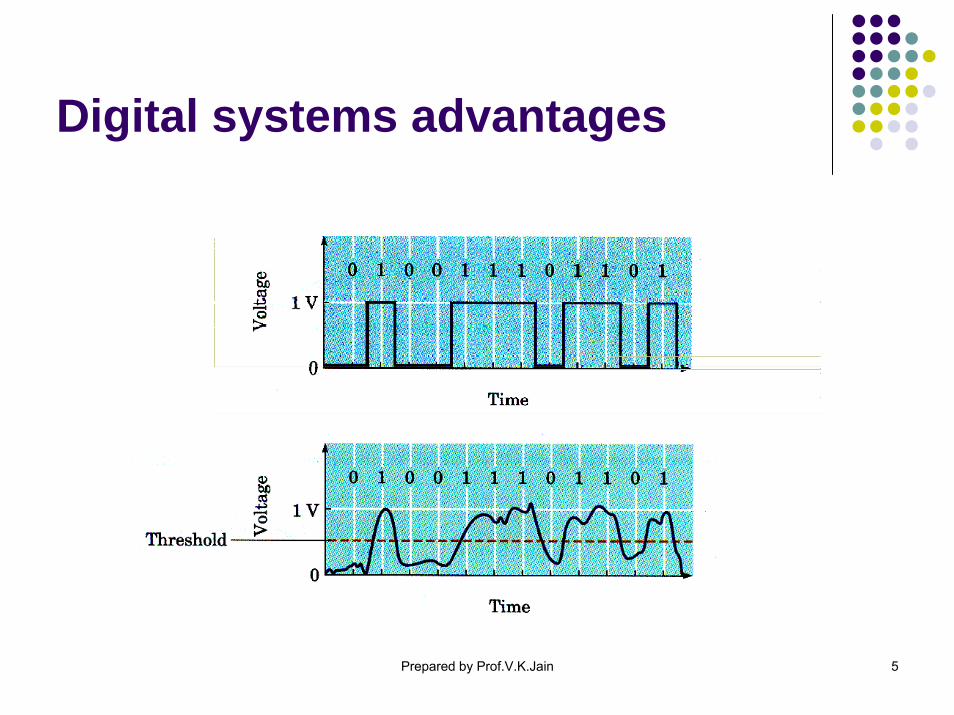
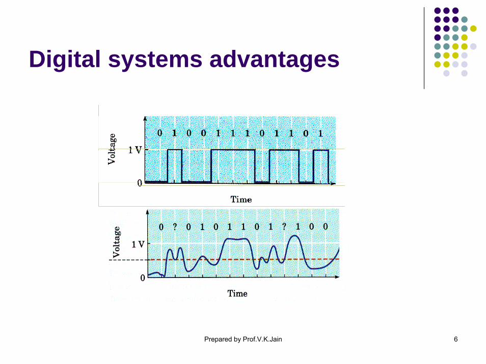
Better immunity against noise than analog.Better suited than analog for processing, storage, and combination using multiplexing. Simpler to measure and evaluate than analog.Transmission errors can be detected and corrected more easily and correctly than is possible with analog.
Prepared by Prof.V.K.Jain 5
Digital systems advantages
Prepared by Prof.V.K.Jain 6
Digital systems advantages
Prepared by Prof.V.K.Jain 7
Disadvantages of Digital Transmission
Transmission of digitally encoded analog signals requires significantly more bandwidth than analog transmission.Analog signal must be first converted to digital pulses prior to transmission and converted back to analog at receiver.Digital transmission requires precise time synchronization between the clocks in transmitter and receiver.
Prepared by Prof.V.K.Jain 8
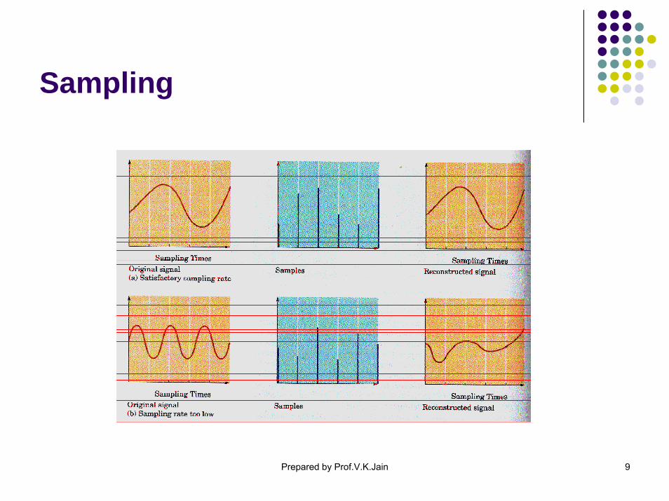
Sampling
To transmit analog signal by digital means, it is first necessary to sample it.In 1928, Harry Nyquist proved, signal can be reconstructed from periodic samples as long as sampling rate is at least twice the highest frequency of the signal.
In telephony, sampling frequency is 8 kHz for maximum audio frequency of 3.4 kHz.In CD system, sampling frequency is 44.1 kHz for maximum audio frequency of 20 kHz.
Prepared by Prof.V.K.Jain 9
Sampling
Prepared by Prof.V.K.Jain 10
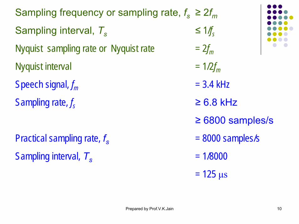
Sampling frequency or sampling rate, fs ≥ 2fmSampling interval, Ts ≤ 1/fsNyquist sampling rate or Nyquist rate = 2fmNyquist interval = 1/2fmSpeech signal, fm = 3.4 kHz
Sampling rate, fs ≥ 6.8 kHz
≥ 6800 samples/s
Practical sampling rate, fs = 8000 samples/s
Sampling interval, Ts = 1/8000
= 125 μs
Prepared by Prof.V.K.Jain 11
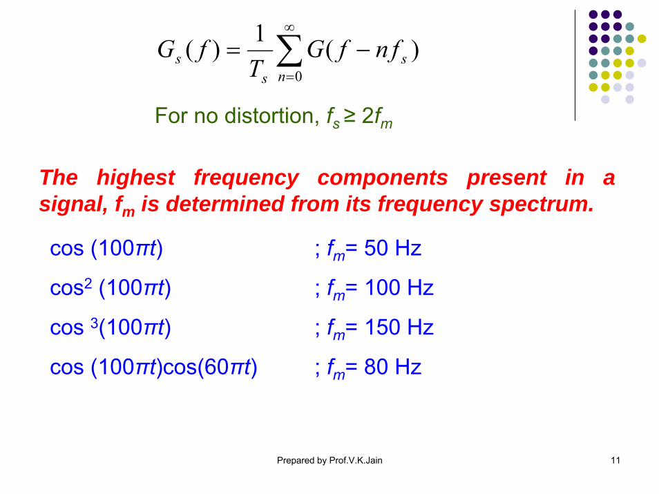
The highest frequency components present in a signal, fm is determined from its frequency spectrum.
cos (100πt) ; fm= 50 Hz
cos2 (100πt) ; fm= 100 Hz
cos 3(100πt) ; fm= 150 Hz
cos (100πt)cos(60πt) ; fm= 80 Hz
For no distortion, fs ≥ 2fm
)(1)(0
sns
s fnfGT
fG ∑∞
=
−=

Prepared by Prof.V.K.Jain 12
Time Division Multiplexing (TDM)US T1 1.544 Mb/s 24 Voice Signals
T2 6.312 96T3 44.736 672T4 274.176 4032
Europe E1 2.048 30E2 8.448 120E3 34.368 480E4 139.264 1920E5 564.992 7680

Prepared by Prof.V.K.Jain 13
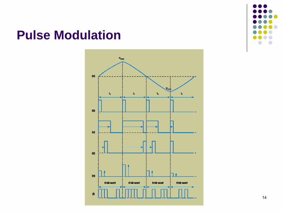
Pulse modulation
Pulse modulation consists of sampling, converting samples to pulses, and transmission over a physical medium.Four major pulse modulation techniques
Pulse Width Modulation (PWM)Pulse Position Modulation (PPM)Pulse Amplitude Modulation (PAM)Pulse Code Modulation (PCM)
Prepared by Prof.V.K.Jain 14
Pulse Modulation
Prepared by Prof.V.K.Jain 15
Pulse Code Modulation (PCM)
In PCM, the available range of signal is divided into N levels and each assigned a binary number.Each sample is represented by the closest level to its amplitude.In linear PCM, levels are separated by equal voltage gradations.In nonlinear PCM, levels are separated by unequal voltage gradations.Number of levels depends on number of bits to express each sample (level). 2nN =
Prepared by Prof.V.K.Jain 16
Quantization and Binary Coding
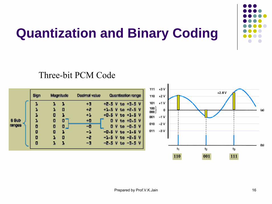
Three-bit PCM Code
110 001 111110 001 111
Prepared by Prof.V.K.Jain 17
Quantization and Binary Coding
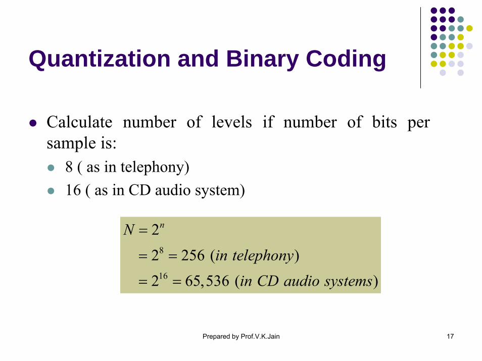
Calculate number of levels if number of bits per sample is:
8 ( as in telephony)16 ( as in CD audio system)
8
16
22 256 ( )2 65,536 ( )
nNin telephony
in CD audio systems
=
= =
= =
Prepared by Prof.V.K.Jain 18
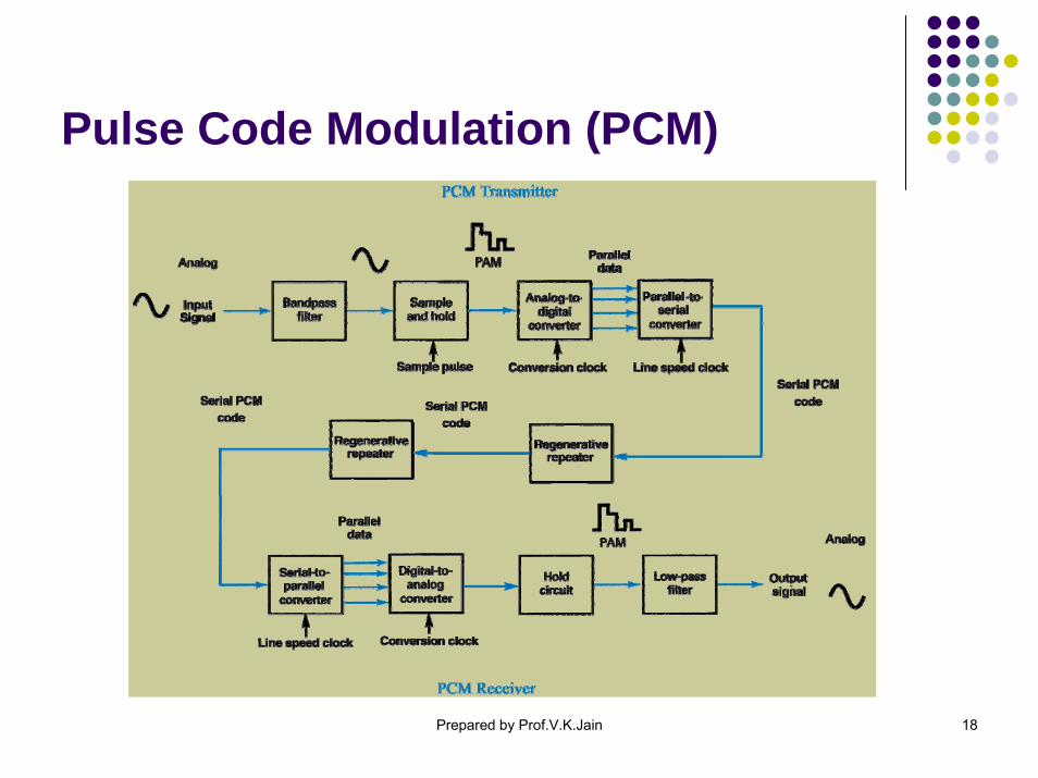
Pulse Code Modulation (PCM)
Prepared by Prof.V.K.Jain 19
Quantization and Binary Coding
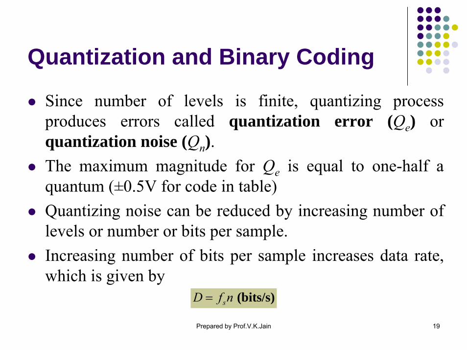
Since number of levels is finite, quantizing process produces errors called quantization error (Qe) or quantization noise (Qn).The maximum magnitude for Qe is equal to one-half a quantum (±0.5V for code in table)Quantizing noise can be reduced by increasing number of levels or number or bits per sample.Increasing number of bits per sample increases data rate, which is given by
(bits/s)sD f n=

Prepared by Prof.V.K.Jain 20
Quantization and Binary CodingDynamic Range (DR)
Quantum is the difference between adjacent levels.Magnitude of quantum is called resolution.
Resolution of PCM code shown in table is 1 V.
Dynamic range (DR) is the ratio of largest possible magnitude to the smallest possible magnitude (other than zero) that can be decoded by D/A at receiver.
max max
min
( ) 20log( )
V VDRV resolution
DR dB DR
= =
=
Prepared by Prof.V.K.Jain 21
Quantization and Binary CodingDynamic Range (DR)
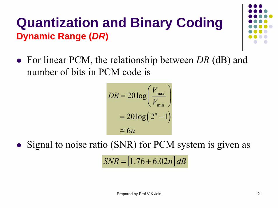
For linear PCM, the relationship between DR (dB) and number of bits in PCM code is
Signal to noise ratio (SNR) for PCM system is given as
( )
max
min
20 log
20log 2 1
6
n
VDRV
n
⎛ ⎞= ⎜ ⎟
⎝ ⎠
= −
≅
[ ]dBnSNR 02.676.1 +=

Prepared by Prof.V.K.Jain 22
Quantization and Binary CodingDynamic Range (DR)
Find the maximum dynamic range and SNR of a linear PCM using 16-bits quantizing.
Calculate the data rate needed to transmit audio with sampling rate 40 kHz and 14 bits per sample.
66 16 96
DR n dBdB
≅≅ × =
3 340 10 14 560 10 560 / sD f n
kb s
= ×
= × × = × =
( )( )1.76 6.02
1.76 96.32 98.08
SNR n dB
dB dB
= +
= + =
Prepared by Prof.V.K.Jain 23
Signal-to-Quantization Noise Ratio (SQR)
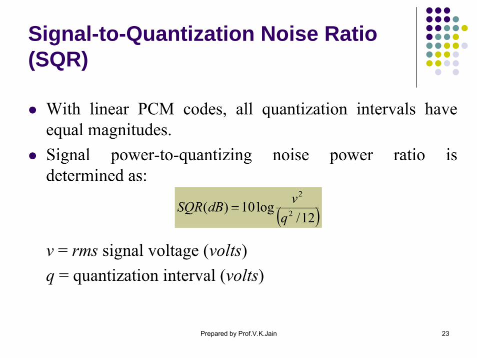
With linear PCM codes, all quantization intervals have equal magnitudes.Signal power-to-quantizing noise power ratio is determined as:
v = rms signal voltage (volts)q = quantization interval (volts)
( )12/log10)( 2
2
qvdBSQR =
Prepared by Prof.V.K.Jain 24
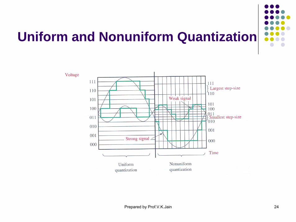
Uniform and Nonuniform Quantization
Prepared by Prof.V.K.Jain 25
Companding
Companding is the process of compression at transmitter and then expanding at receiver.With companded systems, higher amplitude signals are compressed prior to transmission and then expanded after detection.Compressor reduces quantizing error for small signals.Different signal distributions require different companding characteristics.
Prepared by Prof.V.K.Jain 26
Companding
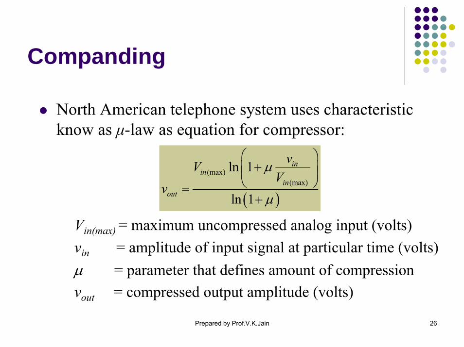
North American telephone system uses characteristic know as μ-law as equation for compressor:
Vin(max) = maximum uncompressed analog input (volts)vin = amplitude of input signal at particular time (volts)μ = parameter that defines amount of compression vout = compressed output amplitude (volts)
( )
(max)(max)
ln 1
ln 1
inin
inout
vVV
vμ
μ
⎛ ⎞+⎜ ⎟⎜ ⎟
⎝ ⎠=+
Prepared by Prof.V.K.Jain 27
Companding
Prepared by Prof.V.K.Jain 28
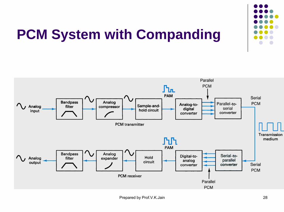
PCM System with Companding
Prepared by Prof.V.K.Jain 29
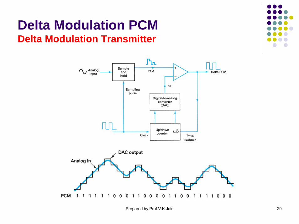
Delta Modulation PCMDelta Modulation Transmitter
Prepared by Prof.V.K.Jain 30
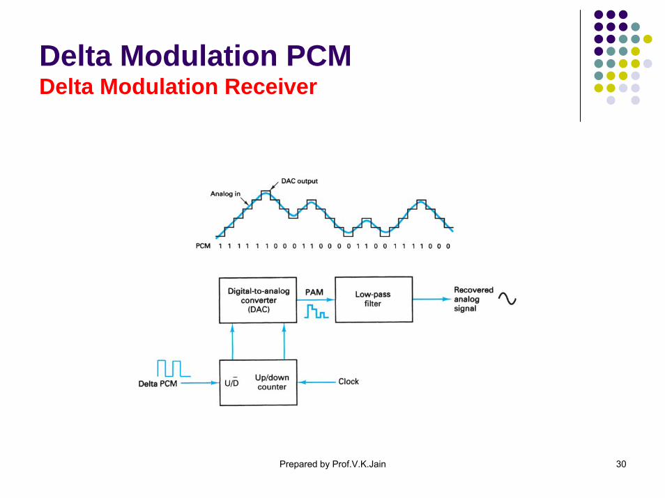
Delta Modulation PCMDelta Modulation Receiver
Prepared by Prof.V.K.Jain 31
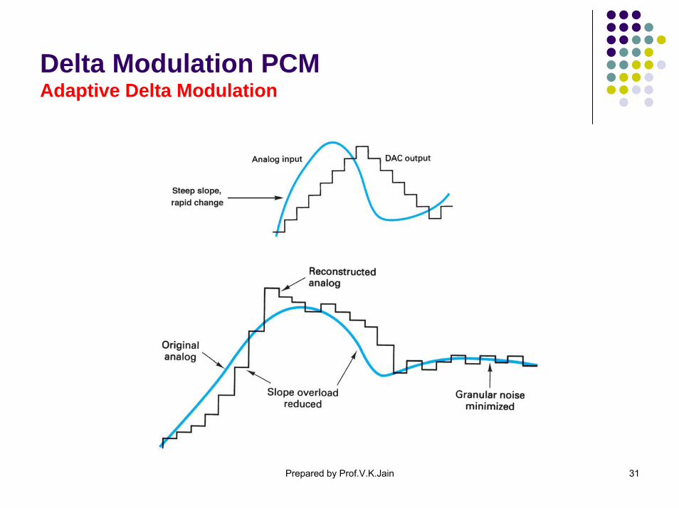
Delta Modulation PCMAdaptive Delta Modulation

Prepared by Prof.V.K.Jain 32
Points to remember
Modern communication systems are often mixture of analog and digital.Analog signal that is to be transmitted digitally must be quantized first.With PCM, more the bits used, greater is the accuracy, but higher are the bit rate and the channel bandwidth.Companding is used to increase accuracy without increasing the bit rate.
*****