Embed Size (px)
Citation preview
Chapter 8
MAT FOUNDATIONS
Omitted parts:
Sections 8.5, 8.6
Example 8.8
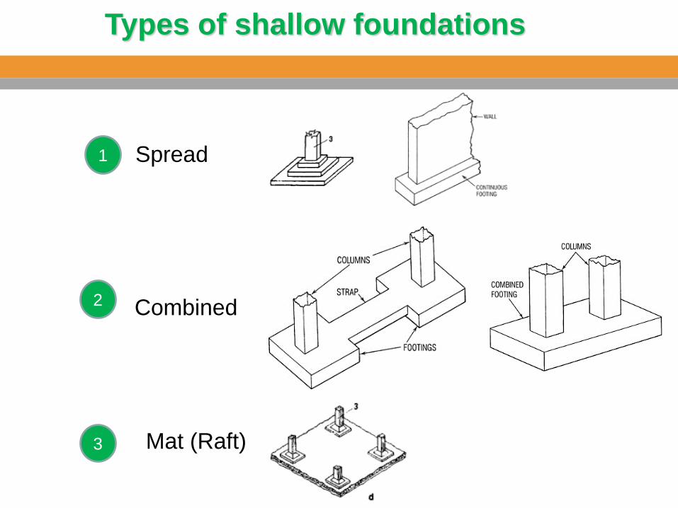
Types of shallow foundations
1
2
3
Spread
Combined
Mat (Raft)
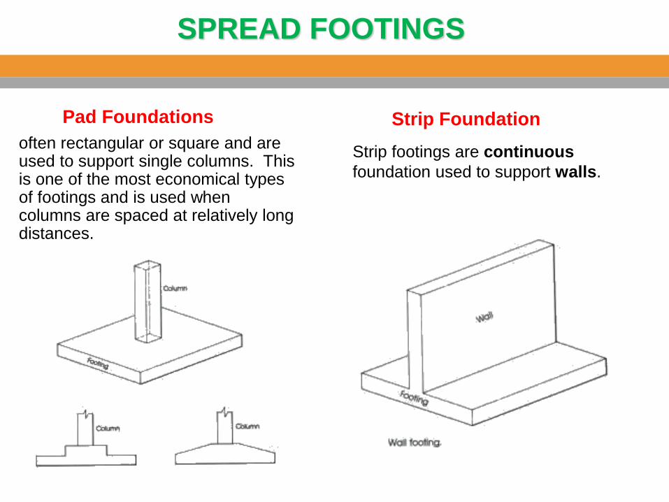
SPREAD FOOTINGS
often rectangular or square and are used to support single columns. This is one of the most economical types of footings and is used when columns are spaced at relatively long distances.
Pad Foundations
Strip footings are continuous
foundation used to support walls.
Strip Foundation
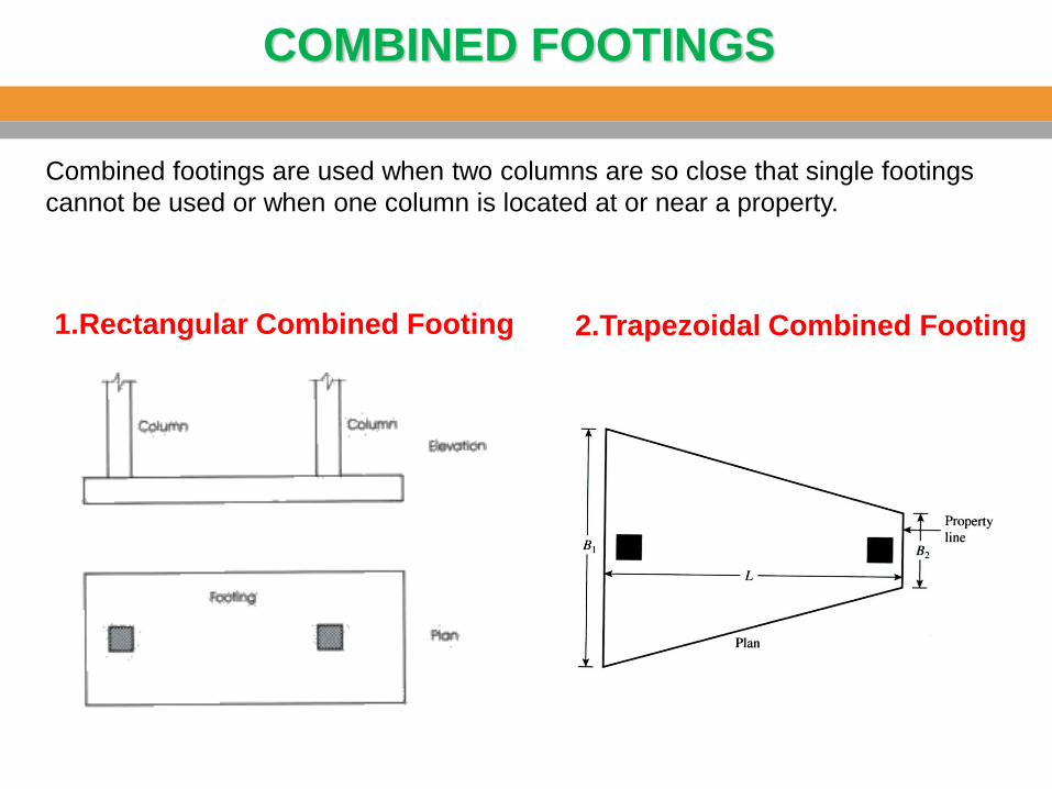
COMBINED FOOTINGS
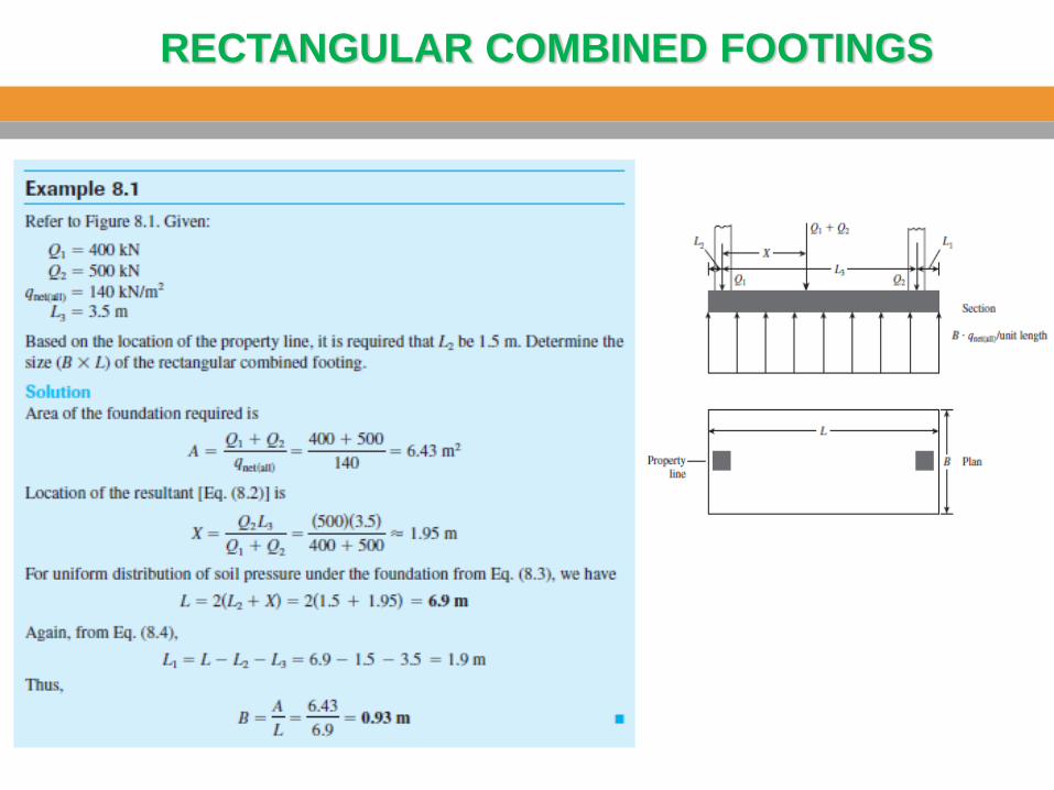
1.Rectangular Combined Footing
Combined footings are used when two columns are so close that single footings
cannot be used or when one column is located at or near a property.
2.Trapezoidal Combined Footing
COMBINED FOOTINGS
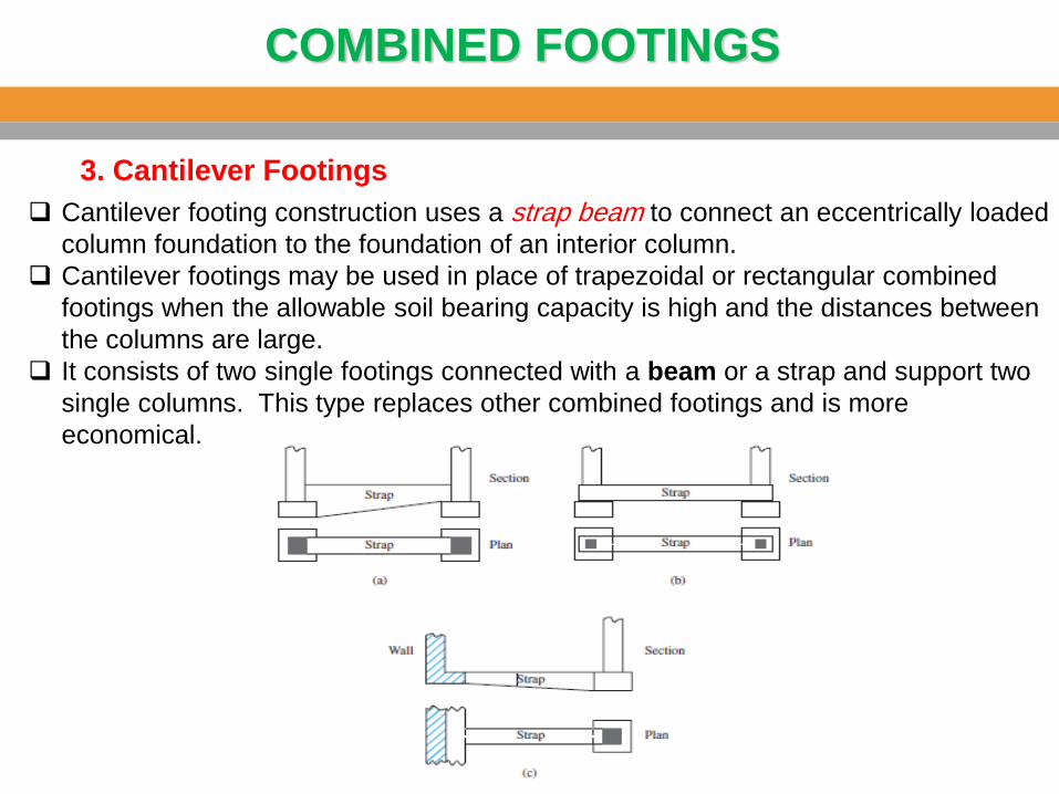
3. Cantilever Footings
Cantilever footing construction uses a strap beam to connect an eccentrically loaded
column foundation to the foundation of an interior column.
Cantilever footings may be used in place of trapezoidal or rectangular combined
footings when the allowable soil bearing capacity is high and the distances between
the columns are large.
It consists of two single footings connected with a beam or a strap and support two
single columns. This type replaces other combined footings and is more
economical.
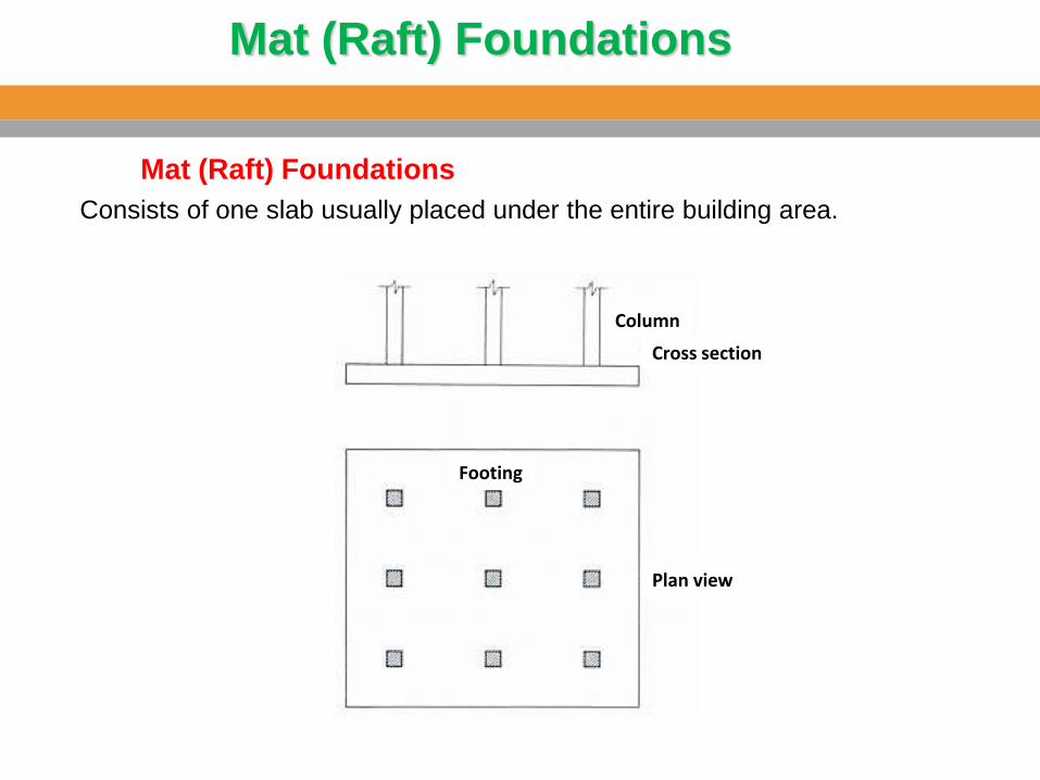
Mat (Raft) Foundations
Consists of one slab usually placed under the entire building area.
Mat (Raft) Foundations
Column
Footing
Plan view
Cross section
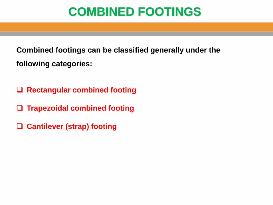
COMBINED FOOTINGS
Combined footings can be classified generally under the
following categories:
Rectangular combined footing
Trapezoidal combined footing
Cantilever (strap) footing
RECTANGULAR COMBINED FOOTINGS
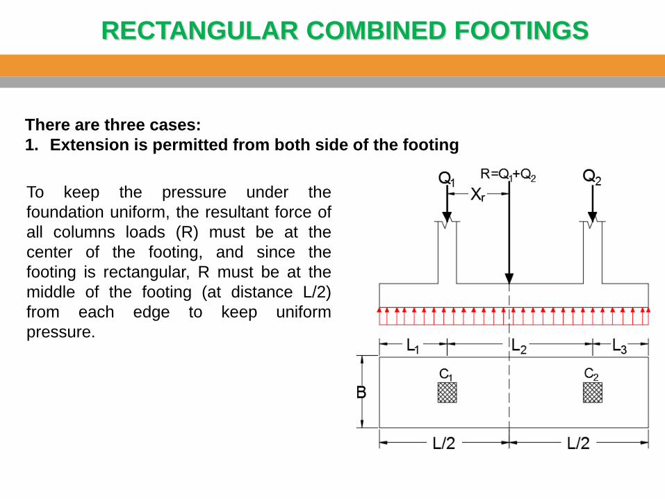
There are three cases:
1. Extension is permitted from both side of the footing
To keep the pressure under the
foundation uniform, the resultant force of
all columns loads (R) must be at the
center of the footing, and since the
footing is rectangular, R must be at the
middle of the footing (at distance L/2)
from each edge to keep uniform
pressure.
RECTANGULAR COMBINED FOOTINGS
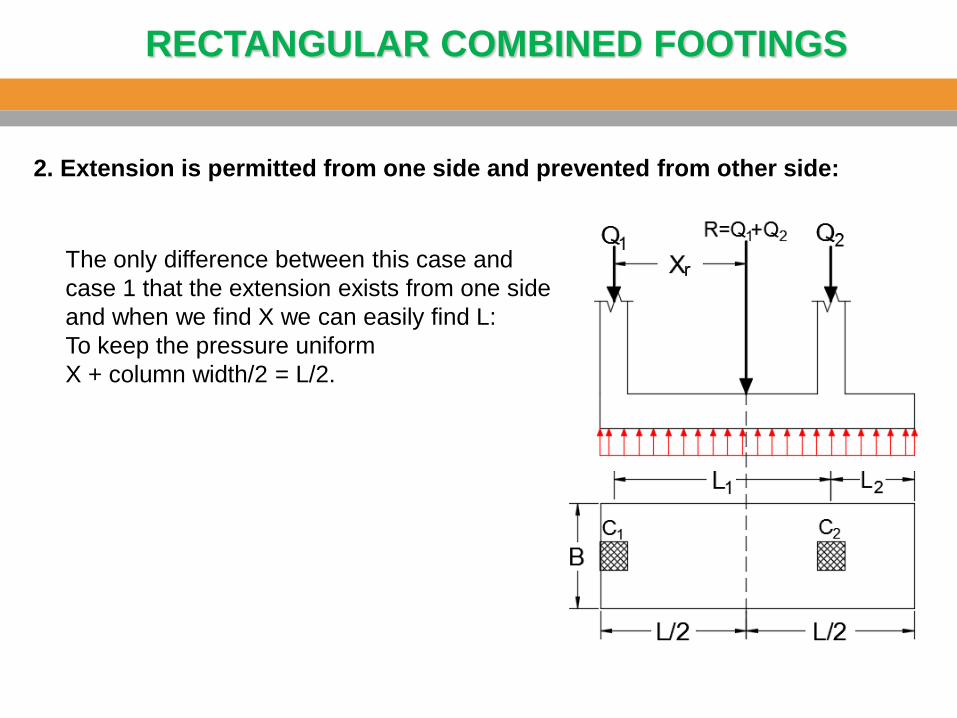
2. Extension is permitted from one side and prevented from other side:
The only difference between this case and
case 1 that the extension exists from one side
and when we find X we can easily find L:
To keep the pressure uniform
X + column width/2 = L/2.
RECTANGULAR COMBINED FOOTINGS
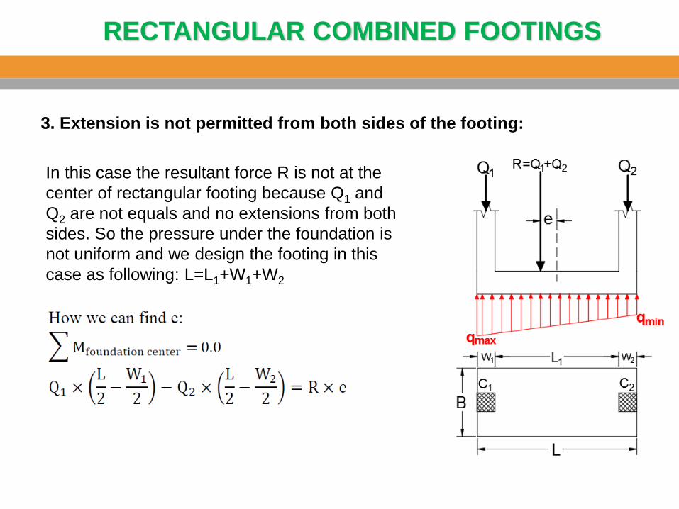
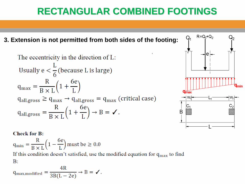
3. Extension is not permitted from both sides of the footing:
In this case the resultant force R is not at the
center of rectangular footing because Q1 and
Q2 are not equals and no extensions from both
sides. So the pressure under the foundation is
not uniform and we design the footing in this
case as following: L=L1+W1+W2
RECTANGULAR COMBINED FOOTINGS
3. Extension is not permitted from both sides of the footing:
RECTANGULAR COMBINED FOOTINGS
RECTANGULAR COMBINED FOOTINGS
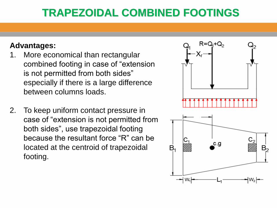
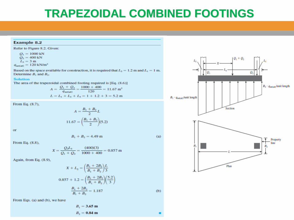
TRAPEZOIDAL COMBINED FOOTINGS
Advantages:
1. More economical than rectangular
combined footing in case of “extension
is not permitted from both sides”
especially if there is a large difference
between columns loads.
2. To keep uniform contact pressure in
case of “extension is not permitted from
both sides”, use trapezoidal footing
because the resultant force “R” can be
located at the centroid of trapezoidal
footing.
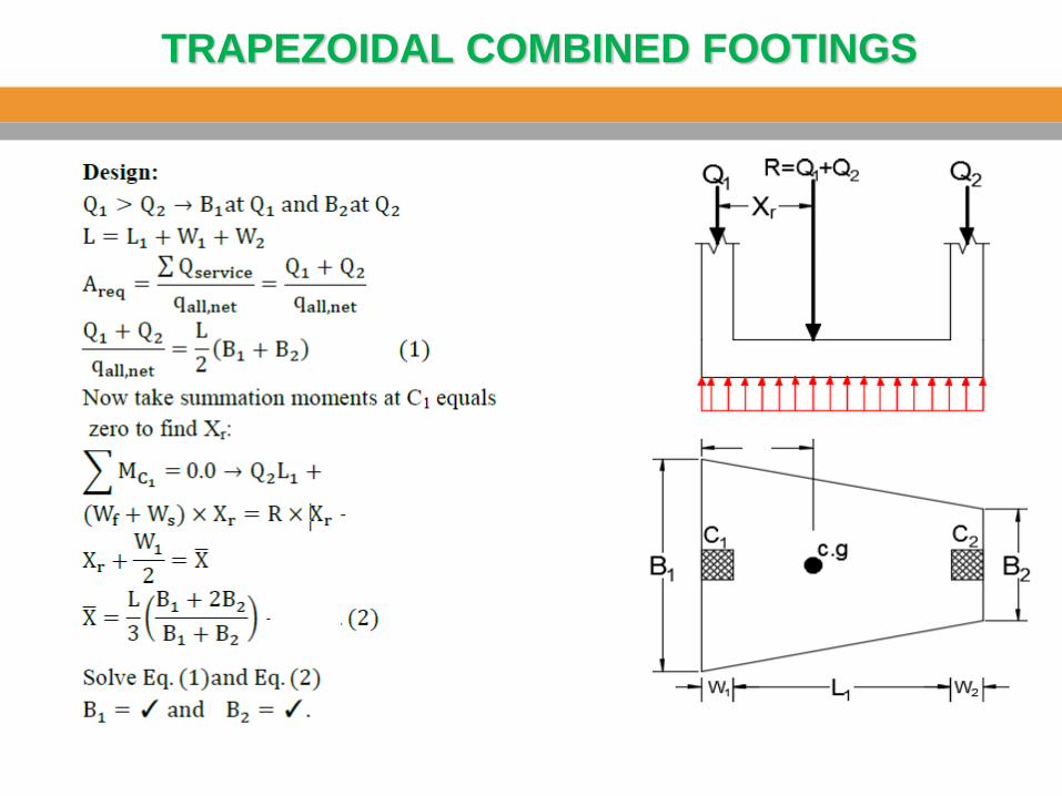
TRAPEZOIDAL COMBINED FOOTINGS
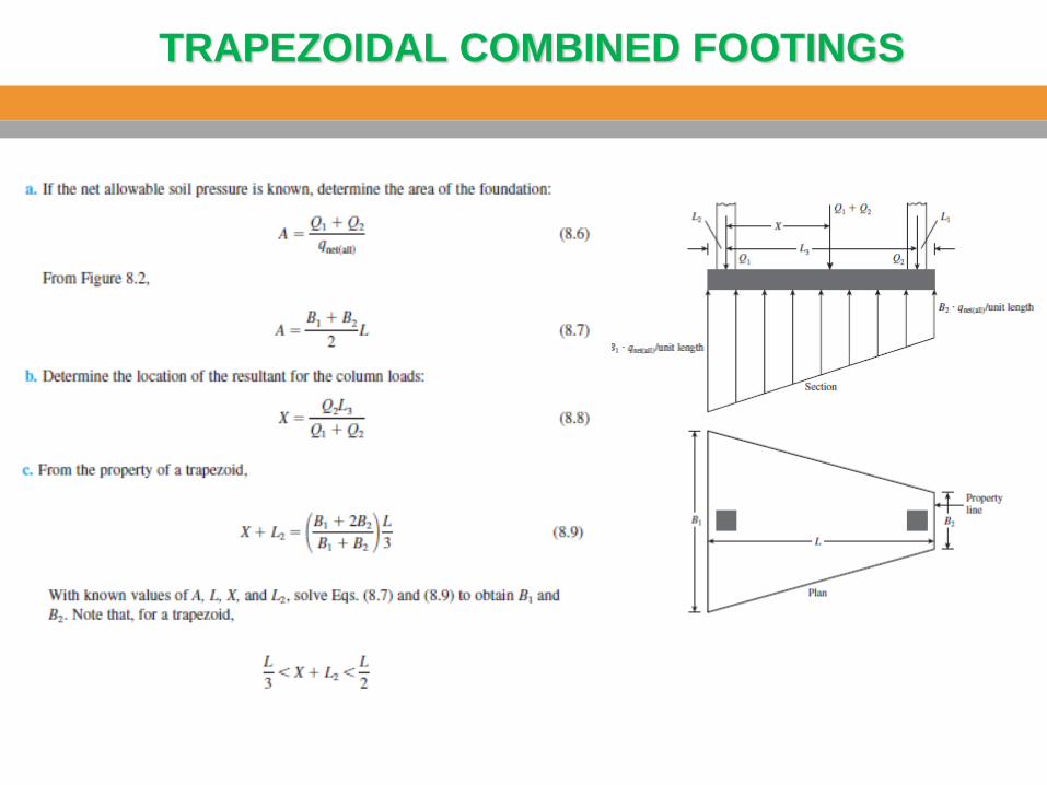
TRAPEZOIDAL COMBINED FOOTINGS
TRAPEZOIDAL COMBINED FOOTINGS
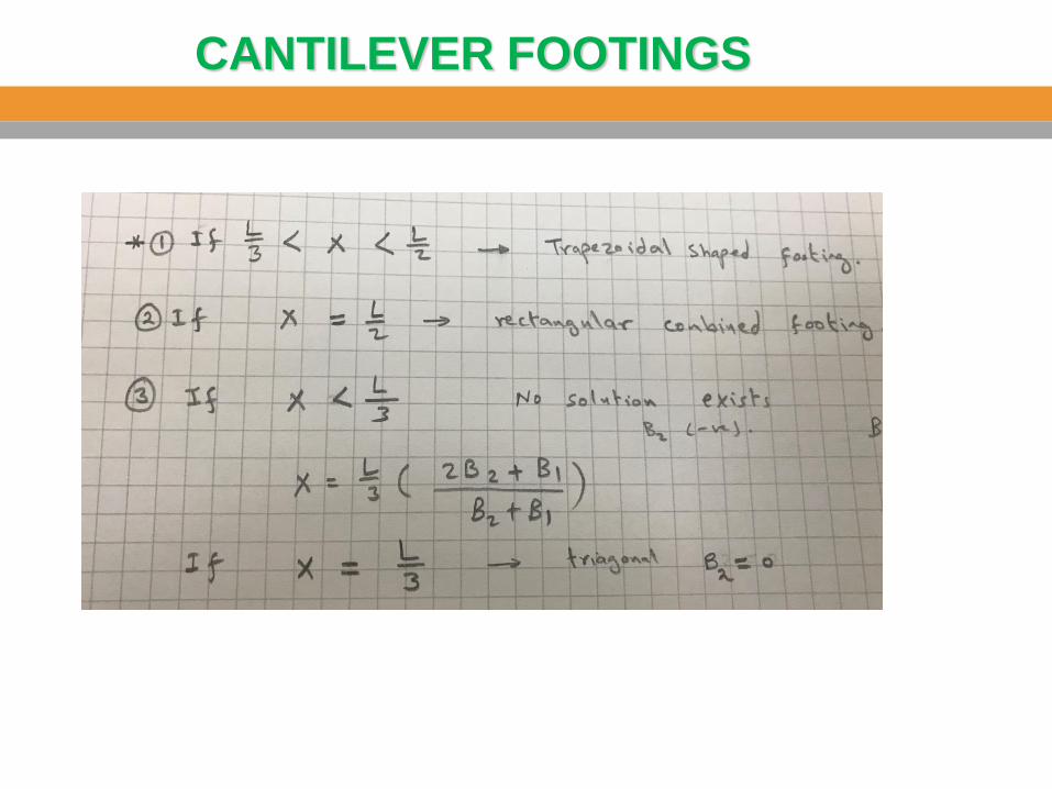
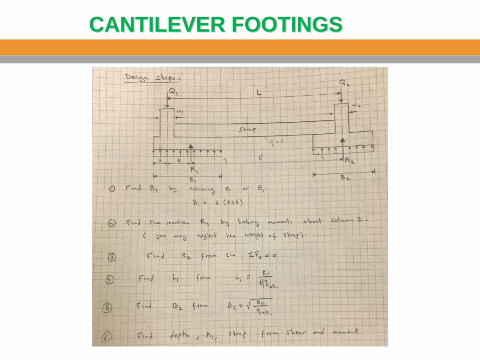
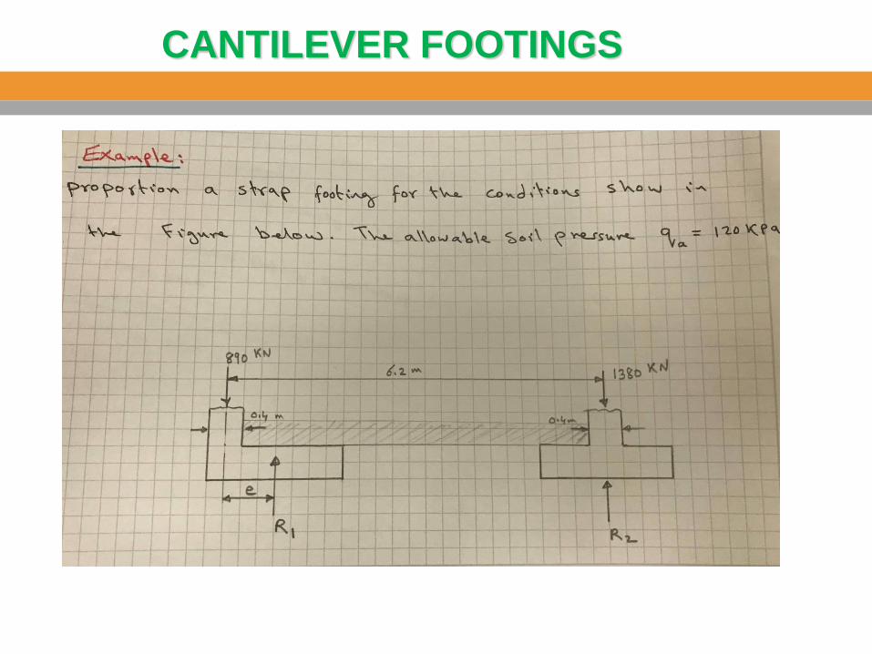
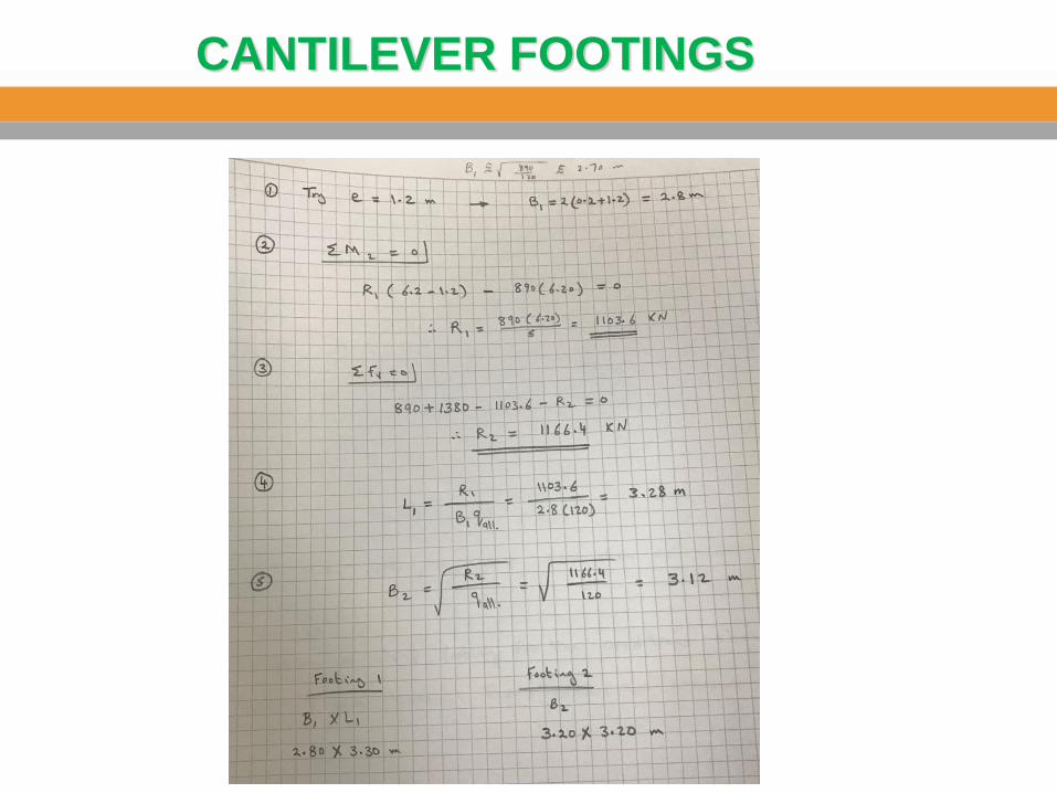
CANTILEVER FOOTINGS
1. Used when there is a property line which prevents the footing to be
extended beyond the face of the edge column. In addition to that the edge
column is relatively far from the interior column so that the rectangular and
trapezoidal combined footings will be too narrow and long which increases
the cost.
2. May be used to connect two interior foundations, one foundation has a
large load require a large area but this area not available, and the other
foundation has a small load and there is available area to enlarge this
footing, so a strap beam is used to connect these two foundations to
transfer the load from the largest to the smallest foundation.
3. There is a “strap beam” which connects two separated footings. The edge
footing is usually eccentrically loaded and the interior footing is centrically
loaded. The purpose of the beam is to prevent overturning of the
eccentrically loaded footing and to keep uniform pressure under this
foundation.
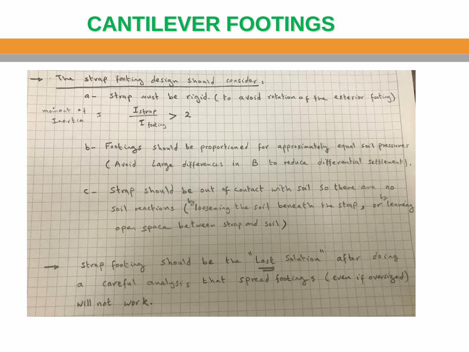
4. The strap beam doesn’t touch the ground (i.e. there is no contact between
the strap beam and the soil, so no bearing pressure applied on it).
5. This footing also called “cantilever footing” because the overall moment on
the strap beam is negative moment.
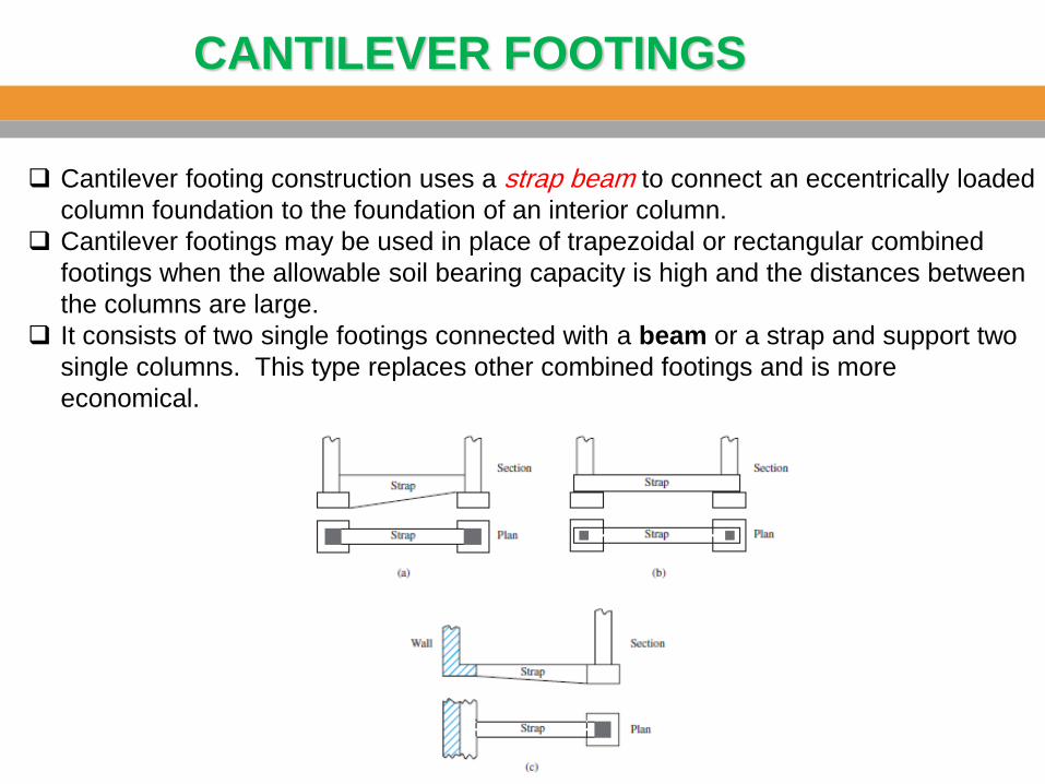
CANTILEVER FOOTINGS
Cantilever footing construction uses a strap beam to connect an eccentrically loaded
column foundation to the foundation of an interior column.
Cantilever footings may be used in place of trapezoidal or rectangular combined
footings when the allowable soil bearing capacity is high and the distances between
the columns are large.
It consists of two single footings connected with a beam or a strap and support two
single columns. This type replaces other combined footings and is more
economical.
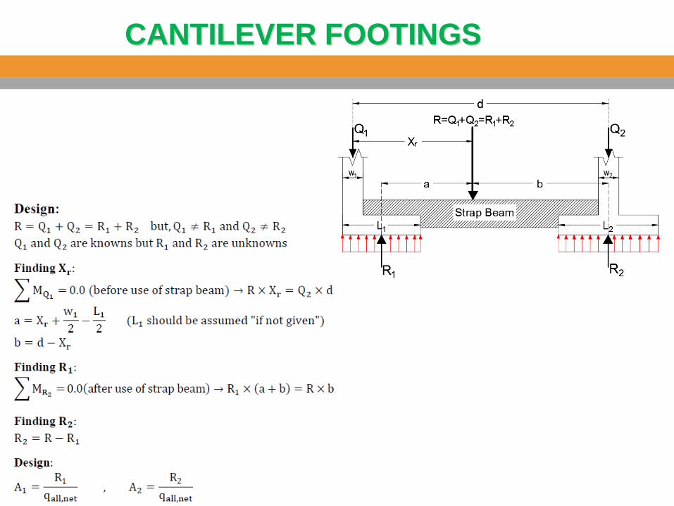
CANTILEVER FOOTINGS
CANTILEVER FOOTINGS

CANTILEVER FOOTINGS
CANTILEVER FOOTINGS
CANTILEVER FOOTINGS
CANTILEVER FOOTINGS
CANTILEVER FOOTINGS
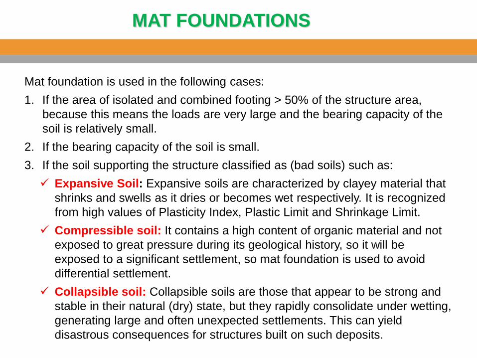
MAT FOUNDATIONS
Mat foundation is used in the following cases:
1. If the area of isolated and combined footing > 50% of the structure area,
because this means the loads are very large and the bearing capacity of the
soil is relatively small.
2. If the bearing capacity of the soil is small.
3. If the soil supporting the structure classified as (bad soils) such as:
Expansive Soil: Expansive soils are characterized by clayey material that
shrinks and swells as it dries or becomes wet respectively. It is recognized
from high values of Plasticity Index, Plastic Limit and Shrinkage Limit.
Compressible soil: It contains a high content of organic material and not
exposed to great pressure during its geological history, so it will be
exposed to a significant settlement, so mat foundation is used to avoid
differential settlement.
Collapsible soil: Collapsible soils are those that appear to be strong and
stable in their natural (dry) state, but they rapidly consolidate under wetting,
generating large and often unexpected settlements. This can yield
disastrous consequences for structures built on such deposits.
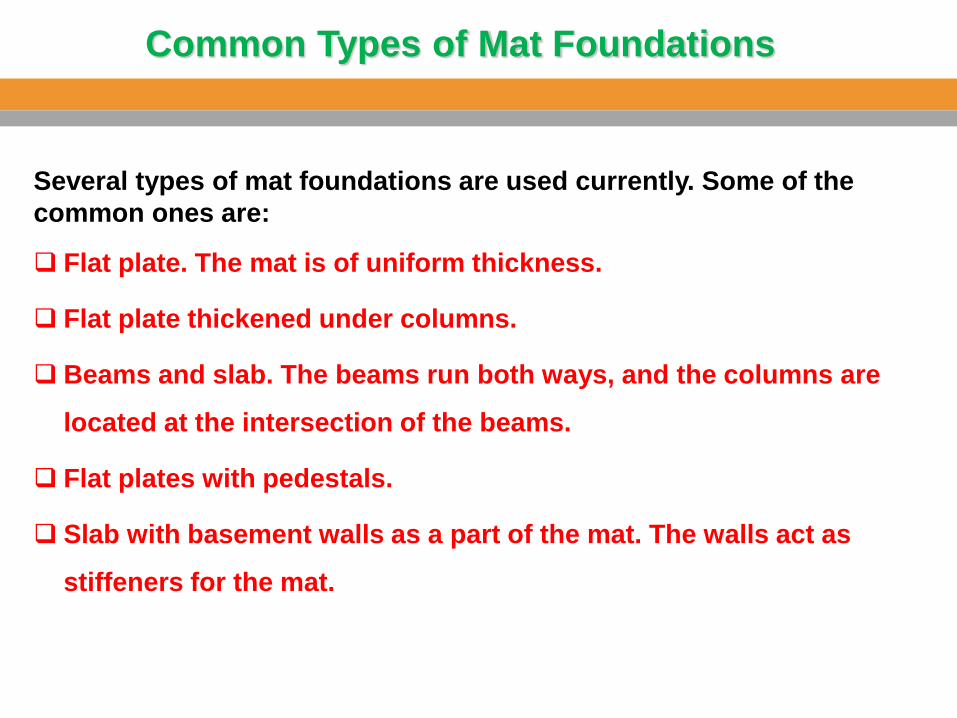
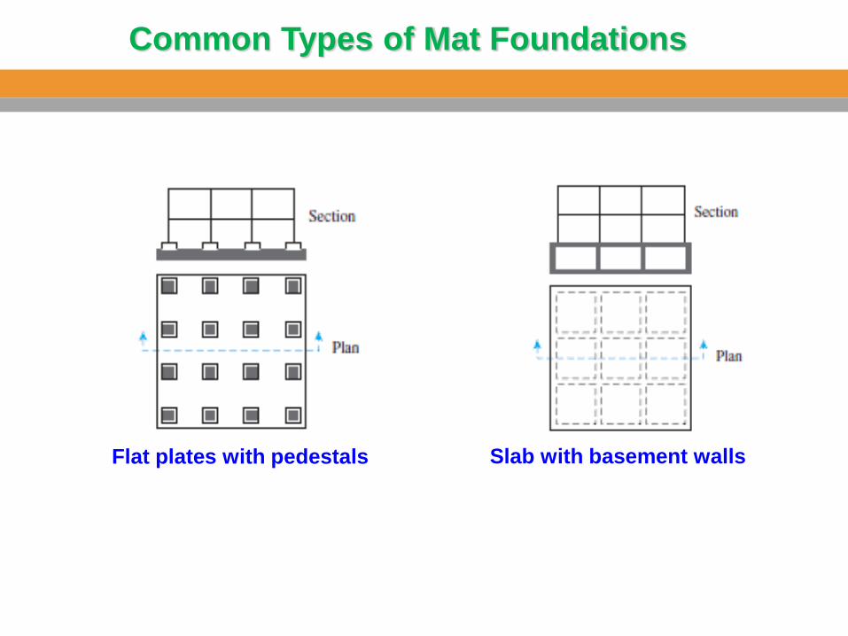
Common Types of Mat Foundations
Several types of mat foundations are used currently. Some of the
common ones are:
Flat plate. The mat is of uniform thickness.
Flat plate thickened under columns.
Beams and slab. The beams run both ways, and the columns are
located at the intersection of the beams.
Flat plates with pedestals.
Slab with basement walls as a part of the mat. The walls act as
stiffeners for the mat.
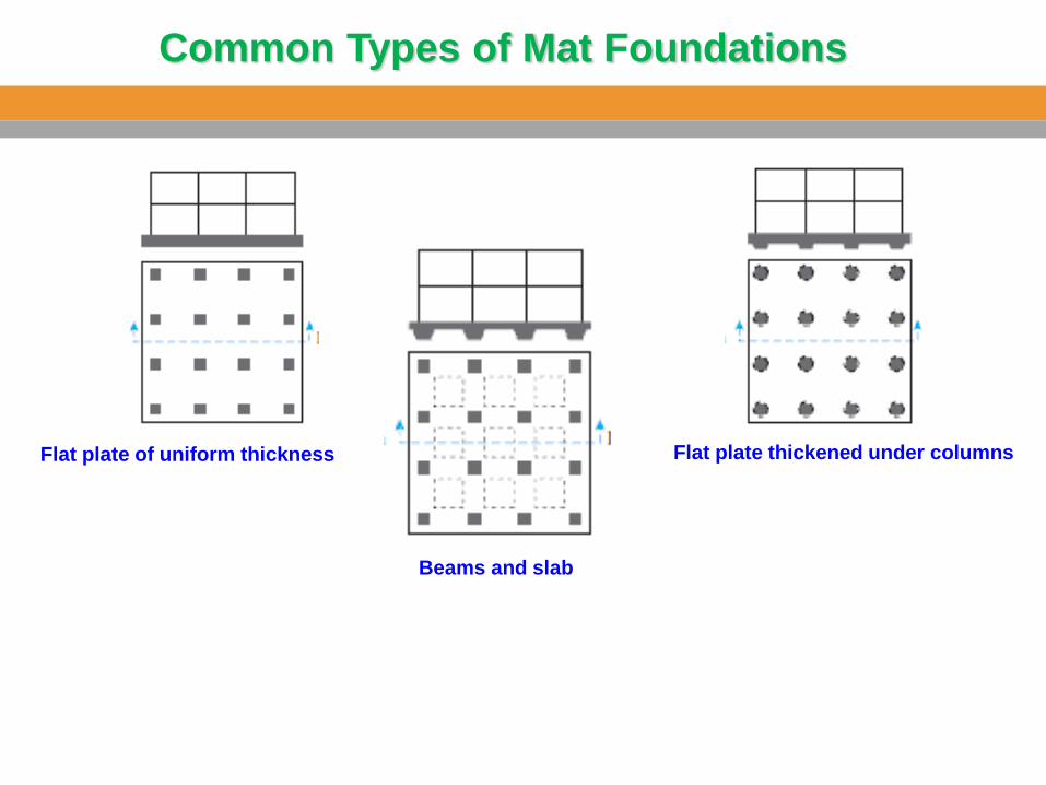
Common Types of Mat Foundations
Flat plate of uniform thickness Flat plate thickened under columns
Beams and slab
Common Types of Mat Foundations
Flat plates with pedestals Slab with basement walls
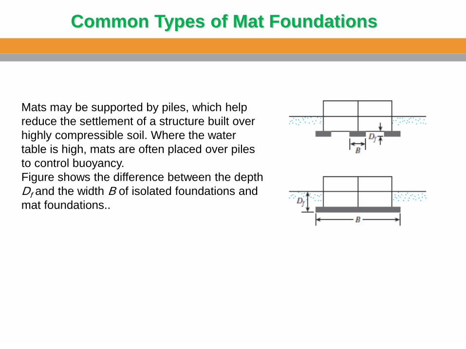
Common Types of Mat Foundations
Mats may be supported by piles, which help
reduce the settlement of a structure built over
highly compressible soil. Where the water
table is high, mats are often placed over piles
to control buoyancy.
Figure shows the difference between the depth
Df and the width B of isolated foundations and
mat foundations..
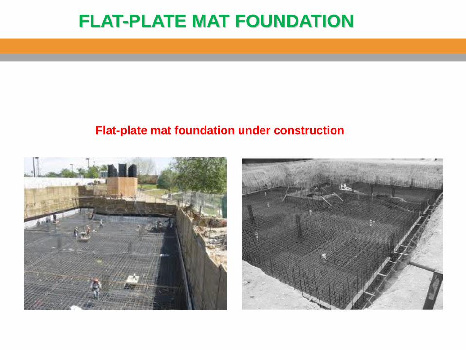
FLAT-PLATE MAT FOUNDATION
Flat-plate mat foundation under construction
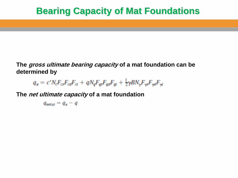
Bearing Capacity of Mat Foundations
The net ultimate capacity of a mat foundation
The gross ultimate bearing capacity of a mat foundation can be
determined by
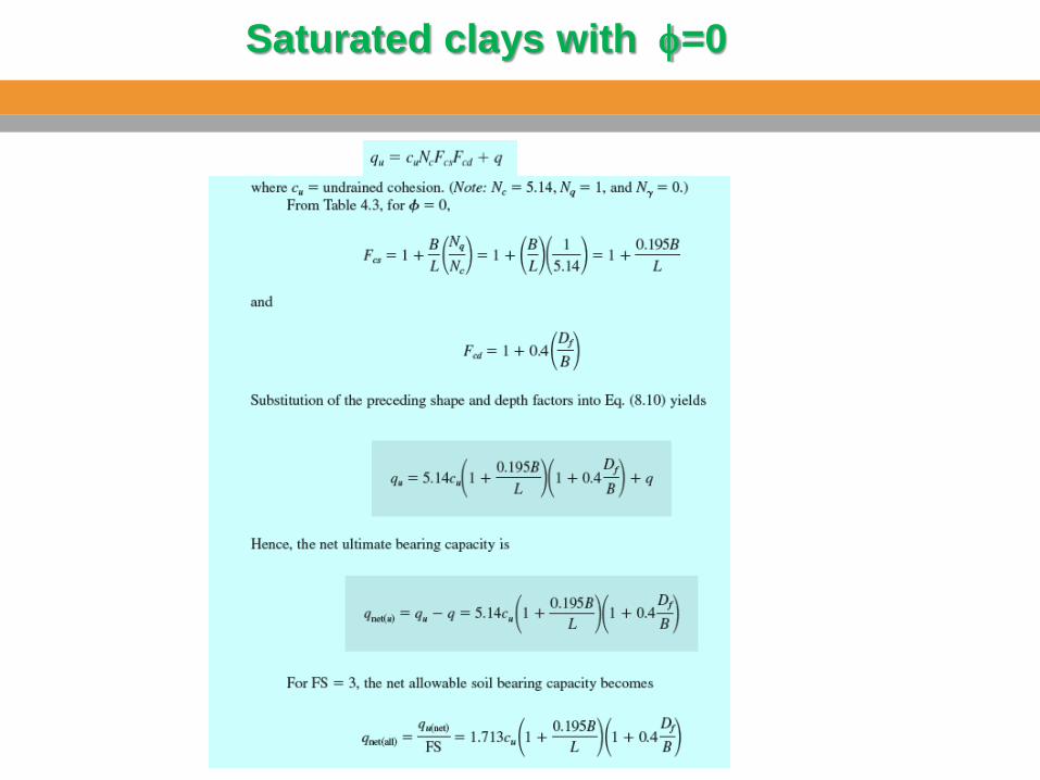
Saturated clays with f=0
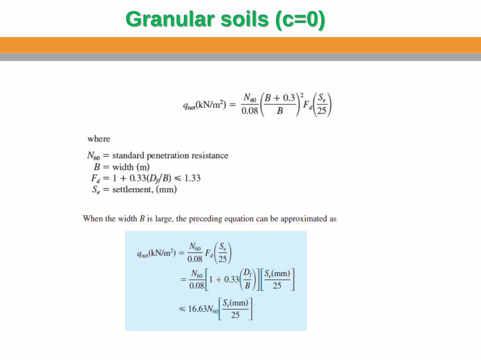
Granular soils (c=0)
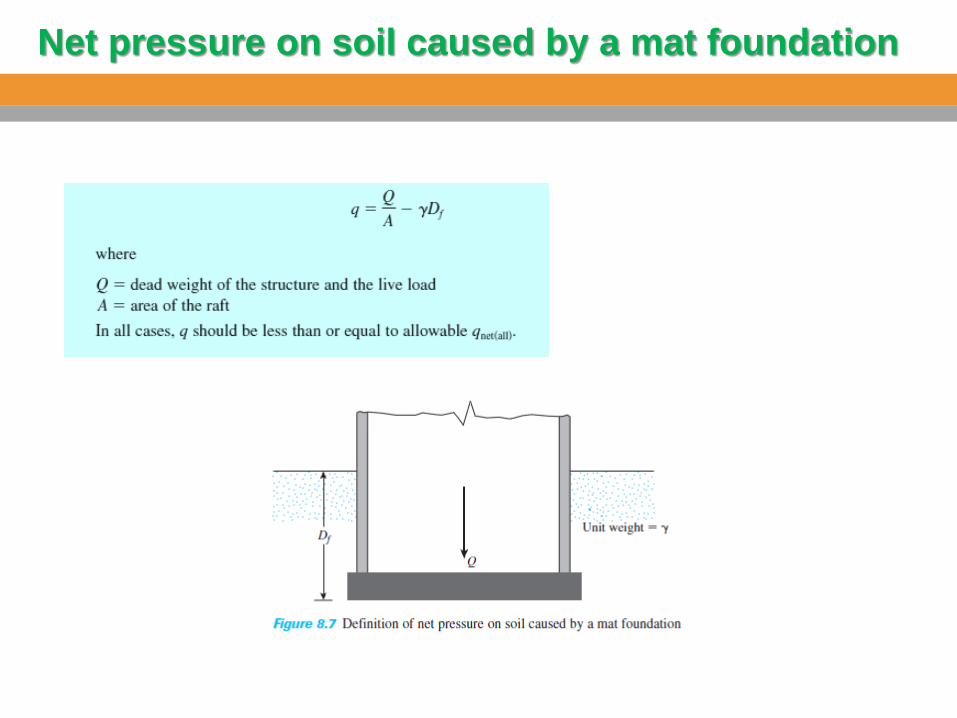
Net pressure on soil caused by a mat foundation
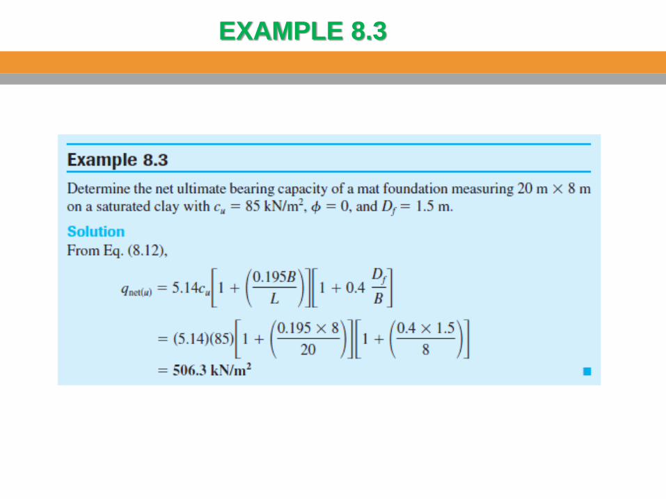
EXAMPLE 8.3
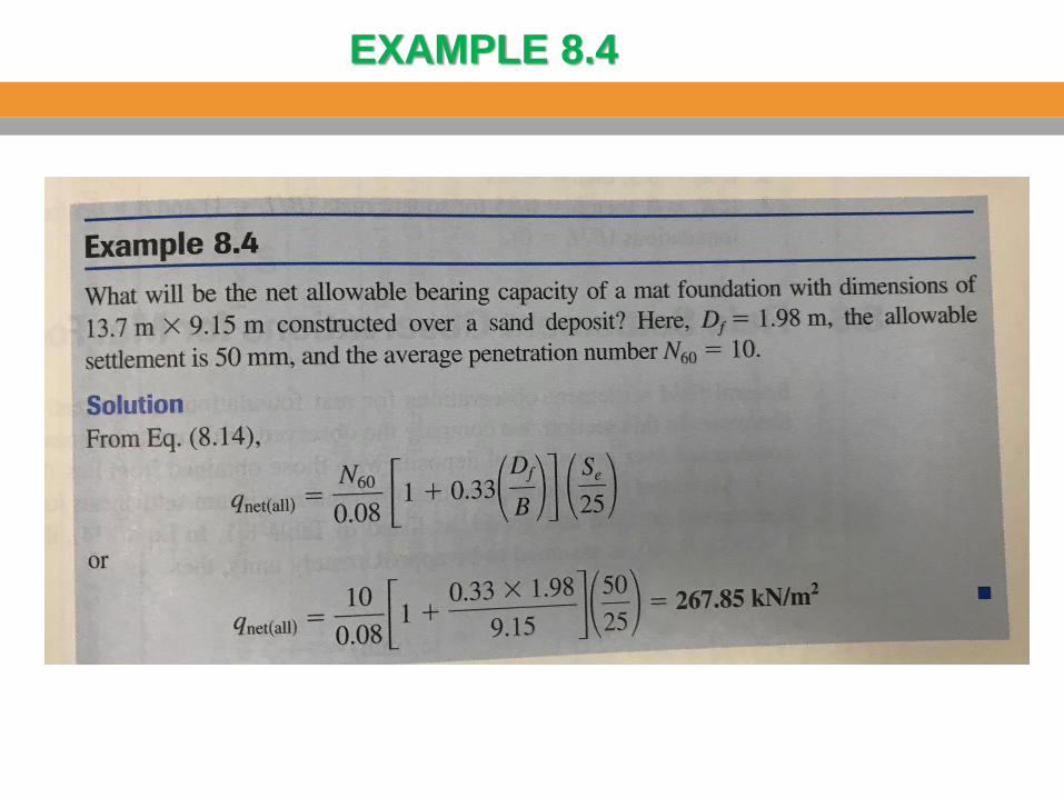
EXAMPLE 8.4
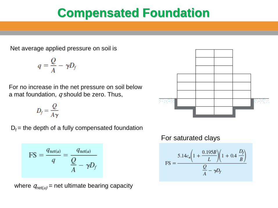
Compensated Foundation
Net average applied pressure on soil is
For no increase in the net pressure on soil below
a mat foundation, q should be zero. Thus,
Df = the depth of a fully compensated foundation
where qnet(u) = net ultimate bearing capacity
For saturated clays
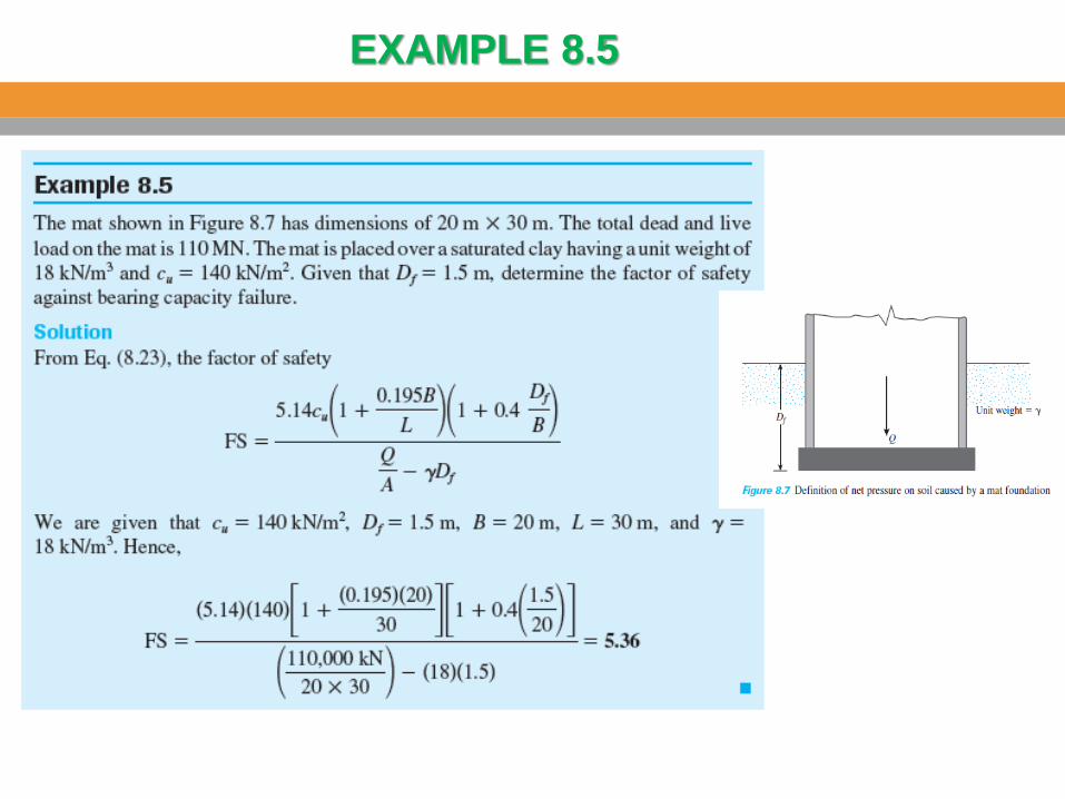
EXAMPLE 8.5
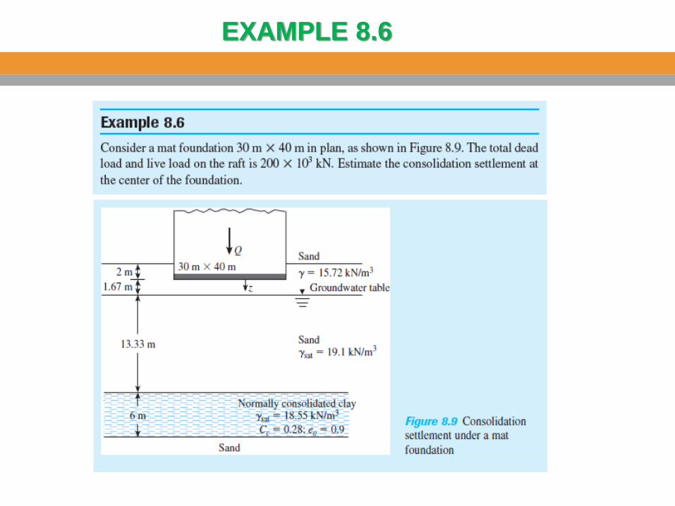
EXAMPLE 8.6
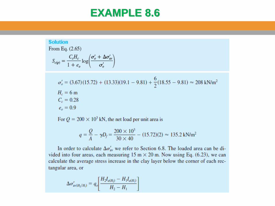
EXAMPLE 8.6
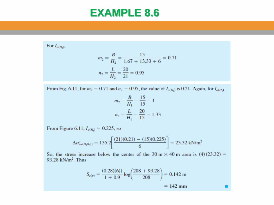
EXAMPLE 8.6
Structural Design of Mat Foundations
The structural design of mat foundations can be carried
out by the following methods:
The conventional rigid method
The approximate flexible method.
Finite-difference and finite-element methods
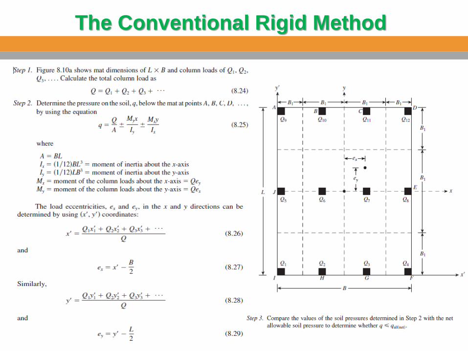
The Conventional Rigid Method
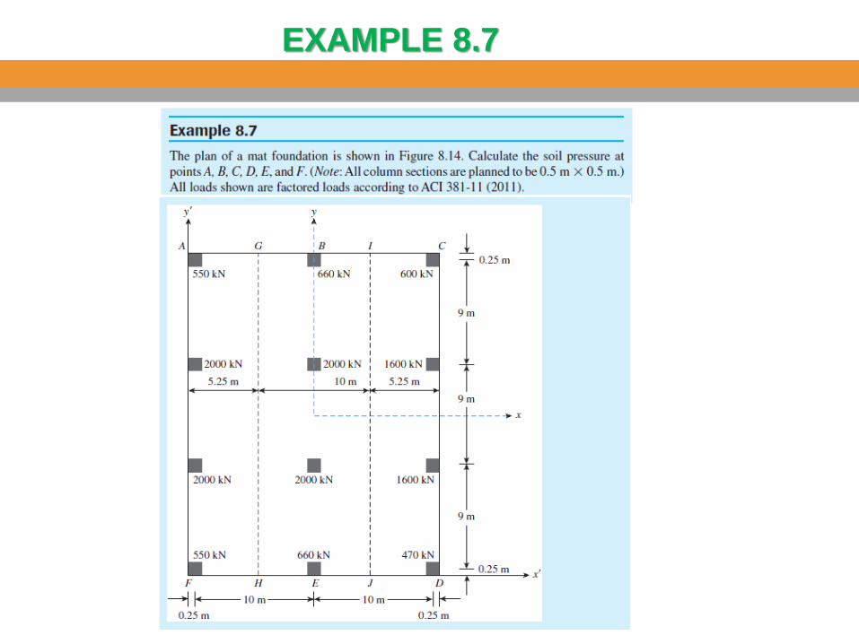
EXAMPLE 8.7
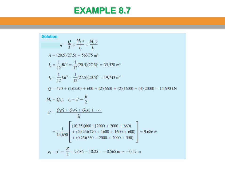
EXAMPLE 8.7
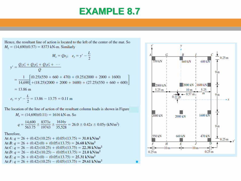
EXAMPLE 8.7

In the conventional rigid method of design, the
mat is assumed to be infinitely rigid. Also, the
soil pressure is distributed in a straight line,
and the centroid of the soil pressure is
coincident with the line of action of the
resultant column loads.
In the approximate flexible method of design,
the soil is assumed to be equivalent to an
infinite number of elastic springs, as shown in
the figure. This assumption is sometimes
referred to as the Winkler foundation. The
elastic constant of these assumed springs is
referred to as the coefficient of subgrade reaction, k.
Design of Mat Foundations
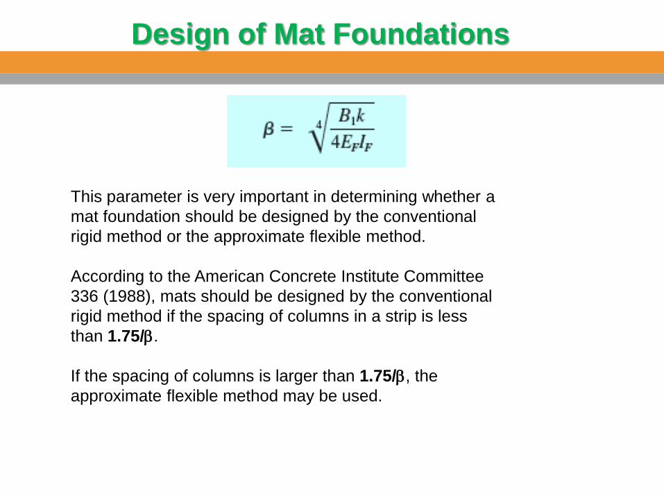
This parameter is very important in determining whether a
mat foundation should be designed by the conventional
rigid method or the approximate flexible method.
According to the American Concrete Institute Committee
336 (1988), mats should be designed by the conventional
rigid method if the spacing of columns in a strip is less
than 1.75/b.
If the spacing of columns is larger than 1.75/b, the
approximate flexible method may be used.
Design of Mat Foundations
The coefficient of subgrade reaction
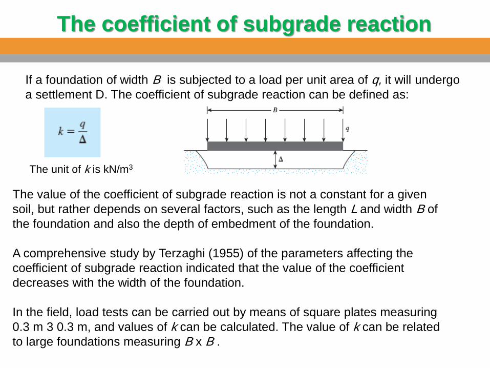
If a foundation of width B is subjected to a load per unit area of q, it will undergo
a settlement D. The coefficient of subgrade reaction can be defined as:
The unit of k is kN/m3
The value of the coefficient of subgrade reaction is not a constant for a given
soil, but rather depends on several factors, such as the length L and width B of
the foundation and also the depth of embedment of the foundation.
A comprehensive study by Terzaghi (1955) of the parameters affecting the
coefficient of subgrade reaction indicated that the value of the coefficient
decreases with the width of the foundation.
In the field, load tests can be carried out by means of square plates measuring
0.3 m 3 0.3 m, and values of k can be calculated. The value of k can be related
to large foundations measuring B x B .
The coefficient of subgrade reaction
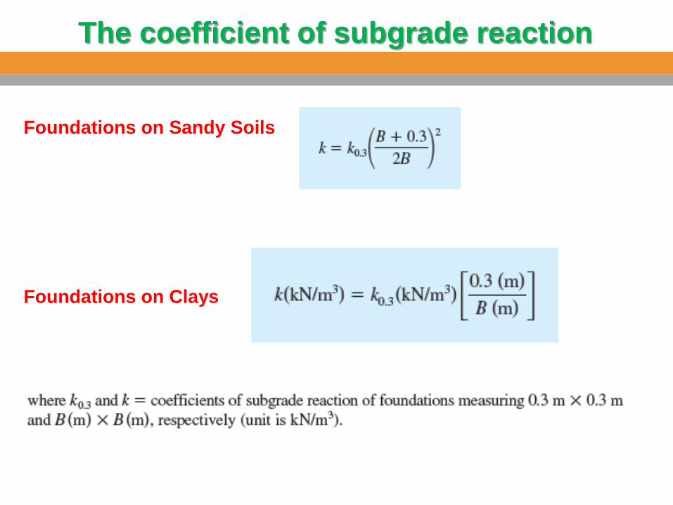
Foundations on Sandy Soils
Foundations on Clays
The coefficient of subgrade reaction
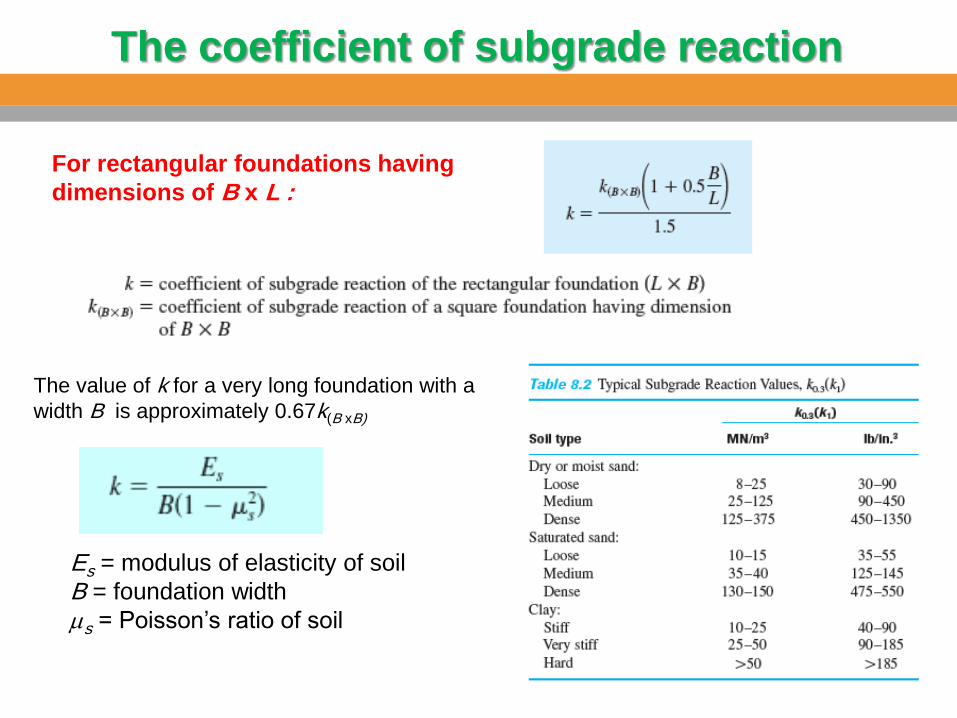
For rectangular foundations having
dimensions of B x L :
The value of k for a very long foundation with a
width B is approximately 0.67k(B xB)
Es = modulus of elasticity of soil
B = foundation width
ms = Poisson’s ratio of soil


![[PPT]PowerPoint Presentation - جامعة الملك سعودfac.ksu.edu.sa/sites/default/files/dessler_fhrm7_ppt04... · Web viewPowerPoint Presentation Last modified by KSU S155-S9](https://img.pdfslide.us/doc/110x75/5adc57737f8b9aeb668b62eb/pptpowerpoint-presentation-facksuedusasitesdefaultfilesdesslerfhrm7ppt04web.jpg)


![BCH302 [Practical] - جامعة الملك سعودfac.ksu.edu.sa/sites/default/files/7_lipid-ii_.pdf• To detect the presence of cholesterol. Principle: • Liebermann - Burchard](https://img.pdfslide.us/doc/110x75/5e660fdc32173444212289aa/bch302-practical-f-facksuedusasitesdefaultfiles7lipid-iipdf.jpg)

![BCH472 [Practical] 1 - جامعة الملك سعودfac.ksu.edu.sa/sites/default/files/5_qualitative_analysis_of_renal... · 3- Heat in a water bath. ... In sulfuric acid solution,](https://img.pdfslide.us/doc/110x75/5abe29637f8b9aa3088c891c/bch472-practical-1-facksuedusasitesdefaultfiles5qualitativeanalysisofrenal3-.jpg)