Embed Size (px)
Citation preview
149
Chapter 8
Elements of construction
IntroductIonWhen designing a building, an architect plans for spatial, environmental and visual requirements. Once these requirements are satisfied, it is necessary to detail the fabric of the building. The choice of materials and the manner in which they are put together to form building elements, such as the foundation, walls, floor and roof, depend largely upon their properties relative to environmental requirements and their strength.
The process of building construction thus involves an understanding of: the nature and characteristics of a number of materials; the methods to process them and form them into building units and components; structural principles; stability and behaviour under load; building production operations; and building economics.
The limited number of materials available in the rural areas of Africa has resulted in a limited number of structural forms and methods of construction. Different socio-economic conditions and cultural beliefs are reflected in varying local building traditions. While knowledge of the indigenous building technology is widespread, farmers and their families normally can erect a building using traditional materials and methods without the assistance of skilled or specialized craftsmen. However, population growth and external influences are gradually changing people’s lives and agricultural practices, while some traditional materials are becoming scarce.
Hence, a better understanding of traditional materials and methods is needed to allow them to be used more efficiently and effectively. While complete understanding of the indigenous technology will enable architects to design and detail good but cheap buildings, new materials with differing properties may need to be introduced to complement the older ones and allow for new structural forms to develop.
Loads on buILdIng componEnts Loads are usually divided into the following categories:
Dead loads, which result from the mass of all the elements of the building, including footings, foundation, walls, suspended floors, frame and roof. These loads are permanent, fixed and relatively easy to calculate.
Live loads, which result from the mass of animals, people, equipment and stored products. Although the
mass of these loads can be calculated readily, the fact that the number or amount of components may vary considerably from time to time makes live loads more difficult to estimate than dead loads. Live loads also include the forces resulting from natural phenomena, such as wind, earthquakes and snow.
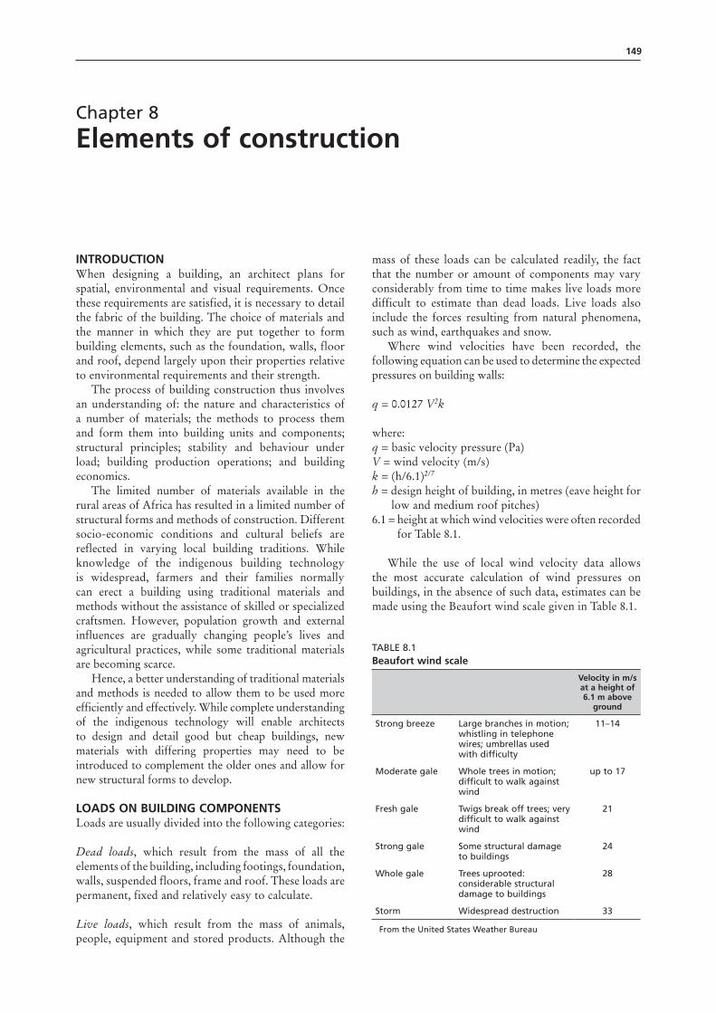
Where wind velocities have been recorded, the following equation can be used to determine the expected pressures on building walls:
q = 0.0127 V2k
where:q = basic velocity pressure (Pa)V = wind velocity (m/s) k = (h/6.1)2/7 h = design height of building, in metres (eave height for low and medium roof pitches) 6.1 = height at which wind velocities were often recorded for Table 8.1.
While the use of local wind velocity data allows the most accurate calculation of wind pressures on buildings, in the absence of such data, estimates can be made using the Beaufort wind scale given in Table 8.1.
Table 8.1beaufort wind scale
Velocity in m/s at a height of 6.1 m above
ground
Strong breeze large branches in motion; whistling in telephone wires; umbrellas used with difficulty
11–14
Moderate gale Whole trees in motion; difficult to walk against wind
up to 17
Fresh gale Twigs break off trees; very difficult to walk against wind
21
Strong gale Some structural damage to buildings
24
Whole gale Trees uprooted: considerable structural damage to buildings
28
Storm Widespread destruction 33
From the United States Weather bureau
150 Rural structures in the tropics: design and development
Some idea of the worst conditions to be expected can be formed by talking to long-time residents of the area.
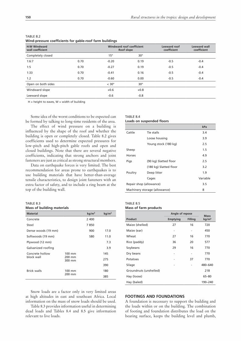
The effect of wind pressure on a building is influenced by the shape of the roof and whether the building is open or completely closed. Table 8.2 gives coefficients used to determine expected pressures for low-pitch and high-pitch gable roofs and open and closed buildings. Note that there are several negative coefficients, indicating that strong anchors and joint fasteners are just as critical as strong structural members.
Data on earthquake forces is very limited. The best recommendation for areas prone to earthquakes is to use building materials that have better-than-average tensile characteristics, to design joint fasteners with an extra factor of safety, and to include a ring beam at the top of the building wall.
Table 8.3mass of building materials
material kg/m3 kg/m2
Concrete 2 400
Steel 7 850
Dense woods (19 mm) 900 17.0
Softwoods (19 mm) 580 11.0
Plywood (12 mm) 7.3
Galvanized roofing 3.9
Concrete hollow block wall
100 mm 200 mm 300 mm
145
275
390
brick walls 100 mm 200 mm
180
385
Snow loads are a factor only in very limited areas at high altitudes in east and southeast Africa. Local information on the mass of snow loads should be used.
Table 8.3 provides information useful in determining dead loads and Tables 8.4 and 8.5 give information relevant to live loads.
Table 8.4Loads on suspended floors
kpa
Cattle Tie stalls 3.4
loose housing 3.9
Young stock (180 kg) 2.5
Sheep 1.5
Horses 4.9
Pigs (90 kg) Slatted floor 2.5
(180 kg) Slatted floor 3.2
Poultry Deep litter 1.9
Cages Variable
Repair shop (allowance) 3.5
Machinery storage (allowance) 8
Table 8.5mass of farm products
product
angle of reposemass kg/m³Emptying Filling
Maize (shelled) 27 16 720
Maize (ear) - - 450
Wheat 27 16 770
Rice (paddy) 36 20 577
Soybeans 29 16 770
Dry beans - - 770
Potatoes - 37 770
Silage - - 480–640
Groundnuts (unshelled) 218
Hay (loose) 65–80
Hay (baled) 190–240
FootIngs and FoundatIonsA foundation is necessary to support the building and the loads within or on the building. The combination of footing and foundation distributes the load on the bearing surface, keeps the building level and plumb,
Table 8.2Wind-pressure coefficients for gable-roof farm buildings
H:W Windward wall coefficient
Windward roof coefficient roof slope
Leeward roof coefficient
Leeward wall coefficient
Completely closed 15° 30°
1:6:7 0.70 -0.20 0.19 -0.5 -0.4
1:5 0.70 -0.27 0.19 -0.5 -0.4
1:33 0.70 -0.41 0.16 -0.5 -0.4
1.2 0.70 -0.60 0.00 -0.5 -0.4
Open on both sides < 30° 30°
Windward slope +0.6 +0.8
leeward slope -0.6 -0.8
H = height to eaves, W = width of building
151Chapter 8 – Elements of construction
and reduces settling to a minimum. When properly designed, there should be little or no cracking in the foundation, and no water leaks.
The footing and foundation should be made of a material that will not fail in the presence of ground or surface water. Before the footing for the foundation can be designed, it is necessary to determine the total load to be supported. If, for some reason, the load is concentrated in one or more areas, this will need to be taken into consideration. Once the load is determined, the soil-bearing characteristics of the site must be studied.
soil bearingThe top layer of soil is seldom suitable for a footing. The soil is likely to be loose, unstable and contain organic material. Consequently, the topsoil should be removed and the footing trench deepened to provide a level, undisturbed surface for the entire building foundation. If this is not feasible because of a sloping site, the footing will need to be stepped. This procedure is described later and illustrated in Figure 8.5.
The footing should never be placed on a filled area unless there has been sufficient time for consolidation. This usually takes at least one year with a normal amount of rainfall. The bearing capacity of soil is related to the soil type and the expected moisture level. Table 8.6 provides typical allowable soil-bearing values.
Table 8.6soil-bearing capacities
soil type kpa
Soft, wet, pasty or muddy soil 27–35
alluvial soil, loam, sandy loam (clay +40–70 percent sand)
80–160
Sandy clay loam (clay +30 percent sand), moist clay 215–270
Compact clay, nearly dry 215–270
Solid clay with very fine sand –430
Dry compact clay (thick layer) 320–540
loose sand 160–270
Compact sand 215–320
Red earth –320
Murram –430
Compact gravel 750–970
Rock –1700
An extensive investigation of the soil is not usually necessary for small-scale buildings. Foundation and pier footings can easily be designed to keep within the safe bearing capacity of the soil found on the building site.
site drainageIt is desirable to site any building on well drained land. However, other considerations such as access roads, water supply, existing services or a shortage of land may dictate the use of a poorly drained area.
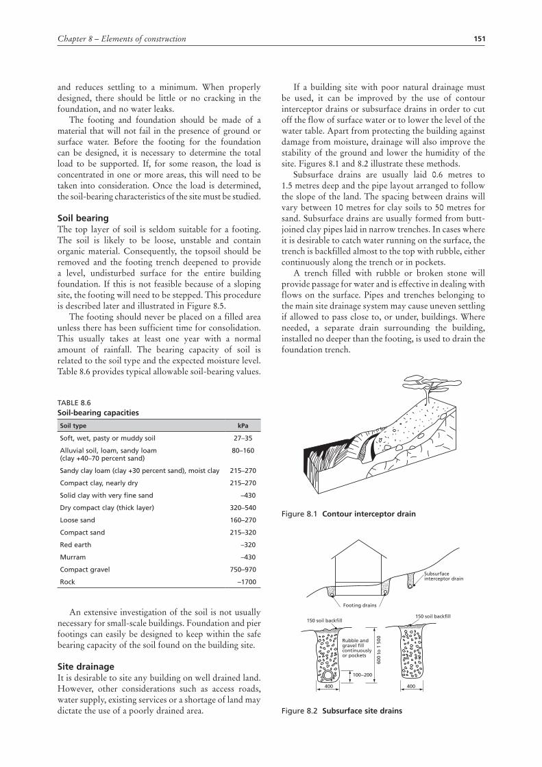
If a building site with poor natural drainage must be used, it can be improved by the use of contour interceptor drains or subsurface drains in order to cut off the flow of surface water or to lower the level of the water table. Apart from protecting the building against damage from moisture, drainage will also improve the stability of the ground and lower the humidity of the site. Figures 8.1 and 8.2 illustrate these methods.
Subsurface drains are usually laid 0.6 metres to 1.5 metres deep and the pipe layout arranged to follow the slope of the land. The spacing between drains will vary between 10 metres for clay soils to 50 metres for sand. Subsurface drains are usually formed from butt-joined clay pipes laid in narrow trenches. In cases where it is desirable to catch water running on the surface, the trench is backfilled almost to the top with rubble, either continuously along the trench or in pockets.
A trench filled with rubble or broken stone will provide passage for water and is effective in dealing with flows on the surface. Pipes and trenches belonging to the main site drainage system may cause uneven settling if allowed to pass close to, or under, buildings. Where needed, a separate drain surrounding the building, installed no deeper than the footing, is used to drain the foundation trench.
Figure 8.1 contour interceptor drain
Figure 8.2 subsurface site drains
400
100−200
600
to 1
500
Footing drains
Rubble andgravel fillcontinuouslyor pockets
Subsurfaceinterceptor drain
150 soil backfill150 soil backfill
400
152 Rural structures in the tropics: design and development
Foundation footingsA footing is an enlarged base for a foundation designed to distribute the building load over a larger area of soil and to provide a firm, level surface for constructing the foundation wall.
A foundation wall, regardless of the material used for its construction, should be built on a continuous footing of poured concrete. Although the footing will be covered, and lean mixes of concrete are considered satisfactory, a footing that is strong enough to resist cracking also helps to keep the foundation from cracking. A 1:3:5 ratio of cement–sand–gravel is suggested, with 31 litres of water per 50 kg sack of cement. The amount of water assumes dry aggregates. If the sand is damp, the water should be reduced by 4 litres to 5 litres.
The total area of the footing is determined by dividing the total load (including an estimated mass for the footing itself) by the bearing, by dividing the area by the length. In many cases the width required for light farm buildings will be equal to, or less than, the foundation wall planned.
In that case, a footing that is somewhat wider than the foundation is still recommended for at least two reasons. The footings conform to small variations in the trench and bridge small areas of loose soil, making a good surface on which to begin a foundation wall of any kind. The footings are easily made level, and this makes it easier to install the forms for a poured-concrete wall or to start the first course of a block or brick wall.
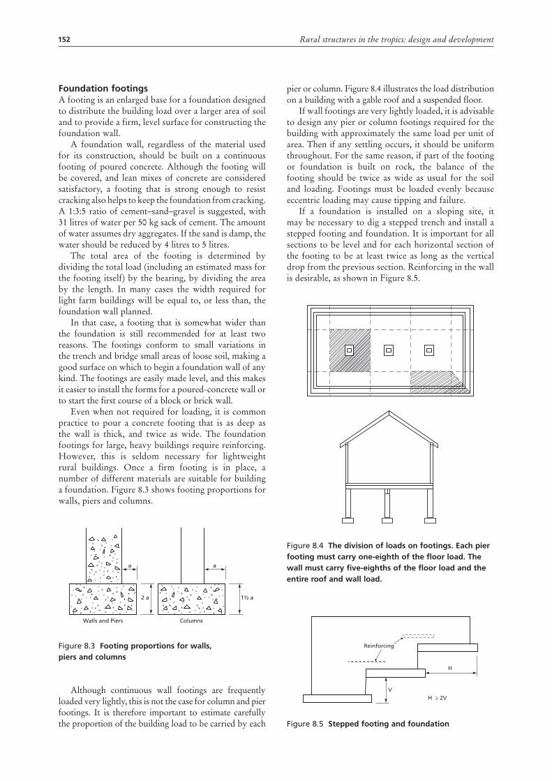
Even when not required for loading, it is common practice to pour a concrete footing that is as deep as the wall is thick, and twice as wide. The foundation footings for large, heavy buildings require reinforcing. However, this is seldom necessary for lightweight rural buildings. Once a firm footing is in place, a number of different materials are suitable for building a foundation. Figure 8.3 shows footing proportions for walls, piers and columns.
Figure 8.3 Footing proportions for walls, piers and columns
Although continuous wall footings are frequently loaded very lightly, this is not the case for column and pier footings. It is therefore important to estimate carefully the proportion of the building load to be carried by each
a a
1½ a2 a
Walls and Piers Columns
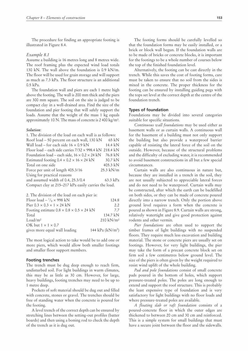
pier or column. Figure 8.4 illustrates the load distribution on a building with a gable roof and a suspended floor.
If wall footings are very lightly loaded, it is advisable to design any pier or column footings required for the building with approximately the same load per unit of area. Then if any settling occurs, it should be uniform throughout. For the same reason, if part of the footing or foundation is built on rock, the balance of the footing should be twice as wide as usual for the soil and loading. Footings must be loaded evenly because eccentric loading may cause tipping and failure.
If a foundation is installed on a sloping site, it may be necessary to dig a stepped trench and install a stepped footing and foundation. It is important for all sections to be level and for each horizontal section of the footing to be at least twice as long as the vertical drop from the previous section. Reinforcing in the wall is desirable, as shown in Figure 8.5.
Figure 8.4 the division of loads on footings. Each pier footing must carry one-eighth of the floor load. the wall must carry five-eighths of the floor load and the entire roof and wall load.
Figure 8.5 stepped footing and foundation
Reinforcing
V
H
H ≥ 2V
153Chapter 8 – Elements of construction
The procedure for finding an appropriate footing is illustrated in Figure 8.4.
Example 8.1Assume a building is 16 metres long and 8 metres wide. The roof framing plus the expected wind load totals 130 kN. The wall above the foundation is 0.9 kN/m. The floor will be used for grain storage and will support as much as 7.3 kPa. The floor structure is an additional 0.5 kPa.
The foundation wall and piers are each 1 metre high above the footing. The wall is 200 mm thick and the piers are 300 mm square. The soil on the site is judged to be compact clay in a well-drained area. Find the size of the foundation and pier footing that will safely support the loads. Assume that the weight of the mass 1 kg equals approximately 10 N. The mass of concrete is 2 400 kg/m³.
Solution:1. The division of the load on each wall is as follows:Roof load – 50 percent on each wall, 130 kN 65 kNWall load – for each side 16 × 0.9 kN 14.4 kNFloor load – each side carries 7/32 × 998.4 kN 218.4 kNFoundation load – each side, 16 × 0.2 × 24 kN 76.8 kNEstimated footing 0.4 × 0.2 × 16 × 24 kN 30.7 kNTotal on one side 405.3 kNForce per unit of length 405.3/16 25.3 kN/mUsing for practical reasonsand assumed width of 0.4, 25.3/0.4 63.3 kPa Compact clay at 215–217 kPa easily carries the load.
2. The division of the load on each pier is:Floor load – 1/8 × 998 kN 124.8Pier 0.3 × 0.3 × 1 × 24 kN 2.2Footing estimate 0.8 × 0.8 × 0.5 × 24 kN 7.7Total 134.7 kNLoad/m² 210 kN/m²OK but 1 × 1 × 0.7 gives more equal wall loading 144 kPa (kN/m2)
The most logical action to take would be to add one or more piers, which would allow both smaller footings and smaller floor support members.
Footing trenchesThe trench must be dug deep enough to reach firm, undisturbed soil. For light buildings in warm climates, this may be as little as 30 cm. However, for large, heavy buildings, footing trenches may need to be up to 1 metre deep.
Pockets of soft material should be dug out and filled with concrete, stones or gravel. The trenches should be free of standing water when the concrete is poured for the footing.
A level trench of the correct depth can be ensured by stretching lines between the setting-out profiles (batter boards) and then using a boning rod to check the depth of the trench as it is dug out.
The footing forms should be carefully levelled so that the foundation forms may be easily installed, or a brick or block wall begun. If the foundation walls are to be made of bricks or concrete blocks, it is important for the footings to be a whole number of courses below the top of the finished foundation level.
Alternatively, the footing can be cast directly in the trench. While this saves the cost of footing forms, care must be taken to ensure that no soil from the sides is mixed in the concrete. The proper thickness for the footing can be ensured by installing guiding pegs with the tops set level at the correct depth at the centre of the foundation trench.
types of foundationFoundations may be divided into several categories suitable for specific situations.
Continuous wall foundations may be used either as basement walls or as curtain walls. A continuous wall for the basement of a building must not only support the building but also provide a waterproof barrier capable of resisting the lateral force of the soil on the outside. However, because of the structural problems and the difficulty of excluding water, it is recommended to avoid basement constructions in all but a few special circumstances.
Curtain walls are also continuous in nature but, because they are installed in a trench in the soil, they are not usually subjected to appreciable lateral forces and do not need to be waterproof. Curtain walls may be constructed, after which the earth can be backfilled on both sides, or they can be made of concrete poured directly into a narrow trench. Only the portion above ground level requires a form when the concrete is poured as shown in Figure 8.9. Curtain walls are strong, relatively watertight and give good protection against rodents and other vermin.
Pier foundations are often used to support the timber frames of light buildings with no suspended floors. They require much less excavation and building material. The stone or concrete piers are usually set on footings. However, for very light buildings, the pier may take the form of a precast concrete block set on firm soil a few centimetres below ground level. The size of the piers is often given by the weight required to resist wind uplift of the whole building.
Pad and pole foundations consist of small concrete pads poured in the bottom of holes, which support pressure-treated poles. The poles are long enough to extend and support the roof structure. This is probably the least expensive type of foundation and is very satisfactory for light buildings with no floor loads and where pressure-treated poles are available.
A floating slab or raft foundation consists of a poured-concrete floor in which the outer edges are thickened to between 20 cm and 30 cm and reinforced. This is a simple system for small buildings that must have a secure joint between the floor and the sidewalls.
154 Rural structures in the tropics: design and development
A pier and ground-level beam foundation is commonly used where extensive filling has been necessary and the foundation would have to be very deep in order to reach undisturbed soil. It consists of a reinforced concrete beam supported on piers. The piers need to be deep enough to reach undisturbed soil and the beam must be embedded in the soil deeply enough to prevent rodents from burrowing under it. For very light buildings such as greenhouses, timber ground-level beams may be used.
Piles are long columns that are driven into soft ground where they support their load by friction with the soil rather than by a firm layer at their lower end. They are seldom used for farm buildings.
Foundation materialsThe foundation material should be at least as durable as the rest of the structure. Foundations are subject to attack by moisture, rodents, termites and, to a limited extent, wind. The moisture may come from rain, surface water or groundwater and, although a footing drain can reduce the problem, it is important to use a foundation material that will not be damaged by water or the lateral force created by saturated soil on the outside of the wall.
In some cases the foundation must be watertight in order to prevent water from penetrating into a basement or up through the foundation and into the building walls above. Any foundation should be continued for at least 150 mm above ground level to give adequate protection to the base of the wall from moisture, surface water, etc.
StonesStones are strong, durable and economical to use if they are available near the building site. Stones are suitable for low piers and curtain walls, where they may be laid up without mortar if economy is a major factor, although it is difficult to make them watertight, even if laid with mortar. Also, it is difficult to exclude termites from buildings with stone foundations because of the numerous passages between the stones. However, laying the top course or two in good, rich mortar and installing termite shields can overcome the termite problem to a large degree.
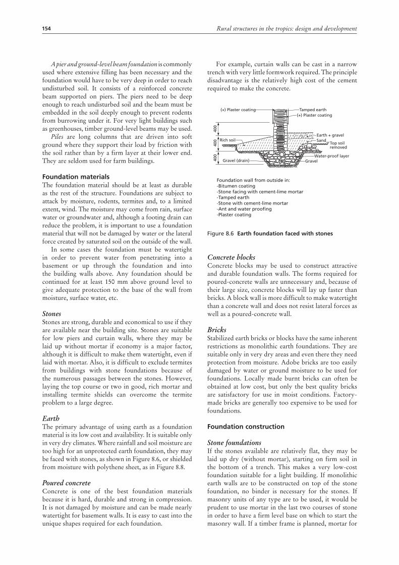
EarthThe primary advantage of using earth as a foundation material is its low cost and availability. It is suitable only in very dry climates. Where rainfall and soil moisture are too high for an unprotected earth foundation, they may be faced with stones, as shown in Figure 8.6, or shielded from moisture with polythene sheet, as in Figure 8.8.
Poured concreteConcrete is one of the best foundation materials because it is hard, durable and strong in compression. It is not damaged by moisture and can be made nearly watertight for basement walls. It is easy to cast into the unique shapes required for each foundation.
For example, curtain walls can be cast in a narrow trench with very little formwork required. The principle disadvantage is the relatively high cost of the cement required to make the concrete.
Figure 8.6 Earth foundation faced with stones
Concrete blocksConcrete blocks may be used to construct attractive and durable foundation walls. The forms required for poured-concrete walls are unnecessary and, because of their large size, concrete blocks will lay up faster than bricks. A block wall is more difficult to make watertight than a concrete wall and does not resist lateral forces as well as a poured-concrete wall.
BricksStabilized earth bricks or blocks have the same inherent restrictions as monolithic earth foundations. They are suitable only in very dry areas and even there they need protection from moisture. Adobe bricks are too easily damaged by water or ground moisture to be used for foundations. Locally made burnt bricks can often be obtained at low cost, but only the best quality bricks are satisfactory for use in moist conditions. Factory-made bricks are generally too expensive to be used for foundations.
Foundation construction
Stone foundationsIf the stones available are relatively flat, they may be laid up dry (without mortar), starting on firm soil in the bottom of a trench. This makes a very low-cost foundation suitable for a light building. If monolithic earth walls are to be constructed on top of the stone foundation, no binder is necessary for the stones. If masonry units of any type are to be used, it would be prudent to use mortar in the last two courses of stone in order to have a firm level base on which to start the masonry wall. If a timber frame is planned, mortar for
Rich soil
400
400
400
Gravel (drain)
(+) Plaster coating(+) Plaster coating
Earth + gravel
GravelWater-proof layer
Top soilremoved
Sand
Tamped earth
Foundation wall from outside in:-Bitumen coating-Stone facing with cement-lime mortar-Tamped earth-Stone with cement-lime mortar-Ant and water proofing-Plaster coating
155Chapter 8 – Elements of construction
the top courses, plus a metal termite shield, is necessary to provide a level surface and to exclude termites.
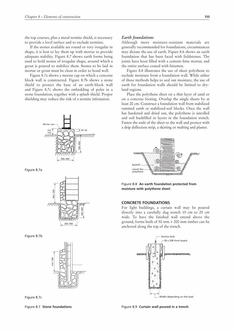
If the stones available are round or very irregular in shape, it is best to lay them up with mortar to provide adequate stability. Figure 8.7 shows earth forms being used to hold stones of irregular shape, around which a grout is poured to stabilize them. Stones to be laid in mortar or grout must be clean in order to bond well.
Figure 8.7a shows a mortar cap on which a concrete block wall is constructed. Figure 8.7b shows a stone shield to protect the base of an earth-block wall and Figure 8.7c shows the embedding of poles in a stone foundation, together with a splash shield. Proper shielding may reduce the risk of a termite infestation.
Figure 8.7a
Figure 8.7b
Figure 8.7c
Figure 8.7 stone foundations
Mortar cap
min.150
300−400
300−
400
30−50
Min
. 500
300−400
300−
400
min
. 500
Earth foundationsAlthough more moisture-resistant materials are generally recommended for foundations, circumstances may dictate the use of earth. Figure 8.6 shows an earth foundation that has been faced with fieldstones. The joints have been filled with a cement–lime mortar, and the entire surface coated with bitumen.
Figure 8.8 illustrates the use of sheet polythene to exclude moisture from a foundation wall. While either of these methods helps to seal out moisture, the use of earth for foundation walls should be limited to dry-land regions.
Place the polythene sheet on a thin layer of sand or on a concrete footing. Overlap the single sheets by at least 20 cm. Construct a foundation wall from stabilized rammed earth or stabilized-soil blocks. Once the wall has hardened and dried out, the polythene is unrolled and soil backfilled in layers in the foundation trench. Fasten the ends of the sheet to the wall and protect with a drip deflection strip, a skirting or malting and plaster.
Figure 8.8 an earth foundation protected from moisture with polythene sheet
concrEtE FoundatIonsFor light buildings, a curtain wall may be poured directly into a carefully dug trench 15 cm to 25 cm wide. To have the finished wall extend above the ground, forms built of 50 mm × 200 mm timber can be anchored along the top of the trench.
Figure 8.9 curtain wall poured in a trench
Backfill
Unroll thepolythene
50 x 200 form board
Width depending on the load
Anchor bolt
156 Rural structures in the tropics: design and development
A relatively lean 1:4:8 mix of concrete can be used. The concrete must be placed carefully to keep the walls of the trench from breaking off and mixing in, thereby causing weak spots. If the soil is not stable enough to allow digging of a trench form, a wide excavation and the use of simple forms will be required.
Additional information on ratios, materials, forms, placing and curing concrete is provided in Chapter 5.
Concrete-block foundationsIt is desirable for all dimensions of a block wall to be divisible by 225 mm. This allows full- or half-blocks to be used at all corners and openings without the need to cut blocks to odd lengths. Blocks must be dry when used because otherwise the mortar joints will not develop full strength.
Concrete block foundations should be started in a full bed of mortar on a poured-concrete footing. A 1:1:5 ratio of cement–lime–sand makes a good mortar. The corner blocks should be carefully located and checked for levelness and plumb. After several blocks have been laid adjacent to the corners, a line stretched between the corners can be used to align the top outside edge of each course of blocks.
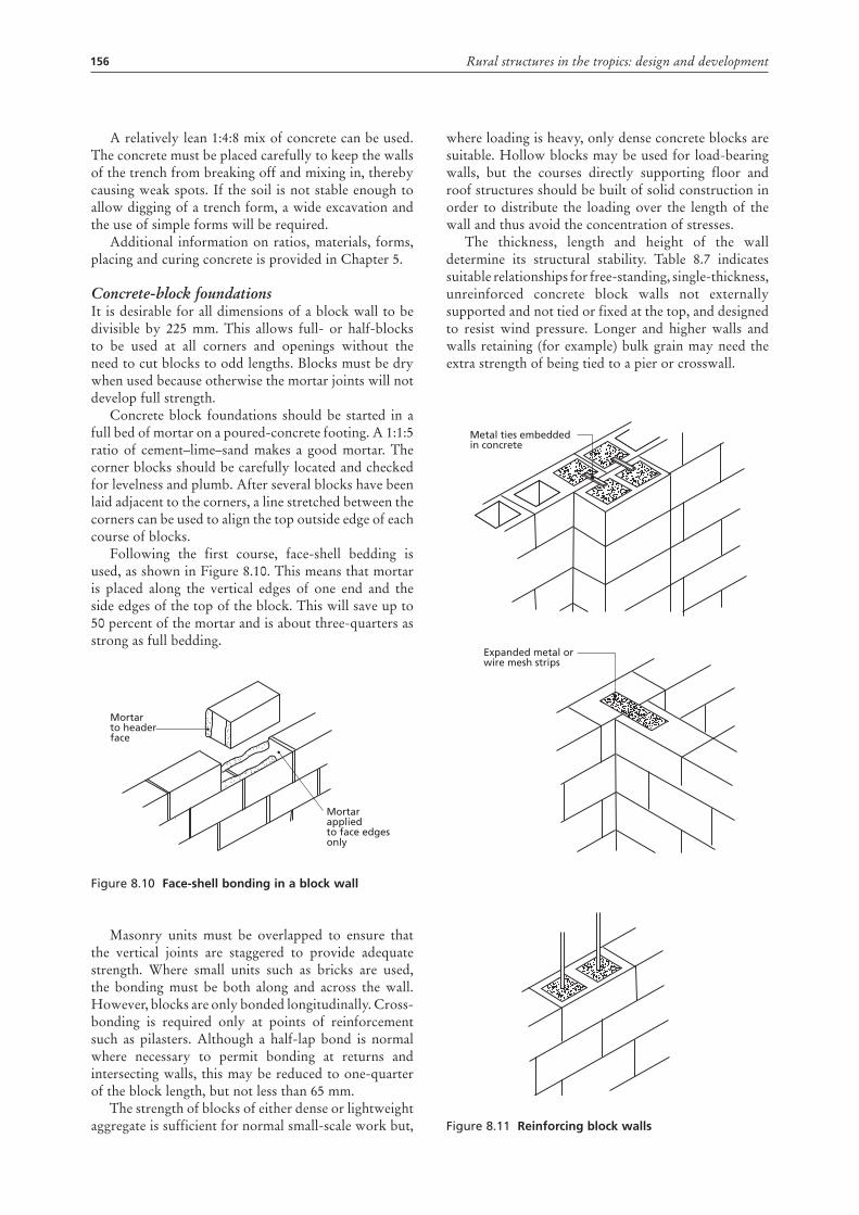
Following the first course, face-shell bedding is used, as shown in Figure 8.10. This means that mortar is placed along the vertical edges of one end and the side edges of the top of the block. This will save up to 50 percent of the mortar and is about three-quarters as strong as full bedding.
Figure 8.10 Face-shell bonding in a block wall
Masonry units must be overlapped to ensure that the vertical joints are staggered to provide adequate strength. Where small units such as bricks are used, the bonding must be both along and across the wall. However, blocks are only bonded longitudinally. Cross-bonding is required only at points of reinforcement such as pilasters. Although a half-lap bond is normal where necessary to permit bonding at returns and intersecting walls, this may be reduced to one-quarter of the block length, but not less than 65 mm.
The strength of blocks of either dense or lightweight aggregate is sufficient for normal small-scale work but,
Mortar to headerface
Mortar appliedto face edgesonly
where loading is heavy, only dense concrete blocks are suitable. Hollow blocks may be used for load-bearing walls, but the courses directly supporting floor and roof structures should be built of solid construction in order to distribute the loading over the length of the wall and thus avoid the concentration of stresses.
The thickness, length and height of the wall determine its structural stability. Table 8.7 indicates suitable relationships for free-standing, single-thickness, unreinforced concrete block walls not externally supported and not tied or fixed at the top, and designed to resist wind pressure. Longer and higher walls and walls retaining (for example) bulk grain may need the extra strength of being tied to a pier or crosswall.
Figure 8.11 reinforcing block walls
Metal ties embeddedin concrete
Expanded metal orwire mesh strips
157Chapter 8 – Elements of construction
Table 8.7stabilizing hollow-block walls
thickness of wall
Height of wall
maximum length of wall panel between piers, crosswalls, etc.
100 mm 1.8 metres 3.6 metres
150 mm 3.0 metres 3.0 metres
215 mm 3.6 metres 4.0 metres
215 mm 4.5 metres 3.0 metres
305 mm 4.5 metres 4.0 metres
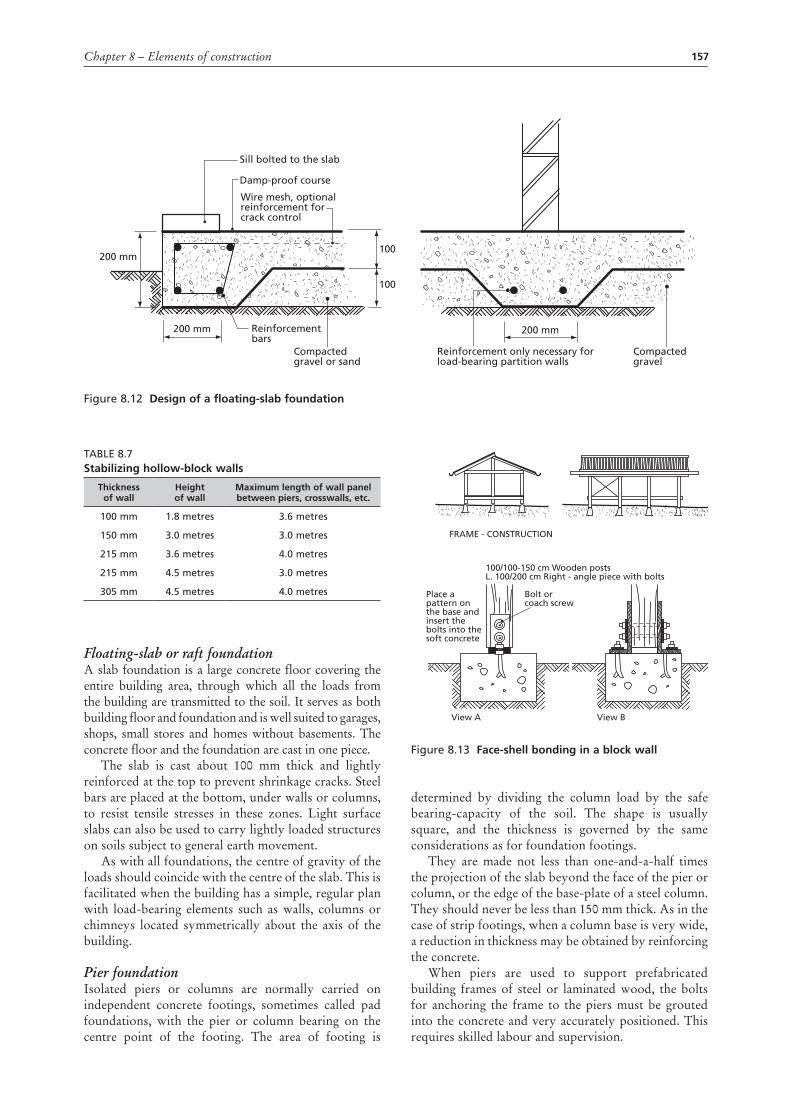
Floating-slab or raft foundationA slab foundation is a large concrete floor covering the entire building area, through which all the loads from the building are transmitted to the soil. It serves as both building floor and foundation and is well suited to garages, shops, small stores and homes without basements. The concrete floor and the foundation are cast in one piece.
The slab is cast about 100 mm thick and lightly reinforced at the top to prevent shrinkage cracks. Steel bars are placed at the bottom, under walls or columns, to resist tensile stresses in these zones. Light surface slabs can also be used to carry lightly loaded structures on soils subject to general earth movement.
As with all foundations, the centre of gravity of the loads should coincide with the centre of the slab. This is facilitated when the building has a simple, regular plan with load-bearing elements such as walls, columns or chimneys located symmetrically about the axis of the building.
Pier foundationIsolated piers or columns are normally carried on independent concrete footings, sometimes called pad foundations, with the pier or column bearing on the centre point of the footing. The area of footing is
determined by dividing the column load by the safe bearing-capacity of the soil. The shape is usually square, and the thickness is governed by the same considerations as for foundation footings.
They are made not less than one-and-a-half times the projection of the slab beyond the face of the pier or column, or the edge of the base-plate of a steel column. They should never be less than 150 mm thick. As in the case of strip footings, when a column base is very wide, a reduction in thickness may be obtained by reinforcing the concrete.
When piers are used to support prefabricated building frames of steel or laminated wood, the bolts for anchoring the frame to the piers must be grouted into the concrete and very accurately positioned. This requires skilled labour and supervision.
Figure 8.12 design of a floating-slab foundation
200 mm100
100
200 mm 200 mmReinforcement bars
Wire mesh, optionalreinforcement forcrack control
Damp-proof course
Sill bolted to the slab
Compactedgravel or sand
Reinforcement only necessary for load-bearing partition walls
Compactedgravel
Figure 8.13 Face-shell bonding in a block wall
FRAME - CONSTRUCTION
View A
Place apattern onthe base andinsert thebolts into thesoft concrete
Bolt orcoach screw
100/100-150 cm Wooden postsL. 100/200 cm Right - angle piece with bolts
View B
158 Rural structures in the tropics: design and development
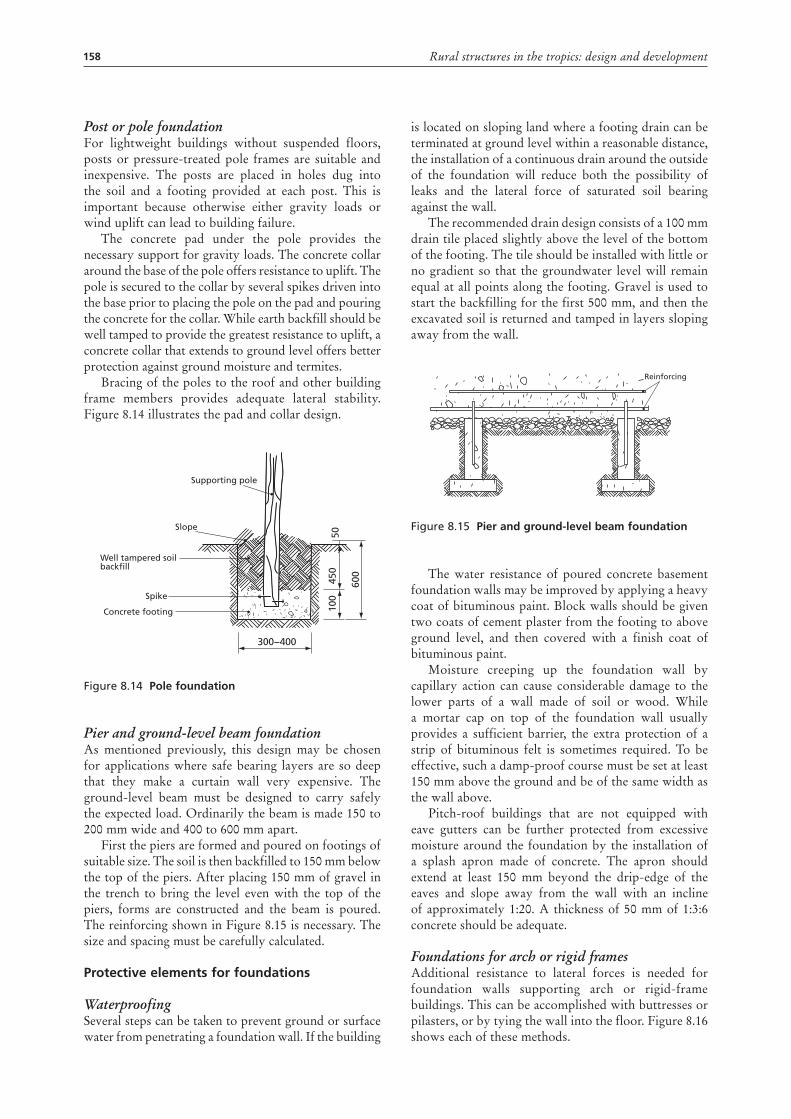
Post or pole foundationFor lightweight buildings without suspended floors, posts or pressure-treated pole frames are suitable and inexpensive. The posts are placed in holes dug into the soil and a footing provided at each post. This is important because otherwise either gravity loads or wind uplift can lead to building failure.
The concrete pad under the pole provides the necessary support for gravity loads. The concrete collar around the base of the pole offers resistance to uplift. The pole is secured to the collar by several spikes driven into the base prior to placing the pole on the pad and pouring the concrete for the collar. While earth backfill should be well tamped to provide the greatest resistance to uplift, a concrete collar that extends to ground level offers better protection against ground moisture and termites.
Bracing of the poles to the roof and other building frame members provides adequate lateral stability. Figure 8.14 illustrates the pad and collar design.
Figure 8.14 pole foundation
Pier and ground-level beam foundationAs mentioned previously, this design may be chosen for applications where safe bearing layers are so deep that they make a curtain wall very expensive. The ground-level beam must be designed to carry safely the expected load. Ordinarily the beam is made 150 to 200 mm wide and 400 to 600 mm apart.
First the piers are formed and poured on footings of suitable size. The soil is then backfilled to 150 mm below the top of the piers. After placing 150 mm of gravel in the trench to bring the level even with the top of the piers, forms are constructed and the beam is poured. The reinforcing shown in Figure 8.15 is necessary. The size and spacing must be carefully calculated.
protective elements for foundations
WaterproofingSeveral steps can be taken to prevent ground or surface water from penetrating a foundation wall. If the building
Supporting pole
Slope
Well tampered soilbackfill
300−400
100
450
50
600
Spike
Concrete footing
is located on sloping land where a footing drain can be terminated at ground level within a reasonable distance, the installation of a continuous drain around the outside of the foundation will reduce both the possibility of leaks and the lateral force of saturated soil bearing against the wall.
The recommended drain design consists of a 100 mm drain tile placed slightly above the level of the bottom of the footing. The tile should be installed with little or no gradient so that the groundwater level will remain equal at all points along the footing. Gravel is used to start the backfilling for the first 500 mm, and then the excavated soil is returned and tamped in layers sloping away from the wall.
Figure 8.15 pier and ground-level beam foundation
The water resistance of poured concrete basement foundation walls may be improved by applying a heavy coat of bituminous paint. Block walls should be given two coats of cement plaster from the footing to above ground level, and then covered with a finish coat of bituminous paint.
Moisture creeping up the foundation wall by capillary action can cause considerable damage to the lower parts of a wall made of soil or wood. While a mortar cap on top of the foundation wall usually provides a sufficient barrier, the extra protection of a strip of bituminous felt is sometimes required. To be effective, such a damp-proof course must be set at least 150 mm above the ground and be of the same width as the wall above.
Pitch-roof buildings that are not equipped with eave gutters can be further protected from excessive moisture around the foundation by the installation of a splash apron made of concrete. The apron should extend at least 150 mm beyond the drip-edge of the eaves and slope away from the wall with an incline of approximately 1:20. A thickness of 50 mm of 1:3:6 concrete should be adequate.
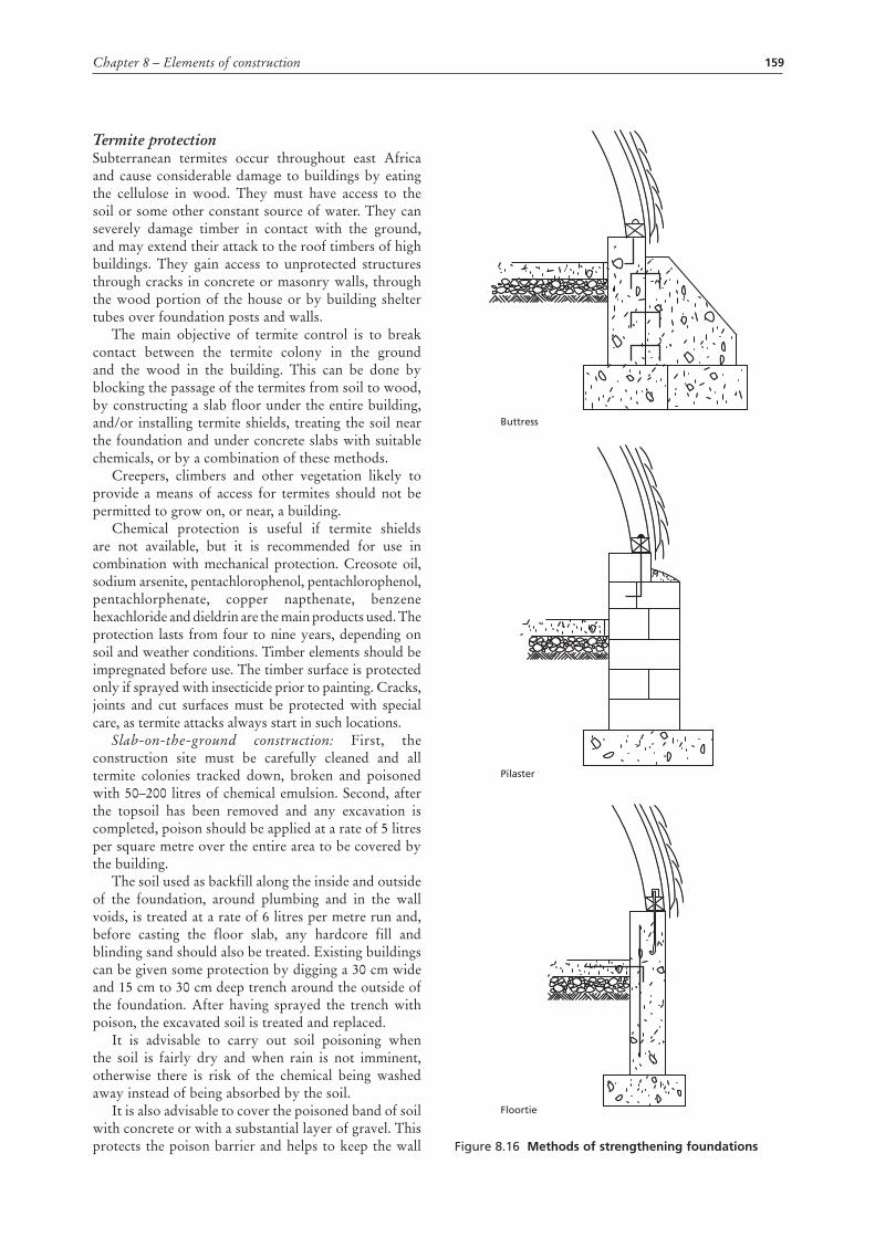
Foundations for arch or rigid framesAdditional resistance to lateral forces is needed for foundation walls supporting arch or rigid-frame buildings. This can be accomplished with buttresses or pilasters, or by tying the wall into the floor. Figure 8.16 shows each of these methods.
Reinforcing
159Chapter 8 – Elements of construction
Termite protectionSubterranean termites occur throughout east Africa and cause considerable damage to buildings by eating the cellulose in wood. They must have access to the soil or some other constant source of water. They can severely damage timber in contact with the ground, and may extend their attack to the roof timbers of high buildings. They gain access to unprotected structures through cracks in concrete or masonry walls, through the wood portion of the house or by building shelter tubes over foundation posts and walls.
The main objective of termite control is to break contact between the termite colony in the ground and the wood in the building. This can be done by blocking the passage of the termites from soil to wood, by constructing a slab floor under the entire building, and/or installing termite shields, treating the soil near the foundation and under concrete slabs with suitable chemicals, or by a combination of these methods.
Creepers, climbers and other vegetation likely to provide a means of access for termites should not be permitted to grow on, or near, a building.
Chemical protection is useful if termite shields are not available, but it is recommended for use in combination with mechanical protection. Creosote oil, sodium arsenite, pentachlorophenol, pentachlorophenol, pentachlorphenate, copper napthenate, benzene hexachloride and dieldrin are the main products used. The protection lasts from four to nine years, depending on soil and weather conditions. Timber elements should be impregnated before use. The timber surface is protected only if sprayed with insecticide prior to painting. Cracks, joints and cut surfaces must be protected with special care, as termite attacks always start in such locations.
Slab-on-the-ground construction: First, the construction site must be carefully cleaned and all termite colonies tracked down, broken and poisoned with 50–200 litres of chemical emulsion. Second, after the topsoil has been removed and any excavation is completed, poison should be applied at a rate of 5 litres per square metre over the entire area to be covered by the building.
The soil used as backfill along the inside and outside of the foundation, around plumbing and in the wall voids, is treated at a rate of 6 litres per metre run and, before casting the floor slab, any hardcore fill and blinding sand should also be treated. Existing buildings can be given some protection by digging a 30 cm wide and 15 cm to 30 cm deep trench around the outside of the foundation. After having sprayed the trench with poison, the excavated soil is treated and replaced.
It is advisable to carry out soil poisoning when the soil is fairly dry and when rain is not imminent, otherwise there is risk of the chemical being washed away instead of being absorbed by the soil.
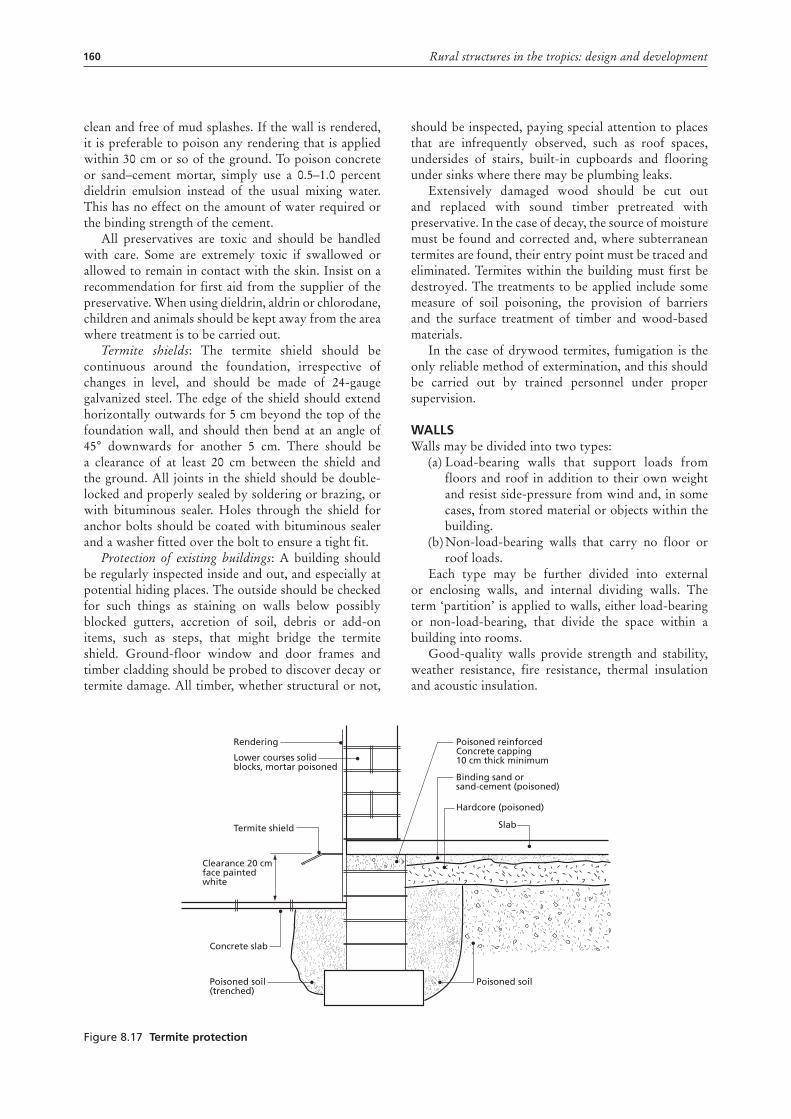
It is also advisable to cover the poisoned band of soil with concrete or with a substantial layer of gravel. This protects the poison barrier and helps to keep the wall
Buttress
Pilaster
Floortie
Figure 8.16 methods of strengthening foundations
160 Rural structures in the tropics: design and development
clean and free of mud splashes. If the wall is rendered, it is preferable to poison any rendering that is applied within 30 cm or so of the ground. To poison concrete or sand–cement mortar, simply use a 0.5–1.0 percent dieldrin emulsion instead of the usual mixing water. This has no effect on the amount of water required or the binding strength of the cement.
All preservatives are toxic and should be handled with care. Some are extremely toxic if swallowed or allowed to remain in contact with the skin. Insist on a recommendation for first aid from the supplier of the preservative. When using dieldrin, aldrin or chlorodane, children and animals should be kept away from the area where treatment is to be carried out.
Termite shields: The termite shield should be continuous around the foundation, irrespective of changes in level, and should be made of 24-gauge galvanized steel. The edge of the shield should extend horizontally outwards for 5 cm beyond the top of the foundation wall, and should then bend at an angle of 45° downwards for another 5 cm. There should be a clearance of at least 20 cm between the shield and the ground. All joints in the shield should be double-locked and properly sealed by soldering or brazing, or with bituminous sealer. Holes through the shield for anchor bolts should be coated with bituminous sealer and a washer fitted over the bolt to ensure a tight fit.
Protection of existing buildings: A building should be regularly inspected inside and out, and especially at potential hiding places. The outside should be checked for such things as staining on walls below possibly blocked gutters, accretion of soil, debris or add-on items, such as steps, that might bridge the termite shield. Ground-floor window and door frames and timber cladding should be probed to discover decay or termite damage. All timber, whether structural or not,
should be inspected, paying special attention to places that are infrequently observed, such as roof spaces, undersides of stairs, built-in cupboards and flooring under sinks where there may be plumbing leaks.
Extensively damaged wood should be cut out and replaced with sound timber pretreated with preservative. In the case of decay, the source of moisture must be found and corrected and, where subterranean termites are found, their entry point must be traced and eliminated. Termites within the building must first be destroyed. The treatments to be applied include some measure of soil poisoning, the provision of barriers and the surface treatment of timber and wood-based materials.
In the case of drywood termites, fumigation is the only reliable method of extermination, and this should be carried out by trained personnel under proper supervision.
WaLLsWalls may be divided into two types:
(a) Load-bearing walls that support loads from floors and roof in addition to their own weight and resist side-pressure from wind and, in some cases, from stored material or objects within the building.
(b) Non-load-bearing walls that carry no floor or roof loads.
Each type may be further divided into external or enclosing walls, and internal dividing walls. The term ‘partition’ is applied to walls, either load-bearing or non-load-bearing, that divide the space within a building into rooms.
Good-quality walls provide strength and stability, weather resistance, fire resistance, thermal insulation and acoustic insulation.
Figure 8.17 termite protection
Rendering
Lower courses solidblocks, mortar poisoned
Termite shield
Clearance 20 cmface paintedwhite
Concrete slab
Slab
Poisoned soil(trenched)
Poisoned soil
Poisoned reinforcedConcrete capping10 cm thick minimum
Binding sand orsand-cement (poisoned)
Hardcore (poisoned)
161Chapter 8 – Elements of construction
types of building wallWhile there are various ways to construct a wall and many different materials can be used, walls can be divided into four main groups.
Masonry walls, where the wall is built of individual blocks of materials such as brick, clay, concrete block or stone, usually in horizontal courses bonded together with some form of mortar. Several earth-derived products, either air-dried or fired, are reasonable in cost and well suited to the climate.
Monolithic walls, where the wall is built of a material placed in forms during construction. The traditional earth wall and the modern concrete wall are examples. Earth walls are inexpensive and durable if placed on a good foundation and protected from rain by rendering or wide roof overhangs.
Frame walls, where the wall is constructed as a frame of relatively small members, usually of timber, at close intervals, which, together with facing or sheathing on one or both sides, form a load-bearing system. Offcuts are a low-cost material to use for a frame-wall covering.
Membrane walls, where the wall is constructed as a sandwich of two thin skins or sheets of reinforced plastic, metal, asbestos cement or other suitable material bonded to a core of foamed plastic to produce a thin wall element with high strength and low weight.
Another form of construction suitable for framed or earth buildings consists of relatively light sheeting secured to the face of the wall to form the enclosed element. These are generally termed ‘claddings’.
Factors that determine the type of wall to be used are:
• the materials available at a reasonable cost; • the availability of craft workers capable of using
the materials in the best way; • climate;• the use of the building and functional requirements.
The height of walls should allow people to walk freely and work in a room without knocking their heads on the ceiling, beams, etc. In dwellings with ceilings, 2.4 metres is a suitable height. Low roofs or ceilings in a house create a depressing atmosphere and tend to make the rooms warmer in hot weather.
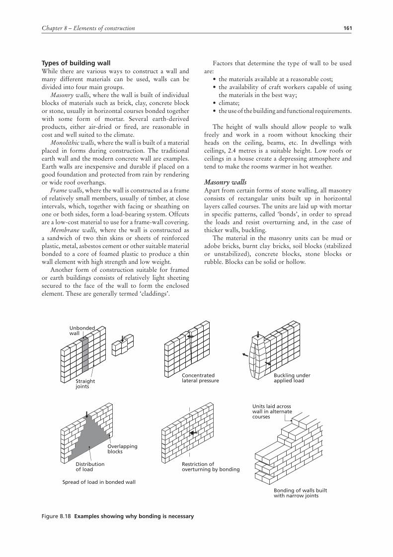
Masonry wallsApart from certain forms of stone walling, all masonry consists of rectangular units built up in horizontal layers called courses. The units are laid up with mortar in specific patterns, called ‘bonds’, in order to spread the loads and resist overturning and, in the case of thicker walls, buckling.
The material in the masonry units can be mud or adobe bricks, burnt clay bricks, soil blocks (stabilized or unstabilized), concrete blocks, stone blocks or rubble. Blocks can be solid or hollow.
Figure 8.18 Examples showing why bonding is necessary
Unbondedwall
Overlappingblocks
Distributionof load
Straightjoints
Concentratedlateral pressure
Buckling underapplied load
Units laid across wall in alternate courses
Bonding of walls built with narrow joints
Restriction ofoverturning by bonding
Spread of load in bonded wall
162 Rural structures in the tropics: design and development
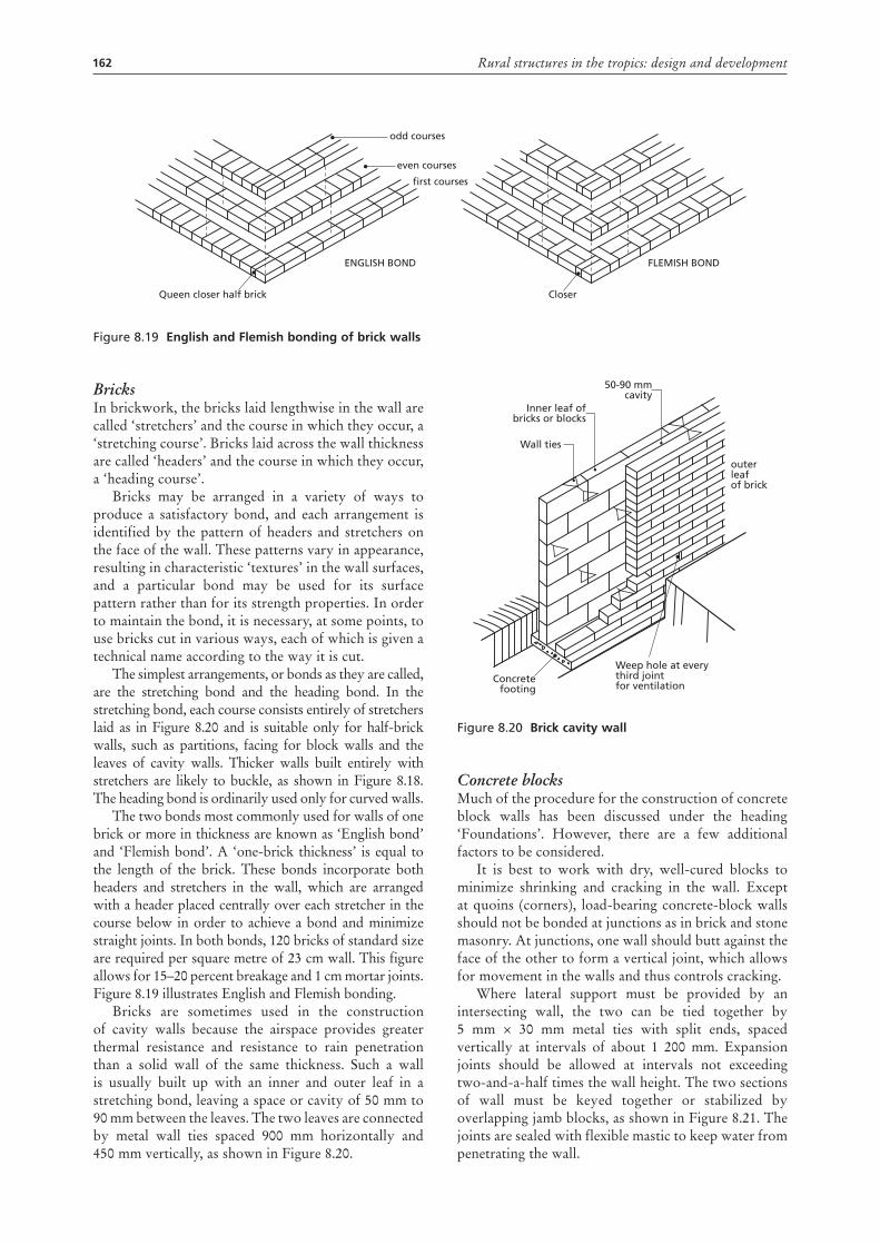
BricksIn brickwork, the bricks laid lengthwise in the wall are called ‘stretchers’ and the course in which they occur, a ‘stretching course’. Bricks laid across the wall thickness are called ‘headers’ and the course in which they occur, a ‘heading course’.
Bricks may be arranged in a variety of ways to produce a satisfactory bond, and each arrangement is identified by the pattern of headers and stretchers on the face of the wall. These patterns vary in appearance, resulting in characteristic ‘textures’ in the wall surfaces, and a particular bond may be used for its surface pattern rather than for its strength properties. In order to maintain the bond, it is necessary, at some points, to use bricks cut in various ways, each of which is given a technical name according to the way it is cut.
The simplest arrangements, or bonds as they are called, are the stretching bond and the heading bond. In the stretching bond, each course consists entirely of stretchers laid as in Figure 8.20 and is suitable only for half-brick walls, such as partitions, facing for block walls and the leaves of cavity walls. Thicker walls built entirely with stretchers are likely to buckle, as shown in Figure 8.18. The heading bond is ordinarily used only for curved walls.
The two bonds most commonly used for walls of one brick or more in thickness are known as ‘English bond’ and ‘Flemish bond’. A ‘one-brick thickness’ is equal to the length of the brick. These bonds incorporate both headers and stretchers in the wall, which are arranged with a header placed centrally over each stretcher in the course below in order to achieve a bond and minimize straight joints. In both bonds, 120 bricks of standard size are required per square metre of 23 cm wall. This figure allows for 15–20 percent breakage and 1 cm mortar joints. Figure 8.19 illustrates English and Flemish bonding.
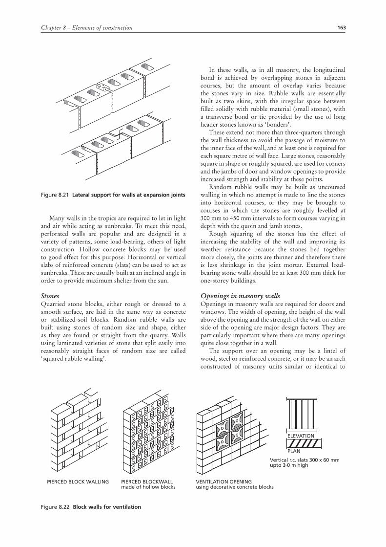
Bricks are sometimes used in the construction of cavity walls because the airspace provides greater thermal resistance and resistance to rain penetration than a solid wall of the same thickness. Such a wall is usually built up with an inner and outer leaf in a stretching bond, leaving a space or cavity of 50 mm to 90 mm between the leaves. The two leaves are connected by metal wall ties spaced 900 mm horizontally and 450 mm vertically, as shown in Figure 8.20.
Figure 8.20 brick cavity wall
Concrete blocksMuch of the procedure for the construction of concrete block walls has been discussed under the heading ‘Foundations’. However, there are a few additional factors to be considered.
It is best to work with dry, well-cured blocks to minimize shrinking and cracking in the wall. Except at quoins (corners), load-bearing concrete-block walls should not be bonded at junctions as in brick and stone masonry. At junctions, one wall should butt against the face of the other to form a vertical joint, which allows for movement in the walls and thus controls cracking.
Where lateral support must be provided by an intersecting wall, the two can be tied together by 5 mm × 30 mm metal ties with split ends, spaced vertically at intervals of about 1 200 mm. Expansion joints should be allowed at intervals not exceeding two-and-a-half times the wall height. The two sections of wall must be keyed together or stabilized by overlapping jamb blocks, as shown in Figure 8.21. The joints are sealed with flexible mastic to keep water from penetrating the wall.
Wall ties
Concretefooting
Weep hole at everythird jointfor ventilation
outerleafof brick
Inner leaf ofbricks or blocks
50-90 mmcavity
Figure 8.19 English and Flemish bonding of brick walls
Queen closer half brick Closer
odd courses
even courses
first courses
ENGLISH BOND FLEMISH BOND
163Chapter 8 – Elements of construction
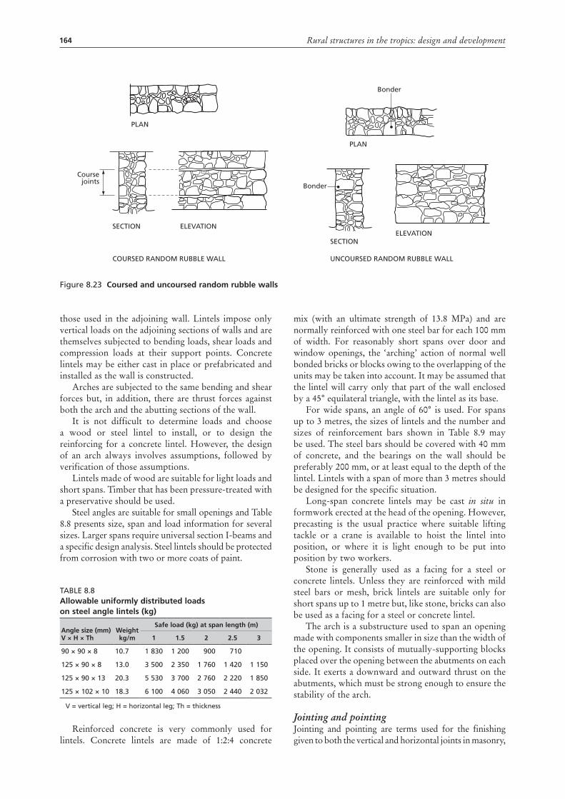
Figure 8.21 Lateral support for walls at expansion joints
Many walls in the tropics are required to let in light and air while acting as sunbreaks. To meet this need, perforated walls are popular and are designed in a variety of patterns, some load-bearing, others of light construction. Hollow concrete blocks may be used to good effect for this purpose. Horizontal or vertical slabs of reinforced concrete (slats) can be used to act as sunbreaks. These are usually built at an inclined angle in order to provide maximum shelter from the sun.
StonesQuarried stone blocks, either rough or dressed to a smooth surface, are laid in the same way as concrete or stabilized-soil blocks. Random rubble walls are built using stones of random size and shape, either as they are found or straight from the quarry. Walls using laminated varieties of stone that split easily into reasonably straight faces of random size are called ‘squared rubble walling’.
In these walls, as in all masonry, the longitudinal bond is achieved by overlapping stones in adjacent courses, but the amount of overlap varies because the stones vary in size. Rubble walls are essentially built as two skins, with the irregular space between filled solidly with rubble material (small stones), with a transverse bond or tie provided by the use of long header stones known as ‘bonders’.
These extend not more than three-quarters through the wall thickness to avoid the passage of moisture to the inner face of the wall, and at least one is required for each square metre of wall face. Large stones, reasonably square in shape or roughly squared, are used for corners and the jambs of door and window openings to provide increased strength and stability at these points.
Random rubble walls may be built as uncoursed walling in which no attempt is made to line the stones into horizontal courses, or they may be brought to courses in which the stones are roughly levelled at 300 mm to 450 mm intervals to form courses varying in depth with the quoin and jamb stones.
Rough squaring of the stones has the effect of increasing the stability of the wall and improving its weather resistance because the stones bed together more closely, the joints are thinner and therefore there is less shrinkage in the joint mortar. External load-bearing stone walls should be at least 300 mm thick for one-storey buildings.
Openings in masonry wallsOpenings in masonry walls are required for doors and windows. The width of opening, the height of the wall above the opening and the strength of the wall on either side of the opening are major design factors. They are particularly important where there are many openings quite close together in a wall.
The support over an opening may be a lintel of wood, steel or reinforced concrete, or it may be an arch constructed of masonry units similar or identical to
Figure 8.22 block walls for ventilation
PIERCED BLOCK WALLING PIERCED BLOCKWALLmade of hollow blocks
VENTILATION OPENINGusing decorative concrete blocks
Vertical r.c. slats 300 x 60 mmupto 3∙0 m high
ELEVATION
PLAN
164 Rural structures in the tropics: design and development
those used in the adjoining wall. Lintels impose only vertical loads on the adjoining sections of walls and are themselves subjected to bending loads, shear loads and compression loads at their support points. Concrete lintels may be either cast in place or prefabricated and installed as the wall is constructed.
Arches are subjected to the same bending and shear forces but, in addition, there are thrust forces against both the arch and the abutting sections of the wall.
It is not difficult to determine loads and choose a wood or steel lintel to install, or to design the reinforcing for a concrete lintel. However, the design of an arch always involves assumptions, followed by verification of those assumptions.
Lintels made of wood are suitable for light loads and short spans. Timber that has been pressure-treated with a preservative should be used.
Steel angles are suitable for small openings and Table 8.8 presents size, span and load information for several sizes. Larger spans require universal section I-beams and a specific design analysis. Steel lintels should be protected from corrosion with two or more coats of paint.
Table 8.8allowable uniformly distributed loads on steel angle lintels (kg)
angle size (mm) V × H × th
Weight kg/m
safe load (kg) at span length (m)
1 1.5 2 2.5 3
90 × 90 × 8 10.7 1 830 1 200 900 710
125 × 90 × 8 13.0 3 500 2 350 1 760 1 420 1 150
125 × 90 × 13 20.3 5 530 3 700 2 760 2 220 1 850
125 × 102 × 10 18.3 6 100 4 060 3 050 2 440 2 032
V = vertical leg; H = horizontal leg; Th = thickness
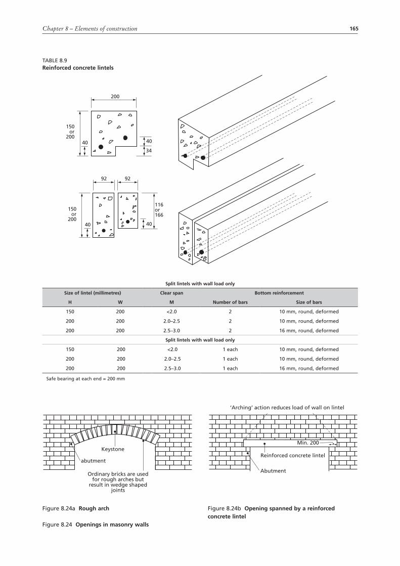
Reinforced concrete is very commonly used for lintels. Concrete lintels are made of 1:2:4 concrete
mix (with an ultimate strength of 13.8 MPa) and are normally reinforced with one steel bar for each 100 mm of width. For reasonably short spans over door and window openings, the ‘arching’ action of normal well bonded bricks or blocks owing to the overlapping of the units may be taken into account. It may be assumed that the lintel will carry only that part of the wall enclosed by a 45° equilateral triangle, with the lintel as its base.
For wide spans, an angle of 60° is used. For spans up to 3 metres, the sizes of lintels and the number and sizes of reinforcement bars shown in Table 8.9 may be used. The steel bars should be covered with 40 mm of concrete, and the bearings on the wall should be preferably 200 mm, or at least equal to the depth of the lintel. Lintels with a span of more than 3 metres should be designed for the specific situation.
Long-span concrete lintels may be cast in situ in formwork erected at the head of the opening. However, precasting is the usual practice where suitable lifting tackle or a crane is available to hoist the lintel into position, or where it is light enough to be put into position by two workers.
Stone is generally used as a facing for a steel or concrete lintels. Unless they are reinforced with mild steel bars or mesh, brick lintels are suitable only for short spans up to 1 metre but, like stone, bricks can also be used as a facing for a steel or concrete lintel.
The arch is a substructure used to span an opening made with components smaller in size than the width of the opening. It consists of mutually-supporting blocks placed over the opening between the abutments on each side. It exerts a downward and outward thrust on the abutments, which must be strong enough to ensure the stability of the arch.
Jointing and pointingJointing and pointing are terms used for the finishing given to both the vertical and horizontal joints in masonry,
Figure 8.23 coursed and uncoursed random rubble walls
PLAN
PLAN
Bonder
Bonder
Coursejoints
SECTION
COURSED RANDOM RUBBLE WALL UNCOURSED RANDOM RUBBLE WALL
SECTION
ELEVATIONELEVATION
165Chapter 8 – Elements of construction
Table 8.9reinforced concrete lintels
150or
200
200
40
40
34
40
40
92 92
150or
200
116or166
split lintels with wall load only
size of lintel (millimetres) clear span bottom reinforcement
H W m number of bars size of bars
150 200 <2.0 2 10 mm, round, deformed
200 200 2.0–2.5 2 10 mm, round, deformed
200 200 2.5–3.0 2 16 mm, round, deformed
split lintels with wall load only
150 200 <2.0 1 each 10 mm, round, deformed
200 200 2.0–2.5 1 each 10 mm, round, deformed
200 200 2.5–3.0 1 each 16 mm, round, deformed
Safe bearing at each end = 200 mm
Figure 8.24a rough arch
Figure 8.24 openings in masonry walls
abutment
Keystone
Ordinary bricks are usedfor rough arches but
result in wedge shapedjoints
Figure 8.24b opening spanned by a reinforced concrete lintel
Abutment
Reinforced concrete lintel
Min. 200
‘Arching’ action reduces load of wall on lintel
166 Rural structures in the tropics: design and development
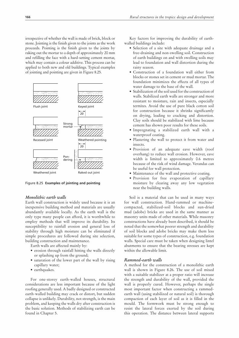
irrespective of whether the wall is made of brick, block or stone. Jointing is the finish given to the joints as the work proceeds. Pointing is the finish given to the joints by raking out the mortar to a depth of approximately 20 mm and refilling the face with a hard-setting cement mortar, which may contain a colour additive. This process can be applied to both new and old buildings. Typical examples of jointing and pointing are given in Figure 8.25.
Figure 8.25 Examples of jointing and pointing
Monolithic earth wallsEarth wall construction is widely used because it is an inexpensive building method and materials are usually abundantly available locally. As the earth wall is the only type many people can afford, it is worthwhile to employ methods that will improve its durability. Its susceptibility to rainfall erosion and general loss of stability through high moisture can be eliminated if simple procedures are followed during site selection, building construction and maintenance.
Earth walls are affected mainly by:• erosion through rainfall hitting the walls directly
or splashing up from the ground; • saturation of the lower part of the wall by rising
capillary water; • earthquakes.
For one-storey earth-walled houses, structural considerations are less important because of the light roofing generally used. A badly designed or constructed earth-walled building may crack or distort, but sudden collapse is unlikely. Durability, not strength, is the main problem, and keeping the walls dry after construction is the basic solution. Methods of stabilizing earth can be found in Chapter 5.
Flush joint
Recessed joint
Weathered joint
Keyed joint
Weathered pointing
20
Raked out joint
Pon-dering
Strongmortar
20
Key factors for improving the durability of earth-walled buildings include:
• Selection of a site with adequate drainage and a free-draining and non-swelling soil. Construction of earth buildings on and with swelling soils may lead to foundation and wall distortion during the rainy season.
• Construction of a foundation wall either from blocks or stones set in cement or mud mortar. The foundation minimizes the effects of all types of water damage to the base of the wall.
• Stabilization of the soil used for the construction of walls. Stabilized earth walls are stronger and more resistant to moisture, rain and insects, especially termites. Avoid the use of pure black cotton soil for construction because it shrinks significantly on drying, leading to cracking and distortion. Clay soils should be stabilized with lime because cement has shown poor results for these soils.
• Impregnating a stabilized earth wall with a waterproof coating.
• Plastering the wall to protect it from water and insects.
• Provision of an adequate eave width (roof overhang) to reduce wall erosion. However, eave width is limited to approximately 0.6 metres because of the risk of wind damage. Verandas can be useful for wall protection.
• Maintenance of the wall and protective coating. • Provision for free evaporation of capillary
moisture by clearing away any low vegetation near the building walls.
Soil is a material that can be used in many ways for wall construction. Hand-rammed or machine-compacted, stabilized-soil blocks and sun-dried mud (adobe) bricks are used in the same manner as masonry units made of other materials. While masonry constructions have already been described, it should be noted that the somewhat poorer strength and durability of soil blocks and adobe bricks may make them less suitable for some types of construction, e.g. foundation walls. Special care must be taken when designing lintel abutments to ensure that the bearing stresses are kept within the allowable limit.
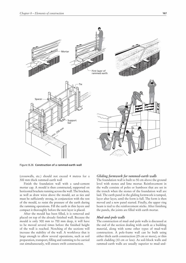
Rammed-earth wallsA method for the construction of a monolithic earth wall is shown in Figure 8.26. The use of soil mixed with a suitable stabilizer at a proper ratio will increase the strength and durability of the wall, provided the wall is properly cured. However, perhaps the single most important factor when constructing a rammed-earth wall (using stabilized or natural soil) is thorough compaction of each layer of soil as it is filled in the mould. The formwork must be strong enough to resist the lateral forces exerted by the soil during this operation. The distance between lateral supports
167Chapter 8 – Elements of construction
(crosswalls, etc.) should not exceed 4 metres for a 300 mm thick rammed-earth wall
Finish the foundation wall with a sand–cement mortar cap. A mould is then constructed, supported on horizontal brackets running across the wall. The brackets, as well as draw wires above the mould, act as ties and must be sufficiently strong, in conjunction with the rest of the mould, to resist the pressure of the earth during the ramming operations. Fill the earth in thin layers and compact it thoroughly before the next layer is placed.
After the mould has been filled, it is removed and placed on top of the already finished wall. Because the mould is only 500 mm to 700 mm deep, it will have to be moved several times before the finished height of the wall is reached. Notching of the sections will increase the stability of the wall. A workforce that is large enough to allow several operations, such as soil preparation, transport, filling and ramming to be carried out simultaneously, will ensure swift construction.
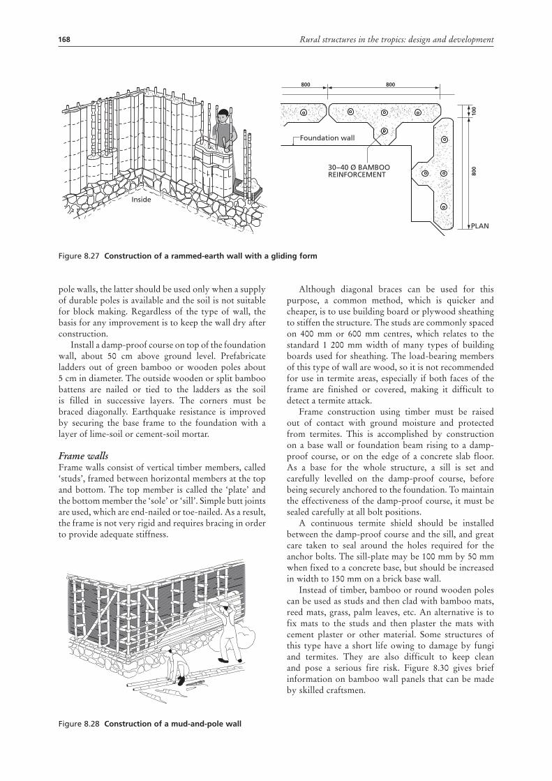
Gliding formwork for rammed-earth wallsThe foundation wall is built to 50 cm above the ground level with stones and lime mortar. Reinforcement in the walls consists of poles or bamboos that are set in the trench when the stones of the foundation wall are laid. The earth panel in the gliding formwork is tamped, layer after layer, until the form is full. The form is then moved and a new panel started. Finally, the upper ring beam is tied to the reinforcement sticks. After finishing the panels, the joints are filled with earth mortar.
Mud-and-pole wallsThe construction of mud-and-pole walls is discussed at the end of the section dealing with earth as a building material, along with some other types of mud-wall construction. A pole-frame wall can be built using either thick earth construction (25 cm or more), or thin earth cladding (10 cm or less). As soil-block walls and rammed-earth walls are usually superior to mud-and-
Figure 8.26 construction of a rammed-earth wall
Mortar
First layer of rammed earth
Spacer
Tie
min. 250 m
m
Support bar
168 Rural structures in the tropics: design and development
pole walls, the latter should be used only when a supply of durable poles is available and the soil is not suitable for block making. Regardless of the type of wall, the basis for any improvement is to keep the wall dry after construction.
Install a damp-proof course on top of the foundation wall, about 50 cm above ground level. Prefabricate ladders out of green bamboo or wooden poles about 5 cm in diameter. The outside wooden or split bamboo battens are nailed or tied to the ladders as the soil is filled in successive layers. The corners must be braced diagonally. Earthquake resistance is improved by securing the base frame to the foundation with a layer of lime-soil or cement-soil mortar.
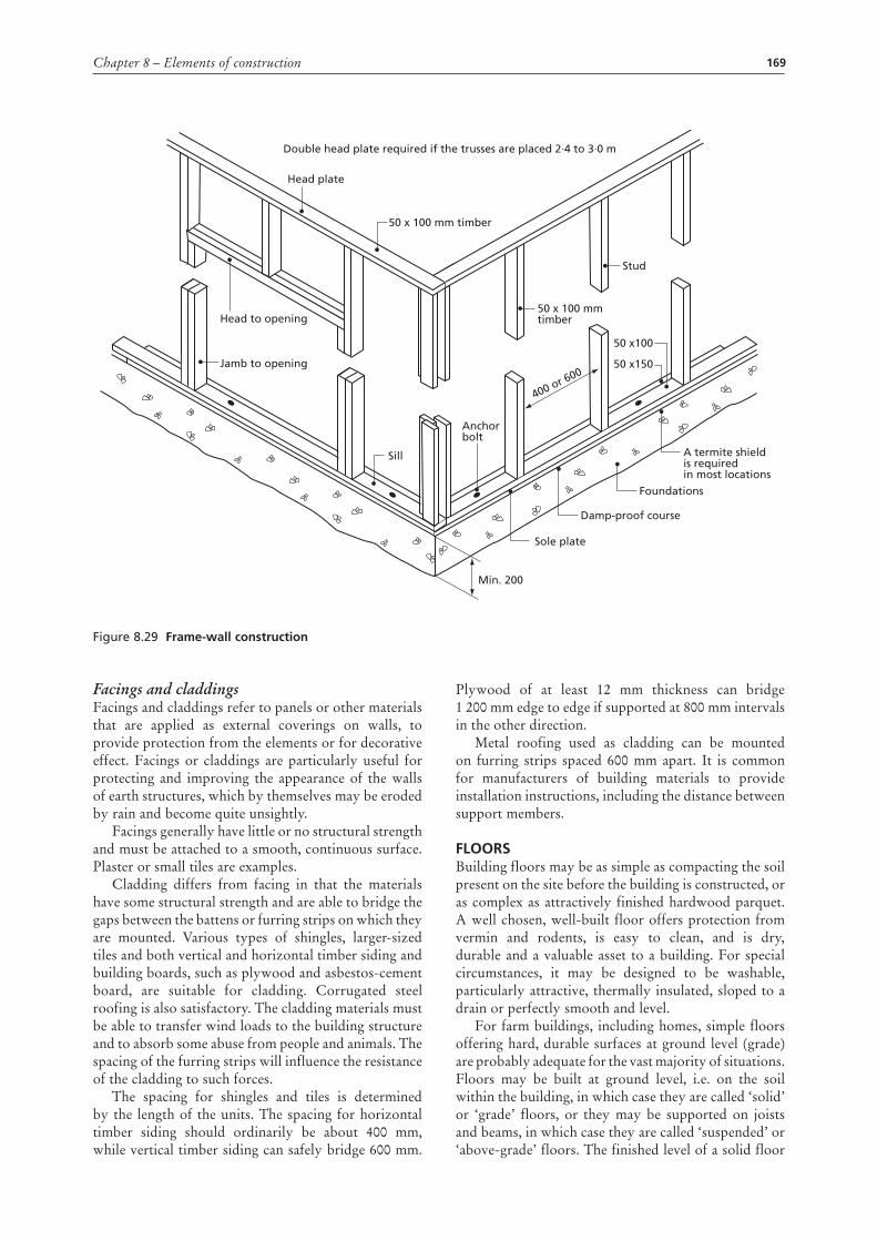
Frame wallsFrame walls consist of vertical timber members, called ‘studs’, framed between horizontal members at the top and bottom. The top member is called the ‘plate’ and the bottom member the ‘sole’ or ‘sill’. Simple butt joints are used, which are end-nailed or toe-nailed. As a result, the frame is not very rigid and requires bracing in order to provide adequate stiffness.
Figure 8.28 construction of a mud-and-pole wall
Although diagonal braces can be used for this purpose, a common method, which is quicker and cheaper, is to use building board or plywood sheathing to stiffen the structure. The studs are commonly spaced on 400 mm or 600 mm centres, which relates to the standard 1 200 mm width of many types of building boards used for sheathing. The load-bearing members of this type of wall are wood, so it is not recommended for use in termite areas, especially if both faces of the frame are finished or covered, making it difficult to detect a termite attack.
Frame construction using timber must be raised out of contact with ground moisture and protected from termites. This is accomplished by construction on a base wall or foundation beam rising to a damp-proof course, or on the edge of a concrete slab floor. As a base for the whole structure, a sill is set and carefully levelled on the damp-proof course, before being securely anchored to the foundation. To maintain the effectiveness of the damp-proof course, it must be sealed carefully at all bolt positions.
A continuous termite shield should be installed between the damp-proof course and the sill, and great care taken to seal around the holes required for the anchor bolts. The sill-plate may be 100 mm by 50 mm when fixed to a concrete base, but should be increased in width to 150 mm on a brick base wall.
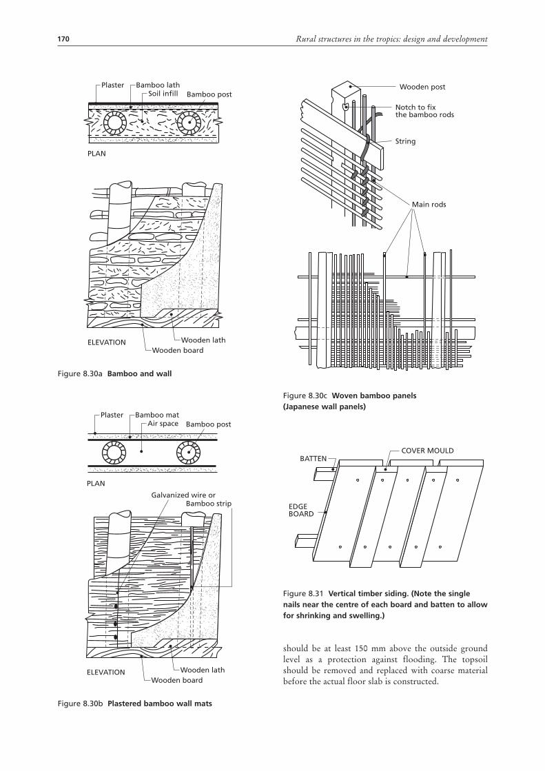
Instead of timber, bamboo or round wooden poles can be used as studs and then clad with bamboo mats, reed mats, grass, palm leaves, etc. An alternative is to fix mats to the studs and then plaster the mats with cement plaster or other material. Some structures of this type have a short life owing to damage by fungi and termites. They are also difficult to keep clean and pose a serious fire risk. Figure 8.30 gives brief information on bamboo wall panels that can be made by skilled craftsmen.
Figure 8.27 construction of a rammed-earth wall with a gliding form
Foundation wall
30−40 Ø BAMBOO REINFORCEMENT
Inside
PLAN
800800
800
100
169Chapter 8 – Elements of construction
Facings and claddingsFacings and claddings refer to panels or other materials that are applied as external coverings on walls, to provide protection from the elements or for decorative effect. Facings or claddings are particularly useful for protecting and improving the appearance of the walls of earth structures, which by themselves may be eroded by rain and become quite unsightly.
Facings generally have little or no structural strength and must be attached to a smooth, continuous surface. Plaster or small tiles are examples.
Cladding differs from facing in that the materials have some structural strength and are able to bridge the gaps between the battens or furring strips on which they are mounted. Various types of shingles, larger-sized tiles and both vertical and horizontal timber siding and building boards, such as plywood and asbestos-cement board, are suitable for cladding. Corrugated steel roofing is also satisfactory. The cladding materials must be able to transfer wind loads to the building structure and to absorb some abuse from people and animals. The spacing of the furring strips will influence the resistance of the cladding to such forces.
The spacing for shingles and tiles is determined by the length of the units. The spacing for horizontal timber siding should ordinarily be about 400 mm, while vertical timber siding can safely bridge 600 mm.
Plywood of at least 12 mm thickness can bridge 1 200 mm edge to edge if supported at 800 mm intervals in the other direction.
Metal roofing used as cladding can be mounted on furring strips spaced 600 mm apart. It is common for manufacturers of building materials to provide installation instructions, including the distance between support members.
FLoorsBuilding floors may be as simple as compacting the soil present on the site before the building is constructed, or as complex as attractively finished hardwood parquet. A well chosen, well-built floor offers protection from vermin and rodents, is easy to clean, and is dry, durable and a valuable asset to a building. For special circumstances, it may be designed to be washable, particularly attractive, thermally insulated, sloped to a drain or perfectly smooth and level.
For farm buildings, including homes, simple floors offering hard, durable surfaces at ground level (grade) are probably adequate for the vast majority of situations. Floors may be built at ground level, i.e. on the soil within the building, in which case they are called ‘solid’ or ‘grade’ floors, or they may be supported on joists and beams, in which case they are called ‘suspended’ or ‘above-grade’ floors. The finished level of a solid floor
Figure 8.29 Frame-wall construction
Double head plate required if the trusses are placed 2·4 to 3·0 m
Sill
Anchorbolt
Sole plate
Min. 200
Head to opening
Head plate
Jamb to opening
50 x 100 mm timber
50 x 100 mm timber
400 or 600
Stud
50 x150
50 x100
Damp-proof course
Foundations
A termite shield is requiredin most locations
170 Rural structures in the tropics: design and development
should be at least 150 mm above the outside ground level as a protection against flooding. The topsoil should be removed and replaced with coarse material before the actual floor slab is constructed.
Figure 8.30a bamboo and wall
Figure 8.30b plastered bamboo wall mats
Plaster Bamboo lath
Wooden board
Bamboo postSoil infill
ELEVATION
PLAN
Wooden lath
Plaster Bamboo mat
Wooden board
Galvanized wire or
Bamboo post
Bamboo strip
Air space
ELEVATION
PLAN
Wooden lath
Figure 8.30c Woven bamboo panels(Japanese wall panels)
Figure 8.31 Vertical timber siding. (note the single nails near the centre of each board and batten to allow for shrinking and swelling.)
Wooden post
Notch to fixthe bamboo rods
String
Main rods
COVER MOULD
EDGEBOARD
BATTEN
171Chapter 8 – Elements of construction
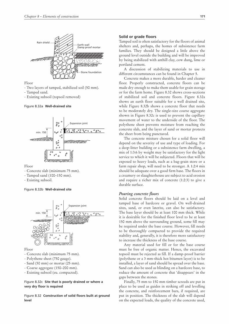
Floor- Two layers of tamped, stabilized soil (50 mm).- Tamped sand.- Existing subsoil (topsoil removed)
Figure 8.32a Well-drained site
Floor- Concrete slab (minimum 75 mm).- Tamped sand (100–150 mm).- Existing subsoil.
Figure 8.32b Well-drained site
Floor- Concrete slab (minimum 75 mm).- Polythene sheet (750 gauge).- Sand (50 mm) or mortar (25 mm).- Coarse aggregate (150–200 mm).- Existing subsoil (eu. compacted).
Figure 8.32c site that is poorly drained or where a very dry floor is required
Figure 8.32 construction of solid floors built at ground level
Rain shieldEarth wallDamp proof mortar
Stone foundation
Expansion joint
min. 150
Expansion joint
min. 150
solid or grade floorsTamped soil is often satisfactory for the floors of animal shelters and, perhaps, the homes of subsistence farm families. They should be designed a little above the ground level outside the building and will be improved by being stabilized with anthill clay, cow dung, lime or portland cement.
A discussion of stabilizing materials to use in different circumstances can be found in Chapter 5.
Concrete makes a more durable, harder and cleaner floor. Properly constructed, concrete floors can be made dry enough to make them usable for grain storage or for the farm home. Figure 8.32 shows cross-sections of stabilized soil and concrete floors. Figure 8.32a shows an earth floor suitable for a well drained site, while Figure 8.32b shows a concrete floor that needs to be moderately dry. The single-size coarse aggregate shown in Figure 8.32c is used to prevent the capillary movement of water to the underside of the floor. The polythene sheet prevents moisture from reaching the concrete slab, and the layer of sand or mortar protects the sheet from being punctured.
The concrete mixture chosen for a solid floor will depend on the severity of use and type of loading. For a deep-litter building or a subsistence farm dwelling, a mix of 1:3:6 by weight may be satisfactory for the light service to which it will be subjected. Floors that will be exposed to heavy loads, such as a bag-grain store or a farm repair shop, will need to be stronger. A 1:2:4 mix should be adequate over a good firm base. The floors in a creamery or slaughterhouse are subject to acid erosion and require a richer mix of concrete (1:2:3) to give a durable surface.
Pouring concrete floorsSolid concrete floors should be laid on a level and tamped base of hardcore or gravel. On well-drained sites, sand, or even laterite, can also be satisfactory. The base layer should be at least 100 mm thick. While it is desirable for the finished floor level to be at least 150 mm above the surrounding ground, some fill may be required under the base course. However, fill needs to be thoroughly compacted to provide the required stability and, generally, it is therefore more satisfactory to increase the thickness of the base course.
Any material used for fill or for the base course must be free of organic matter. Hence, the excavated topsoil must be rejected as fill. If a damp-proof barrier (polythene or a 3 mm-thick hot bitumen layer) is to be installed, a layer of sand should be spread over the base. Sand can also be used as blinding on a hardcore base, to reduce the amount of concrete that ‘disappears’ in the gaps between the stones.
Finally, 75 mm to 150 mm timber screeds are put in place to be used as guides in striking off and levelling the concrete, and reinforcement bars, if required, are put in position. The thickness of the slab will depend on the expected loads, the quality of the concrete used,
172 Rural structures in the tropics: design and development
the reinforcement and the bearing characteristics of the ground.
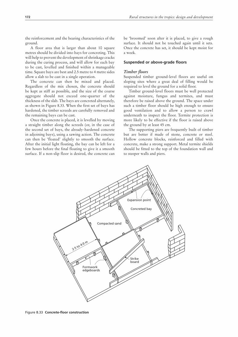
A floor area that is larger than about 10 square metres should be divided into bays for concreting. This will help to prevent the development of shrinkage cracks during the curing process, and will allow for each bay to be cast, levelled and finished within a manageable time. Square bays are best and 2.5 metre to 4 metre sides allow a slab to be cast in a single operation.
The concrete can then be mixed and placed. Regardless of the mix chosen, the concrete should be kept as stiff as possible, and the size of the coarse aggregate should not exceed one-quarter of the thickness of the slab. The bays are concreted alternately, as shown in Figure 8.33. When the first set of bays has hardened, the timber screeds are carefully removed and the remaining bays can be cast.
Once the concrete is placed, it is levelled by moving a straight timber along the screeds (or, in the case of the second set of bays, the already-hardened concrete in adjoining bays), using a sawing action. The concrete can then be ‘floated’ slightly to smooth the surface. After the initial light floating, the bay can be left for a few hours before the final floating to give it a smooth surface. If a non-slip floor is desired, the concrete can
be ‘broomed’ soon after it is placed, to give a rough surface. It should not be touched again until it sets. Once the concrete has set, it should be kept moist for a week.
suspended or above-grade floors
Timber floorsSuspended timber ground-level floors are useful on sloping sites where a great deal of filling would be required to level the ground for a solid floor.
Timber ground-level floors must be well protected against moisture, fungus and termites, and must therefore be raised above the ground. The space under such a timber floor should be high enough to ensure good ventilation and to allow a person to crawl underneath to inspect the floor. Termite protection is more likely to be effective if the floor is raised above the ground by at least 45 cm.
The supporting piers are frequently built of timber but are better if made of stone, concrete or steel. Hollow concrete blocks, reinforced and filled with concrete, make a strong support. Metal termite shields should be fitted to the top of the foundation wall and to steeper walls and piers.
Figure 8.33 concrete-floor construction
Expansion point
Concreted bay
Compacted sand
Formworkedgeboards
2∙5 to 4∙0 m
Strikeboard
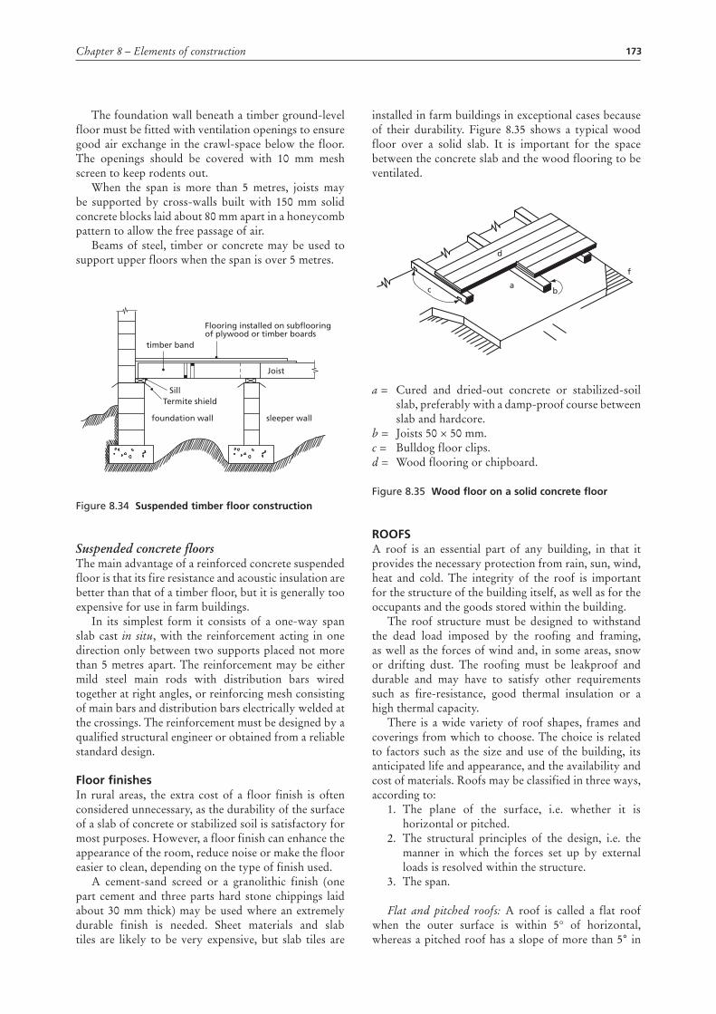
173Chapter 8 – Elements of construction
The foundation wall beneath a timber ground-level floor must be fitted with ventilation openings to ensure good air exchange in the crawl-space below the floor. The openings should be covered with 10 mm mesh screen to keep rodents out.
When the span is more than 5 metres, joists may be supported by cross-walls built with 150 mm solid concrete blocks laid about 80 mm apart in a honeycomb pattern to allow the free passage of air.
Beams of steel, timber or concrete may be used to support upper floors when the span is over 5 metres.
Figure 8.34 suspended timber floor construction
Suspended concrete floorsThe main advantage of a reinforced concrete suspended floor is that its fire resistance and acoustic insulation are better than that of a timber floor, but it is generally too expensive for use in farm buildings.
In its simplest form it consists of a one-way span slab cast in situ, with the reinforcement acting in one direction only between two supports placed not more than 5 metres apart. The reinforcement may be either mild steel main rods with distribution bars wired together at right angles, or reinforcing mesh consisting of main bars and distribution bars electrically welded at the crossings. The reinforcement must be designed by a qualified structural engineer or obtained from a reliable standard design.
Floor finishesIn rural areas, the extra cost of a floor finish is often considered unnecessary, as the durability of the surface of a slab of concrete or stabilized soil is satisfactory for most purposes. However, a floor finish can enhance the appearance of the room, reduce noise or make the floor easier to clean, depending on the type of finish used.
A cement-sand screed or a granolithic finish (one part cement and three parts hard stone chippings laid about 30 mm thick) may be used where an extremely durable finish is needed. Sheet materials and slab tiles are likely to be very expensive, but slab tiles are
SillTermite shield
foundation wall
Flooring installed on subflooring of plywood or timber boards
sleeper wall
Joist
timber band
installed in farm buildings in exceptional cases because of their durability. Figure 8.35 shows a typical wood floor over a solid slab. It is important for the space between the concrete slab and the wood flooring to be ventilated.
a = Cured and dried-out concrete or stabilized-soil slab, preferably with a damp-proof course between slab and hardcore. b = Joists 50 × 50 mm. c = Bulldog floor clips. d = Wood flooring or chipboard.
Figure 8.35 Wood floor on a solid concrete floor
rooFsA roof is an essential part of any building, in that it provides the necessary protection from rain, sun, wind, heat and cold. The integrity of the roof is important for the structure of the building itself, as well as for the occupants and the goods stored within the building.
The roof structure must be designed to withstand the dead load imposed by the roofing and framing, as well as the forces of wind and, in some areas, snow or drifting dust. The roofing must be leakproof and durable and may have to satisfy other requirements such as fire-resistance, good thermal insulation or a high thermal capacity.
There is a wide variety of roof shapes, frames and coverings from which to choose. The choice is related to factors such as the size and use of the building, its anticipated life and appearance, and the availability and cost of materials. Roofs may be classified in three ways, according to:
1. The plane of the surface, i.e. whether it is horizontal or pitched.
2. The structural principles of the design, i.e. the manner in which the forces set up by external loads is resolved within the structure.
3. The span.
Flat and pitched roofs: A roof is called a flat roof when the outer surface is within 5° of horizontal, whereas a pitched roof has a slope of more than 5° in
ac
d
f
b
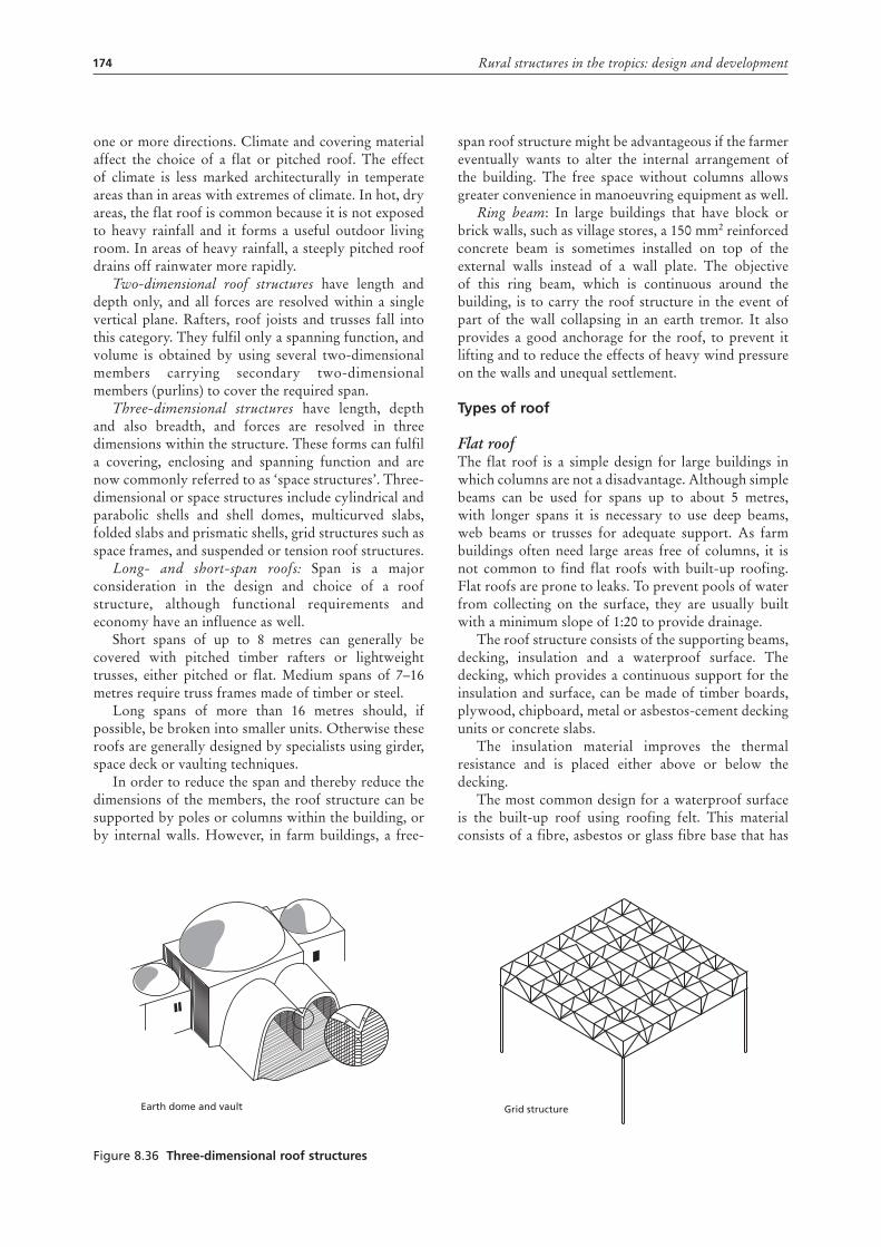
174 Rural structures in the tropics: design and development
one or more directions. Climate and covering material affect the choice of a flat or pitched roof. The effect of climate is less marked architecturally in temperate areas than in areas with extremes of climate. In hot, dry areas, the flat roof is common because it is not exposed to heavy rainfall and it forms a useful outdoor living room. In areas of heavy rainfall, a steeply pitched roof drains off rainwater more rapidly.
Two-dimensional roof structures have length and depth only, and all forces are resolved within a single vertical plane. Rafters, roof joists and trusses fall into this category. They fulfil only a spanning function, and volume is obtained by using several two-dimensional members carrying secondary two-dimensional members (purlins) to cover the required span.
Three-dimensional structures have length, depth and also breadth, and forces are resolved in three dimensions within the structure. These forms can fulfil a covering, enclosing and spanning function and are now commonly referred to as ‘space structures’. Three-dimensional or space structures include cylindrical and parabolic shells and shell domes, multicurved slabs, folded slabs and prismatic shells, grid structures such as space frames, and suspended or tension roof structures.
Long- and short-span roofs: Span is a major consideration in the design and choice of a roof structure, although functional requirements and economy have an influence as well.
Short spans of up to 8 metres can generally be covered with pitched timber rafters or lightweight trusses, either pitched or flat. Medium spans of 7–16 metres require truss frames made of timber or steel.
Long spans of more than 16 metres should, if possible, be broken into smaller units. Otherwise these roofs are generally designed by specialists using girder, space deck or vaulting techniques.
In order to reduce the span and thereby reduce the dimensions of the members, the roof structure can be supported by poles or columns within the building, or by internal walls. However, in farm buildings, a free-
span roof structure might be advantageous if the farmer eventually wants to alter the internal arrangement of the building. The free space without columns allows greater convenience in manoeuvring equipment as well.
Ring beam: In large buildings that have block or brick walls, such as village stores, a 150 mm2 reinforced concrete beam is sometimes installed on top of the external walls instead of a wall plate. The objective of this ring beam, which is continuous around the building, is to carry the roof structure in the event of part of the wall collapsing in an earth tremor. It also provides a good anchorage for the roof, to prevent it lifting and to reduce the effects of heavy wind pressure on the walls and unequal settlement.
types of roof
Flat roofThe flat roof is a simple design for large buildings in which columns are not a disadvantage. Although simple beams can be used for spans up to about 5 metres, with longer spans it is necessary to use deep beams, web beams or trusses for adequate support. As farm buildings often need large areas free of columns, it is not common to find flat roofs with built-up roofing. Flat roofs are prone to leaks. To prevent pools of water from collecting on the surface, they are usually built with a minimum slope of 1:20 to provide drainage.
The roof structure consists of the supporting beams, decking, insulation and a waterproof surface. The decking, which provides a continuous support for the insulation and surface, can be made of timber boards, plywood, chipboard, metal or asbestos-cement decking units or concrete slabs.
The insulation material improves the thermal resistance and is placed either above or below the decking.
The most common design for a waterproof surface is the built-up roof using roofing felt. This material consists of a fibre, asbestos or glass fibre base that has
Figure 8.36 three-dimensional roof structures
Earth dome and vault Grid structure
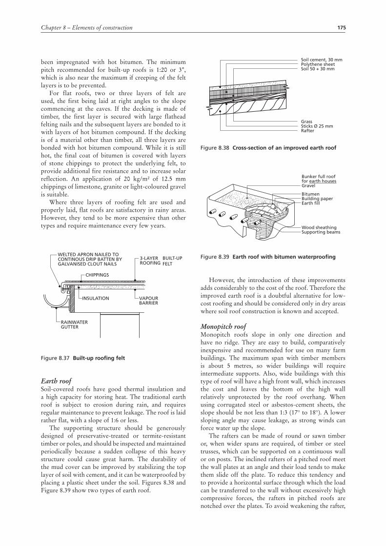
175Chapter 8 – Elements of construction
been impregnated with hot bitumen. The minimum pitch recommended for built-up roofs is 1:20 or 3°, which is also near the maximum if creeping of the felt layers is to be prevented.
For flat roofs, two or three layers of felt are used, the first being laid at right angles to the slope commencing at the eaves. If the decking is made of timber, the first layer is secured with large flathead felting nails and the subsequent layers are bonded to it with layers of hot bitumen compound. If the decking is of a material other than timber, all three layers are bonded with hot bitumen compound. While it is still hot, the final coat of bitumen is covered with layers of stone chippings to protect the underlying felt, to provide additional fire resistance and to increase solar reflection. An application of 20 kg/m² of 12.5 mm chippings of limestone, granite or light-coloured gravel is suitable.
Where three layers of roofing felt are used and properly laid, flat roofs are satisfactory in rainy areas. However, they tend to be more expensive than other types and require maintenance every few years.
Figure 8.37 built-up roofing felt
Earth roofSoil-covered roofs have good thermal insulation and a high capacity for storing heat. The traditional earth roof is subject to erosion during rain, and requires regular maintenance to prevent leakage. The roof is laid rather flat, with a slope of 1:6 or less.
The supporting structure should be generously designed of preservative-treated or termite-resistant timber or poles, and should be inspected and maintained periodically because a sudden collapse of this heavy structure could cause great harm. The durability of the mud cover can be improved by stabilizing the top layer of soil with cement, and it can be waterproofed by placing a plastic sheet under the soil. Figures 8.38 and Figure 8.39 show two types of earth roof.
CHIPPINGS
3-LAYER ROOFING
VAPOUR BARRIER
INSULATION
RAINWATERGUTTER
WELTED APRON NAILED TOCONTINOUS DRIP BATTEN BYGALVANISED CLOUT NAILS
BUILT-UP FELT
Figure 8.38 cross-section of an improved earth roof
Figure 8.39 Earth roof with bitumen waterproofing
However, the introduction of these improvements adds considerably to the cost of the roof. Therefore the improved earth roof is a doubtful alternative for low-cost roofing and should be considered only in dry areas where soil roof construction is known and accepted.
Monopitch roofMonopitch roofs slope in only one direction and have no ridge. They are easy to build, comparatively inexpensive and recommended for use on many farm buildings. The maximum span with timber members is about 5 metres, so wider buildings will require intermediate supports. Also, wide buildings with this type of roof will have a high front wall, which increases the cost and leaves the bottom of the high wall relatively unprotected by the roof overhang. When using corrugated steel or asbestos-cement sheets, the slope should be not less than 1:3 (17° to 18°). A lower sloping angle may cause leakage, as strong winds can force water up the slope.
The rafters can be made of round or sawn timber or, when wider spans are required, of timber or steel trusses, which can be supported on a continuous wall or on posts. The inclined rafters of a pitched roof meet the wall plates at an angle and their load tends to make them slide off the plate. To reduce this tendency and to provide a horizontal surface through which the load can be transferred to the wall without excessively high compressive forces, the rafters in pitched roofs are notched over the plates. To avoid weakening the rafter,
Soil cement, 30 mmPolythene sheetSoil 50 + 30 mm
GrassSticks Ø 25 mmRafter
Bunker full rooffor earth housesGravel
BitumenBuilding paperEarth fill
Wood sheathingSupporting beams
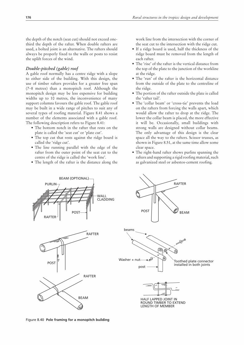
176 Rural structures in the tropics: design and development
the depth of the notch (seat cut) should not exceed one-third the depth of the rafter. When double rafters are used, a bolted joint is an alternative. The rafters should always be properly fixed to the walls or posts to resist the uplift forces of the wind.
Double-pitched (gable) roofA gable roof normally has a centre ridge with a slope to either side of the building. With this design, the use of timber rafters provides for a greater free span (7–8 metres) than a monopitch roof. Although the monopitch design may be less expensive for building widths up to 10 metres, the inconvenience of many support columns favours the gable roof. The gable roof may be built in a wide range of pitches to suit any of several types of roofing material. Figure 8.41 shows a number of the elements associated with a gable roof. The following description refers to Figure 8.41:
• The bottom notch in the rafter that rests on the plate is called the ‘seat cut’ or ‘plate cut’.
• The top cut that rests against the ridge board is called the ‘ridge cut’.
• The line running parallel with the edge of the rafter from the outer point of the seat cut to the centre of the ridge is called the ‘work line’.
• The length of the rafter is the distance along the
work line from the intersection with the corner of the seat cut to the intersection with the ridge cut.
• If a ridge board is used, half the thickness of the ridge board must be removed from the length of each rafter.
• The ‘rise’ of the rafter is the vertical distance from the top of the plate to the junction of the workline at the ridge.
• The ‘run’ of the rafter is the horizontal distance from the outside of the plate to the centreline of the ridge.
• The portion of the rafter outside the plate is called the ‘rafter tail’.
• The ‘collar beam’ or ‘cross-tie’ prevents the load on the rafters from forcing the walls apart, which would allow the rafter to drop at the ridge. The lower the collar beam is placed, the more effective it will be. Occasionally, small buildings with strong walls are designed without collar beams. The only advantage of this design is the clear space all the way to the rafters. Scissor trusses, as shown in Figure 8.51, at the same time allow some clear space.
• The right-hand rafter shows purlins spanning the rafters and supporting a rigid roofing material, such as galvanized steel or asbestos-cement roofing.
Figure 8.40 pole framing for a monopitch building
PURLIN
RAFTER
RAFTER
RAFTER
POST
POST
WALLCLADDING
BEAM (OPTIONAL)
BEAM HALF LAPPED JOINT INROUND TIMBER TO EXTENDLENGTH OF MEMBER
RAFTER
POST
post
Toothed plate connectorinstalled in both joints
BEAM
beams
Washer + nut
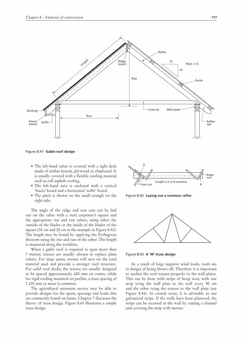
177Chapter 8 – Elements of construction
• The left-hand rafter is covered with a tight deck made of timber boards, plywood or chipboard. It is usually covered with a flexible roofing material such as roll asphalt roofing.
• The left-hand eave is enclosed with a vertical ‘fascia’ board and a horizontal ‘soffit’ board.
• The pitch is shown on the small triangle on the right side.
The angle of the ridge and seat cuts can be laid out on the rafter with a steel carpenter’s square and the appropriate rise and run values, using either the outside of the blades or the inside of the blades of the square (30 cm and 20 cm in the example in Figure 8.42). The length may be found by applying the Pythagoras theorem using the rise and run of the rafter. The length is measured along the workline.
When a gable roof is required to span more than 7 metres, trusses are usually chosen to replace plain rafters. For large spans, trusses will save on the total material used and provide a stronger roof structure. For solid roof decks, the trusses are usually designed to be spaced approximately 600 mm on centre, while for rigid roofing mounted on purlins, a truss spacing of 1 200 mm or more is common.
The agricultural extension service may be able to provide designs for the spans, spacings and loads that are commonly found on farms. Chapter 7 discusses the theory of truss design. Figure 8.43 illustrates a simple truss design.
Figure 8.42 Laying out a common rafter
Figure 8.43 a ‘W’-truss design
As a result of large negative wind loads, roofs are in danger of being blown off. Therefore it is important to anchor the roof trusses properly to the wall plates. This can be done with strips of hoop iron, with one strip tying the wall plate to the wall every 90 cm and the other tying the trusses to the wall plate (see Figure 8.44). In coastal areas, it is advisable to use galvanized strips. If the walls have been plastered, the strips can be recessed in the wall by cutting a channel and covering the strip with mortar.
Seat cutsLength is A to B workline
Ridge cuts
B
A
Figure 8.41 gable-roof design
15
10
Pitch 1:15
Rafter
Length Ridge
board
Run
SoffitFasciaboard
Decking
Purlin
Wall plateCross tie
Rise
Raftertail
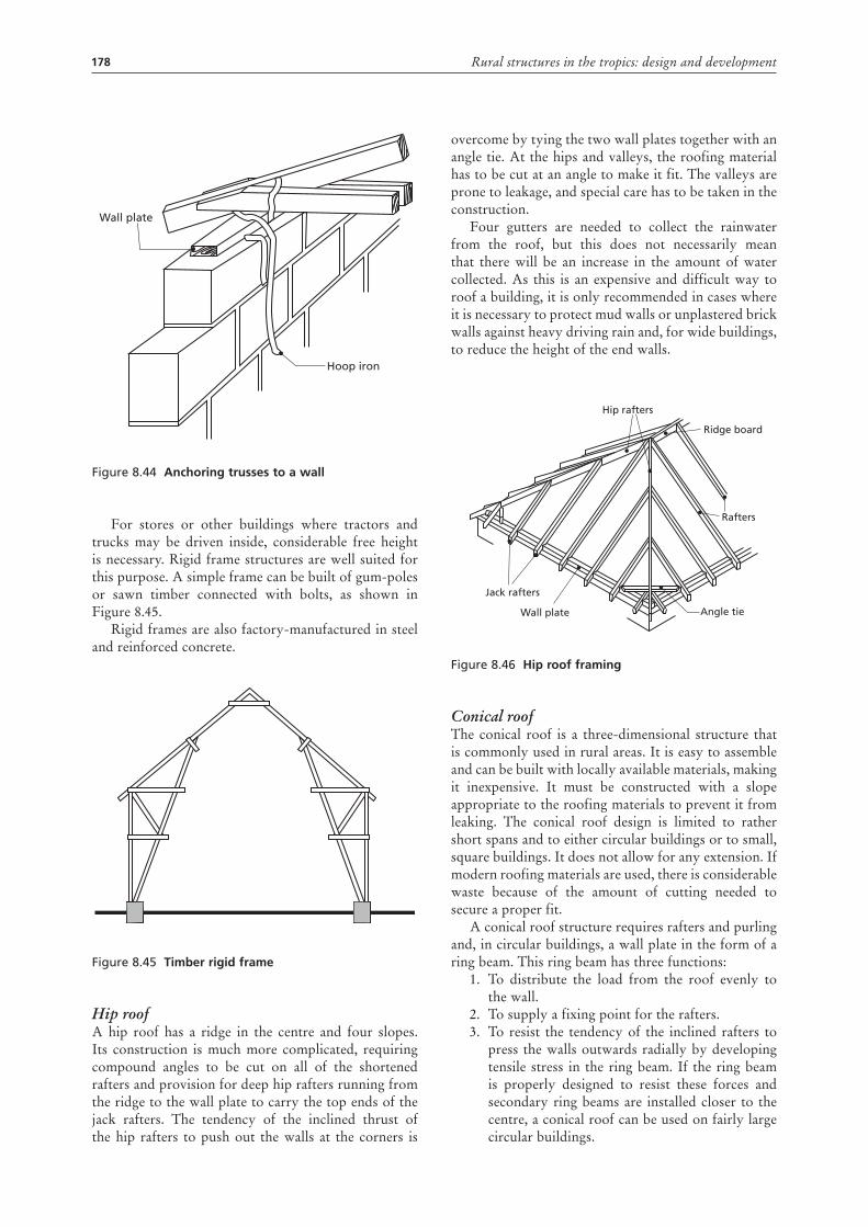
178 Rural structures in the tropics: design and development
Figure 8.44 anchoring trusses to a wall
For stores or other buildings where tractors and trucks may be driven inside, considerable free height is necessary. Rigid frame structures are well suited for this purpose. A simple frame can be built of gum-poles or sawn timber connected with bolts, as shown in Figure 8.45.
Rigid frames are also factory-manufactured in steel and reinforced concrete.
Figure 8.45 timber rigid frame
Hip roofA hip roof has a ridge in the centre and four slopes. Its construction is much more complicated, requiring compound angles to be cut on all of the shortened rafters and provision for deep hip rafters running from the ridge to the wall plate to carry the top ends of the jack rafters. The tendency of the inclined thrust of the hip rafters to push out the walls at the corners is
Wall plate
Hoop iron
overcome by tying the two wall plates together with an angle tie. At the hips and valleys, the roofing material has to be cut at an angle to make it fit. The valleys are prone to leakage, and special care has to be taken in the construction.
Four gutters are needed to collect the rainwater from the roof, but this does not necessarily mean that there will be an increase in the amount of water collected. As this is an expensive and difficult way to roof a building, it is only recommended in cases where it is necessary to protect mud walls or unplastered brick walls against heavy driving rain and, for wide buildings, to reduce the height of the end walls.
Figure 8.46 Hip roof framing
Conical roofThe conical roof is a three-dimensional structure that is commonly used in rural areas. It is easy to assemble and can be built with locally available materials, making it inexpensive. It must be constructed with a slope appropriate to the roofing materials to prevent it from leaking. The conical roof design is limited to rather short spans and to either circular buildings or to small, square buildings. It does not allow for any extension. If modern roofing materials are used, there is considerable waste because of the amount of cutting needed to secure a proper fit.
A conical roof structure requires rafters and purling and, in circular buildings, a wall plate in the form of a ring beam. This ring beam has three functions:
1. To distribute the load from the roof evenly to the wall.
2. To supply a fixing point for the rafters.3. To resist the tendency of the inclined rafters to
press the walls outwards radially by developing tensile stress in the ring beam. If the ring beam is properly designed to resist these forces and secondary ring beams are installed closer to the centre, a conical roof can be used on fairly large circular buildings.
Hip rafters
Ridge board
Jack rafters
Wall plate Angle tie
Rafters
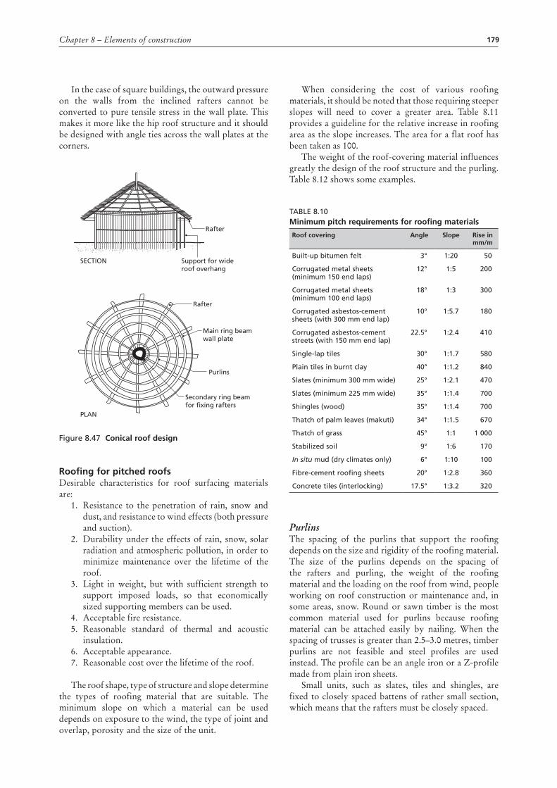
179Chapter 8 – Elements of construction
In the case of square buildings, the outward pressure on the walls from the inclined rafters cannot be converted to pure tensile stress in the wall plate. This makes it more like the hip roof structure and it should be designed with angle ties across the wall plates at the corners.
Figure 8.47 conical roof design
roofing for pitched roofsDesirable characteristics for roof surfacing materials are:
1. Resistance to the penetration of rain, snow and dust, and resistance to wind effects (both pressure and suction).
2. Durability under the effects of rain, snow, solar radiation and atmospheric pollution, in order to minimize maintenance over the lifetime of the roof.
3. Light in weight, but with sufficient strength to support imposed loads, so that economically sized supporting members can be used.
4. Acceptable fire resistance. 5. Reasonable standard of thermal and acoustic
insulation. 6. Acceptable appearance. 7. Reasonable cost over the lifetime of the roof.
The roof shape, type of structure and slope determine the types of roofing material that are suitable. The minimum slope on which a material can be used depends on exposure to the wind, the type of joint and overlap, porosity and the size of the unit.
Rafter
Rafter
Main ring beamwall plate
Purlins
Secondary ring beamfor fixing rafters
Support for wideroof overhang
SECTION
PLAN
When considering the cost of various roofing materials, it should be noted that those requiring steeper slopes will need to cover a greater area. Table 8.11 provides a guideline for the relative increase in roofing area as the slope increases. The area for a flat roof has been taken as 100.
The weight of the roof-covering material influences greatly the design of the roof structure and the purling. Table 8.12 shows some examples.
Table 8.10minimum pitch requirements for roofing materials
roof covering angle slope rise in mm/m
built-up bitumen felt 3° 1:20 50
Corrugated metal sheets (minimum 150 end laps)
12° 1:5 200
Corrugated metal sheets (minimum 100 end laps)
18° 1:3 300
Corrugated asbestos-cement sheets (with 300 mm end lap)
10° 1:5.7 180
Corrugated asbestos-cement streets (with 150 mm end lap)
22.5° 1:2.4 410
Single-lap tiles 30° 1:1.7 580
Plain tiles in burnt clay 40° 1:1.2 840
Slates (minimum 300 mm wide) 25° 1:2.1 470
Slates (minimum 225 mm wide) 35° 1:1.4 700
Shingles (wood) 35° 1:1.4 700
Thatch of palm leaves (makuti) 34° 1:1.5 670
Thatch of grass 45° 1:1 1 000
Stabilized soil 9° 1:6 170
In situ mud (dry climates only) 6° 1:10 100
Fibre-cement roofing sheets 20° 1:2.8 360
Concrete tiles (interlocking) 17.5° 1:3.2 320
PurlinsThe spacing of the purlins that support the roofing depends on the size and rigidity of the roofing material. The size of the purlins depends on the spacing of the rafters and purling, the weight of the roofing material and the loading on the roof from wind, people working on roof construction or maintenance and, in some areas, snow. Round or sawn timber is the most common material used for purlins because roofing material can be attached easily by nailing. When the spacing of trusses is greater than 2.5–3.0 metres, timber purlins are not feasible and steel profiles are used instead. The profile can be an angle iron or a Z-profile made from plain iron sheets.
Small units, such as slates, tiles and shingles, are fixed to closely spaced battens of rather small section, which means that the rafters must be closely spaced.
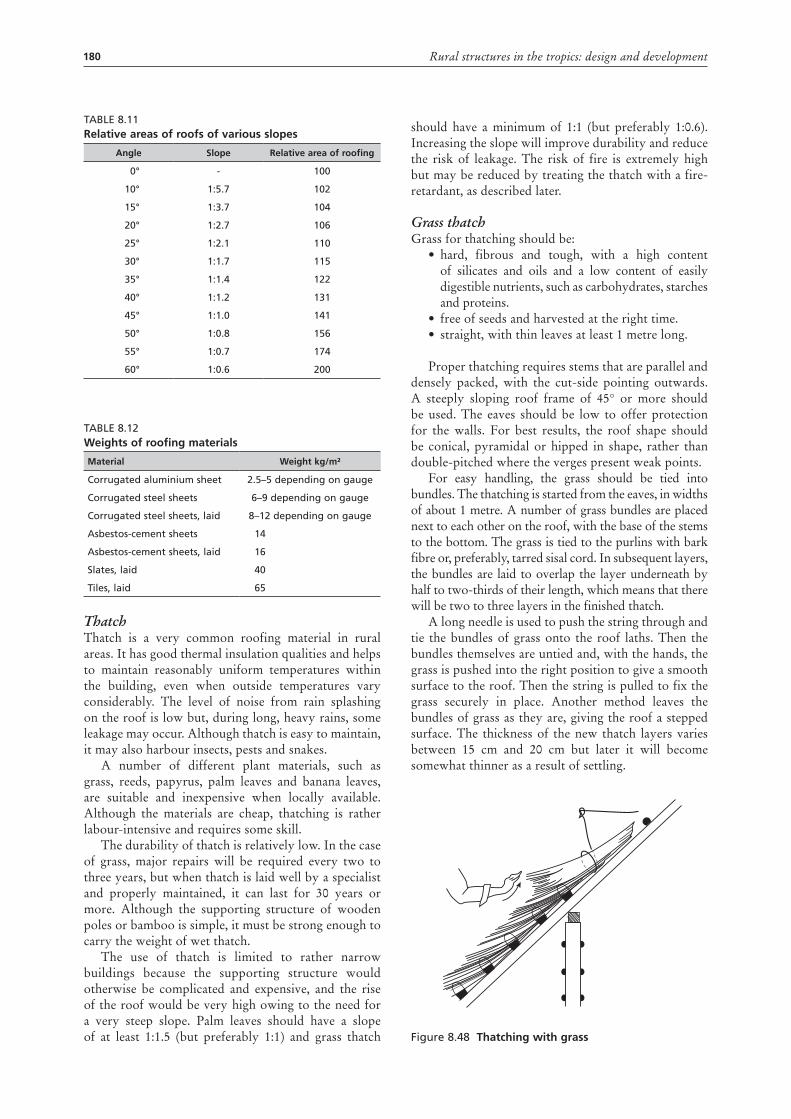
180 Rural structures in the tropics: design and development
Table 8.11relative areas of roofs of various slopes
angle slope relative area of roofing
0° - 100
10° 1:5.7 102
15° 1:3.7 104
20° 1:2.7 106
25° 1:2.1 110
30° 1:1.7 115
35° 1:1.4 122
40° 1:1.2 131
45° 1:1.0 141
50° 1:0.8 156
55° 1:0.7 174
60° 1:0.6 200
Table 8.12Weights of roofing materials
material Weight kg/m²
Corrugated aluminium sheet 2.5–5 depending on gauge
Corrugated steel sheets 6–9 depending on gauge
Corrugated steel sheets, laid 8–12 depending on gauge
asbestos-cement sheets 14
asbestos-cement sheets, laid 16
Slates, laid 40
Tiles, laid 65
ThatchThatch is a very common roofing material in rural areas. It has good thermal insulation qualities and helps to maintain reasonably uniform temperatures within the building, even when outside temperatures vary considerably. The level of noise from rain splashing on the roof is low but, during long, heavy rains, some leakage may occur. Although thatch is easy to maintain, it may also harbour insects, pests and snakes.
A number of different plant materials, such as grass, reeds, papyrus, palm leaves and banana leaves, are suitable and inexpensive when locally available. Although the materials are cheap, thatching is rather labour-intensive and requires some skill.
The durability of thatch is relatively low. In the case of grass, major repairs will be required every two to three years, but when thatch is laid well by a specialist and properly maintained, it can last for 30 years or more. Although the supporting structure of wooden poles or bamboo is simple, it must be strong enough to carry the weight of wet thatch.
The use of thatch is limited to rather narrow buildings because the supporting structure would otherwise be complicated and expensive, and the rise of the roof would be very high owing to the need for a very steep slope. Palm leaves should have a slope of at least 1:1.5 (but preferably 1:1) and grass thatch
should have a minimum of 1:1 (but preferably 1:0.6). Increasing the slope will improve durability and reduce the risk of leakage. The risk of fire is extremely high but may be reduced by treating the thatch with a fire-retardant, as described later.
Grass thatch Grass for thatching should be:
• hard, fibrous and tough, with a high content of silicates and oils and a low content of easily digestible nutrients, such as carbohydrates, starches and proteins.
• free of seeds and harvested at the right time. • straight, with thin leaves at least 1 metre long.
Proper thatching requires stems that are parallel and densely packed, with the cut-side pointing outwards. A steeply sloping roof frame of 45° or more should be used. The eaves should be low to offer protection for the walls. For best results, the roof shape should be conical, pyramidal or hipped in shape, rather than double-pitched where the verges present weak points.
For easy handling, the grass should be tied into bundles. The thatching is started from the eaves, in widths of about 1 metre. A number of grass bundles are placed next to each other on the roof, with the base of the stems to the bottom. The grass is tied to the purlins with bark fibre or, preferably, tarred sisal cord. In subsequent layers, the bundles are laid to overlap the layer underneath by half to two-thirds of their length, which means that there will be two to three layers in the finished thatch.
A long needle is used to push the string through and tie the bundles of grass onto the roof laths. Then the bundles themselves are untied and, with the hands, the grass is pushed into the right position to give a smooth surface to the roof. Then the string is pulled to fix the grass securely in place. Another method leaves the bundles of grass as they are, giving the roof a stepped surface. The thickness of the new thatch layers varies between 15 cm and 20 cm but later it will become somewhat thinner as a result of settling.
Figure 8.48 thatching with grass
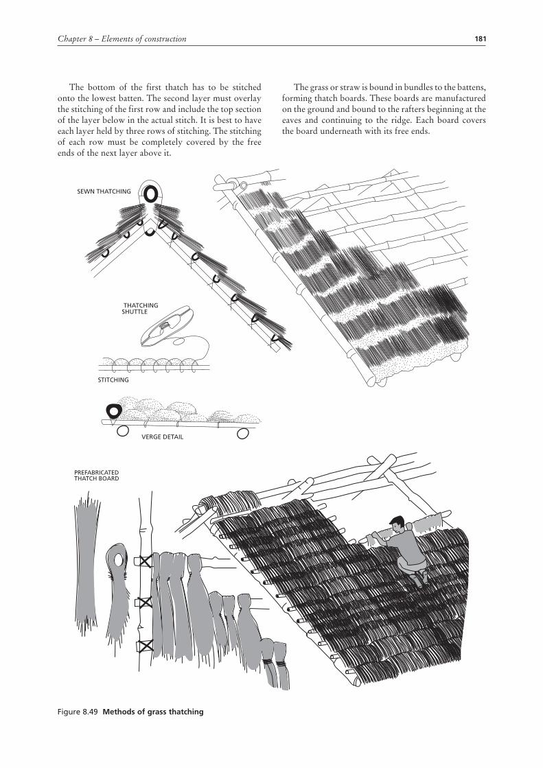
181Chapter 8 – Elements of construction
The bottom of the first thatch has to be stitched onto the lowest batten. The second layer must overlay the stitching of the first row and include the top section of the layer below in the actual stitch. It is best to have each layer held by three rows of stitching. The stitching of each row must be completely covered by the free ends of the next layer above it.
The grass or straw is bound in bundles to the battens, forming thatch boards. These boards are manufactured on the ground and bound to the rafters beginning at the eaves and continuing to the ridge. Each board covers the board underneath with its free ends.
Figure 8.49 methods of grass thatching
PREFABRICATEDTHATCH BOARD
SEWN THATCHING
THATCHINGSHUTTLE
STITCHING
VERGE DETAIL
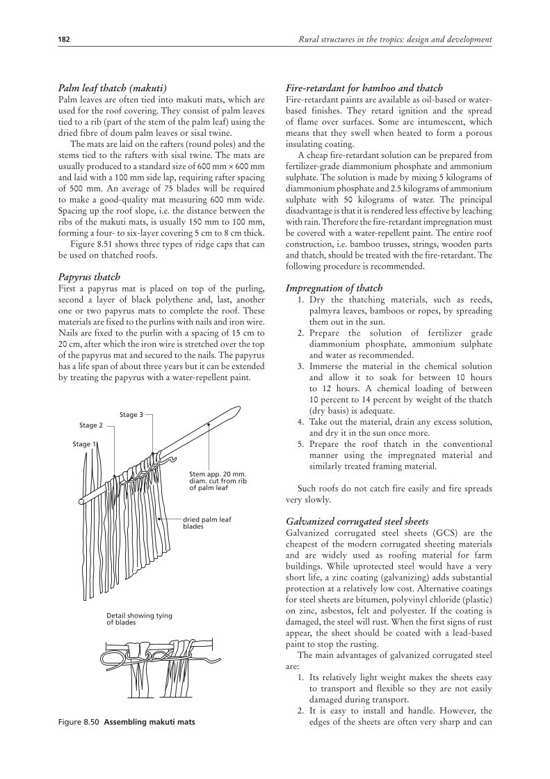
182 Rural structures in the tropics: design and development
Palm leaf thatch (makuti)Palm leaves are often tied into makuti mats, which are used for the roof covering. They consist of palm leaves tied to a rib (part of the stem of the palm leaf) using the dried fibre of doum palm leaves or sisal twine.
The mats are laid on the rafters (round poles) and the stems tied to the rafters with sisal twine. The mats are usually produced to a standard size of 600 mm × 600 mm and laid with a 100 mm side lap, requiring rafter spacing of 500 mm. An average of 75 blades will be required to make a good-quality mat measuring 600 mm wide. Spacing up the roof slope, i.e. the distance between the ribs of the makuti mats, is usually 150 mm to 100 mm, forming a four- to six-layer covering 5 cm to 8 cm thick.
Figure 8.51 shows three types of ridge caps that can be used on thatched roofs.
Papyrus thatchFirst a papyrus mat is placed on top of the purling, second a layer of black polythene and, last, another one or two papyrus mats to complete the roof. These materials are fixed to the purlins with nails and iron wire. Nails are fixed to the purlin with a spacing of 15 cm to 20 cm, after which the iron wire is stretched over the top of the papyrus mat and secured to the nails. The papyrus has a life span of about three years but it can be extended by treating the papyrus with a water-repellent paint.
Figure 8.50 assembling makuti mats
Stage 1
Stage 2
Stage 3
Stem app. 20 mm.diam. cut from ribof palm leaf
dried palm leafblades
Detail showing tyingof blades
Fire-retardant for bamboo and thatchFire-retardant paints are available as oil-based or water-based finishes. They retard ignition and the spread of flame over surfaces. Some are intumescent, which means that they swell when heated to form a porous insulating coating.
A cheap fire-retardant solution can be prepared from fertilizer-grade diammonium phosphate and ammonium sulphate. The solution is made by mixing 5 kilograms of diammonium phosphate and 2.5 kilograms of ammonium sulphate with 50 kilograms of water. The principal disadvantage is that it is rendered less effective by leaching with rain. Therefore the fire-retardant impregnation must be covered with a water-repellent paint. The entire roof construction, i.e. bamboo trusses, strings, wooden parts and thatch, should be treated with the fire-retardant. The following procedure is recommended.
Impregnation of thatch1. Dry the thatching materials, such as reeds,
palmyra leaves, bamboos or ropes, by spreading them out in the sun.
2. Prepare the solution of fertilizer grade diammonium phosphate, ammonium sulphate and water as recommended.
3. Immerse the material in the chemical solution and allow it to soak for between 10 hours to 12 hours. A chemical loading of between 10 percent to 14 percent by weight of the thatch (dry basis) is adequate.
4. Take out the material, drain any excess solution, and dry it in the sun once more.
5. Prepare the roof thatch in the conventional manner using the impregnated material and similarly treated framing material.
Such roofs do not catch fire easily and fire spreads very slowly.
Galvanized corrugated steel sheetsGalvanized corrugated steel sheets (GCS) are the cheapest of the modern corrugated sheeting materials and are widely used as roofing material for farm buildings. While uprotected steel would have a very short life, a zinc coating (galvanizing) adds substantial protection at a relatively low cost. Alternative coatings for steel sheets are bitumen, polyvinyl chloride (plastic) on zinc, asbestos, felt and polyester. If the coating is damaged, the steel will rust. When the first signs of rust appear, the sheet should be coated with a lead-based paint to stop the rusting.
The main advantages of galvanized corrugated steel are:
1. Its relatively light weight makes the sheets easy to transport and flexible so they are not easily damaged during transport.
2. It is easy to install and handle. However, the edges of the sheets are often very sharp and can
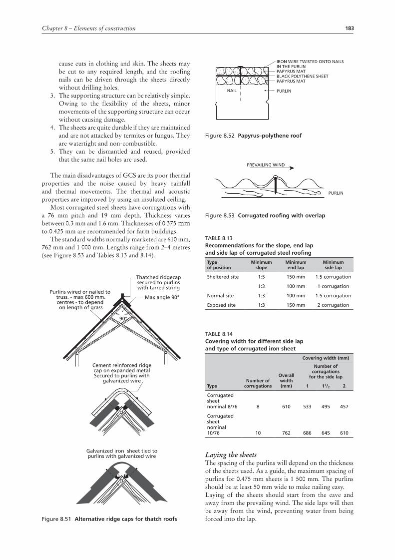
183Chapter 8 – Elements of construction
cause cuts in clothing and skin. The sheets may be cut to any required length, and the roofing nails can be driven through the sheets directly without drilling holes.
3. The supporting structure can be relatively simple. Owing to the flexibility of the sheets, minor movements of the supporting structure can occur without causing damage.
4. The sheets are quite durable if they are maintained and are not attacked by termites or fungus. They are watertight and non-combustible.
5. They can be dismantled and reused, provided that the same nail holes are used.
The main disadvantages of GCS are its poor thermal properties and the noise caused by heavy rainfall and thermal movements. The thermal and acoustic properties are improved by using an insulated ceiling.
Most corrugated steel sheets have corrugations with a 76 mm pitch and 19 mm depth. Thickness varies between 0.3 mm and 1.6 mm. Thicknesses of 0.375 mm to 0.425 mm are recommended for farm buildings.
The standard widths normally marketed are 610 mm, 762 mm and 1 000 mm. Lengths range from 2–4 metres (see Figure 8.53 and Tables 8.13 and 8.14).
Figure 8.51 alternative ridge caps for thatch roofs
Cement reinforced ridgecap on expanded metalSecured to purlins with
galvanized wire
Thatched ridgecapsecured to purlinswith tarred string
Purlins wired or nailed to truss. - max 600 mm.centres - to depend on length of grass
Max angle 90°
90°
Galvanized iron sheet tied topurlins with galvanized wire
Figure 8.52 papyrus–polythene roof
Figure 8.53 corrugated roofing with overlap
Table 8.13recommendations for the slope, end lap and side lap of corrugated steel roofing
type of position
minimum slope
minimum end lap
minimum side lap
Sheltered site 1:5 150 mm 1.5 corrugation
1:3 100 mm 1 corrugation
Normal site 1:3 100 mm 1.5 corrugation
exposed site 1:3 150 mm 2 corrugation
Table 8.14covering width for different side lap and type of corrugated iron sheet
typenumber of
corrugations
overall width (mm)
covering width (mm)
number of corrugations
for the side lap
1 11/2 2
Corrugated sheet nominal 8/76 8 610 533 495 457
Corrugated sheet nominal 10/76 10 762 686 645 610
Laying the sheetsThe spacing of the purlins will depend on the thickness of the sheets used. As a guide, the maximum spacing of purlins for 0.475 mm sheets is 1 500 mm. The purlins should be at least 50 mm wide to make nailing easy.Laying of the sheets should start from the eave and away from the prevailing wind. The side laps will then be away from the wind, preventing water from being forced into the lap.
IRON WIRE TWISTED ONTO NAILSIN THE PURLINPAPYRUS MATBLACK POLYTHENE SHEETPAPYRUS MAT
PURLINNAIL
PREVAILING WIND
PURLIN
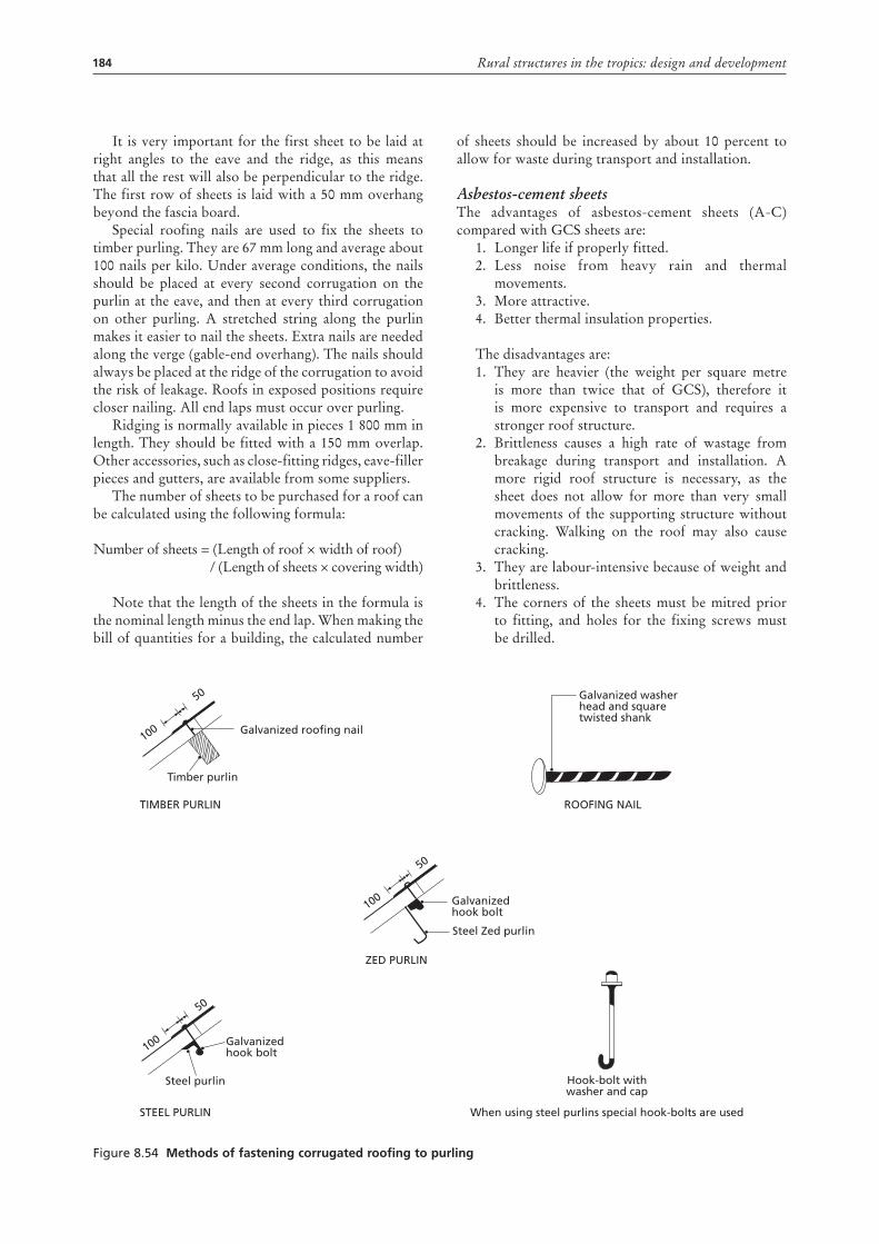
184 Rural structures in the tropics: design and development
It is very important for the first sheet to be laid at right angles to the eave and the ridge, as this means that all the rest will also be perpendicular to the ridge. The first row of sheets is laid with a 50 mm overhang beyond the fascia board.
Special roofing nails are used to fix the sheets to timber purling. They are 67 mm long and average about 100 nails per kilo. Under average conditions, the nails should be placed at every second corrugation on the purlin at the eave, and then at every third corrugation on other purling. A stretched string along the purlin makes it easier to nail the sheets. Extra nails are needed along the verge (gable-end overhang). The nails should always be placed at the ridge of the corrugation to avoid the risk of leakage. Roofs in exposed positions require closer nailing. All end laps must occur over purling.
Ridging is normally available in pieces 1 800 mm in length. They should be fitted with a 150 mm overlap. Other accessories, such as close-fitting ridges, eave-filler pieces and gutters, are available from some suppliers.
The number of sheets to be purchased for a roof can be calculated using the following formula:
Number of sheets = (Length of roof × width of roof) / (Length of sheets × covering width)
Note that the length of the sheets in the formula is the nominal length minus the end lap. When making the bill of quantities for a building, the calculated number
of sheets should be increased by about 10 percent to allow for waste during transport and installation.
Asbestos-cement sheetsThe advantages of asbestos-cement sheets (A-C) compared with GCS sheets are:
1. Longer life if properly fitted. 2. Less noise from heavy rain and thermal
movements.3. More attractive. 4. Better thermal insulation properties.
The disadvantages are:1. They are heavier (the weight per square metre
is more than twice that of GCS), therefore it is more expensive to transport and requires a stronger roof structure.
2. Brittleness causes a high rate of wastage from breakage during transport and installation. A more rigid roof structure is necessary, as the sheet does not allow for more than very small movements of the supporting structure without cracking. Walking on the roof may also cause cracking.
3. They are labour-intensive because of weight and brittleness.
4. The corners of the sheets must be mitred prior to fitting, and holes for the fixing screws must be drilled.
Figure 8.54 methods of fastening corrugated roofing to purling
Galvanized roofing nail
Timber purlin
TIMBER PURLIN
100
50
100
50
Galvanized hook bolt
Steel Zed purlin
ZED PURLIN
Galvanized washerhead and squaretwisted shank
ROOFING NAIL
Hook-bolt withwasher and cap
When using steel purlins special hook-bolts are used
100
50
Galvanized hook bolt
Steel purlin
STEEL PURLIN
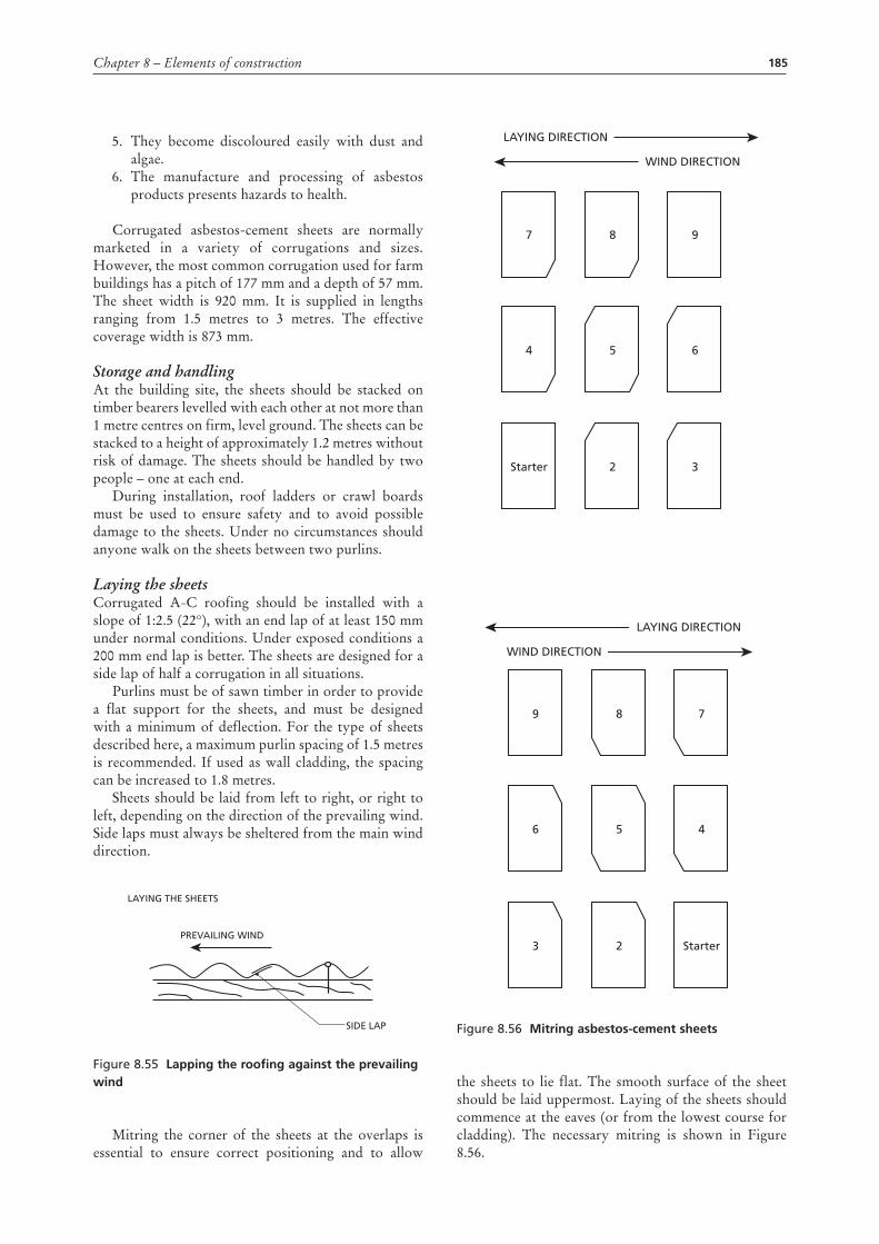
185Chapter 8 – Elements of construction
5. They become discoloured easily with dust and algae.
6. The manufacture and processing of asbestos products presents hazards to health.
Corrugated asbestos-cement sheets are normally marketed in a variety of corrugations and sizes. However, the most common corrugation used for farm buildings has a pitch of 177 mm and a depth of 57 mm. The sheet width is 920 mm. It is supplied in lengths ranging from 1.5 metres to 3 metres. The effective coverage width is 873 mm.
Storage and handlingAt the building site, the sheets should be stacked on timber bearers levelled with each other at not more than 1 metre centres on firm, level ground. The sheets can be stacked to a height of approximately 1.2 metres without risk of damage. The sheets should be handled by two people – one at each end.
During installation, roof ladders or crawl boards must be used to ensure safety and to avoid possible damage to the sheets. Under no circumstances should anyone walk on the sheets between two purlins.
Laying the sheetsCorrugated A-C roofing should be installed with a slope of 1:2.5 (22°), with an end lap of at least 150 mm under normal conditions. Under exposed conditions a 200 mm end lap is better. The sheets are designed for a side lap of half a corrugation in all situations.
Purlins must be of sawn timber in order to provide a flat support for the sheets, and must be designed with a minimum of deflection. For the type of sheets described here, a maximum purlin spacing of 1.5 metres is recommended. If used as wall cladding, the spacing can be increased to 1.8 metres.
Sheets should be laid from left to right, or right to left, depending on the direction of the prevailing wind. Side laps must always be sheltered from the main wind direction.
Figure 8.55 Lapping the roofing against the prevailing wind
Mitring the corner of the sheets at the overlaps is essential to ensure correct positioning and to allow
LAYING THE SHEETS
PREVAILING WIND
SIDE LAP
the sheets to lie flat. The smooth surface of the sheet should be laid uppermost. Laying of the sheets should commence at the eaves (or from the lowest course for cladding). The necessary mitring is shown in Figure 8.56.
Figure 8.56 mitring asbestos-cement sheets
LAYING DIRECTION
WIND DIRECTION
7 8 9
4 5 6
Starter 2 3
LAYING DIRECTION
WIND DIRECTION
9 8 7
6 5 4
3 Starter2
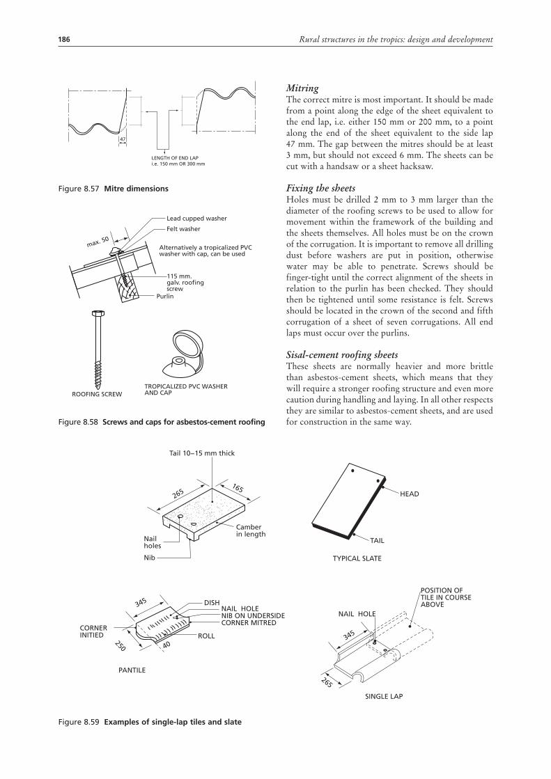
186 Rural structures in the tropics: design and development
Figure 8.57 mitre dimensions
Figure 8.58 screws and caps for asbestos-cement roofing
LENGTH OF END LAPi.e. 150 mm OR 300 mm
47
Lead cupped washer
Felt washer
TROPICALIZED PVC WASHER AND CAP
115 mm.galv. roofingscrew
ROOFING SCREW
Purlin
max. 50Alternatively a tropicalized PVC washer with cap, can be used
MitringThe correct mitre is most important. It should be made from a point along the edge of the sheet equivalent to the end lap, i.e. either 150 mm or 200 mm, to a point along the end of the sheet equivalent to the side lap 47 mm. The gap between the mitres should be at least 3 mm, but should not exceed 6 mm. The sheets can be cut with a handsaw or a sheet hacksaw.
Fixing the sheetsHoles must be drilled 2 mm to 3 mm larger than the diameter of the roofing screws to be used to allow for movement within the framework of the building and the sheets themselves. All holes must be on the crown of the corrugation. It is important to remove all drilling dust before washers are put in position, otherwise water may be able to penetrate. Screws should be finger-tight until the correct alignment of the sheets in relation to the purlin has been checked. They should then be tightened until some resistance is felt. Screws should be located in the crown of the second and fifth corrugation of a sheet of seven corrugations. All end laps must occur over the purlins.
Sisal-cement roofing sheetsThese sheets are normally heavier and more brittle than asbestos-cement sheets, which means that they will require a stronger roofing structure and even more caution during handling and laying. In all other respects they are similar to asbestos-cement sheets, and are used for construction in the same way.
Figure 8.59 Examples of single-lap tiles and slate
Tail 10−15 mm thick
Nailholes
Nib
Camberin length
165265 HEAD
TAIL
TYPICAL SLATE
DISH
ROLL
NAIL HOLENIB ON UNDERSIDECORNER MITRED
250
345
40
CORNER INITIED
PANTILE
NAIL HOLE
SINGLE LAP
POSITION OFTILE IN COURSEABOVE
265
345
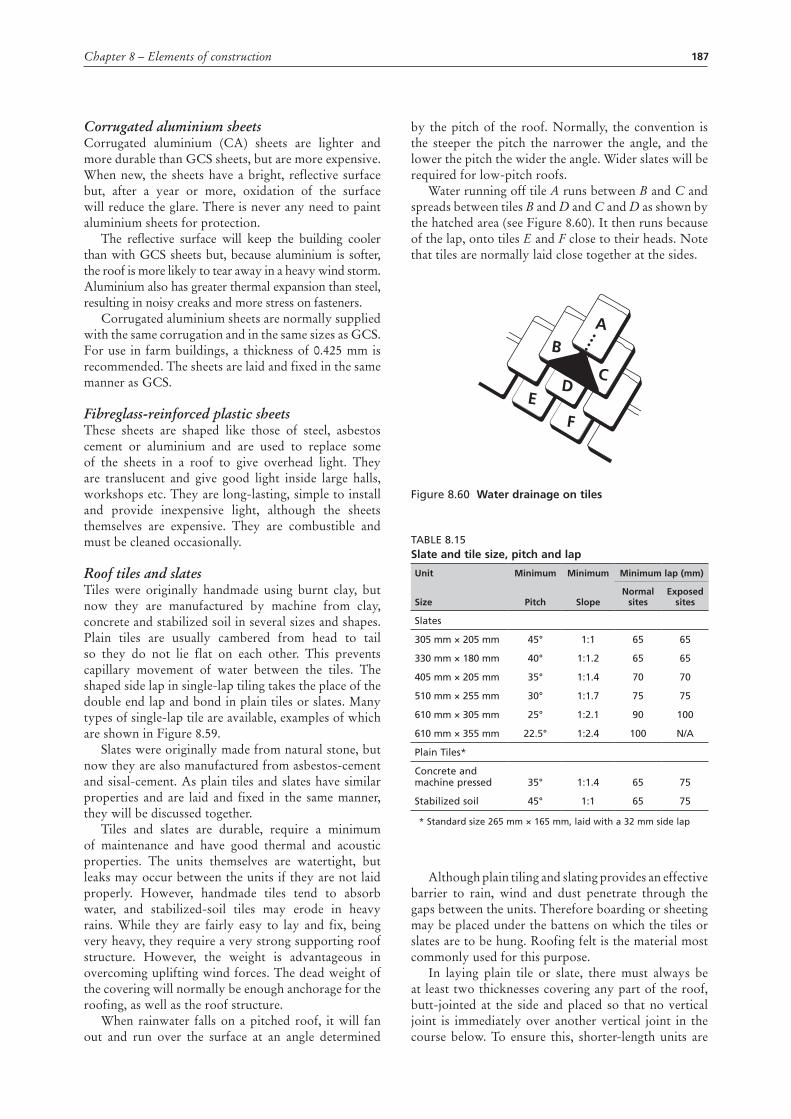
187Chapter 8 – Elements of construction
Corrugated aluminium sheetsCorrugated aluminium (CA) sheets are lighter and more durable than GCS sheets, but are more expensive. When new, the sheets have a bright, reflective surface but, after a year or more, oxidation of the surface will reduce the glare. There is never any need to paint aluminium sheets for protection.
The reflective surface will keep the building cooler than with GCS sheets but, because aluminium is softer, the roof is more likely to tear away in a heavy wind storm. Aluminium also has greater thermal expansion than steel, resulting in noisy creaks and more stress on fasteners.
Corrugated aluminium sheets are normally supplied with the same corrugation and in the same sizes as GCS. For use in farm buildings, a thickness of 0.425 mm is recommended. The sheets are laid and fixed in the same manner as GCS.
Fibreglass-reinforced plastic sheetsThese sheets are shaped like those of steel, asbestos cement or aluminium and are used to replace some of the sheets in a roof to give overhead light. They are translucent and give good light inside large halls, workshops etc. They are long-lasting, simple to install and provide inexpensive light, although the sheets themselves are expensive. They are combustible and must be cleaned occasionally.
Roof tiles and slatesTiles were originally handmade using burnt clay, but now they are manufactured by machine from clay, concrete and stabilized soil in several sizes and shapes. Plain tiles are usually cambered from head to tail so they do not lie flat on each other. This prevents capillary movement of water between the tiles. The shaped side lap in single-lap tiling takes the place of the double end lap and bond in plain tiles or slates. Many types of single-lap tile are available, examples of which are shown in Figure 8.59.
Slates were originally made from natural stone, but now they are also manufactured from asbestos-cement and sisal-cement. As plain tiles and slates have similar properties and are laid and fixed in the same manner, they will be discussed together.
Tiles and slates are durable, require a minimum of maintenance and have good thermal and acoustic properties. The units themselves are watertight, but leaks may occur between the units if they are not laid properly. However, handmade tiles tend to absorb water, and stabilized-soil tiles may erode in heavy rains. While they are fairly easy to lay and fix, being very heavy, they require a very strong supporting roof structure. However, the weight is advantageous in overcoming uplifting wind forces. The dead weight of the covering will normally be enough anchorage for the roofing, as well as the roof structure.
When rainwater falls on a pitched roof, it will fan out and run over the surface at an angle determined
by the pitch of the roof. Normally, the convention is the steeper the pitch the narrower the angle, and the lower the pitch the wider the angle. Wider slates will be required for low-pitch roofs.
Water running off tile A runs between B and C and spreads between tiles B and D and C and D as shown by the hatched area (see Figure 8.60). It then runs because of the lap, onto tiles E and F close to their heads. Note that tiles are normally laid close together at the sides.
Figure 8.60 Water drainage on tiles
Table 8.15slate and tile size, pitch and lap
unit minimum minimum minimum lap (mm)
size pitch slopenormal
sites Exposed
sites
Slates
305 mm × 205 mm 45° 1:1 65 65
330 mm × 180 mm 40° 1:1.2 65 65
405 mm × 205 mm 35° 1:1.4 70 70
510 mm × 255 mm 30° 1:1.7 75 75
610 mm × 305 mm 25° 1:2.1 90 100
610 mm × 355 mm 22.5° 1:2.4 100 N/a
Plain Tiles*
Concrete and machine pressed 35° 1:1.4 65 75
Stabilized soil 45° 1:1 65 75
* Standard size 265 mm × 165 mm, laid with a 32 mm side lap
Although plain tiling and slating provides an effective barrier to rain, wind and dust penetrate through the gaps between the units. Therefore boarding or sheeting may be placed under the battens on which the tiles or slates are to be hung. Roofing felt is the material most commonly used for this purpose.
In laying plain tile or slate, there must always be at least two thicknesses covering any part of the roof, butt-jointed at the side and placed so that no vertical joint is immediately over another vertical joint in the course below. To ensure this, shorter-length units are
AB
CD
EF
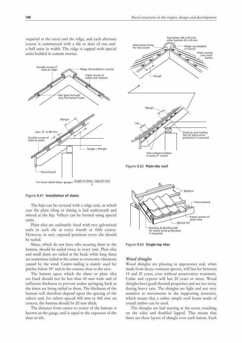
188 Rural structures in the tropics: design and development
required at the eaves and the ridge, and each alternate course is commenced with a tile or slate of one-and-a-half units in width. The ridge is capped with special units bedded in cement mortar.
Figure 8.61 Installation of slates
The hips can be covered with a ridge unit, in which case the plain tiling or slating is laid underneath and mitred at the hip. Valleys can be formed using special units.
Plain tiles are ordinarily fixed with two galvanized nails in each tile at every fourth or fifth course. However, in very exposed positions every tile should be nailed.
Slates, which do not have nibs securing them to the battens, should be nailed twice in every unit. Plain tiles and small slates are nailed at the head, while long slates are sometimes nailed at the centre to overcome vibrations caused by the wind. Centre-nailing is mainly used for pitches below 35° and in the courses close to the eave.
The battens upon which the slates or plain tiles are fixed should not be less than 40 mm wide and of sufficient thickness to prevent undue springing back as the slates are being nailed to them. The thickness of the battens will therefore depend upon the spacing of the rafters and, for rafters spaced 400 mm to 460 mm on centres, the battens should be 20 mm thick.
The distance from centre to centre of the battens is known as the gauge, and is equal to the exposure of the slate or tile.
Double course ofslate at ridge
Double course of slate at eaves
Gauge = Margin
Fascia board
Ridge tile bedded in mortar
Triple course ofslates over battens
Nail goes throughonly the bottom slate
Margin
Lap= 75 to 80 mm
For head nailed slates: gauge= length of slates - (lap+25 mm)2
Figure 8.62 plain-tile roof
Figure 8.63 single-lap tiles
Wood shinglesWood shingles are pleasing in appearance and, when made from decay-resistant species, will last for between 15 and 20 years, even without preservative treatment. Cedar and cypress will last 20 years or more. Wood shingles have good thermal properties and are not noisy during heavy rain. The shingles are light and not very sensitive to movements in the supporting structure, which means that a rather simple roof frame made of round timber can be used.
The shingles are laid starting at the eaves, touching on the sides and doubled lapped. This means that there are three layers of shingle over each batten. Each
Lap
Margin
Gauge
Alternative fixingfor top course
Top batten (40 x 20 mm)other battens 20 x 20 mm
Ridge cap beddedin mortar
Triple coursesover each
batten
Decking and roofingfelt for extra windprotection if required
Tiles nailed to battenin every 4th course
Battens
Fascia board
Eaves course of plain tiles
Mortal fill
Decking & Roofing feltfor extra wind protectionif required
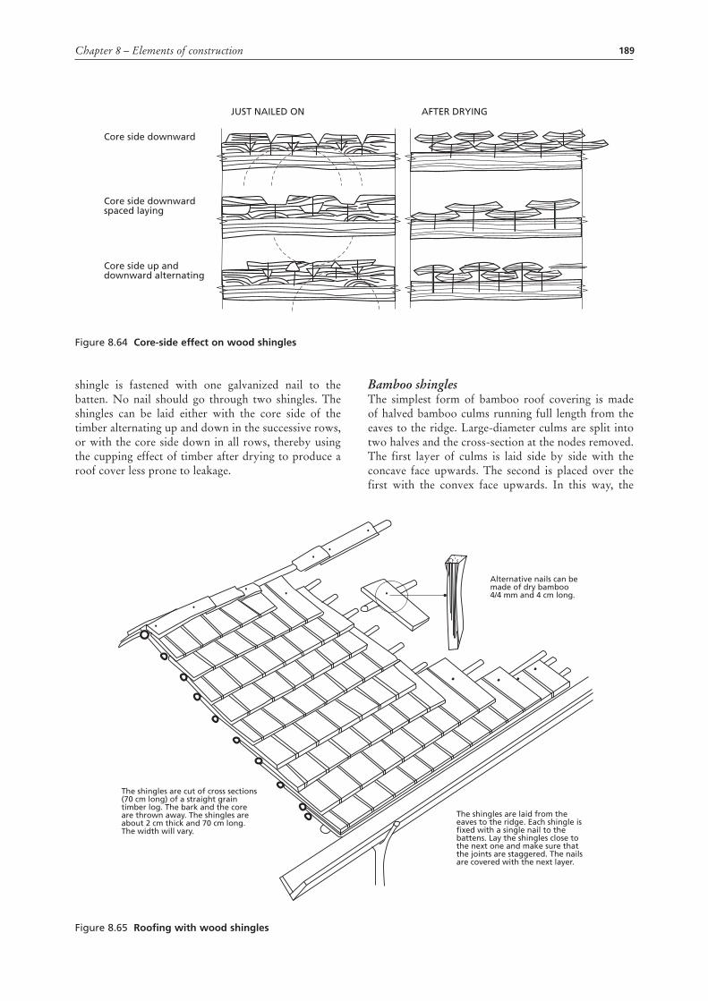
189Chapter 8 – Elements of construction
shingle is fastened with one galvanized nail to the batten. No nail should go through two shingles. The shingles can be laid either with the core side of the timber alternating up and down in the successive rows, or with the core side down in all rows, thereby using the cupping effect of timber after drying to produce a roof cover less prone to leakage.
Bamboo shinglesThe simplest form of bamboo roof covering is made of halved bamboo culms running full length from the eaves to the ridge. Large-diameter culms are split into two halves and the cross-section at the nodes removed. The first layer of culms is laid side by side with the concave face upwards. The second is placed over the first with the convex face upwards. In this way, the
Figure 8.64 core-side effect on wood shingles
Core side downward
JUST NAILED ON AFTER DRYING
Core side downwardspaced laying
Core side up anddownward alternating
Figure 8.65 roofing with wood shingles
Alternative nails can be made of dry bamboo4/4 mm and 4 cm long.
The shingles are cut of cross sections(70 cm long) of a straight graintimber log. The bark and the coreare thrown away. The shingles areabout 2 cm thick and 70 cm long.The width will vary.
The shingles are laid from theeaves to the ridge. Each shingle isfixed with a single nail to thebattens. Lay the shingles close tothe next one and make sure thatthe joints are staggered. The nailsare covered with the next layer.
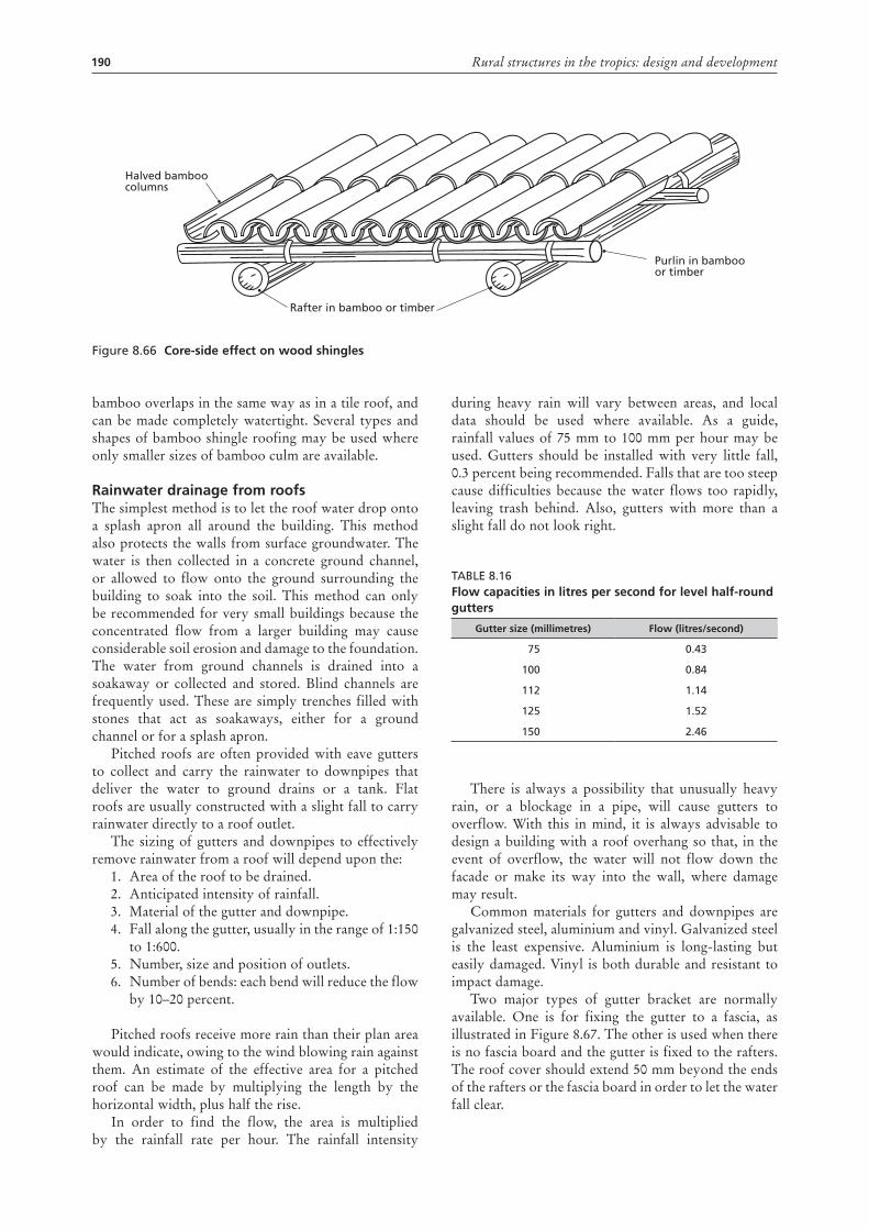
190 Rural structures in the tropics: design and development
bamboo overlaps in the same way as in a tile roof, and can be made completely watertight. Several types and shapes of bamboo shingle roofing may be used where only smaller sizes of bamboo culm are available.
rainwater drainage from roofsThe simplest method is to let the roof water drop onto a splash apron all around the building. This method also protects the walls from surface groundwater. The water is then collected in a concrete ground channel, or allowed to flow onto the ground surrounding the building to soak into the soil. This method can only be recommended for very small buildings because the concentrated flow from a larger building may cause considerable soil erosion and damage to the foundation. The water from ground channels is drained into a soakaway or collected and stored. Blind channels are frequently used. These are simply trenches filled with stones that act as soakaways, either for a ground channel or for a splash apron.
Pitched roofs are often provided with eave gutters to collect and carry the rainwater to downpipes that deliver the water to ground drains or a tank. Flat roofs are usually constructed with a slight fall to carry rainwater directly to a roof outlet.
The sizing of gutters and downpipes to effectively remove rainwater from a roof will depend upon the:
1. Area of the roof to be drained. 2. Anticipated intensity of rainfall. 3. Material of the gutter and downpipe. 4. Fall along the gutter, usually in the range of 1:150
to 1:600. 5. Number, size and position of outlets. 6. Number of bends: each bend will reduce the flow
by 10–20 percent.
Pitched roofs receive more rain than their plan area would indicate, owing to the wind blowing rain against them. An estimate of the effective area for a pitched roof can be made by multiplying the length by the horizontal width, plus half the rise.
In order to find the flow, the area is multiplied by the rainfall rate per hour. The rainfall intensity
during heavy rain will vary between areas, and local data should be used where available. As a guide, rainfall values of 75 mm to 100 mm per hour may be used. Gutters should be installed with very little fall, 0.3 percent being recommended. Falls that are too steep cause difficulties because the water flows too rapidly, leaving trash behind. Also, gutters with more than a slight fall do not look right.
Table 8.16Flow capacities in litres per second for level half-round gutters
gutter size (millimetres) Flow (litres/second)
75 0.43
100 0.84
112 1.14
125 1.52
150 2.46
There is always a possibility that unusually heavy rain, or a blockage in a pipe, will cause gutters to overflow. With this in mind, it is always advisable to design a building with a roof overhang so that, in the event of overflow, the water will not flow down the facade or make its way into the wall, where damage may result.
Common materials for gutters and downpipes are galvanized steel, aluminium and vinyl. Galvanized steel is the least expensive. Aluminium is long-lasting but easily damaged. Vinyl is both durable and resistant to impact damage.
Two major types of gutter bracket are normally available. One is for fixing the gutter to a fascia, as illustrated in Figure 8.67. The other is used when there is no fascia board and the gutter is fixed to the rafters. The roof cover should extend 50 mm beyond the ends of the rafters or the fascia board in order to let the water fall clear.
Figure 8.66 core-side effect on wood shingles
Purlin in bambooor timber
Rafter in bamboo or timber
Halved bamboo columns
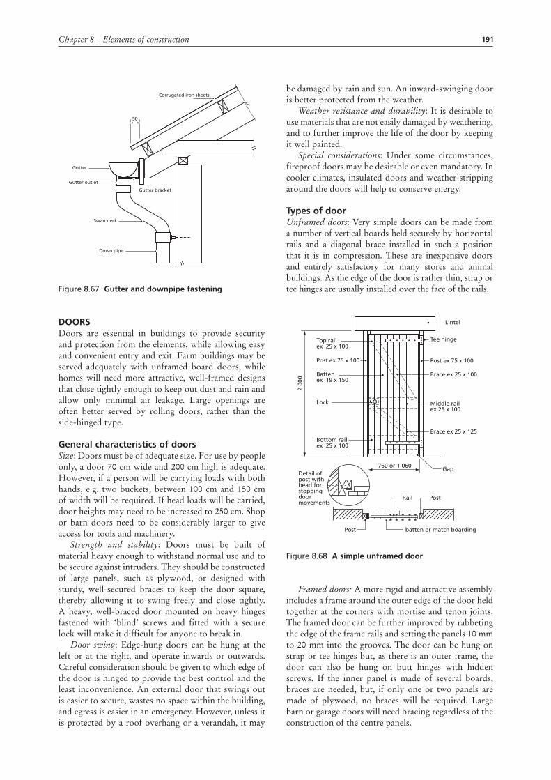
191Chapter 8 – Elements of construction
Figure 8.67 gutter and downpipe fastening
doorsDoors are essential in buildings to provide security and protection from the elements, while allowing easy and convenient entry and exit. Farm buildings may be served adequately with unframed board doors, while homes will need more attractive, well-framed designs that close tightly enough to keep out dust and rain and allow only minimal air leakage. Large openings are often better served by rolling doors, rather than the side-hinged type.
general characteristics of doorsSize: Doors must be of adequate size. For use by people only, a door 70 cm wide and 200 cm high is adequate. However, if a person will be carrying loads with both hands, e.g. two buckets, between 100 cm and 150 cm of width will be required. If head loads will be carried, door heights may need to be increased to 250 cm. Shop or barn doors need to be considerably larger to give access for tools and machinery.
Strength and stability: Doors must be built of material heavy enough to withstand normal use and to be secure against intruders. They should be constructed of large panels, such as plywood, or designed with sturdy, well-secured braces to keep the door square, thereby allowing it to swing freely and close tightly. A heavy, well-braced door mounted on heavy hinges fastened with ‘blind’ screws and fitted with a secure lock will make it difficult for anyone to break in.
Door swing: Edge-hung doors can be hung at the left or at the right, and operate inwards or outwards. Careful consideration should be given to which edge of the door is hinged to provide the best control and the least inconvenience. An external door that swings out is easier to secure, wastes no space within the building, and egress is easier in an emergency. However, unless it is protected by a roof overhang or a verandah, it may
Down pipe
Swan neck
Gutter outlet
Gutter bracket
Gutter
Corrugated iron sheets
50
be damaged by rain and sun. An inward-swinging door is better protected from the weather.
Weather resistance and durability: It is desirable to use materials that are not easily damaged by weathering, and to further improve the life of the door by keeping it well painted.
Special considerations: Under some circumstances, fireproof doors may be desirable or even mandatory. In cooler climates, insulated doors and weather-stripping around the doors will help to conserve energy.
types of doorUnframed doors: Very simple doors can be made from a number of vertical boards held securely by horizontal rails and a diagonal brace installed in such a position that it is in compression. These are inexpensive doors and entirely satisfactory for many stores and animal buildings. As the edge of the door is rather thin, strap or tee hinges are usually installed over the face of the rails.
Figure 8.68 a simple unframed door
Framed doors: A more rigid and attractive assembly includes a frame around the outer edge of the door held together at the corners with mortise and tenon joints. The framed door can be further improved by rabbeting the edge of the frame rails and setting the panels 10 mm to 20 mm into the grooves. The door can be hung on strap or tee hinges but, as there is an outer frame, the door can also be hung on butt hinges with hidden screws. If the inner panel is made of several boards, braces are needed, but, if only one or two panels are made of plywood, no braces will be required. Large barn or garage doors will need bracing regardless of the construction of the centre panels.
Lintel
Tee hinge
Post ex 75 x 100
Top railex 25 x 100
Bottom railex 25 x 100
Detail ofpost withbead forstopping doormovements
Post batten or match boarding
Post ex 75 x 100
Battenex 19 x 150
Lock
2 00
0
Brace ex 25 x 125
760 or 1 060 Gap
PostRail
Brace ex 25 x 100
Middle railex 25 x 100
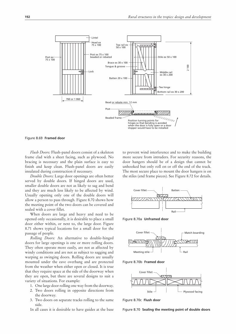
192 Rural structures in the tropics: design and development
Flush Doors: Flush-panel doors consist of a skeleton frame clad with a sheet facing, such as plywood. No bracing is necessary and the plain surface is easy to finish and keep clean. Flush-panel doors are easily insulated during construction if necessary.
Double Doors: Large door openings are often better served by double doors. If hinged doors are used, smaller double doors are not as likely to sag and bend and they are much less likely to be affected by wind. Usually opening only one of the double doors will allow a person to pass through. Figure 8.70 shows how the meeting point of the two doors can be covered and sealed with a cover fillet.
When doors are large and heavy and need to be opened only occasionally, it is desirable to place a small door either within, or next to, the large door. Figure 8.71 shows typical locations for a small door for the passage of people.
Rolling Doors: An alternative to double-hinged doors for large openings is one or more rolling doors. They often operate more easily, are not as affected by windy conditions and are not as subject to sagging and warping as swinging doors. Rolling doors are usually mounted under the eave overhang and are protected from the weather when either open or closed. It is true that they require space at the side of the doorway when they are open, but there are several designs to suit a variety of situations. For example:
1. One large door rolling one way from the doorway. 2. Two doors rolling in opposite directions from
the doorway. 3. Two doors on separate tracks rolling to the same
side. In all cases it is desirable to have guides at the base
to prevent wind interference and to make the building more secure from intruders. For security reasons, the door hangers should be of a design that cannot be unhooked but only roll on or off the end of the track. The most secure place to mount the door hangers is on the stiles (end frame pieces). See Figure 8.72 for details.
Figure 8.70a unframed door
Figure 8.70b Framed door
Figure 8.70c Flush door
Figure 8.70 sealing the meeting point of double doors
Cover fillet Batten
Rail
Cover fillet
Meeting stile
Match boarding
Rail
Cover fillet
Stile Plywood facing
Figure 8.69 Framed door
Post ex75 x 100
Head ex 75 x 100 Top rail ex
50 x 100
Brace ex 30 x 100
Stile ex 50 x 100
Middle rail ex 30 x 200
Tee hinge
Bottom rail ex 30 x 200
Bead or rebate min. 12 mm
Beaded framePosition turning points forhinges so that bending is avoidedwhen the door is fully open or a doorstopper would have to be installed
Post
Batten 20 x 100
2 10
0Tongue & groove
Post ex 75 x 100beaded or rebated
Lock
760 or 1 060
Lintel
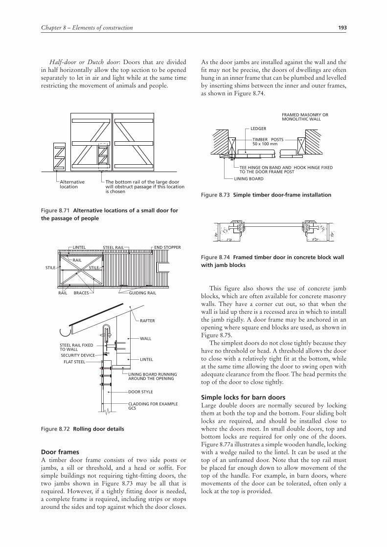
193Chapter 8 – Elements of construction
Half-door or Dutch door: Doors that are divided in half horizontally allow the top section to be opened separately to let in air and light while at the same time restricting the movement of animals and people.
Figure 8.71 alternative locations of a small door for the passage of people
Figure 8.72 rolling door details
door framesA timber door frame consists of two side posts or jambs, a sill or threshold, and a head or soffit. For simple buildings not requiring tight-fitting doors, the two jambs shown in Figure 8.73 may be all that is required. However, if a tightly fitting door is needed, a complete frame is required, including strips or stops around the sides and top against which the door closes.
Alternative location
The bottom rail of the large doorwill obstruct passage if this locationis chosen
RAFTER
GUIDING RAIL
STEEL RAIL END STOPPERLINTEL
RAIL
RAIL
BRACES
STILE STILE
SECURITY DEVICE
WALL
LINTEL
LINING BOARD RUNNINGAROUND THE OPENING
DOOR STYLE
CLADDING FOR EXAMPLEGCS
FLAT STEEL
STEEL RAIL FIXEDTO WALL
As the door jambs are installed against the wall and the fit may not be precise, the doors of dwellings are often hung in an inner frame that can be plumbed and levelled by inserting shims between the inner and outer frames, as shown in Figure 8.74.
Figure 8.73 simple timber door-frame installation
Figure 8.74 Framed timber door in concrete block wall with jamb blocks
This figure also shows the use of concrete jamb blocks, which are often available for concrete masonry walls. They have a corner cut out, so that when the wall is laid up there is a recessed area in which to install the jamb rigidly. A door frame may be anchored in an opening where square end blocks are used, as shown in Figure 8.75.
The simplest doors do not close tightly because they have no threshold or head. A threshold allows the door to close with a relatively tight fit at the bottom, while at the same time allowing the door to swing open with adequate clearance from the floor. The head permits the top of the door to close tightly.
simple locks for barn doorsLarge double doors are normally secured by locking them at both the top and the bottom. Four sliding bolt locks are required, and should be installed close to where the doors meet. In small double doors, top and bottom locks are required for only one of the doors. Figure 8.77a illustrates a simple wooden handle, locking with a wedge nailed to the lintel. It can be used at the top of an unframed door. Note that the top rail must be placed far enough down to allow movement of the top of the handle. For example, in barn doors, where movements of the door can be tolerated, often only a lock at the top is provided.
LEDGER
TIMBER POSTS50 x 100 mm
FRAMED MASONRY ORMONOLITHIC WALL
TEE HINGE ON BAND AND HOOK HINGE FIXED TO THE DOOR FRAME POST
LINING BOARD
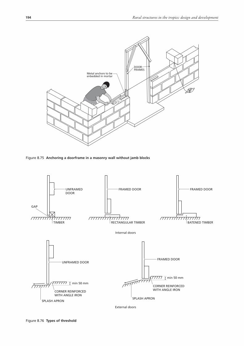
194 Rural structures in the tropics: design and development
Figure 8.75 anchoring a doorframe in a masonry wall without jamb blocks
Metal anchors to be enbedded in mortar
DOORFRAMES
Figure 8.76 types of threshold
UNFRAMEDDOOR
TIMBER
GAP
UNFRAMED DOOR
FRAMED DOOR
RECTANGULAR TIMBER
Internal doors
External doors
FRAMED DOOR
BATENED TIMBER
FRAMED DOOR
SPLASH APRON
CORNER REINFORCEDWITH ANGLE IRON
SPLASH APRON
CORNER REINFORCEDWITH ANGLE IRON
min 50 mm
min 50 mm
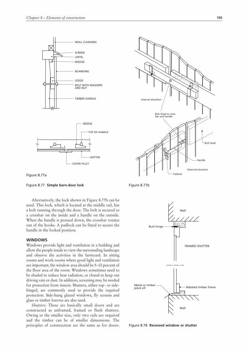
195Chapter 8 – Elements of construction
Figure 8.77a
Figure 8.77 simple barn-door lock
Alternatively, the lock shown in Figure 8.77b can be used. This lock, which is located at the middle rail, has a bolt running through the door. The bolt is secured to a crossbar on the inside and a handle on the outside. When the handle is pressed down, the crossbar rotates out of the hooks. A padlock can be fitted to secure the handle in the locked position.
WIndoWsWindows provide light and ventilation in a building and allow the people inside to view the surrounding landscape and observe the activities in the farmyard. In sitting rooms and work rooms where good light and ventilation are important, the window area should be 5–10 percent of the floor area of the room. Windows sometimes need to be shaded to reduce heat radiation, or closed to keep out driving rain or dust. In addition, screening may be needed for protection from insects. Shutters, either top- or side-hinged, are commonly used to provide the required protection. Side-hung glazed windows, fly screens and glass or timber louvres are also used.
Shutters: These are basically small doors and are constructed as unframed, framed or flush shutters. Owing to the smaller size, only two rails are required and the timber can be of smaller dimensions. The principles of construction are the same as for doors.
WALL CLADDING
SCREEN
LINTEL
WEDGE
LEDGE
TIMBER HANDLE
BOLT WITH WASHERSAND NUT
BOARDING
WEDGE
BATTEN
COVER FILLET
TOP OF HANDLE
Figure 8.77b
Figure 8.78 recessed window or shutter
Internal elevation
External elevation
Bolt fixed to crossbar and handle
Bolt head
Handle
Padlock
Wall
Butt hinge
FRAMED SHUTTER
Rebated timber frame
Wall
Metal or timberpiece sill
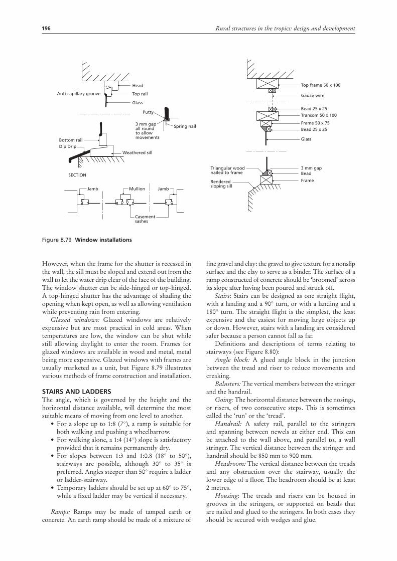
196 Rural structures in the tropics: design and development
However, when the frame for the shutter is recessed in the wall, the sill must be sloped and extend out from the wall to let the water drip clear of the face of the building. The window shutter can be side-hinged or top-hinged. A top-hinged shutter has the advantage of shading the opening when kept open, as well as allowing ventilation while preventing rain from entering.
Glazed windows: Glazed windows are relatively expensive but are most practical in cold areas. When temperatures are low, the window can be shut while still allowing daylight to enter the room. Frames for glazed windows are available in wood and metal, metal being more expensive. Glazed windows with frames are usually marketed as a unit, but Figure 8.79 illustrates various methods of frame construction and installation.
staIrs and LaddErsThe angle, which is governed by the height and the horizontal distance available, will determine the most suitable means of moving from one level to another.
• For a slope up to 1:8 (7°), a ramp is suitable for both walking and pushing a wheelbarrow.
• For walking alone, a 1:4 (14°) slope is satisfactory provided that it remains permanently dry.
• For slopes between 1:3 and 1:0.8 (18° to 50°), stairways are possible, although 30° to 35° is preferred. Angles steeper than 50° require a ladder or ladder-stairway.
• Temporary ladders should be set up at 60° to 75°, while a fixed ladder may be vertical if necessary.
Ramps: Ramps may be made of tamped earth or concrete. An earth ramp should be made of a mixture of
fine gravel and clay: the gravel to give texture for a nonslip surface and the clay to serve as a binder. The surface of a ramp constructed of concrete should be ‘broomed’ across its slope after having been poured and struck off.
Stairs: Stairs can be designed as one straight flight, with a landing and a 90° turn, or with a landing and a 180° turn. The straight flight is the simplest, the least expensive and the easiest for moving large objects up or down. However, stairs with a landing are considered safer because a person cannot fall as far.
Definitions and descriptions of terms relating to stairways (see Figure 8.80):
Angle block: A glued angle block in the junction between the tread and riser to reduce movements and creaking.
Balusters: The vertical members between the stringer and the handrail.
Going: The horizontal distance between the nosings, or risers, of two consecutive steps. This is sometimes called the ‘run’ or the ‘tread’.
Handrail: A safety rail, parallel to the stringers and spanning between newels at either end. This can be attached to the wall above, and parallel to, a wall stringer. The vertical distance between the stringer and handrail should be 850 mm to 900 mm.
Headroom: The vertical distance between the treads and any obstruction over the stairway, usually the lower edge of a floor. The headroom should be at least 2 metres.
Housing: The treads and risers can be housed in grooves in the stringers, or supported on beads that are nailed and glued to the stringers. In both cases they should be secured with wedges and glue.
Figure 8.79 Window installations
Top rail
Glass
Putty
Bottom rail
Jamb JambMullion
Casement sashes
Dip DripWeathered sill
SECTION
3 mm gap all roundto allow movements
Spring nail
Triangular wood nailed to frame
Rendered sloping sill
Head
Anti-capillary groove
Top frame 50 x 100
Gauze wire
Bead 25 x 25
Bead 25 x 25
Glass
3 mm gapBead
Frame
Transom 50 x 100
Frame 50 x 75
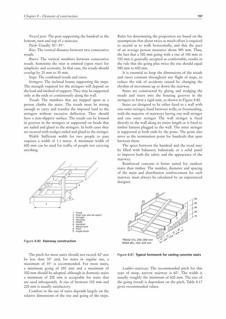
197Chapter 8 – Elements of construction
Newel post: The post supporting the handrail at the bottom, turn and top of a staircase.
Pitch: Usually 30°–35°.Rise: The vertical distance between two consecutive
treads.Risers: The vertical members between consecutive
treads. Sometime the riser is omitted (open riser) for simplicity and economy. In that case, the treads should overlap by 25 mm to 35 mm.
Steps: The combined treads and risers.Stringers: The inclined beams supporting the steps.
The strength required for the stringers will depend on the load and method of support. They may be supported only at the ends or continuously along the wall.
Treads: The members that are stepped upon as a person climbs the stairs. The treads must be strong enough to carry and transfer the imposed load to the stringers without excessive deflection. They should have a non-slippery surface. The treads can be housed in grooves in the stringers or supported on beads that are nailed and glued to the stringers. In both cases they are secured with wedges nailed and glued to the stringer.
Width: Sufficient width for two people to pass requires a width of 1.1 metre. A minimum width of 600 mm can be used for traffic of people not carrying anything.
Figure 8.80 stairway construction
The pitch for most stairs should not exceed 42° nor be less than 30° and, for stairs in regular use, a maximum of 35° is recommended. For most stairs, a minimum going of 250 mm and a maximum of 300 mm should be adopted, although in domestic stairs a minimum of 200 mm is acceptable for stairs that are used infrequently. A rise of between 150 mm and 220 mm is usually satisfactory.
Comfort in the use of stairs depends largely on the relative dimensions of the rise and going of the steps.
1 - Tread2 - Riser (can also be open)3 - Stringer4 - Housing5 - Width6 - Handrail7 - Newel post8 - Pitch9 - Angle block
1
6
3
4
2
9
5
87
Rules for determining the proportion are based on the assumptions that about twice as much effort is required to ascend as to walk horizontally, and that the pace of an average person measures about 585 mm. Thus, the fact that a 300 mm going with a rise of 140 mm or 150 mm is generally accepted as comfortable, results in the rule that the going plus twice the rise should equal 580 mm to 600 mm.
It is essential to keep the dimensions of the treads and risers constant throughout any flight of steps, to reduce the risk of accidents caused by changing the rhythm of movement up or down the stairway.
Stairs are constructed by gluing and wedging the treads and risers into the housing grooves in the stringers to form a rigid unit, as shown in Figure 8.80.
Stairs are designed to be either fixed to a wall with one outer stringer, fixed between walls, or freestanding, with the majority of stairways having one wall stringer and one outer stringer. The wall stringer is fixed directly to the wall along its entire length or is fixed to timber battens plugged to the wall. The outer stringer is supported at both ends by the posts. The posts also serve as the termination point for handrails that span between them.
The space between the handrail and the tread may be filled with balusters, balustrade or a solid panel to improve both the safety and the appearance of the stairway.
Reinforced concrete is better suited for outdoor stairs than timber. The number, diameter and spacing of the main and distribution reinforcement for each stairway must always be calculated by an experienced designer.
Figure 8.81 typical formwork for casting concrete stairs
Ladder-stairway: The recommended pitch for this type of steep, narrow stairway is 60°. The width is usually roughly the minimum of 600 mm. The size of the going (tread) is dependent on the pitch. Table 8.17 gives recommended values.
5R
4R
3R
2R
1R
1T 2T
3T 4T
TREAD (T)= 250−300 mmRISER (R)= 150−220 mm
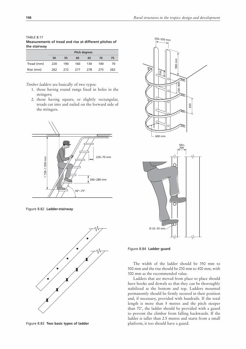
198 Rural structures in the tropics: design and development
Table 8.17measurements of tread and rise at different pitches of the stairway
pitch degrees
50 55 60 65 70 75
Tread (mm) 220 190 160 130 100 70
Rise (mm) 262 272 277 278 275 262
Timber ladders are basically of two types:1. those having round rungs fixed in holes in the
stringers; 2. those having square, or slightly rectangular,
treads cut into and nailed on the forward side of the stringers.
Figure 8.82 Ladder-stairway
Figure 8.83 two basic types of ladder
220−70 mm
50°−75°
260−280 mm
1 73
0−1
930
mm
Figure 8.84 Ladder guard
The width of the ladder should be 350 mm to 500 mm and the rise should be 230 mm to 400 mm, with 300 mm as the recommended value.
Ladders that are moved from place to place should have hooks and dowels so that they can be thoroughly stabilized at the bottom and top. Ladders mounted permanently should be firmly secured in their position and, if necessary, provided with handrails. If the total length is more than 5 metres and the pitch steeper than 70°, the ladder should be provided with a guard to prevent the climber from falling backwards. If the ladder is taller than 2.5 metres and starts from a small platform, it too should have a guard.
900
mm
230−
400
600 mm.
Min.200
Ø 32−35 mm.
650
150
350−550 mm
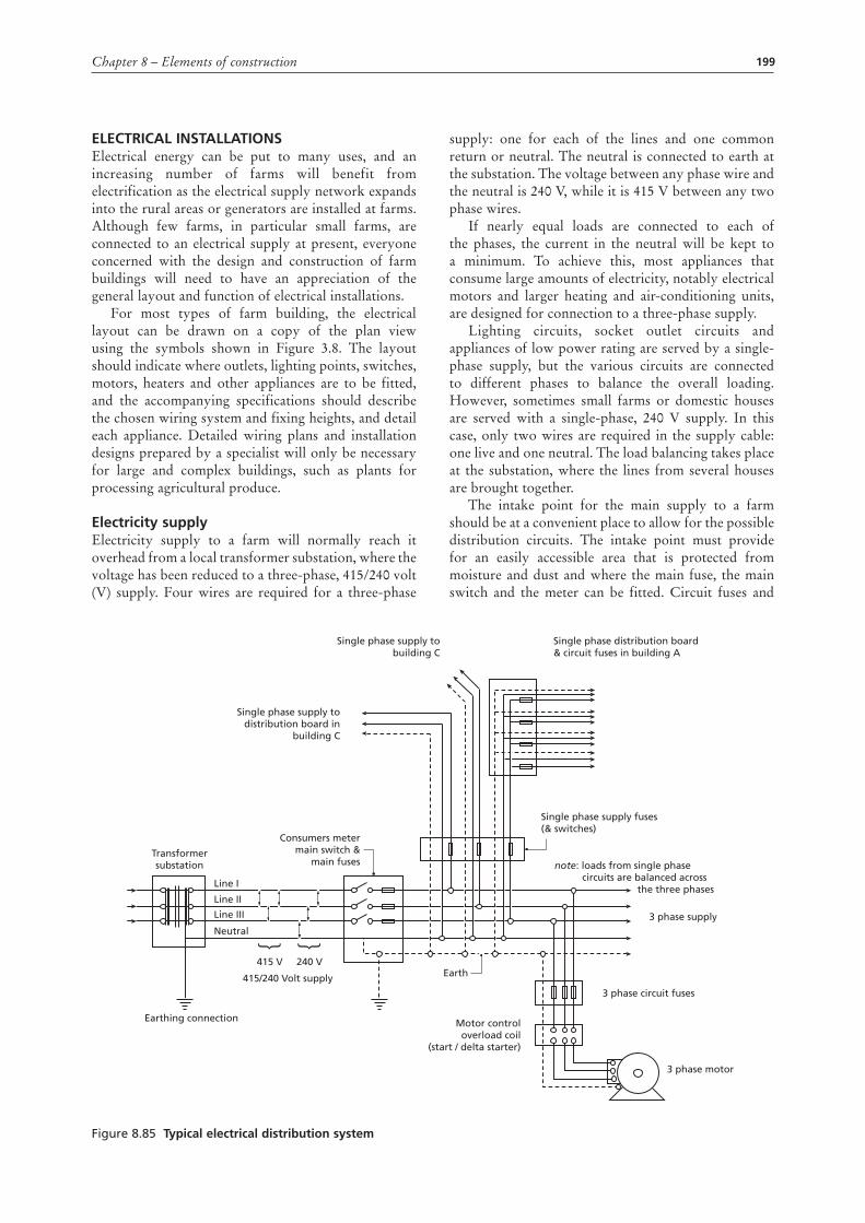
199Chapter 8 – Elements of construction
ELEctrIcaL InstaLLatIonsElectrical energy can be put to many uses, and an increasing number of farms will benefit from electrification as the electrical supply network expands into the rural areas or generators are installed at farms. Although few farms, in particular small farms, are connected to an electrical supply at present, everyone concerned with the design and construction of farm buildings will need to have an appreciation of the general layout and function of electrical installations.
For most types of farm building, the electrical layout can be drawn on a copy of the plan view using the symbols shown in Figure 3.8. The layout should indicate where outlets, lighting points, switches, motors, heaters and other appliances are to be fitted, and the accompanying specifications should describe the chosen wiring system and fixing heights, and detail each appliance. Detailed wiring plans and installation designs prepared by a specialist will only be necessary for large and complex buildings, such as plants for processing agricultural produce.
Electricity supplyElectricity supply to a farm will normally reach it overhead from a local transformer substation, where the voltage has been reduced to a three-phase, 415/240 volt (V) supply. Four wires are required for a three-phase
supply: one for each of the lines and one common return or neutral. The neutral is connected to earth at the substation. The voltage between any phase wire and the neutral is 240 V, while it is 415 V between any two phase wires.
If nearly equal loads are connected to each of the phases, the current in the neutral will be kept to a minimum. To achieve this, most appliances that consume large amounts of electricity, notably electrical motors and larger heating and air-conditioning units, are designed for connection to a three-phase supply.
Lighting circuits, socket outlet circuits and appliances of low power rating are served by a single-phase supply, but the various circuits are connected to different phases to balance the overall loading. However, sometimes small farms or domestic houses are served with a single-phase, 240 V supply. In this case, only two wires are required in the supply cable: one live and one neutral. The load balancing takes place at the substation, where the lines from several houses are brought together.
The intake point for the main supply to a farm should be at a convenient place to allow for the possible distribution circuits. The intake point must provide for an easily accessible area that is protected from moisture and dust and where the main fuse, the main switch and the meter can be fitted. Circuit fuses and
Figure 8.85 typical electrical distribution system
Line I
Transformersubstation
Consumers metermain switch &
main fuses
Earth
3 phase circuit fuses
3 phase supply
note: loads from single phase circuits are balanced across the three phases
Single phase supply fuses(& switches)
3 phase motor
Motor controloverload coil
(start / delta starter)
415 V
415/240 Volt supply
Earthing connection
240 V
Line II
Line III
Neutral } }
Single phase supply todistribution board in
building C
Single phase supply tobuilding C
Single phase distribution board& circuit fuses in building A
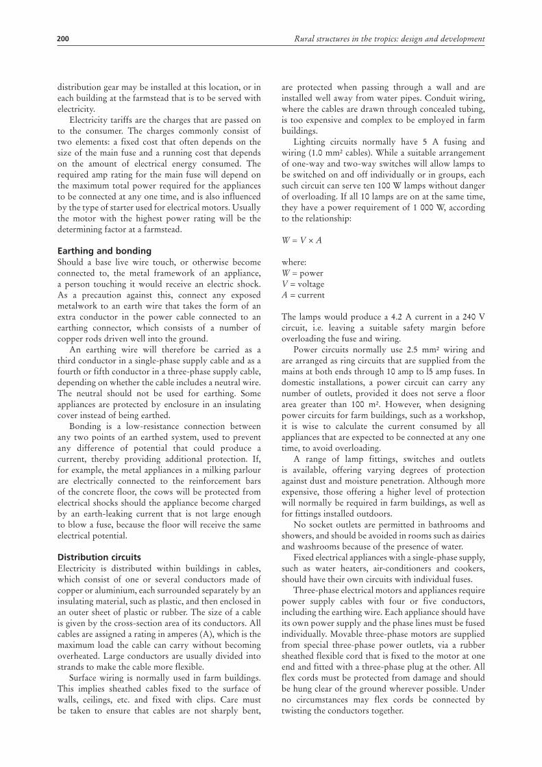
200 Rural structures in the tropics: design and development
distribution gear may be installed at this location, or in each building at the farmstead that is to be served with electricity.
Electricity tariffs are the charges that are passed on to the consumer. The charges commonly consist of two elements: a fixed cost that often depends on the size of the main fuse and a running cost that depends on the amount of electrical energy consumed. The required amp rating for the main fuse will depend on the maximum total power required for the appliances to be connected at any one time, and is also influenced by the type of starter used for electrical motors. Usually the motor with the highest power rating will be the determining factor at a farmstead.
Earthing and bondingShould a base live wire touch, or otherwise become connected to, the metal framework of an appliance, a person touching it would receive an electric shock. As a precaution against this, connect any exposed metalwork to an earth wire that takes the form of an extra conductor in the power cable connected to an earthing connector, which consists of a number of copper rods driven well into the ground.
An earthing wire will therefore be carried as a third conductor in a single-phase supply cable and as a fourth or fifth conductor in a three-phase supply cable, depending on whether the cable includes a neutral wire. The neutral should not be used for earthing. Some appliances are protected by enclosure in an insulating cover instead of being earthed.
Bonding is a low-resistance connection between any two points of an earthed system, used to prevent any difference of potential that could produce a current, thereby providing additional protection. If, for example, the metal appliances in a milking parlour are electrically connected to the reinforcement bars of the concrete floor, the cows will be protected from electrical shocks should the appliance become charged by an earth-leaking current that is not large enough to blow a fuse, because the floor will receive the same electrical potential.
distribution circuitsElectricity is distributed within buildings in cables, which consist of one or several conductors made of copper or aluminium, each surrounded separately by an insulating material, such as plastic, and then enclosed in an outer sheet of plastic or rubber. The size of a cable is given by the cross-section area of its conductors. All cables are assigned a rating in amperes (A), which is the maximum load the cable can carry without becoming overheated. Large conductors are usually divided into strands to make the cable more flexible.
Surface wiring is normally used in farm buildings. This implies sheathed cables fixed to the surface of walls, ceilings, etc. and fixed with clips. Care must be taken to ensure that cables are not sharply bent,
are protected when passing through a wall and are installed well away from water pipes. Conduit wiring, where the cables are drawn through concealed tubing, is too expensive and complex to be employed in farm buildings.
Lighting circuits normally have 5 A fusing and wiring (1.0 mm² cables). While a suitable arrangement of one-way and two-way switches will allow lamps to be switched on and off individually or in groups, each such circuit can serve ten 100 W lamps without danger of overloading. If all 10 lamps are on at the same time, they have a power requirement of 1 000 W, according to the relationship:
W = V × A
where:W = powerV = voltageA = current
The lamps would produce a 4.2 A current in a 240 V circuit, i.e. leaving a suitable safety margin before overloading the fuse and wiring.
Power circuits normally use 2.5 mm² wiring and are arranged as ring circuits that are supplied from the mains at both ends through 10 amp to l5 amp fuses. In domestic installations, a power circuit can carry any number of outlets, provided it does not serve a floor area greater than 100 m². However, when designing power circuits for farm buildings, such as a workshop, it is wise to calculate the current consumed by all appliances that are expected to be connected at any one time, to avoid overloading.
A range of lamp fittings, switches and outlets is available, offering varying degrees of protection against dust and moisture penetration. Although more expensive, those offering a higher level of protection will normally be required in farm buildings, as well as for fittings installed outdoors.
No socket outlets are permitted in bathrooms and showers, and should be avoided in rooms such as dairies and washrooms because of the presence of water.
Fixed electrical appliances with a single-phase supply, such as water heaters, air-conditioners and cookers, should have their own circuits with individual fuses.
Three-phase electrical motors and appliances require power supply cables with four or five conductors, including the earthing wire. Each appliance should have its own power supply and the phase lines must be fused individually. Movable three-phase motors are supplied from special three-phase power outlets, via a rubber sheathed flexible cord that is fixed to the motor at one end and fitted with a three-phase plug at the other. All flex cords must be protected from damage and should be hung clear of the ground wherever possible. Under no circumstances may flex cords be connected by twisting the conductors together.
201Chapter 8 – Elements of construction
artificial lightingIn tropical countries with strong natural light, even relatively small windows can provide sufficient indoor lighting. Artificial lighting will therefore be required mainly to extend the hours of light.
Where electrical energy is available, the two most commonly used artificial light sources are incandescent bulbs and fluorescent tubes. Tubes, and fittings for tubes, are more expensive than bulbs and bulb fittings, but tubes produce three to five times as much light per unit of electrical energy, have up to 10 times the life and generate less heat. Fluorescent light is therefore normally the cheapest option, despite the higher initial cost.
However, in small rooms where the light is switched on and off frequently, bulb fittings are usually preferred, as in this case the installation cost is more important than the energy cost. Mercury vapour and sodium lamps are often used for outdoor lighting. Although they have higher efficiency in terms of the light produced than fluorescent tubes, their light covers only a limited spectrum and tends to distort colours.
Various types of fitting are normally available for both bulbs and tubes. While a naked bulb or tube may be sufficient in some circumstances, fittings that protect the lamp from physical damage and moisture penetration will often be required in farm buildings.
From an optical point of view, the fitting should obscure the lamp and present a larger surface area of lower brightness to reduce the glare caused by excessive luminance contrast. This is particularly important if the lamp is positioned where it will be viewed directly.
A lighting point must also be positioned to avoid reflected glare and unwanted shading of a work area. While light colours on interior surfaces will create a bright room, shades of blue or green produce a feeling of coolness. The dusty conditions in many farm buildings require the use of fittings that are easy to clean. Accumulated dust can reduce the light emitted by more than 50 percent.
Although most agricultural production operations carried out in buildings can be performed quite satisfactorily using natural light, where artificial light is to be installed the standard of illumination should be suited to the activities carried out. While the installation of 2.0 W to 3.0 W of fluorescent light per square metre of floor area will be sufficient for general illumination, work areas need more light (say 5 W/m² to 8 W/m²), and a desk or workbench where concentrated or exacting tasks are performed may need 10 W/m² to 15 W/m², or more. Where bulbs are to be installed instead of tubes, the above values will have to be at least tripled.
Figure 8.86 Examples of light fittings for farm buildings
Bulb
Starter
Flourescent tube
Effective cooling but risk of glarebecause of small luminous area
Plastic opal cover resulting in diffusedlight emitted from larger surface area
Single tube fitting Double tube fitting
Electrical connectionprotected again dust& moisture
Dust proof enclosure
Plastic or porcelain fitting
Glass or plastic opal globeobscuring lamp
Diffused light emitted from larger surface area than the bulb
202 Rural structures in the tropics: design and development
Electrical motorsSingle-phase motors in sizes up to about 1 kilowatt have a wide range of applications, particularly for use in domestic appliances. The most common type, the single-phase series motor or universal motor, produces good starting torque and can be run on either alternating current (AC) or direct current (DC). While it has the advantage of being able to connect to an ordinary socket outlet, generally it cannot compete with the performance and efficiency of a three-phase motor.
The three-phase induction motor is the most common electrical motor at farms, where it is used to power fans, transport devices, mills, etc. Modern electrical motors are manufactured in a wide range of power ratings and types. Types of enclosure range from screen protection to total enclosure. Motors used in farm buildings should normally have an enclosure that is dust-tight and splash-proof, i.e. it should not be damaged by exposure to water splashing from any direction. However, sometimes even better protection is required, such as dust-proofing and flush-proofing, and submersible motors must be totally enclosed and completely waterproof.
Inherent features of the induction motor are its poor starting torque and heavy starting current – up to six times the full load current. To prevent an excessive voltage drop in the supply network, the electricity company usually allows only small induction motors to be started direct on line. A star/delta starter is commonly fitted to motors above 2 kW to 3kW, to reduce the starting current to about twice the full load current. Unfortunately it also reduces the already poor starting torque still further, so that the motor cannot start against heavy load. Other types of motor and starter are available for situations where starting against load cannot be avoided.
The starter for any motor rated above about 0.5 kW must incorporate an overload cut-out that switches off the current if it exceeds a safe value for longer than the time required to start the motor. In many installations it is also desirable to include a release mechanism that prevents an unexpected restart after a power failure. A wide range of sensors, timers and other devices are available for automatic supervision and control of electric-motor operation.
Lightning conductorsLightning striking a building can cause substantial structural damage and may start a fire. Buildings with thatched roofs located in prominent positions present the worst risk, while concrete and steel frame buildings run a low risk. A lightning protection installation has three major parts – an air termination, a down conductor and an earth termination – and its function is to provide a simple and direct path for the lightning to discharge to the ground.
The air termination consists of one or several pointed copper rods fixed above the highest point of
the roof. One down conductor (e.g. 25 mm × 3 mm copper tape) can serve a building of up to 100 m². The earth termination consists of a 10 mm to 12 mm copper-plated rod driven into the ground to a depth of at least 2 metres. If the soil tends to become very dry at any time during the year, additional ground rods driven 2.5 metres deep will offer greater protection.
rEVIEW quEstIons1. What is the role of foundations and footings?2. Why is it necessary to excavate the topsoil before
laying the foundation?3. Briefly describe six types of foundation that may
be used in the building of a rural structure.4. Describe five types of protective material for
foundations.5. Outline the factors that determine the type of
walls used for a building.6. Briefly describe four types of floor and roof.7. Outline three types of roofing material, describing
their advantages and disadvantages.8. What are the general characteristics of doors?9. Why is earthing and bonding important in
electrical supply?
203Chapter 8 – Elements of construction
FurtHEr rEadIngBarnes, M.M. 1971. Farm construction: buildings.
Slough, Cement and Concrete Association.Barry, R. 1969-1972. The construction of buildings.
Volume 14. London, Granada Publishing Ltd.Building Research Establishment (Overseas Division).
1972. Building in earthquake areas. Overseas Building Notes No. 143. Garston, Watford.
Burberry, P. 1979. Environment and services. Mitchell’s Building Series. London, BT Batsford Ltd.
Chudley R. & Greeno R. 2010. Building construction handbook. 8th edition. Oxford, Elsevier.
Chudley, R. 1973–1976. Construction technology. Volume 1-3. London, Longman Group Ltd.
Dancy, H.K. 1975. A Manual of building construction. London, Intermediate Technology Publications Ltd.
Foster, J.S. & Harington, R. 1977. Structure and fabric. Part 2. Mitchell’s Building Series. London, BT Batsford Ltd.
Foster, J.S. 1979. Structure and fabric. Part 1. Mitchell’s Building Series. London, BT Batsford Ltd.
Fullerton, R.L. 1977–1979. Building construction in warm climates. Part 1-3. Oxford, Oxford University Press.
German Appropriate Technology Exchange. 1982. Building instructions for an adobe brick house. Munich, German Agency for Technical Cooperation (GTZ).
Harrison, L.G, III & Lstiburek, J.W. 2009. ASHRAE guide for buildings in hot and humid climates. 2nd edition. ASHRAE.
Haugum, K. 1980. Construction of farm buildings. Nairobi, Housing Research and Development Unit, University of Nairobi.
Janssen, J.J.A. 1982. Bamboo. CICA publication 82.03. Eindhoven, Eindhoven University of Technology.
King, H., revised by Osbourn, D. 1979. Components. Mitchell’s Building series. London, BT Batsford Ltd.
Lippsmeier, G. 1969. Tropenbau – building in the Tropics. Munich, Callwey Verlag.
Longland, F. & Stern, P. (ed.). 1983. Field engineering: an introduction to development work and construction in rural areas. London, Intermediate Technology Publications Ltd.
Ministry of Agriculture and Water Development (Engineering Section). 1984. Grass thatched roofs. Lusaka, Zambia.
Mukerji, K., Whipple, J.H. & Escobar, R.C. 1982. Roof constructions for housing in developing countries. Report on a research study in Central America, 1979. Eschborn, German Appropriate Technology Exchange.
National Vocational Training Institute, Accra. Rural building: 1. Reference book, 2. Basic knowledge, 3. Construction. 4. Drawing book. Maastricht, Stichting Kongretatie F.l.C.
Neidle, M. 1982. Electrical installation technology. 3rd edition. London, Butterworth & Co., Ltd.
Noton, N.H. 1982. Farm buildings. Reading, College of Estate Management.
Osbourn, D. & Greeno, R. 2007. Introduction to building. 4th edition. London, Pearson Education, Prentice Hall.
Schreckenbach, H. & Abankwa, J.G.K. 1982. Construction technology for a developing country. Eschborn, German Agency for Technical Cooperation (GTZ).
Sode, O.J. 1975. Construction of farm buildings. Lusaka, Ministry of Agriculture and Water Development, Engineering Section.
United Nations (Department of Economic and Social Affairs). 1975. Low-cost construction resistant to earthquake and hurricanes. New York.
Whitaker, J.H. 1979. Agricultural buildings and structures. Reston, Reston Publishing Co.