Embed Size (px)
Citation preview

J.J. Shann
Chapter 7
Registers &
Register TransfersJ. J. Shann
J.J. Shann 7-2
Chapter Overview7-1 Registers and Load Enable7-2 Register Transfers7-3 Register Transfer Operations7-4 A Note for VHDL and Verilog Users Only7-5 Microoperations7-6 Microoperatrions on a Single Register7-7 Register Cell Design7-8 Multiplexer and Bus-Based Transfer for Multiple
Registers7-9 Serial Transfer and Microoperations7-10 HDL Representation for Shift Registes and Counters—
VHDL7-11 HDL Representation for Shift Registes and Counters—
Verilog7-12 Chapter Summary

J.J. Shann 7-3
Part I: Registers and Counters7-1 Registers and Load Enable7-6 Microoperatrions on a Single Register
(Shift registers, Ripple counter, Synchronous binary counters, other counters)
Part II: Register Transfers7-2 Register Transfers7-3 Register Transfer Operations7-5 Microoperations7-7 Register Cell Design7-6 Microoperatrions on a Single Register
(Multiplexer-Based Transfers)7-8 Multiplexer and Bus-Based Transfer for Multiple Registers7-9 Serial Transfer and Microoperations
7-12 Chapter Summary
J.J. Shann
Part I
Registers and Counters
J.J. Shann 7-5
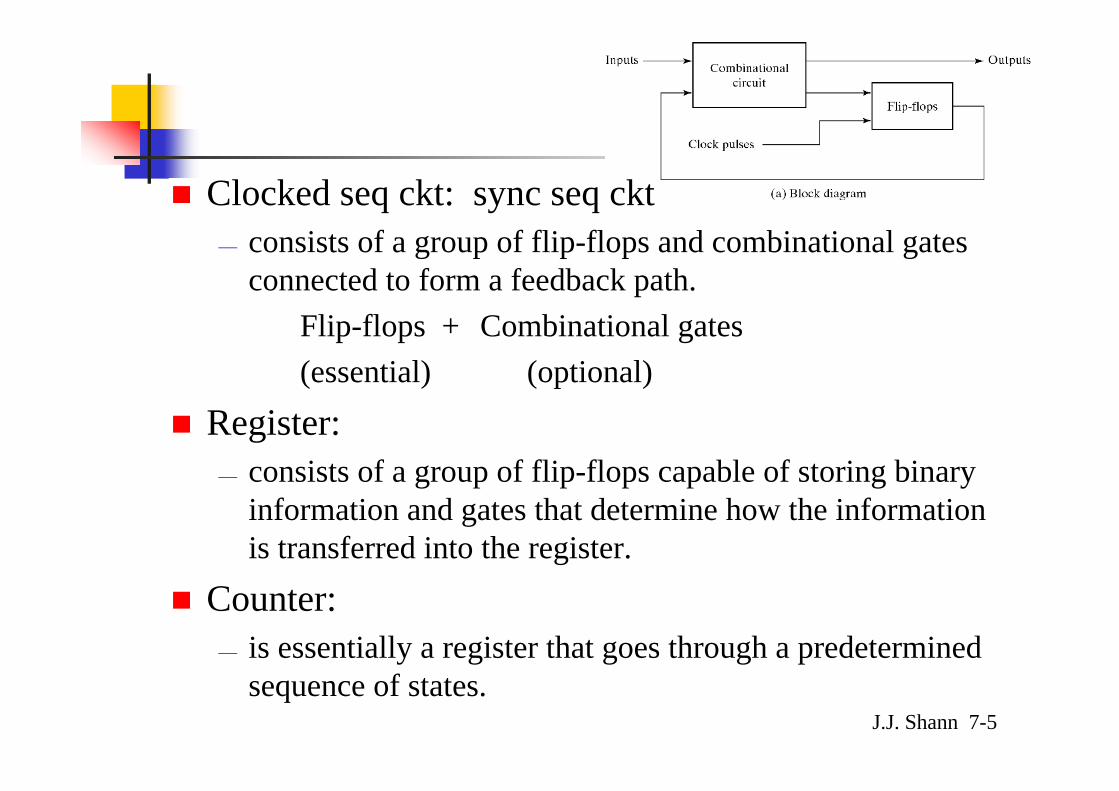
Clocked seq ckt: sync seq ckt— consists of a group of flip-flops and combinational gates
connected to form a feedback path.Flip-flops + Combinational gates(essential) (optional)
Register:— consists of a group of flip-flops capable of storing binary
information and gates that determine how the information is transferred into the register.
Counter:— is essentially a register that goes through a predetermined
sequence of states.

J.J. Shann 7-6
Lecture Contents
A. Simplest register (§7-1)B. Register with parallel load (§7-1)C. Shift registers (§7-6)
D. Ripple counter (§7-6)E. Synchronous binary counters (§7-6)F. Other counters (§7-6)

J.J. Shann 7-7
A. Simplest Register (§7-1)
Simplest register:— consists of only flip-flops
w/o any gates.— E.g.: a 4-bit register with
asynchronous clear input
J.J. Shann 7-8
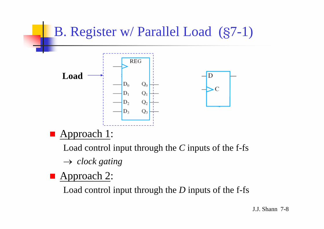
B. Register w/ Parallel Load (§7-1)
Approach 1: Load control input through the C inputs of the f-fs→ clock gating
Approach 2: Load control input through the D inputs of the f-fs
Load

J.J. Shann 7-9
Approach 1: Load control input through the C inputs of the f-fs → clock gating
— prevent the clock from reaching the clock input to the cktif the contents of the reg are to be left unchanged
ClockLoadinputsC +=
* Inserting gates in the clock pulse path produces different propagation delays b/t clock and the inputs of f-fs w/ and w/o clock gating. ⇒ clock skew
J.J. Shann 7-10
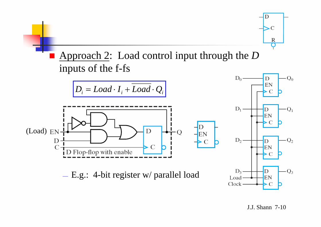
Approach 2: Load control input through the Dinputs of the f-fs
— E.g.: 4-bit register w/ parallel load
iii QLoadILoadD ⋅+⋅=
(Load)
J.J. Shann 7-11
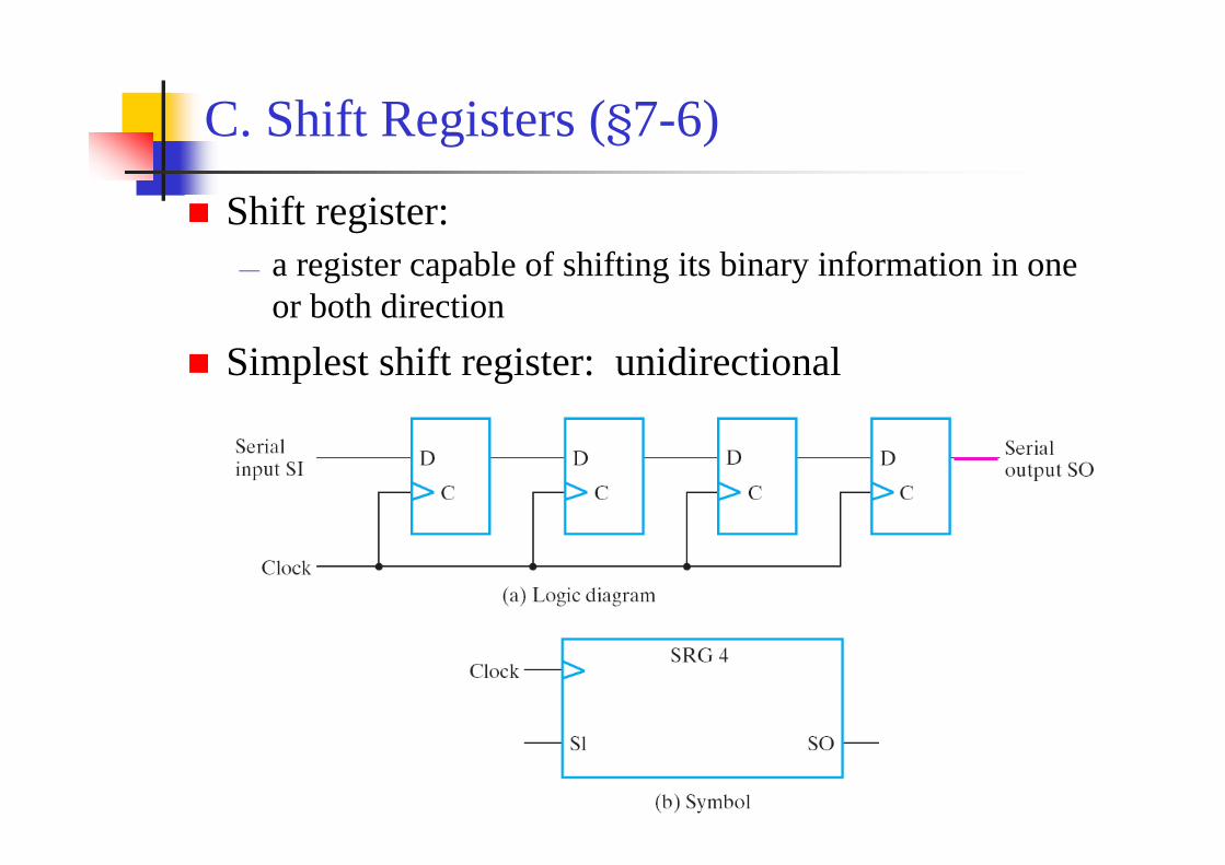
Shift register:— a register capable of shifting its binary information in one
or both direction
Simplest shift register: unidirectional
C. Shift Registers (§7-6)
J.J. Shann 7-12
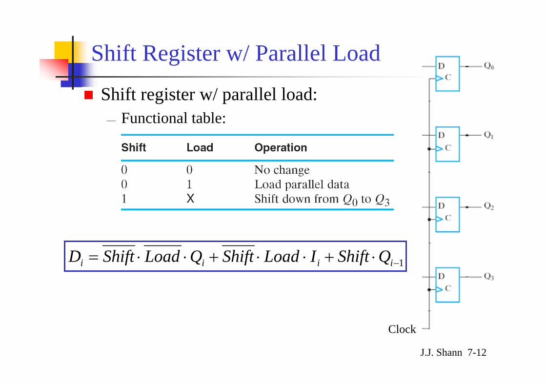
Shift Register w/ Parallel Load
Shift register w/ parallel load:— Functional table:
1−⋅+⋅⋅+⋅⋅= iiii QShiftILoadShiftQLoadShiftD
Clock
J.J. Shann 7-13
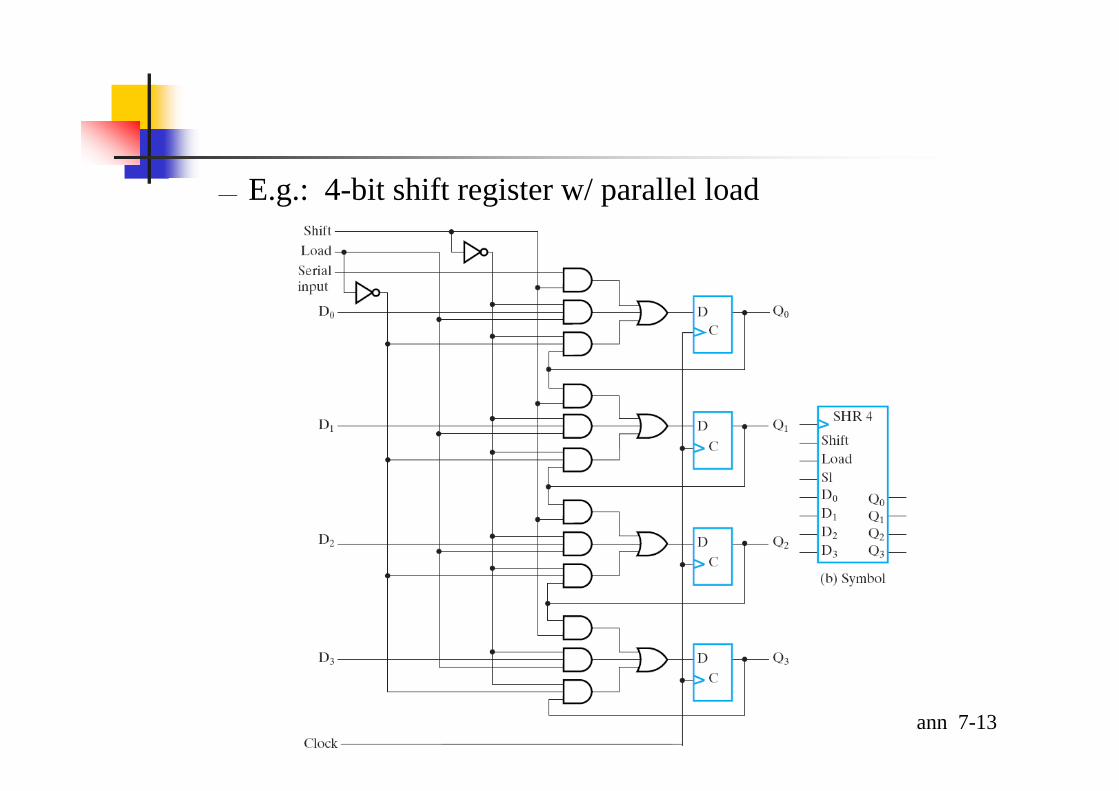
— E.g.: 4-bit shift register w/ parallel load

J.J. Shann 7-14
Bidirectional Shift Register
Bidirectional shift registerdirection = 0 … shl
= 1 … shr
Di = direction • Ai+1 + direction′ • Ai−1
SI of shrSO of shl
SO of shrSI of shl
i i − 1i + 1… …
CLK
directionFlip-Flops
J.J. Shann 7-15
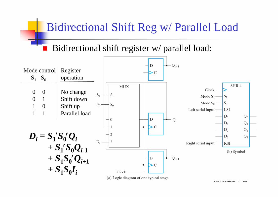
Bidirectional Shift Reg w/ Parallel Load
Bidirectional shift register w/ parallel load:
Mode control RegisterS1 S0 operation
0 0 No change0 1 Shift down1 0 Shift up1 1 Parallel load
Di = S1′S0′Qi+ S1′S0Qi-1+ S1S0′Qi+1+ S1S0Ii
J.J. Shann 7-16
D. Ripple Counters (§7-6)
Counter:— a register that goes through a prescribed sequence of states
upon the application of input pulses:Input pulses:
may be clock pulses or originate from some external source
Timing: may occur at regular or
irregular intervals of timeThe sequence of states:
may follow the binary number sequence (⇒ Binary counter) orany other sequence of states
J.J. Shann 7-17
Categories of counters:1. Ripple counters: (D)
The flip-flop output transition serves as a source for triggering other flip-flops.
⇒ The C input of some or all flip-flops are triggered not by the common clock pulses. (not synchronous)
2. Synchronous counters: (E)The C inputs of all flip-flops receive the common clock.
* T or JK flip-flops
J.J. Shann 7-18
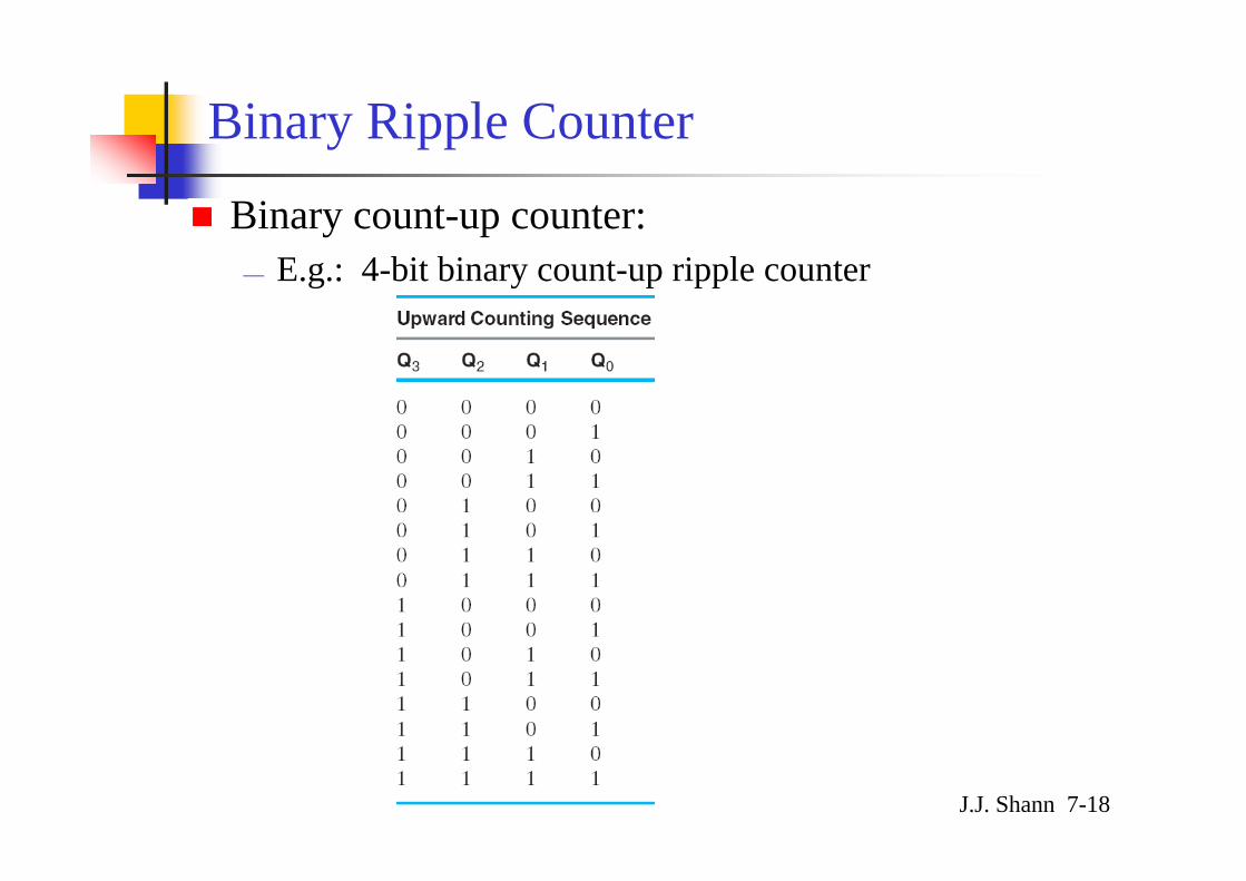
Binary Ripple Counter
Binary count-up counter:— E.g.: 4-bit binary count-up ripple counter
J.J. Shann 7-19
Q0
Q1
Q2
Q3
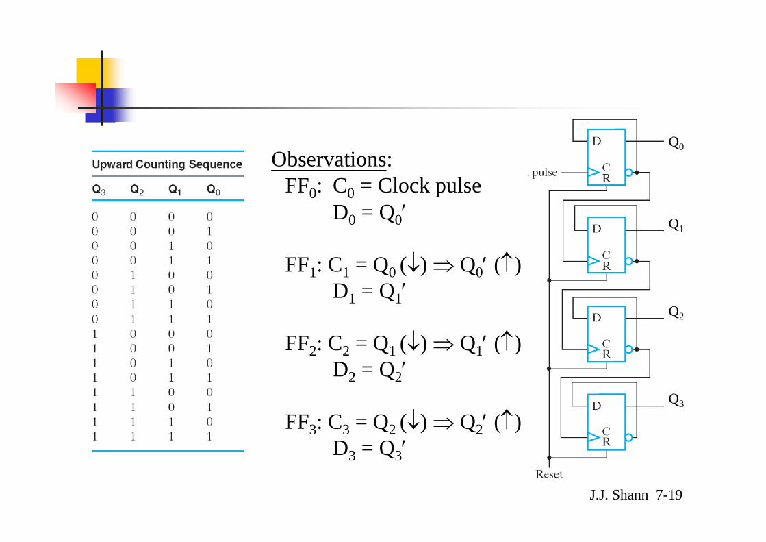
Observations:FF0: C0 = Clock pulse
D0 = Q0′
FF1: C1 = Q0 (↓) ⇒ Q0′ (↑)D1 = Q1′
FF2: C2 = Q1 (↓) ⇒ Q1′ (↑)D2 = Q2′
FF3: C3 = Q2 (↓) ⇒ Q2′ (↑)D3 = Q3′

J.J. Shann 7-20
Q0
Q1
Q2
Q3

J.J. Shann 7-21
* Problem of ripple counter:Accumulation of propagation delay
– E.g.: 2-bit binary count-up ripple counter
Q0
Q1
Q2
Q3
CP
Q1
Q0
0 1 2 3 0 1
J.J. Shann 7-22
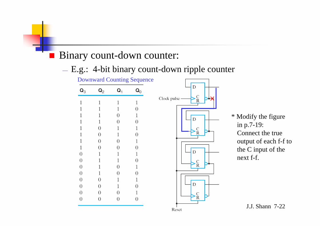
Binary count-down counter:— E.g.: 4-bit binary count-down ripple counter
Downward Counting Sequence
×
* Modify the figure in p.7-19:Connect the true output of each f-f to the C input of the next f-f.

J.J. Shann 7-23
Summary:— are asynchronous ckts— Adv.:
simple hardware
— Disadv.: become ckt w/ delay dependence and unreliable oplarge ripple counters can be slow ckts⇐ the length of time required for the ripple to finish
J.J. Shann 7-24
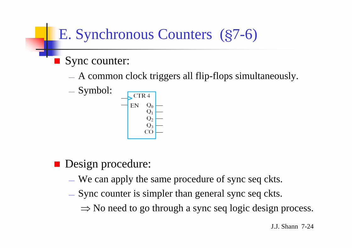
E. Synchronous Counters (§7-6)
Sync counter:— A common clock triggers all flip-flops simultaneously.— Symbol:
Design procedure: — We can apply the same procedure of sync seq ckts.— Sync counter is simpler than general sync seq ckts.
⇒ No need to go through a sync seq logic design process.
J.J. Shann 7-25
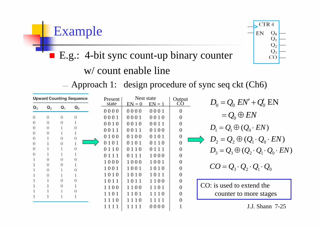
Example
E.g.: 4-bit sync count-up binary counter w/ count enable line
— Approach 1: design procedure of sync seq ckt (Ch6)
CO: is used to extend the counter to more stages
ENQQNEQD
⊕=
′+′=
0
000
EN
)( 011 ENQQD ⋅⊕=
)( 0122 ENQQQD ⋅⋅⊕=)( 01233 ENQQQQD ⋅⋅⋅⊕=
0 0 0 00 0 0 10 0 1 00 0 1 10 1 0 00 1 0 10 1 1 00 1 1 11 0 0 01 0 0 11 0 1 01 0 1 11 1 0 01 1 0 11 1 1 01 1 1 1
0000000000000001
0 0 0 10 0 1 00 0 1 10 1 0 00 1 0 10 1 1 00 1 1 11 0 0 01 0 0 11 0 1 01 0 1 11 1 0 01 1 0 11 1 1 01 1 1 10 0 0 0
0 0 0 00 0 0 10 0 1 00 0 1 10 1 0 00 1 0 10 1 1 00 1 1 11 0 0 01 0 0 11 0 1 01 0 1 11 1 0 01 1 0 11 1 1 01 1 1 1
Presentstate
Nest stateEN = 0 EN = 1
OutputCO
0123 QQQQCO ⋅⋅⋅=

J.J. Shann 7-26
— Approach 2: observation
)( 011 ENQQD ⋅⊕=
)( 0122 ENQQQD ⋅⋅⊕=
)( 01233 ENQQQQD ⋅⋅⋅⊕=
0123 QQQQCO ⋅⋅⋅=
ENQQNEQD
⊕=
′+′=
0
000
EN
J.J. Shann 7-27
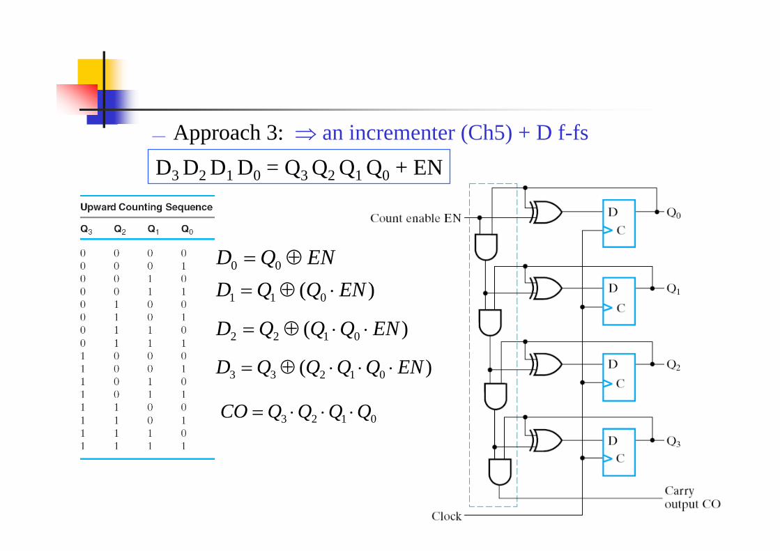
— Approach 3: ⇒ an incrementer (Ch5) + D f-fs
ENQD ⊕= 00
)( 011 ENQQD ⋅⊕=
)( 0122 ENQQQD ⋅⋅⊕=
)( 01233 ENQQQQD ⋅⋅⋅⊕=
0123 QQQQCO ⋅⋅⋅=
D3 D2 D1 D0 = Q3 Q2 Q1 Q0 + EN
J.J. Shann 7-28
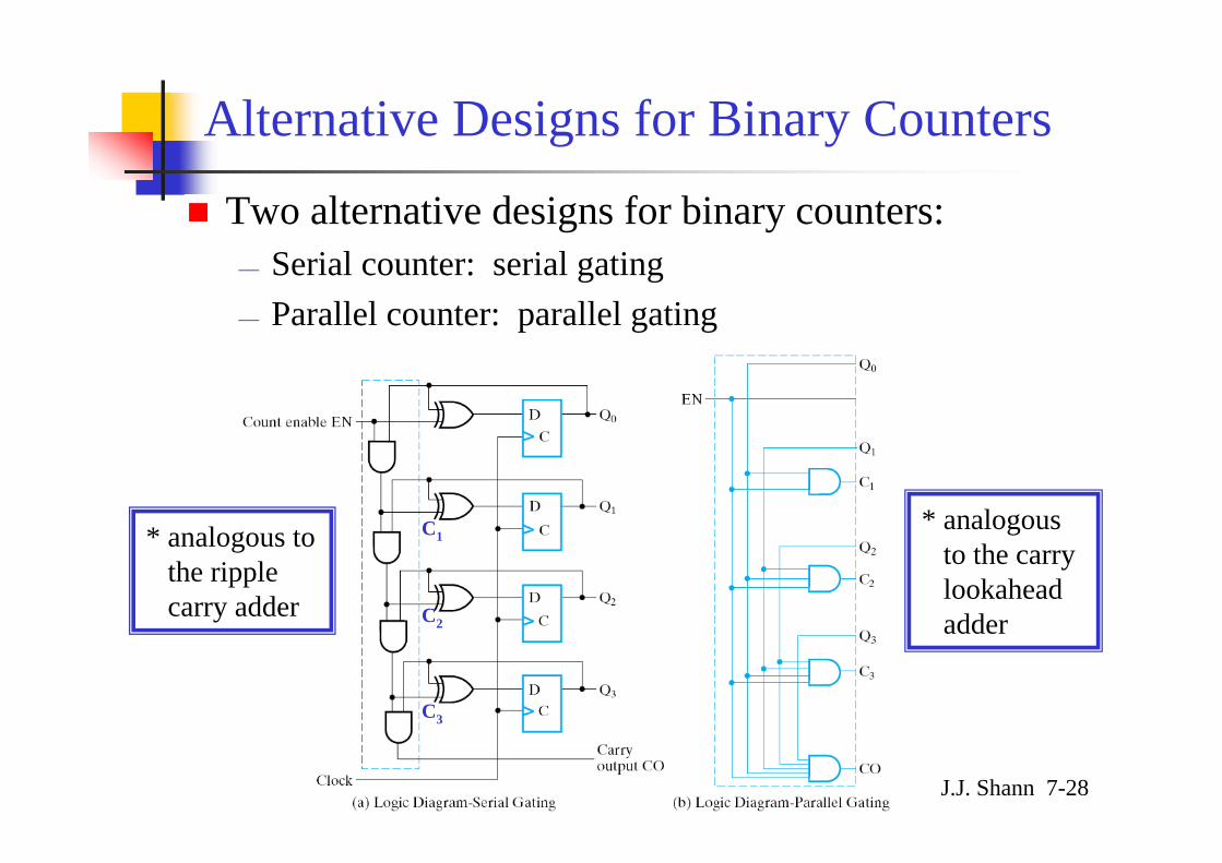
Alternative Designs for Binary Counters
Two alternative designs for binary counters:— Serial counter: serial gating— Parallel counter: parallel gating
* analogous to the carry lookaheadadder
* analogous to the ripple carry adder
C1
C2
C3

J.J. Shann 7-29
Binary Counter by Using JK Flip-Flops
E.g.: 4-bit count-up binary counter w/ JK f-fsBinary count sequence: 3-bit
A2 A1 A0
0 0 00 0 10 1 00 1 11 0 01 0 11 1 01 1 10 0 0

J.J. Shann 7-30
A2 A1 A0
0 0 00 0 10 1 00 1 11 0 01 0 11 1 01 1 10 0 0
J0 = K0 = ENJ1 = K1 = EN • A0
J2 = K2 = EN • A1A0
⇓J3 = K3 = EN • A2A1A0
J.J. Shann 7-31
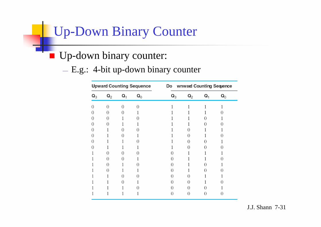
Up-Down Binary Counter
Up-down binary counter:— E.g.: 4-bit up-down binary counter
J.J. Shann 7-32
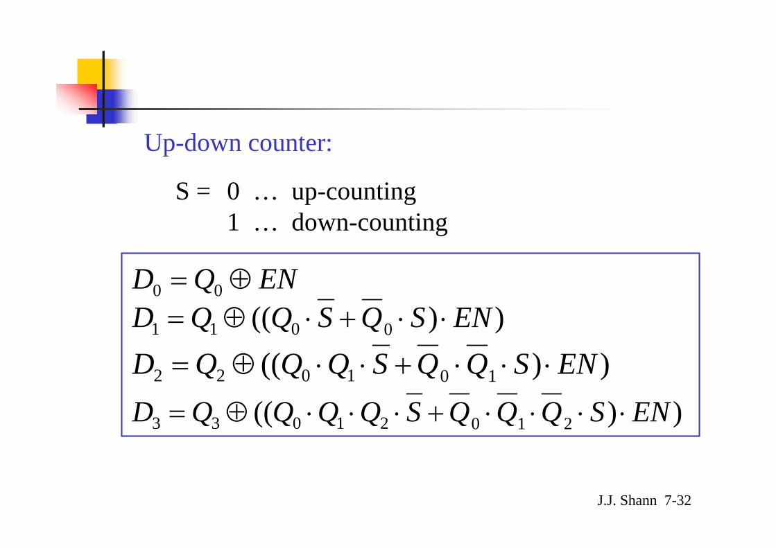
ENQD ⊕= 00
))(( 0011 ENSQSQQD ⋅⋅+⋅⊕=
))(( 101022 ENSQQSQQQD ⋅⋅⋅+⋅⋅⊕=
))(( 21021033 ENSQQQSQQQQD ⋅⋅⋅⋅+⋅⋅⋅⊕=
S = 0 … up-counting1 … down-counting
Up-down counter:
J.J. Shann 7-33
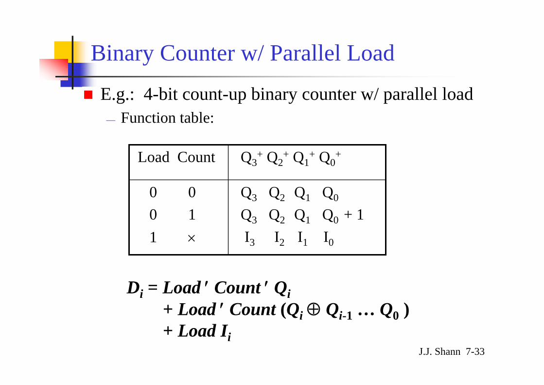
E.g.: 4-bit count-up binary counter w/ parallel load— Function table:
Binary Counter w/ Parallel Load
Q3 Q2 Q1 Q0
Q3 Q2 Q1 Q0 + 1I3 I2 I1 I0
0 00 11 ×
Q3+ Q2
+ Q1+ Q0
+Load Count
Di = Load ′ Count ′ Qi+ Load ′ Count (Qi ⊕ Qi-1 … Q0 ) + Load Ii
J.J. Shann 7-34
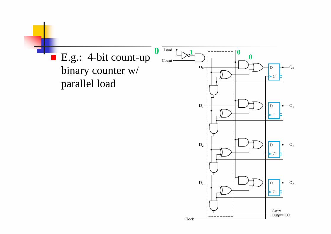
E.g.: 4-bit count-up binary counter w/ parallel load
0 010
J.J. Shann 7-35
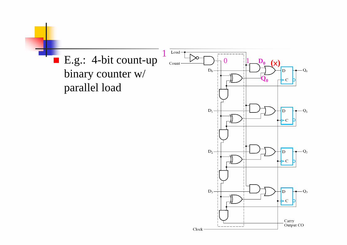
E.g.: 4-bit count-up binary counter w/ parallel load
110 D0
Q0
(×)

J.J. Shann 7-36
Generating Other Count Sequences
Generate any count sequence:— E.g.: design a BCD counter by using a counter w/ parallel
load & async clear

J.J. Shann 7-37

J.J. Shann 7-38
F. Other Counters (§7-6)
Counters:— can be designed to generate any desired sequence of states
Binary counter (D, E)BCD counterDivide-by-N counter: modulo-N counter
— a counter that goes through a repeated sequence of Nstates
— The sequence may follow the binary count or may be any other arbitrary sequence.

J.J. Shann 7-39
BCD Counter
State diagram & Count sequence: Q8 Q4 Q2 Q1
0 0 0 00 0 0 10 0 1 00 0 1 10 1 0 00 1 0 10 1 1 00 1 1 11 0 0 01 0 0 10 0 0 0
J.J. Shann 7-40
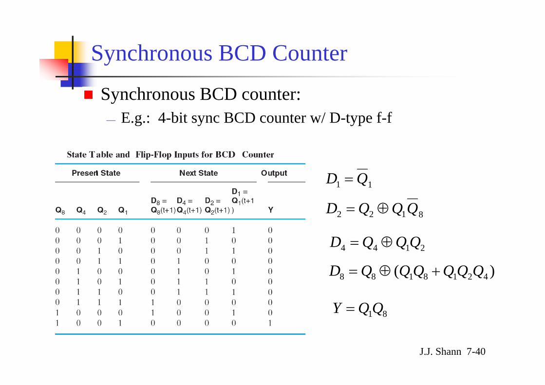
Synchronous BCD Counter
Synchronous BCD counter:— E.g.: 4-bit sync BCD counter w/ D-type f-f
11 QD =
8122 QQQD ⊕=
2144 QQQD ⊕=
)( 4218188 QQQQQQD +⊕=
81QQY =
J.J. Shann 7-41
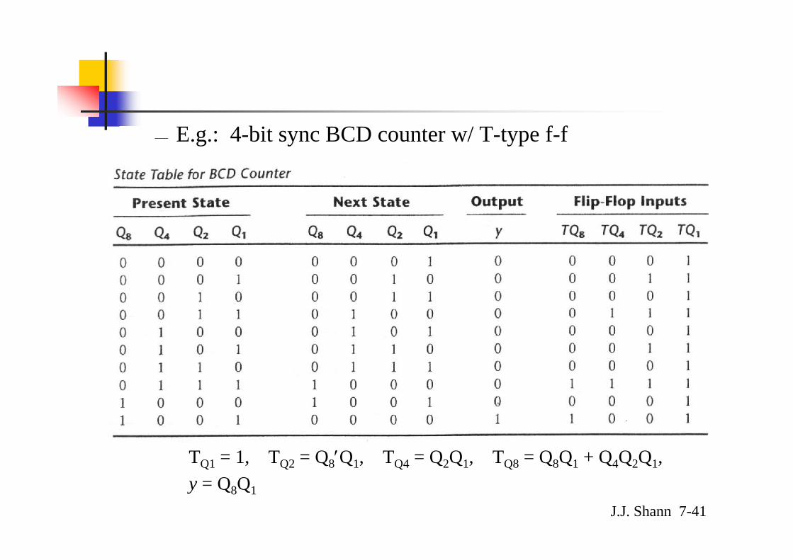
— E.g.: 4-bit sync BCD counter w/ T-type f-f
TQ1 = 1, TQ2 = Q8′Q1, TQ4 = Q2Q1, TQ8 = Q8Q1 + Q4Q2Q1, y = Q8Q1

J.J. Shann 7-42
Three-decade BCD counter:

J.J. Shann 7-43
Counter w/ Unused States
n flip-flops ⇒ 2n binary statesUnused states:
— states that are not used in specifying the sequential ckt— may be treated as don’t-care conditions or
may be assigned specific next states
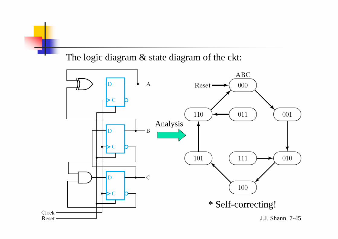
Self-correcting counter:— Ensure that when a ckt enter one of its unused states, it
eventually goes into one of the valid states after one or more clock pulses so it can resume normal operation.⇒ Analyze the ckt to determine the next state from an
unused state after it is designed.
J.J. Shann 7-44
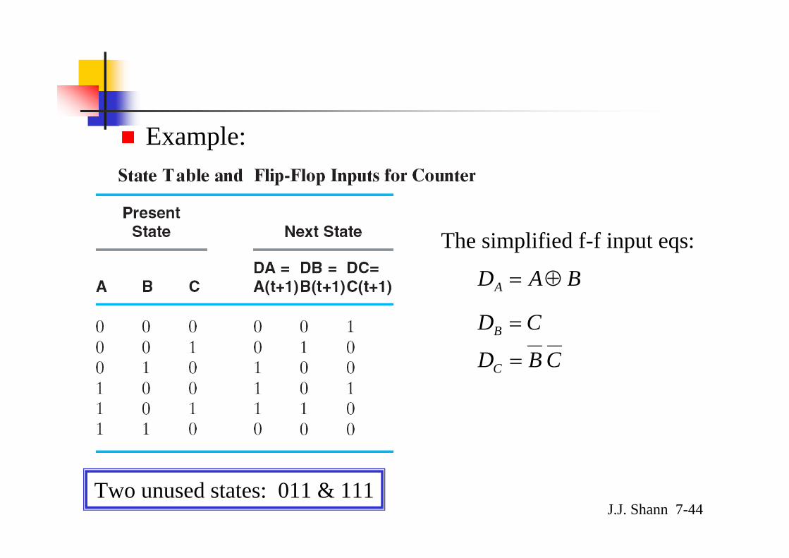
Example:
Two unused states: 011 & 111
BADA ⊕=
CDB =
CBDC =
The simplified f-f input eqs:
J.J. Shann 7-45
The logic diagram & state diagram of the ckt:
* Self-correcting!
Analysis
J.J. Shann 7-46
7-12 Chapter Summary
Registers— Simplest register (§7-1)— Register with parallel load (§7-1)— Shift registers (§7-6)
Counters— Ripple counter (§7-6)— Synchronous binary counters (§7-6)— Other counters (§7-6)