Embed Size (px)
Citation preview

Chapter 74:
Biopotentials and Electrophysiology Measurement
Teemu Rämö
butler.cc.tut.fi/~malmivuo/bem/bembook/
Agenda
• 1st half• Introduction to biopotentials
• Measurement methods• Traditional: ECG, EEG, EMG, EOG
• Novell: VCG
• 2nd half• Measurement considerations
• Electronics
• Electrodes
• Practices
• Q&A

What are biopotentials
Biopotential: An electric potential that is measured between points in living cells, tissues, and organisms, and which accompanies all biochemical processes.
• Also describes the transfer of information between and within cells
• This book focuses strictly on the measurement of potentials

Mechanism behind biopotentials 1/2
• Concentration of potassium (K+) ions is 30-50 times higher inside as compared to outside
• Sodium ion (Na+) concentration is 10 times higher outside the membrane than inside
• In resting state the member is permeable only for potassium ions
Potassium flows outwards leaving an equal number of negative ions inside
Electrostatic attraction pulls potassium and chloride ions close to the membrane
Electric field directed inward formsElectrostatic force vs. diffusional force
• Nernst equation:
• Goldman-Hodgkin-Katz equation:
mVVm 100...70
ko
ki
kk c
c
Fz
RTV
,
,ln
CliClNaiNaKiK
CliClNaiNaKiK
km cPcPcP
cPcPcP
Fz
RTV
,,,
,,,ln
mVVm 100...70

Mechanism behind biopotentials 2/2• When membrane stimulation exceeds a
threshold level of about 20 mV, so called action potential occurs:1. Sodium and potassium ionic permeabilities of
the membrane change2. Sodium ion permeability increases very rapidly
at first, allowing sodium ions to flow from outside to inside, making the inside more positive
3. The more slowly increasing potassium ion permeability allows potassium ions to flow from inside to outside, thus returning membrane potential to its resting value
4. While at rest, the Na-K pump restores the ion concentrations to their original values
• The number of ions flowing through an open channel >106/sec
• Body is an inhomogeneous volume conductor and these ion fluxes create measurable potentials on body surface

Electrocardiography (ECG)
• Measures galvanically the electric activity of the heart
• Well known and traditional, first measurements byAugustus Waller using capillary electrometer (year 1887)
• Very widely used method in clinical environment
• Very high diagnostic value
1. Atrial depolarization
2. Ventriculardepolarization
3. Ventricular repolarization

ECG basics
• Amplitude: 1-5 mV
• Bandwidth: 0.05-100 Hz
• Largest measurement error sources:• Motion artifacts
• 50/60 Hz powerline interference
• Typical applications:• Diagnosis of ischemia
• Arrhythmia
• Conduction defects
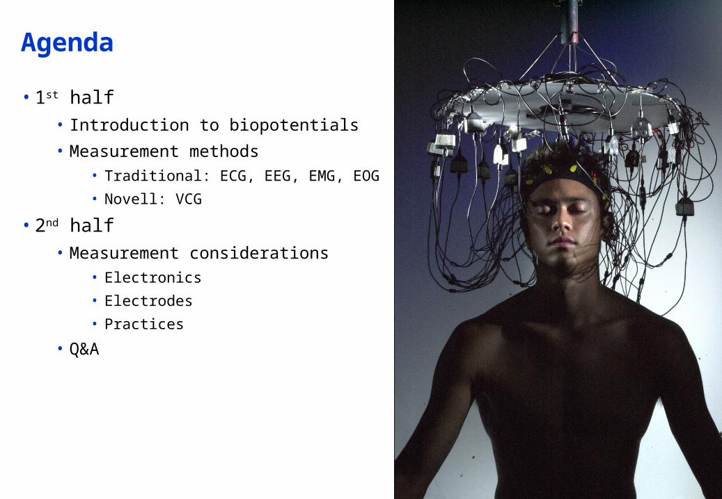
12-Lead ECG measurement
• Most widely used ECG measurement setup in clinical environment
• Signal is measured non-invasively with 9 electrodes
• Lots of measurement data and international reference databases
• Well-known measurement and diagnosis practices
• This particular method was adopted due to historical reasons, now it is already rather obsolete
Einthoven leads: I, II & III Goldberger augmented leads: VR, VL & VF Precordial leads: V1-V6

Why is 12-lead system obsolete?
• Over 90% of the heart’s electric activity can be explained with a dipole source model
Only 3 orthogonal components need to be measured, which makes 9 of the leads redundant
• The remaining percentage, i.e. nondipolar components, may have some clinical value
This makes 8 truly independent and 4 redundant leads
• 12-lead system does, to some extend, enhance pattern recognition and gives the clinician a few more projections to choose from
…but….
• If there was no legacy problem with current systems, 12-lead system would’ve been discarded ages ago

Electroencephalography (EEG)
• Measures the brain’s electric activity from the scalp
• Measured signal results from the activity of billions of neurons
• Amplitude: 0.001-0.01 mV• Bandwidth: 0.5-40 Hz
• Errors:• Thermal RF noise• 50/60 Hz power lines• Blink artifacts and similar
• Typical applications:• Sleep studies• Seizure detection• Cortical mapping

EEG measurement setup
• 10-20 Lead system is most widely clinically accepted
• Certain physiological featuresare used as reference points
• Allow localization of diagnostic features in the vicinity of the electrode
• Often a readily available wire or rubber mesh is used
• Brain research utilizes even 256 or 512 channel EEG hats

Electromyography (EMG)
• Measures the electric activity of active muscle fibers
• Electrodes are always connected very close to the muscle group being measured
• Rectified and integrated EMG signal gives rough indication of the muscle activity
• Needle electrodes can be used to measure individual muscle fibers
• Amplitude: 1-10 mV
• Bandwidth: 20-2000 Hz
• Main sources of errors are 50/60 Hz and RF interference
• Applications: muscle function, neuromuscular disease, prosthesis

Electrooculography (EOG)
• Electric potentials are created as a result of the movement of the eyeballs
• Potential varies in proportion to the amplitude of the movement
• In many ways a challenging measurement with some clinical value
• Amplitude: 0.01-0.1 mV
• Bandwidth: DC-10 Hz
• Primary sources of error include skin potential and motion
• Applications: eye position, sleep state, vestibulo-ocular reflex
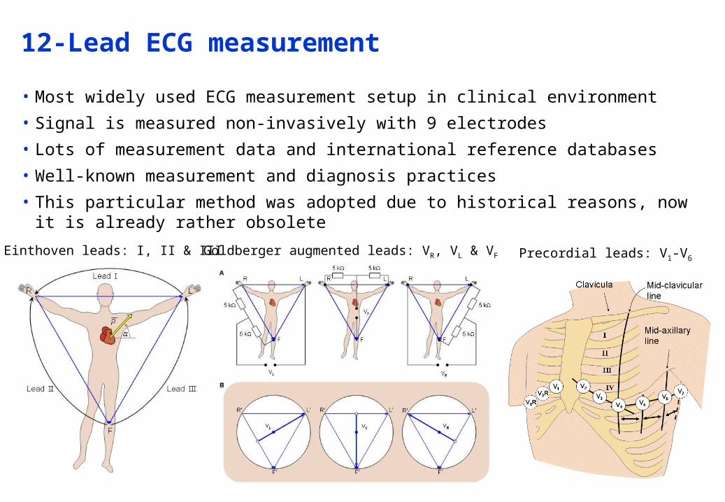
Vectorcardiogram (VCG or EVCG)
• Instead of displaying the scalar amplitude (ECG curve) the electric activation front is measured and displayed as a vector (dipole model, remember?)
It has amplitude and direction
• Diagnosis is based on the curve that the point of this vector draws in 2 or 3 dimensions
• The information content of the VCG signal is roughly the same as 12-lead ECG system. The advantage comes from the way how this information is displayed
• A normal, scalar ECG curve can be formed from this vectro representation, although (for practical reasons) transformation can be quite complicated
• Plenty of different types of VCG systems are in use
No legacy problem as such

Short break,
Kahvia ja pullaa!

The biopotential amplifier
• Small amplitudes, low frequencies, environmental and biological sources of interference etc.
• Essential requirements for measurement equipment:• High amplification
• High differential gain, low common mode gain high CMRR
• High input impedance
• Low Noise
• Stability against temperature and voltage fluctuations
• Electrical safety, isolation and defibrillation protection
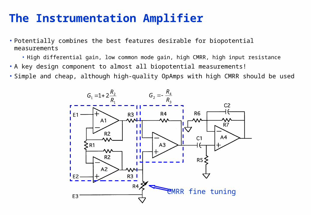
The Instrumentation Amplifier
• Potentially combines the best features desirable for biopotential measurements• High differential gain, low common mode gain, high CMRR, high input resistance
• A key design component to almost all biopotential measurements!
• Simple and cheap, although high-quality OpAmps with high CMRR should be used
1
21 21
R
RG
3
42 R
RG
CMRR fine tuning
Application-specific requirements
• ECG amplifier• Lower corner frequency 0.05 Hz, upper 100Hz
• Safety and protection: leakage current below safety standard limit of 10 uA
• Electrical isolation from the power line and the earth ground
• Protection against high defibrillation voltages
• EEG amplifier• Gain must deal with microvolt or lower levels of signals
• Components must have low thermal and electronic noise @ the front end
• Otherwise similar to ECG
• EMG amplifier• Slightly enhanced amplifier BW suffices
• Post-processing circuits are almost always needed (e.g. rectifier + integrator)
• EOG amplifier• High gain with very good low frequency (or even DC) response
• DC-drifting electrodes should be selected with great care
• Often active DC or drift cancellation or correction circuit may be necessary

Electrical Interference Reduction
• Power line interference (50 or 60 Hz) is always around us• Connects capacitively and causes common mode interference• The common mode interference would be completely rejected by the
instrumentation amplifier if the matching would be ideal• Often a clever “driven right leg circuit” is used to further enhance CMRR
Average of the VCM is inverted and driven back to the body via reference electrode
0RiV DCM
1
2
0
21RRRi
V DCM

Filtering• Filtering should be included in the front end of the InstrAmp
• Transmitters, motors etc. cause also RF interference
Small inductorsor ferrite beadsin the lead wires
block HF frequencyEM interference
RF filtering withsmall capacitors
High-pass filterto reject DC drifting
Low-pass filteringat several stages
is recommended toattenuate residual
RF interference

50 or 60 Hz notch filter
• Sometimes it may be desirable to remove the power line interference
• Overlaps with the measurement bandwidthMay distort the measurement result and have an affect on the diagnosis!
• Option often available with EEG & EOG measuring instruments
Twin Tnotch filter
Determinesnotch
frequency
Notchtuning

Artifact reduction
• Electrode-skin interface is a major source of artifact• Changes in the junction potential causes slow changes in the baseline
• Movement artifacts cause more sudden changes and artifacts
• Drifting in the baseline can be detected by discharging the high-pass capacitor in the amplifier to restore the baseline

Electrical isolation
• Electrical isolation limits the possibility of passage of any leakage current from the instrument in use to the patient
• Such passage would be harmful if not fatal!
1. Transformer• Transformers are inherently high
frequency AC devices
• Modulation and demodulation needed
2. Optical isolation• Optical signal is modulated in
proportion to the electric signal and transmitted to the detector
• Typically pulse code modulated to circumvent the inherent nonlinearity of the LED-phototransistor combination

Defibrillation Protection
• Measuring instruments can encounter very high voltages
• E.g. 1500…5000V shocks from defibrillator
• Front-end must be designed to withstand these high voltages
1. Resistors in the inputleads limit the current
3. Protection against much higher voltages
is achieved withlow-pressure gasdischarge tubes
(e.g. neon lamps)
(note: even isolationcomponents such as
transformers andoptical isolators need
these spark gaps)Discharge @ ~100V
2. Diodes or Zener diodesprotect against high
voltages
Discharge @ 0.7-15V

Electrodes – Basics
• High-quality biopotential measurements require• Good amplifier design• Use of good electrodes and their proper placement on the patient• Good laboratory and clinical practices
• Electrodes should be chosen according to the application• Basic electrode structure includes:
• The body and casing• Electrode made of high-conductivity material• Wire connector• Cavity or similar for electrolytic gel• Adhesive rim
• The complexity of electrode design often neglected

Electrodes - Basics
• Skin preparation by abrasion or cleansing
• Placement close to the source being measured
• Placement above bony structures where there is less muscle mass
• Distinguishing features of different electrodes:• How secure? The structure and the use of strong but less irritant adhesives
• How conductive? Use of noble metals vs. cheaper materials
• How prone to artifact? Use of low-junction-potential materials such as Ag-AgCl
• If electrolytic gel is used, how is it applied? High conductivity gels can help reduce the junction potentials and resistance but tend to be more allergenic or irritating
Baseline drift due to thechanges in junction
potential or motion artifactsChoice of electrodes Muscle signal
interference Placement
Electromagneticinterference Shielding

Ag-AgCl, Silver-Silver Chloride Electrodes
• The most commonly used electrode type
• Silver is interfaced with its salt silver-chloride
• Choice of materials helps to reduce junction potentials• Junction potentials are the result of the dissimilar
electrolytic interfaces
• Electrolytic gel enhances conductivity and also reduces junction potentials
• Typically based on sodium or potassium chloride, concentration in the order of 0.1 M weak enough to not irritate the skin
• The gel is typically soaked into a foam pad or applied directly in a pocket produced by electrode housing
• Relatively low-cost and general purpose electrode
• Particularly suited for ambulatory or long term use
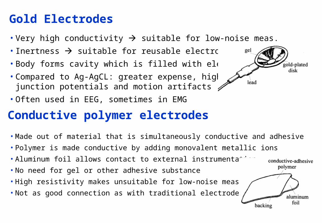
Gold Electrodes
• Very high conductivity suitable for low-noise meas.
• Inertness suitable for reusable electrodes
• Body forms cavity which is filled with electrolytic gel
• Compared to Ag-AgCL: greater expense, higherjunction potentials and motion artifacts
• Often used in EEG, sometimes in EMG
Conductive polymer electrodes
• Made out of material that is simultaneously conductive and adhesive
• Polymer is made conductive by adding monovalent metallic ions
• Aluminum foil allows contact to external instrumentation
• No need for gel or other adhesive substance
• High resistivity makes unsuitable for low-noise meas.
• Not as good connection as with traditional electrodes
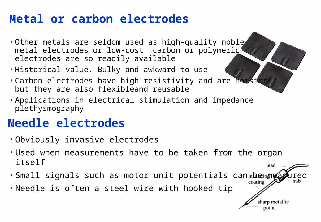
Metal or carbon electrodes
• Other metals are seldom used as high-quality noblemetal electrodes or low-cost carbon or polymericelectrodes are so readily available
• Historical value. Bulky and awkward to use• Carbon electrodes have high resistivity and are noisier
but they are also flexibleand reusable• Applications in electrical stimulation and impedance plethysmography
Needle electrodes• Obviously invasive electrodes
• Used when measurements have to be taken from the organ itself
• Small signals such as motor unit potentials can be measured
• Needle is often a steel wire with hooked tip

That’s it,
Now for Q&A
SQUID = Superconducting Quantum Interference Device