Embed Size (px)
Citation preview

1
Chapter 7
Transmission Media

2
Guided and Unguided Transmission • How should transmission media be
divided into classes? • There are two broad approaches:
– By type of path: communication can follow an exact path such as a wire, or can have no specific path, such as a radio transmission
– By form of energy: electrical energy is used on wires, radio transmission is used for wireless, and light is used for optical fiber
• We use the terms guided (wired) and unguided (wireless) transmission to distinguish between physical media

3
Background Radiation and Electrical Noise
• Electrical current flows along a complete circuit – all transmissions of electrical energy need two wires to form a circuit; a wire
to the receiver and a wire back to the sender • The simplest form of wiring consists of a cable that contains two copper
wires • Important facts:
1. Random electromagnetic radiation, called noise, permeates the environment – In fact, communication systems generate minor amounts of
electrical noise as a side-effect of normal operation 2. When it hits metal, electromagnetic radiation induces a small signal
– random noise can interfere with signals used for communication
3. Because it absorbs radiation, metal acts as a shield

4
Twisted Pair Copper Wiring
• There are three forms of wiring that help reduce interference from electrical noise – Unshielded Twisted Pair (UTP)
• also known as twisted pair wiring – Coaxial Cable – Shielded Twisted Pair (STP)
• Twisting two wires makes them less susceptible to electrical noise than leaving them parallel
plastic outer coating
woven or braided metal
insulating material
copper wire
twisted-pair cable twisted-pair wire

Twisted Pair Copper Wiring
5
Current is balanced à EMR impact is reduced!
each of the two wires is on top one-half of the time, which means each wire absorbs the same amount of radiation

6
Shielding: Coaxial Cable and Shielded Twisted Pair
• Using braided wire instead of a solid metal shield keeps coaxial cable flexible – but the heavy shield does make coaxial cable less flexible than
twisted pair wiring
• Variations of shielding have been invented that provide a compromise – the cable is more flexible, but has slightly less immunity to electrical
noise
• One popular variation is known as shielded twisted pair (STP) – The cable has a thinner, more flexible metal shield surrounding one
or more twisted pairs of wires – In most versions of STP cable, the shield consists of metal foil,
similar to the aluminum foil used in a kitchen

Shielding: Coaxial Cable and Shielded Twisted Pair
7
Better Shielding à More Expensive

Categories of Twisted Pair Cable
8
http://searchdatacenter.techtarget.com/sDefinition/0,,sid80_gci211752,00.html
Higher
9
http://searchdatacenter.techtarget.com/sDefinition/0,,sid80_gci211752,00.html

Categories of Twisted Pair Cable – Some notes • CAT 5 and CAT 5E UTP cables can support 10/100/1000
Mbps Ethernet. – Although Cat 5 cable may support to some degree in Gigabit
Ethernet (1000 Mbps), it performs below standard during high-data transfer scenarios,
• CAT 6 UTP cable is manufactured targeting on Gigabit Ethernet and backward compatible with 10/100 Mbps Ethernet.
10

11
Media Using Light Energy and Optical Fibers • Three forms of media use light energy to carry information:
– Optical fibers (most common) – InfraRed transmission – Point-to-point lasers

12
Media Using Light Energy and Optical Fibers
• Reflection in an optical fiber is not perfect – Reflection absorbs a small amount of energy – If a photon takes a zig-zag path that reflects from the walls of the
fiber many times • the photon will travel a slightly longer distance than a photon that takes a
straight path
– The result is that a pulse of light sent at one end of a fiber emerges with less energy and is dispersed (i.e., stretched) over time
– Dispersion is a serious problem for long optical fibers

13
Types of Fiber and Light Transmission • Single mode fiber and the equipment used at each end are designed to
focus light – A pulse of light can travel long distances without becoming dispersed – Minimal dispersion helps increase the rate at which bits can be sent
• because a pulse corresponding to one bit does not disperse into the pulse that corresponds to a successive bit
• How is light sent and received on a fiber? – The key is that the devices used for transmission must match the fiber
• Two transmission technologies: LED or Injection Laser Diode (ILD) • Reception: photo-sensitive cell or photodiode
– LEDs and photo-sensitive cells are used for short distances and slower bit rates common with multimode fiber;
– single mode fiber, used over long distance with high bit rates, generally requires ILDs and photodiodes
Project

14
Infrared (IR) Communication Technologies
• IR uses the same type of energy as a TV remote control: – a form of electromagnetic radiation that behaves like visible light but
falls outside the range that is visible to a human eye • Like visible light, infrared disperses quickly • Infrared signals can reflect from a smooth, hard surface • An opaque object (not letting light pass through) as thin as a
sheet of paper can block the signal – moisture in the atmosphere
• IR commonly used to connect to a nearby peripheral • Many different technologies:
– The Infrared Data Association (IrDA) – IrDA is a very short-range
Project

Point-to-Point Laser Communication
• A pair of devices with a beam that follows the line-of-sight • IR is classified as providing point-to-point communication • Other point-to-point communication technologies also exist
– One form of point-to-point communication uses a beam of coherent light produced by a laser
• Laser communication follows line-of-sight, and requires a clear, unobstructed path between the communicating sites – Unlike an infrared transmitter, however, a laser beam does not cover
a broad area; the beam is only a few centimeters wide – The sending and receiving equipment must be aligned precisely to
insure that the sender's beam hits the sensor in the receiver – They are suitable for use outdoors, and can span great distances – As a result, laser technology is especially useful in cities to transmit
from building to building

Electromagnetic (Radio) Communication
• Skip this section up to 7-19.

Tradeoffs Among Media Types
• The choice of medium is complex • Choice involves the evaluation of multiple factors, such as:
– Cost • materials, installation, operation, and maintenance
– Data rate • number of bits per second that can be sent
– Delay • time required for signal propagation or processing
– Affect on signal • attenuation and distortion
– Environment • susceptibility to interference and electrical noise
– Security • susceptibility to eavesdropping

Channel Capacity • Defined as how fast the data (in bits) can be communicated • Many factors impact channel capacity
– Data rate – Bandwidth – Noise – Error rate
• What is the relation between these factors?
18

Nyquist Formula and Bandwidth
• Assuming noise free system and assuming that only one bit is provided to represent the signal:
• Nyquist’s formula states the limitation of the data rate due to the bandwidth:
– If the signal transmission rate is 2B (bps), then a signal with frequency of less or equal B (Hz) is required to carry this signal: TR(f)=2Bàf≤B
– If bandwidth is B (Hz)à the highest signal rate that can be carried is 2B (bps): f=BàTR(f)≤2B
• Example: if the highest frequency is 4KHz (bandwidth) a sampling rate of 8 Kbps is required to carry the signal
• Note: data rate in bps= (number of bit per symbol) x (modulation rate in baud)

Channel Capacity Nyquist’s formulation when multilevel signaling is present
• channel capacity (C) is the tightest upper bound on the amount of information that can be reliably transmitted over a communications channel (max. allowable data rate)
• What if the number of signal levels are more than 2 (we use more than a single bit to represent the sate of the signal)?
C B MMmeberM M
n
=
=
=
22
2
2
2
log ( )
Re :log ( ) ln( ) / ln( )
o C = Maximum theoretical Channel Capacity in bps
o M = number of discrete signals (symbols) or voltage levels
o n = number of bits per symbol
Remember: More bits per symbol à more complexity!
Example: Log2(8)=ln(8)/ln(2)=3
Channel Capacity Example: • Voice has a BW of 3100 Hz. calculate the maximum channel
capacity – Assuming we use 2 signal levels – Assuming we use 8 signal levels

Channel Capacity Example: • Voice has a BW of 3100 Hz. calculate the maximum channel
capacity – Assuming we use 2 signal levels – Assuming we use 8 signal levels
• à channel capacity required to pass a voice signal: • Max. Channel capacity (or Nyquist capacity) is 2 x 3100
cycles/sec = 6.1Kbps – note in this case one bit is being used to represent two distinct signal levels.
• If we use 8 signal levels: channel capacity: 2x3100x3=18600 bps à higher capacity!
:Data rate is how fast we are communicating BW is constrained by the medium and the system property
So, in real world, how much can Channel Cap.
Be increased by?

S/N Ratio
• The signal and noise powers S and N are measured in
watts or volts^2, so the signal-to-noise ratio here is expressed as a power ratio, not in decibels (dB)
SNRSignalPower watt VoltNoisePower watt Volt
meber
y y xPower dB Pout PinPower dBm P mW mW
dB
x
=
= ⎯ →⎯⎯ =
=
=
10
101010 1
10
2
2
10
10
10
log( / )( / )
Re :
log( ) log ( / )( ) log ( ( ) / )
Example: Assume signal strength is 2 dBm and noise strength is 5 mW. Calculate the SNR in dB.
2dBmà 1.59 mW SNR = 10log(1.59/5)=-5dB

Channel Capacity with Noise and Error
• An application of the channel capacity concept to an additive white Gaussian noise channel with B Hz bandwidth and signal-to-noise ratio S/N is the Shannon–Hartley theorem:
• Establishing a relation between error rate, noise, signal strength, and BW
• If the signal strength or BW increases, in the presence of noise, we can increase the channel capacity
• Establishes the upper bound on achievable data rate (theoretical) – Does not take into account impulse and attenuation
Note: S/N is not in dB and it is
log base 2!

Noise Impact on Channel Capacity
• Presence of noise can corrupt the signal • Unwanted noise can cause more damage to signals at
higher rate • For a given noise level, greater signal strength
improves the ability to send signal – Higher signal strength increases system nonlinearity à more
intermodulation noise – Also wider BW à more thermal noise into the system à
increasing B can result in lower SNR

Example of Nyquist Formula and Shannon–Hartley Theorem
• Calculate the BW of this signal. • Assuming the SNR = 24 dB, Calculate the
maximum channel capacity. • Using the value of the channel capacity,
calculate how many signal levels are required to generate this signal?
• How many bits are required to send each signal level?
• Express the mathematical expression of this signal in time domain.
3MHz 4MHz
B=4-3=1 MHz
SNRdB(24)àlog-1(24/10) 102.4= 251
C=Blog2(1+S/N)=8Mbps C=2Blog2MàM=16
2n=Màn=4
π/4
π/3x4
http://www.adec.edu/tag/spectrum.html

Channel Capacity Example: • Voice has a BW of 3100 Hz. Assume SNR =24 dB. calculate
the maximum channel capacity – Assuming we use 8 signal levels
SNRdB(24)àlog-1(24/10) 102.4= 251
C=Blog2(1+S/N) 3100.8=24,800 bps

Signal Impairments Attenuation
• Strength of a signal falls off with distance over transmission medium
• Attenuation factors for guided media: – Received signal must have sufficient
strength so that circuitry in the receiver can interpret the signal
– Signal must maintain a level sufficiently higher than noise to be received without error
– Typically signal strength is reduced exponentially
– Expressed in dB
Attenuation is greater at higher frequencies, causing distortion
Attenuation dBd
Attenuation dBd
Wherewavelength d dis ce
( ) log ( )
( ) log ( )
:; tan
=
=
= =
104
204
102
10
πλπλ
λ

Signal Impairments Attenuation Impacts
• Lowers signal strength • Requires higher SNR • Can change as a function of
frequency – More of a problem in analog
signal (less in digital) – Higher frequencies attenuate
faster – Using equalization can
improve – higher frequencies have stronger strength

Signal Impairments Delay Distortion
• In bandlimited signals propagation velocity is different for different frequencies – Highest near the center frequency – Hence, bits arrive out of sequence – à resulting in intersymbol interference – àlimiting the maximum bit rate!

Categories of Noise • Thermal Noise • Intermodulation noise • Crosstalk • Impulse Noise

Thermal Noise
• Thermal noise due to agitation of electrons • Present in all electronic devices and transmission media • Cannot be eliminated • Function of temperature • Particularly significant for satellite communication
– When the signal that is received is very weak

Thermal Noise • Amount of thermal noise to be found in a bandwidth of
1Hz in any device or conductor is:
• N0 = noise power density in watts per 1 Hz of bandwidth • k = Boltzmann's constant = 1.3803 × 10⁻²³ J/K • T = temperature, in Kelvins (absolute temperature) – zero
deg. C is 273.15 • Expressed in dBW 10log(No/1W)
( )W/Hz k0 TN =

Thermal Noise
• Noise is assumed to be independent of frequency • Thermal noise present in a bandwidth of B Hertz (in watts):
or, in decibel-watts
TBN k=
BTN log10 log 10k log10 ++=
( )W/Hz k0 TN = à
k = Boltzmann's constant = 1.3803 × 10⁻²³ J/K
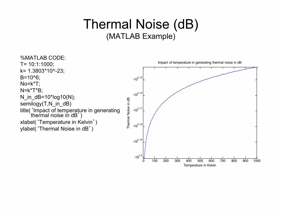
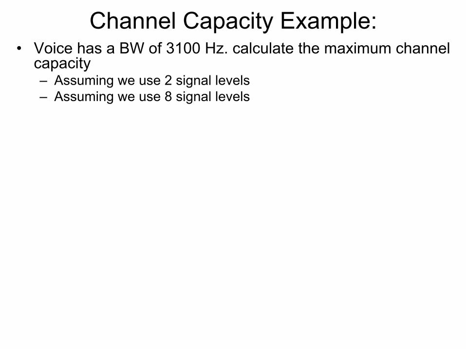
Thermal Noise (dB) (MATLAB Example)
%MATLAB CODE: T= 10:1:1000; k= 1.3803*10^-23; B=10^6; No=k*T; N=k*T*B; N_in_dB=10*log10(N); semilogy(T,N_in_dB) title(‘Impact of temperature in generating
thermal noise in dB’) xlabel(‘Temperature in Kelvin’) ylabel(‘Thermal Noise in dB’)
0 100 200 300 400 500 600 700 800 900 1000
-102.15
-102.16
-102.17
-102.18
-102.19
-102.2
Impact of temperature in generating thermal noise in dB
Temperature in Kelvin
Ther
mal
Noi
se in
dB

Other Types of Noise
• Intermodulation noise – occurs if signals with different frequencies share the same medium – Interference caused by a signal produced at a frequency that is the
sum or difference of original frequencies – Note: cos A + cos B = 2 cos ½ (A + B) cos ½ (A − B)
• Crosstalk – unwanted coupling between signal paths • Impulse noise – irregular pulses or noise spikes
– Short duration and of relatively high amplitude – Caused by external electromagnetic disturbances, or faults and
flaws in the communications system
Question: Assume the impulse noise is 10 msec. How many bits of DATA are corrupted if we are using a Modem operating
at 64 Kbps with 1 Stop bit? (Burst of data errors)
One stop bit means the actual data rate is 56 Kbps: (64 x (7/8))=56 56000*.01 = 560 bits.

Other Types of Noise - Example
Intermodulation noise
Crosstalk
Impulse noise

Remember
BTN log10 log 10k log10 ++=