Embed Size (px)
Citation preview

Chapter 7: Entity Relationship Model
Database Design Process
•Use a high-level conceptual data model (ER Model).
• Identify objects of interest (entities) and relationships between these objects
•Identify constraints (conditions)
•End result is an E-R Diagram that captures all entity, relationship types and constraints
Figure 3.1 Phases of Database Design

©A
ddison Wesley Longm
an, Inc.2000, Elm
asri/Navathe, F
undamentals of D
atabase System
s, Third E
dition
Miniworld
REQUIREMENTSCOLLECTION AND
ANALYSIS
Database Requirements
CONCEPTUAL DESIGN
Conceptual Schema(In a high-level data model)
LOGICAL DESIGN(DATA MODEL MAPPING)
Logical (Conceptual) Schema(In the data model of a specific DBMS)
PHYSICAL DESIGN
Internal Schema
DBMS-independent
DBMS-specific
Functional Requirements
FUNCTIONAL ANALYSIS
High-level TransactionSpecification
APPLICATION PROGRAMDESIGN
TRANSACTIONIMPLEMENTATION
Application Programs
Figure 3.1
A sim
plified diagram to illustrate
the main phases of database design.

Example Database Application (Company Database)
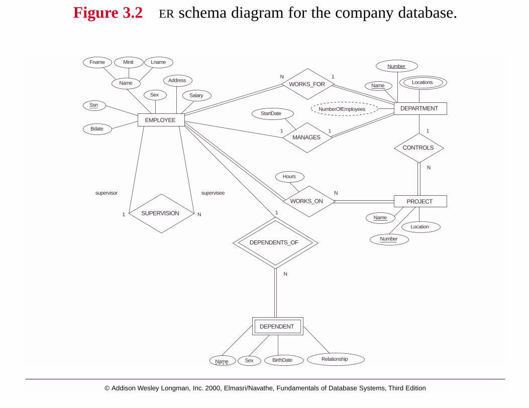
Company organized into DEPARTMENTs. Each department has unique name and a particular employee who manages the department. Start date for the manager is recorded. Department may have several locations.
A department controls a number of PROJECTs. Projects have a unique name, number and a single location.
Company’s EMPLOYEEs name, ssno, address, salary, sex and birth date are recorded. An employee is assigned to one department, but may work for several projects (not necessarily controlled by her dept). Number of hours/week an employee works on each project is recorded; The immediate supervisor for the employee.
Employee’s DEPENDENTs are tracked for health insurance purposes (dependent name, birthdate, relationship to employee).
Figure 3.2: ER Diagram
© Addison Wesley Longman, Inc. 2000, Elmasri/Navathe, Fundamentals of Database Systems, Third Edition
NumberFname
DEPENDENT
Minit Lname
Name Address
Sex Salary
Ssn___
EMPLOYEEBdate
WORKS_FOR
StartDate
MANAGES
NumberOfEmployees
NameLocations
DEPARTMENT
CONTROLS
PROJECT
Name
Location
Number______
WORKS_ON
DEPENDENTS_OF
N
1
Hours
N
Name Sex BirthDate Relationship
N
1
1 N
supervisor supervisee
SUPERVISION
1 1
N 1
Figure 3.2 ER schema diagram for the company database.
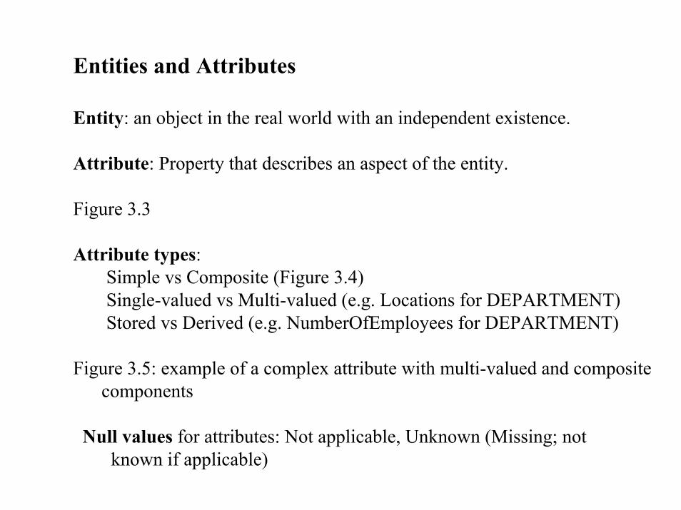
Entities and Attributes
Entity: an object in the real world with an independent existence.
Attribute: Property that describes an aspect of the entity.
Figure 3.3
Attribute types:Simple vs Composite (Figure 3.4)Single-valued vs Multi-valued (e.g. Locations for DEPARTMENT)Stored vs Derived (e.g. NumberOfEmployees for DEPARTMENT)
Figure 3.5: example of a complex attribute with multi-valued and compositecomponents
Null values for attributes: Not applicable, Unknown (Missing; notknown if applicable)
© Addison Wesley Longman, Inc. 2000, Elmasri/Navathe, Fundamentals of Database Systems, Third Edition
Headquarters = Houston
Name = Sunco Oil
President = John Smith
c 1
Name = John Smith
Address = 2311 Kirby, Houston, Texas 77001
Age = 55
HomePhone = 713-749-2630
e 1
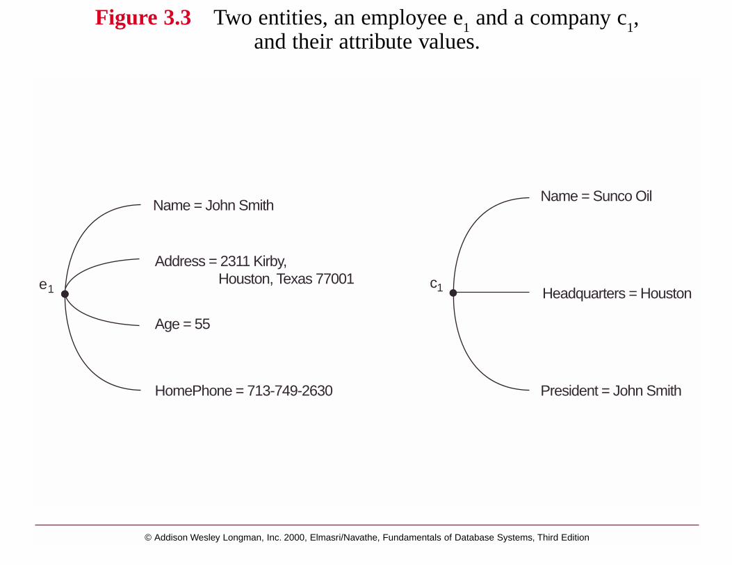
Figure 3.3 Two entities, an employee e1 and a company c1,and their attribute values.
© Addison Wesley Longman, Inc. 2000, Elmasri/Navathe, Fundamentals of Database Systems, Third Edition
Address
StreetAddress City State Zip
Number Street ApartmentNumber
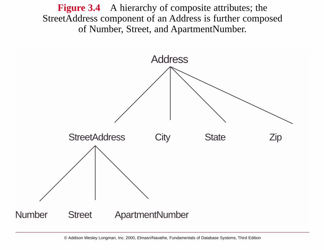
Figure 3.4 A hierarchy of composite attributes; theStreetAddress component of an Address is further composed
of Number, Street, and ApartmentNumber.
© Addison Wesley Longman, Inc. 2000, Elmasri/Navathe, Fundamentals of Database Systems, Third Edition
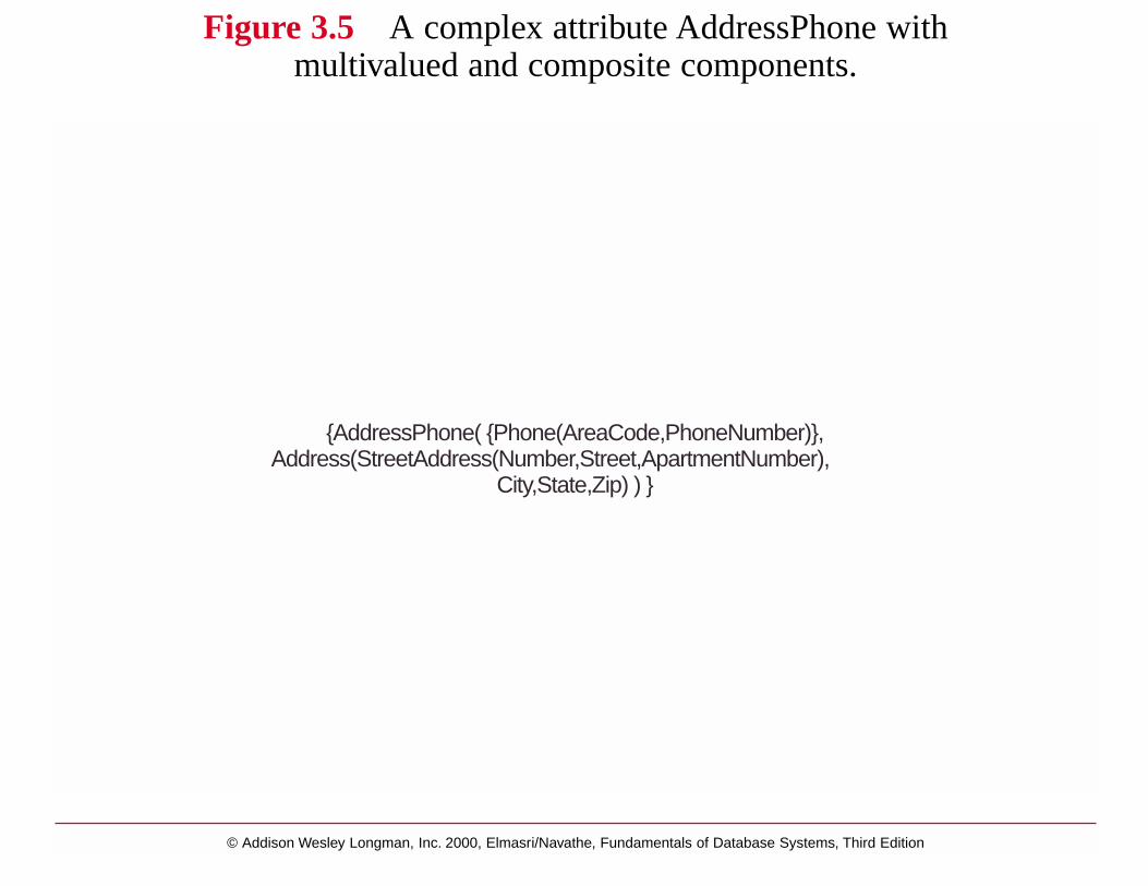
{AddressPhone( {Phone(AreaCode,PhoneNumber)},Address(StreetAddress(Number,Street,ApartmentNumber),
City,State,Zip) ) }
Figure 3.5 A complex attribute AddressPhone withmultivalued and composite components.

Entity Types, Value Sets, Key Attributes
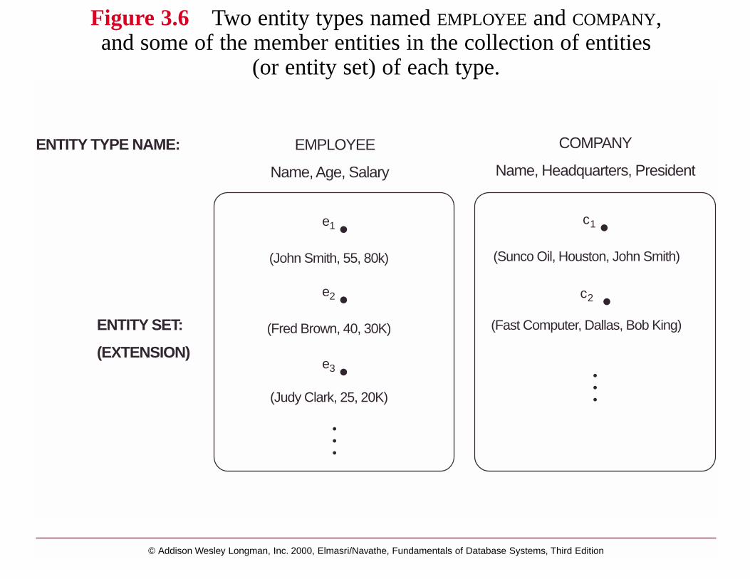
An entity type defines a set of entities that have the same attributes. See Figure 3.6
Rectangular box in ER Diagram denotes Entity TypesOvals denote Attributes
double-ovals: multi-valued attributetree structured ovals: composite attribute
Entity Set = Set of all entities of the same type.
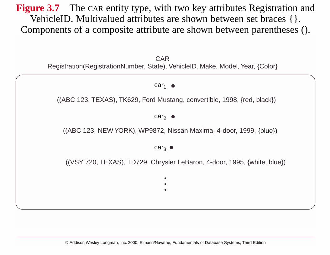
Key Attributes: uniquely identify each entity within an entity set(these are underlined in the ER Diagram)
Value Sets: or Domains for attributes.A: E -> P(V) A:attribute, E:Entity set, V: Value set
V = P(V1) x ... x P(Vn) for composite attributesA(e) denotes the value of attribute A for entity e
Figure 3.7 Car Entity Type
© Addison Wesley Longman, Inc. 2000, Elmasri/Navathe, Fundamentals of Database Systems, Third Edition
ENTITY TYPE NAME:
ENTITY SET:
(EXTENSION)
COMPANY
Name, Headquarters, President
EMPLOYEE
Name, Age, Salary
(John Smith, 55, 80k)
(Fred Brown, 40, 30K)
(Judy Clark, 25, 20K)
e 1
e 2
e 3
(Sunco Oil, Houston, John Smith)
(Fast Computer, Dallas, Bob King)
c 1
c 2
Figure 3.6 Two entity types named EMPLOYEE and COMPANY,and some of the member entities in the collection of entities
(or entity set) of each type.
© Addison Wesley Longman, Inc. 2000, Elmasri/Navathe, Fundamentals of Database Systems, Third Edition
CARRegistration(RegistrationNumber, State), VehicleID, Make, Model, Year, {Color}
((ABC 123, NEW YORK), WP9872, Nissan Maxima, 4-door, 1999,
((VSY 720, TEXAS), TD729, Chrysler LeBaron, 4-door, 1995, {white, blue})
((ABC 123, TEXAS), TK629, Ford Mustang, convertible, 1998, {red, black})
car1
car2
car3
{blue})
Figure 3.7 The CAR entity type, with two key attributes Registration andVehicleID. Multivalued attributes are shown between set braces {}.
Components of a composite attribute are shown between parentheses ().
Initial design of the COMPANY DATABASE
Figure 3.8
4 entity types:
DEPARTMENTEMPLOYEE PROJECTDEPENDENT
Not a perfect design! because it captures relationships between entities as attributes (in general not a good idea)
© Addison Wesley Longman, Inc. 2000, Elmasri/Navathe, Fundamentals of Database Systems, Third Edition
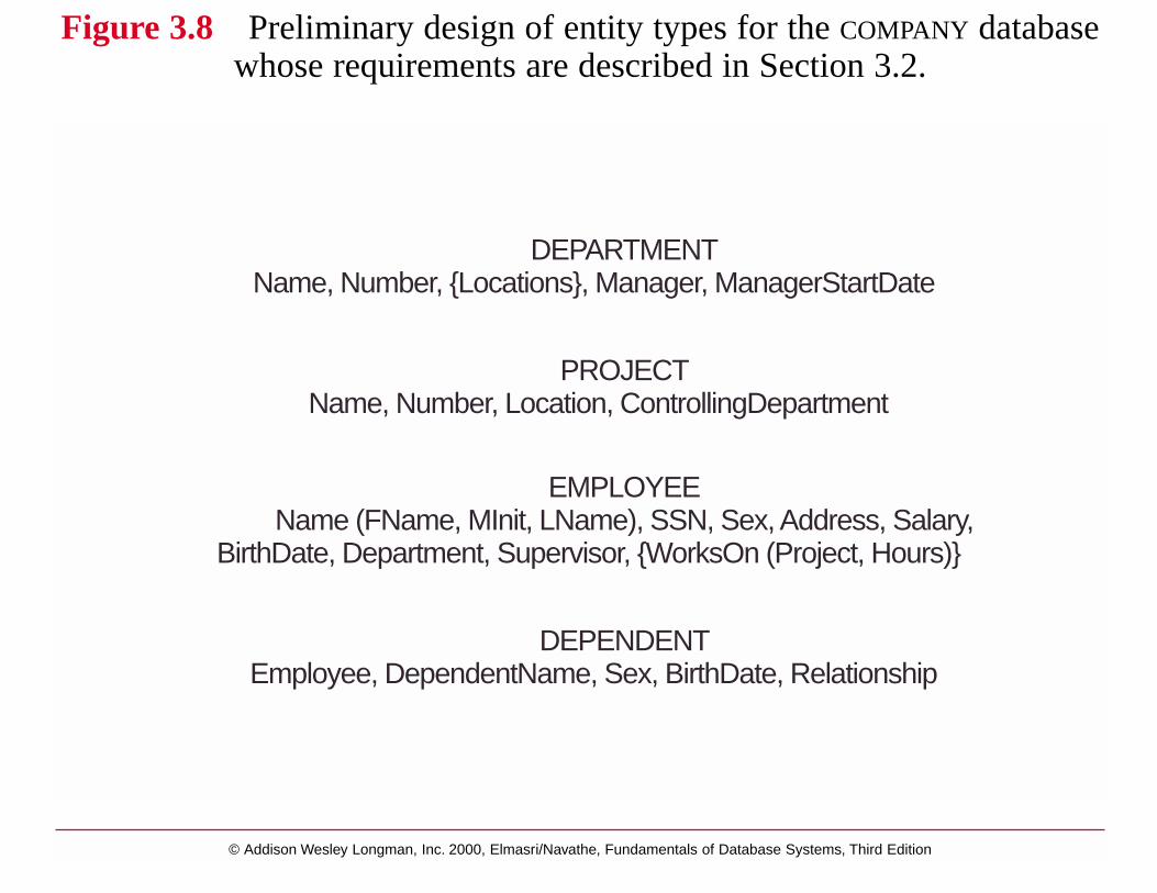
DEPARTMENTName, Number, {Locations}, Manager, ManagerStartDate
PROJECTName, Number, Location, ControllingDepartment
EMPLOYEEName (FName, MInit, LName), SSN, Sex, Address, Salary,
BirthDate, Department, Supervisor, {WorksOn (Project, Hours)}
DEPENDENTEmployee, DependentName, Sex, BirthDate, Relationship
Figure 3.8 Preliminary design of entity types for the COMPANY databasewhose requirements are described in Section 3.2.
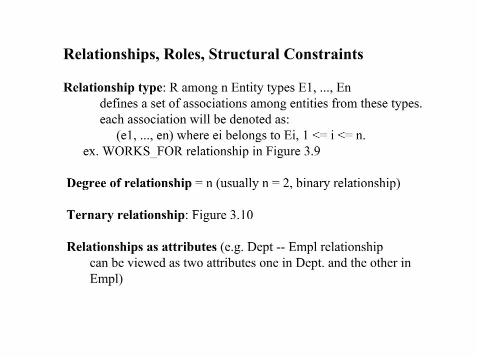
Relationships, Roles, Structural Constraints
Relationship type: R among n Entity types E1, ..., Endefines a set of associations among entities from these types.each association will be denoted as:
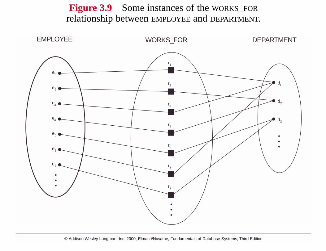
(e1, ..., en) where ei belongs to Ei, 1 <= i <= n.ex. WORKS_FOR relationship in Figure 3.9
Degree of relationship = n (usually n = 2, binary relationship)
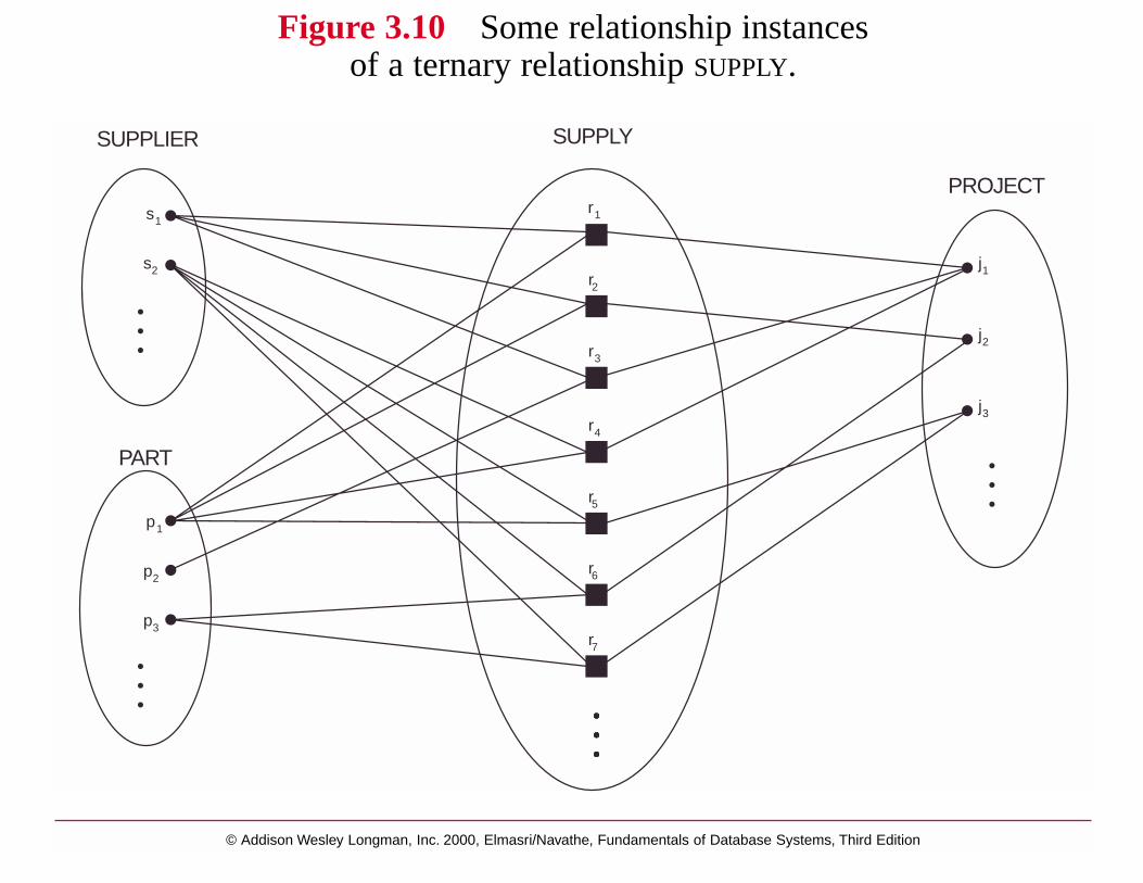
Ternary relationship: Figure 3.10
Relationships as attributes (e.g. Dept -- Empl relationshipcan be viewed as two attributes one in Dept. and the other inEmpl)
© Addison Wesley Longman, Inc. 2000, Elmasri/Navathe, Fundamentals of Database Systems, Third Edition
e 1
r 1
r 2
r 3
r 4
r 5
r 6
r 7
d 1
d 2
d 3
EMPLOYEE WORKS_FOR DEPARTMENT
e 2
e 3
e 4
e 5
e 6
e 7
Figure 3.9 Some instances of the WORKS_FOR
relationship between EMPLOYEE and DEPARTMENT.
© Addison Wesley Longman, Inc. 2000, Elmasri/Navathe, Fundamentals of Database Systems, Third Edition
SUPPLIER SUPPLY
PROJECTs 1
s 2
r 3
r 4
r 5
r 6
r 7
j 3
j 2
j 1
p 2
p 1
p 3
PART
r 2
r 1
Figure 3.10 Some relationship instancesof a ternary relationship SUPPLY.

Role names
Each entity participating in a relationship has a ROLE.e.g. Employee plays the role of worker and Department
plays the role of employer in the WORKS_FOR relationship type
Role names are more important in recursive relationshipsex. Figure 3.11

© Addison Wesley Longman, Inc. 2000, Elmasri/Navathe, Fundamentals of Database Systems, Third Edition
12
1
2
1
12
2
2
2
1
EMPLOYEESUPERVISION
e 1
e 2
e 3
e 4
e 5
e 6
e 7
r 1
r 2
r 3
r 4
r 5
r 6
Figure 3.11 The recursive relationship SUPERVISION, where the EMPLOYEE
entity type plays the two roles of supervisor (1) and supervisee (2).

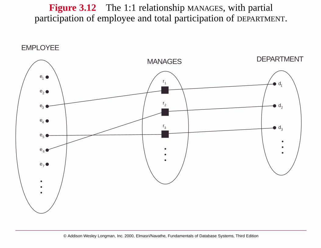
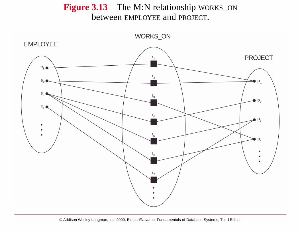
Structural Constraints on Relationships
2 types:
Cardinality Ratio Constraint (1-1, 1-N, M-N)
Participation Constraint
* total participation (existence dependency)
* partial participation
Figures 3.12 and 3.13
In ER Diagrams:total participation is denoted by double line and partial participation by single linecardinality ratios are mentioned as labels of edges
© Addison Wesley Longman, Inc. 2000, Elmasri/Navathe, Fundamentals of Database Systems, Third Edition
EMPLOYEE
MANAGES DEPARTMENT
e 1
e 2
e 3
e 4
e 5
e 6
e 7
r 1
r 2
r 3
d 1
d 2
d 3
Figure 3.12 The 1:1 relationship MANAGES, with partialparticipation of employee and total participation of DEPARTMENT.
© Addison Wesley Longman, Inc. 2000, Elmasri/Navathe, Fundamentals of Database Systems, Third Edition
WORKS_ONEMPLOYEE
PROJECTe 1
e 2
e 3
e 4
r 1
r 2
r 3
r 4
r 5
r 6
r 7
p 2
p 1
p 3
p 4
Figure 3.13 The M:N relationship WORKS_ON
between EMPLOYEE and PROJECT.

Attributes of relationships:
e.x. Hours attribute for WORKS_ON relationship
If relationship is 1-N or 1-1, these attributes can be be migrated to the entity sets involved in the relationship.
1-N: migrate to N side
1-1: migrate to either side
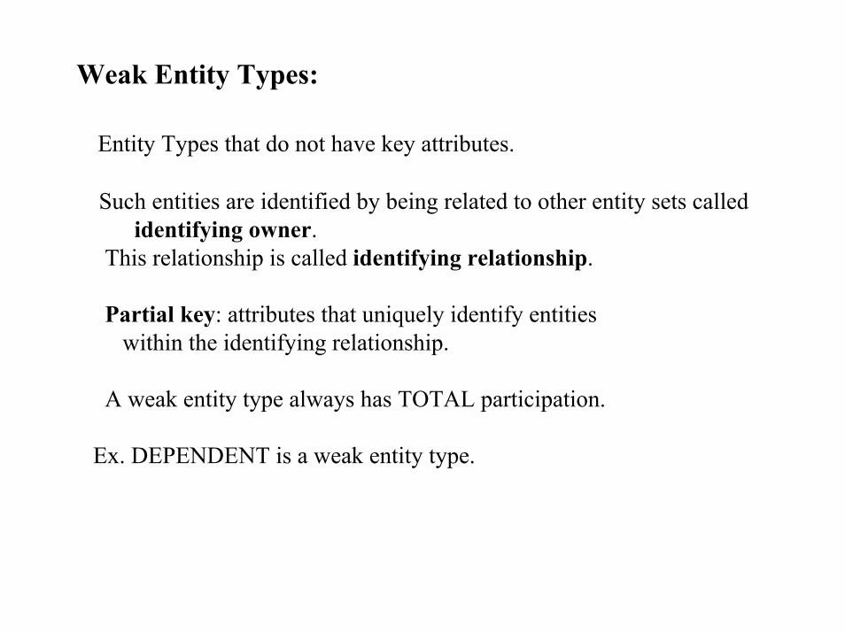
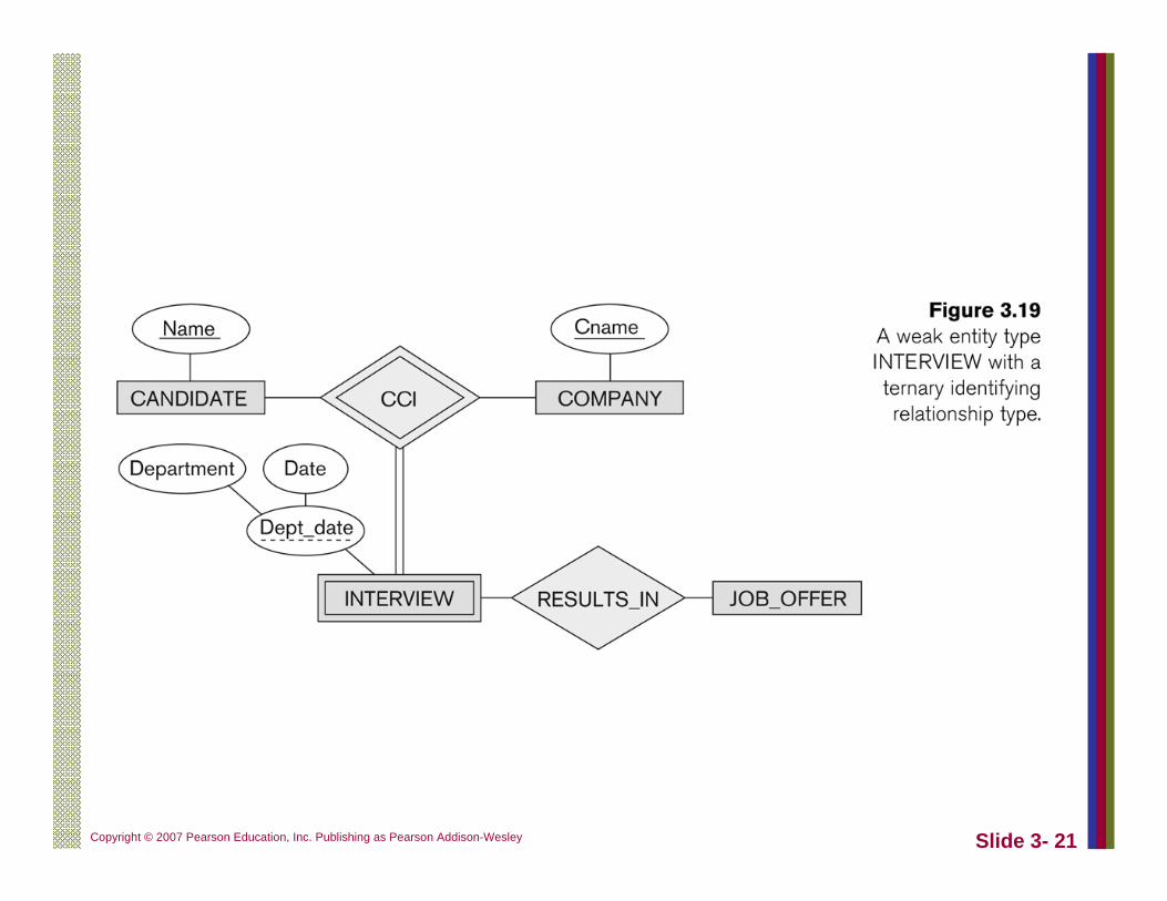
Weak Entity Types:
Entity Types that do not have key attributes.
Such entities are identified by being related to other entity sets called identifying owner.
This relationship is called identifying relationship.
Partial key: attributes that uniquely identify entitieswithin the identifying relationship.
A weak entity type always has TOTAL participation.
Ex. DEPENDENT is a weak entity type.
Notation for ER Diagrams:
Fig 3.14, 3.15
(Min,Max) notation encapsulates both types of structural constraints.This is more general than previous notation.
Min >=1 implies TOTAL participation
Min = 0 implies PARTIAL participation

©A
ddison Wesley Longm
an, Inc.2000, Elm
asri/Navathe, F
undamentals of D
atabase System
s, Third E
dition
E
ENTITY TYPE
WEAK ENTITY TYPE
RELATIONSHIP TYPE
IDENTIFYING RELATIONSHIP TYPE
ATTRIBUTE
MULTIVALUED ATTRIBUTE
Symbol Meaning
...
KEY ATTRIBUTE
COMPOSITE ATTRIBUTE
DERIVED ATTRIBUTE
E1
E1
E2
E2
E
R
R
R
1 N
(MIN, MAX)
TOTAL PARTICIPATION OF E2 IN R
CARDINALITY RATIO 1: N FOR E1:E2 IN R
STRUCTURAL CONSTRAINT (min, max)ON PARTICIPATION OF E IN R
Figure 3.14
Summ
ary of ER
diagram notation.
© Addison Wesley Longman, Inc. 2000, Elmasri/Navathe, Fundamentals of Database Systems, Third Edition
supervisor
(0,N)
(1,1)
controlled-project
(1,1)
Fname
manager
(0,1)StartDate
employee
SUPERVISION
Bdate
SalarySexName
AddressLnameMinit
EMPLOYEE
employee
(0,N)
(0,1)
superviseeCONTROLS
(0,N)controlling-department
department-managed
(1,1)
MANAGES
DEPARTMENT
Locations(4,N)
NumberOfEmployees
department
WORKS_FOR
DEPENDENTS_OFLocation
project
(1,N)WORKS_ON
Hours
worker
(1,N)
PROJECT
dependent(1,1)
RelationshipBirthDateSex
DEPENDENT
Ssn
Name
Number
Name
Name
Number
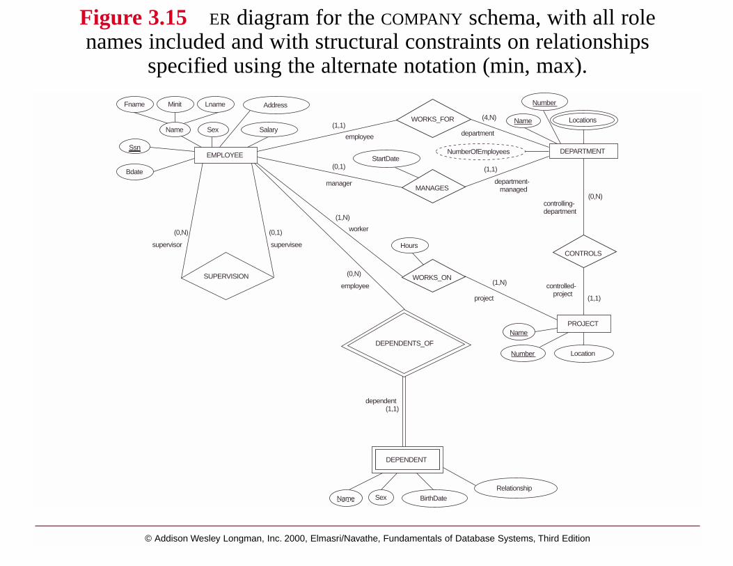
Figure 3.15 ER diagram for the COMPANY schema, with all rolenames included and with structural constraints on relationships
specified using the alternate notation (min, max).
Copyright © 2007 Ramez Elmasr and Shamkant B. Navathei
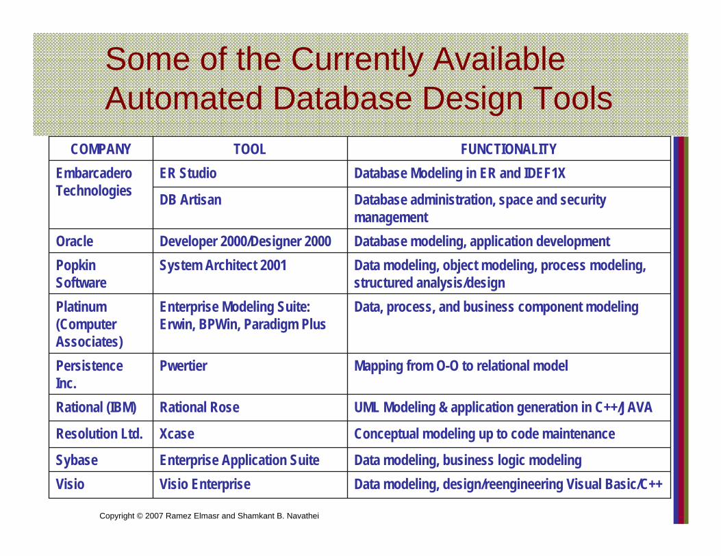
Some of the Currently Available Automated Database Design Tools
Data modeling, design/reengineering Visual Basic/C++Visio EnterpriseVisioData modeling, business logic modelingEnterprise Application SuiteSybase
Conceptual modeling up to code maintenanceXcaseResolution Ltd.
UML Modeling & application generation in C++/JAVARational RoseRational (IBM)
Mapping from O-O to relational modelPwertierPersistence Inc.
Data, process, and business component modelingEnterprise Modeling Suite: Erwin, BPWin, Paradigm Plus
Platinum (Computer Associates)
Data modeling, object modeling, process modeling, structured analysis/design
System Architect 2001PopkinSoftware
Database modeling, application developmentDeveloper 2000/Designer 2000Oracle
Database administration, space and security management
DB Artisan
Database Modeling in ER and IDEF1XER StudioEmbarcadero Technologies
FUNCTIONALITYTOOLCOMPANY

Copyright © 2007 Ramez Elmasr and Shamkant B. Navathei
UML class diagram for COMPANY database schema

Slide 3- 19Copyright © 2007 Pearson Education, Inc. Publishing as Pearson Addison-Wesley
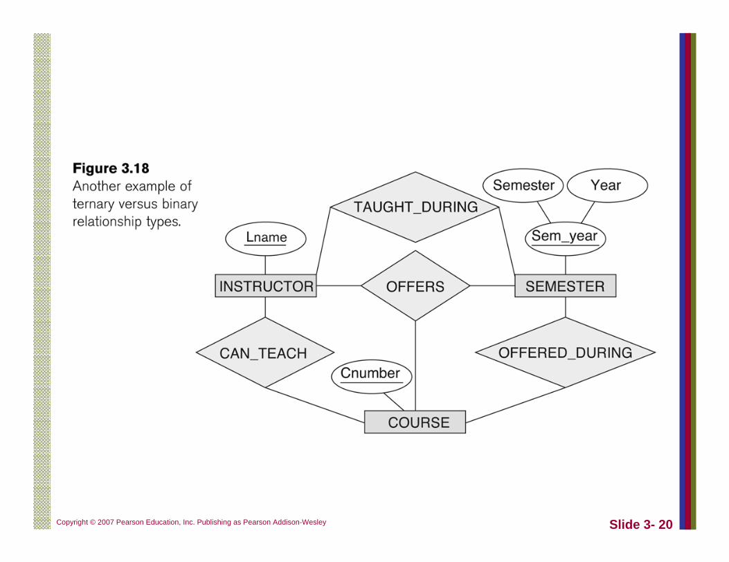
Slide 3- 20Copyright © 2007 Pearson Education, Inc. Publishing as Pearson Addison-Wesley
Slide 3- 21Copyright © 2007 Pearson Education, Inc. Publishing as Pearson Addison-Wesley