Embed Size (px)
Citation preview
Chapter 7Chapter 7
Arithmetic Operations and Arithmetic Operations and CircuitsCircuits
1
ObjectivesObjectives
You should be able to:You should be able to: Perform the four binary arithmetic Perform the four binary arithmetic
functions: addition, subtraction, functions: addition, subtraction, multiplication, and division.multiplication, and division.
Convert positive and negative numbers Convert positive and negative numbers to signed two’s-complement notation.to signed two’s-complement notation.
Perform two’s-complement, Perform two’s-complement, hexadecimal, and BCD arithmetic.hexadecimal, and BCD arithmetic.
2
ObjectivesObjectives(Continued)(Continued)
Explain the design and operation of a Explain the design and operation of a half-adder and a full-adder circuit.half-adder and a full-adder circuit.
Use full-adder ICs to implement Use full-adder ICs to implement arithmetic circuits.arithmetic circuits.
Explain the operation of a two’s-Explain the operation of a two’s-complement adder/subtractor circuit complement adder/subtractor circuit and a BCD adder circuit.and a BCD adder circuit.
Explain the function of an arithmetic Explain the function of an arithmetic logic unit (ALU).logic unit (ALU).
Implement arithmetic functions in Implement arithmetic functions in FPGAs using VHDL.FPGAs using VHDL.
3
Binary ArithmeticBinary Arithmetic
AdditionAddition When the sum exceeds 1, carry a 1 over When the sum exceeds 1, carry a 1 over
to the next-more-significant column.to the next-more-significant column. 0 + 0 = 0 carry 00 + 0 = 0 carry 0 0 + 1 = 1 carry 00 + 1 = 1 carry 0 1 + 0 = 1 carry 01 + 0 = 1 carry 0 1 + 1 = 0 carry 11 + 1 = 0 carry 1
5
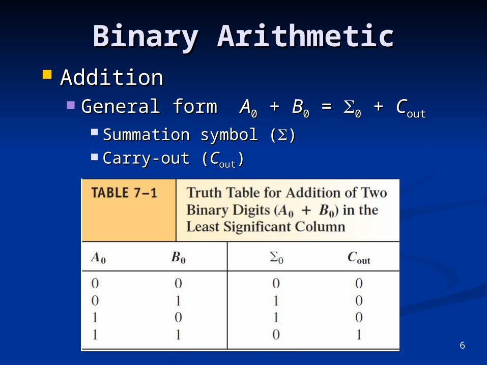
Binary ArithmeticBinary Arithmetic AdditionAddition
General form General form AA00 + + BB00 = = 00 + + CCoutout
Summation symbol (Summation symbol ()) Carry-out (Carry-out (CCoutout))
6
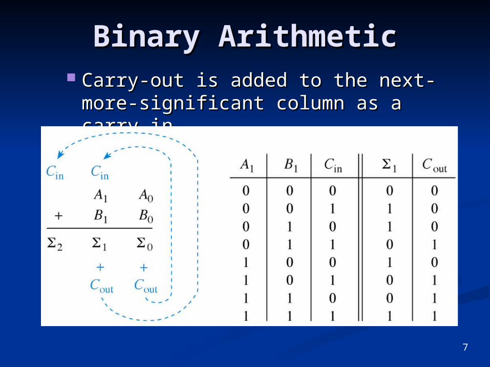
Binary ArithmeticBinary Arithmetic Carry-out is added to the next-more-Carry-out is added to the next-more-
significant column as a carry-in.significant column as a carry-in.
7
Binary ArithmeticBinary Arithmetic
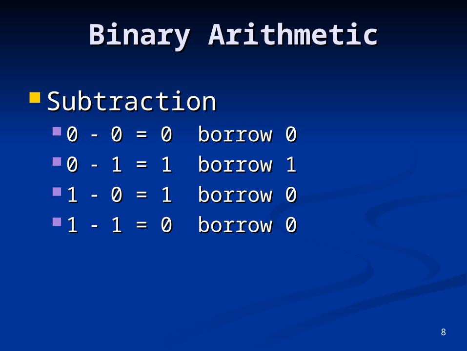
SubtractionSubtraction 0 0 0 = 0 borrow 0 0 = 0 borrow 0 0 0 1 = 1 borrow 1 1 = 1 borrow 1 1 1 0 = 1 borrow 0 0 = 1 borrow 0 1 1 1 = 0 borrow 0 1 = 0 borrow 0
8
Binary ArithmeticBinary Arithmetic SubtractionSubtraction
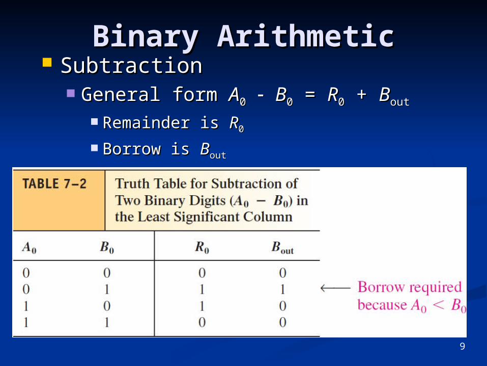
General form General form AA00 BB00 = = RR00 + + BBoutout
Remainder is Remainder is RR00
Borrow is Borrow is BBoutout
9
Binary ArithmeticBinary Arithmetic
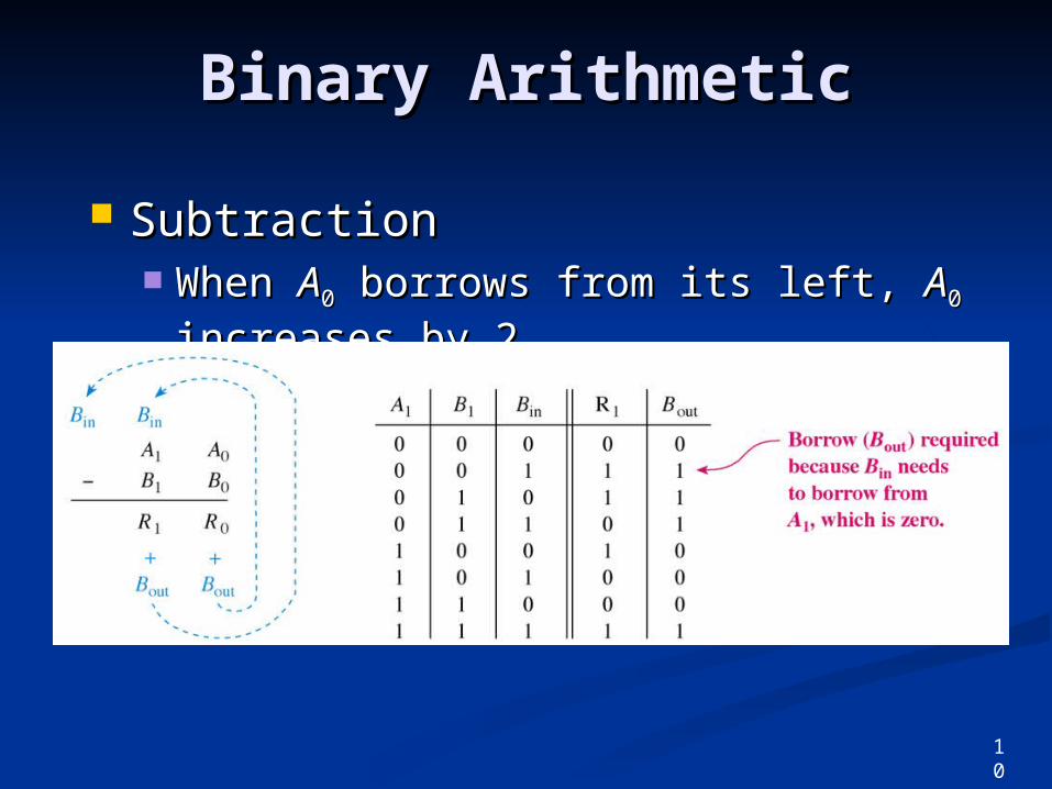
SubtractionSubtraction When When AA00 borrows from its left, borrows from its left, AA00
increases by 2increases by 21010..
10
Binary ArithmeticBinary Arithmetic
MultiplicationMultiplication Multiply the 2Multiply the 200 bit of the multiplier bit of the multiplier
times the multiplicand.times the multiplicand. Multiply the 2Multiply the 211 bit of the multiplier bit of the multiplier
times the multiplicand. Shift the times the multiplicand. Shift the result one position to the left.result one position to the left.
Repeat step 2 for the 2Repeat step 2 for the 222 bit of the bit of the multiplier, and for all remaining bits.multiplier, and for all remaining bits.
Take the sum of the partial products Take the sum of the partial products to get the final product.to get the final product.
11
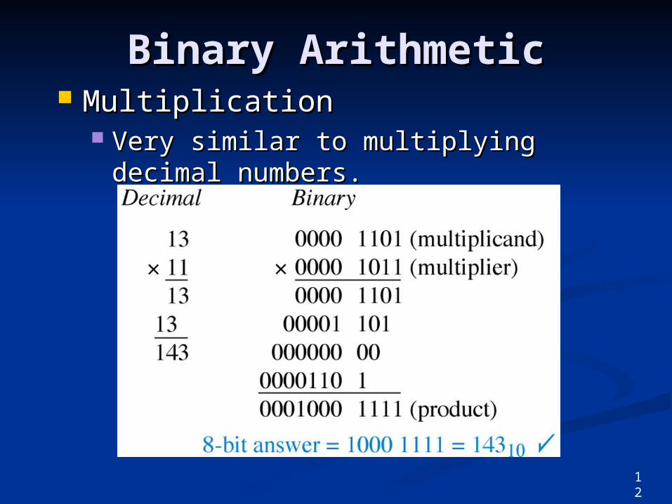
Binary ArithmeticBinary Arithmetic MultiplicationMultiplication
Very similar to multiplying decimal Very similar to multiplying decimal numbers.numbers.
12
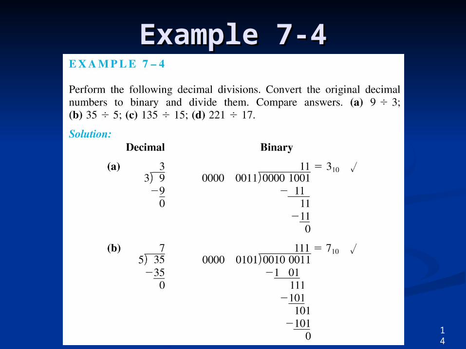
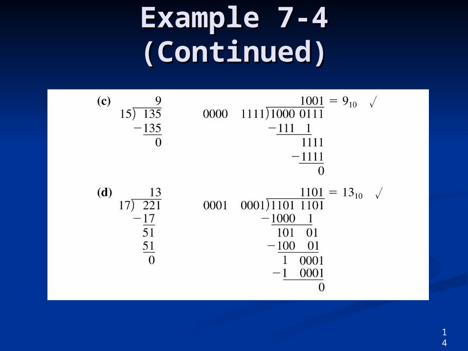
Binary ArithmeticBinary ArithmeticDivisionDivision
The same as decimal The same as decimal division. division.
This process is illustrated in This process is illustrated in Example 7-4.Example 7-4.
13
14
Example 7-4Example 7-4
14
Example 7-4 Example 7-4 (Continued)(Continued)
Two’s-Complement Two’s-Complement RepresentationRepresentation
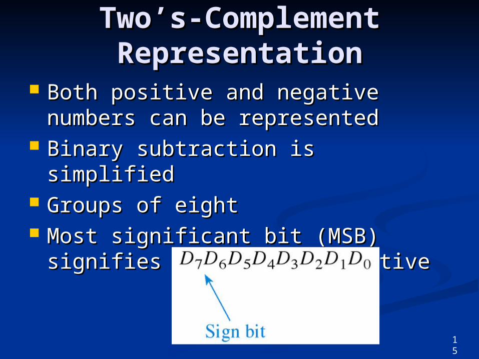
Both positive and negative numbers Both positive and negative numbers can be representedcan be represented
Binary subtraction is simplifiedBinary subtraction is simplified Groups of eightGroups of eight Most significant bit (MSB) signifies Most significant bit (MSB) signifies
positive or negativepositive or negative
15
Two’s-Complement Two’s-Complement RepresentationRepresentation
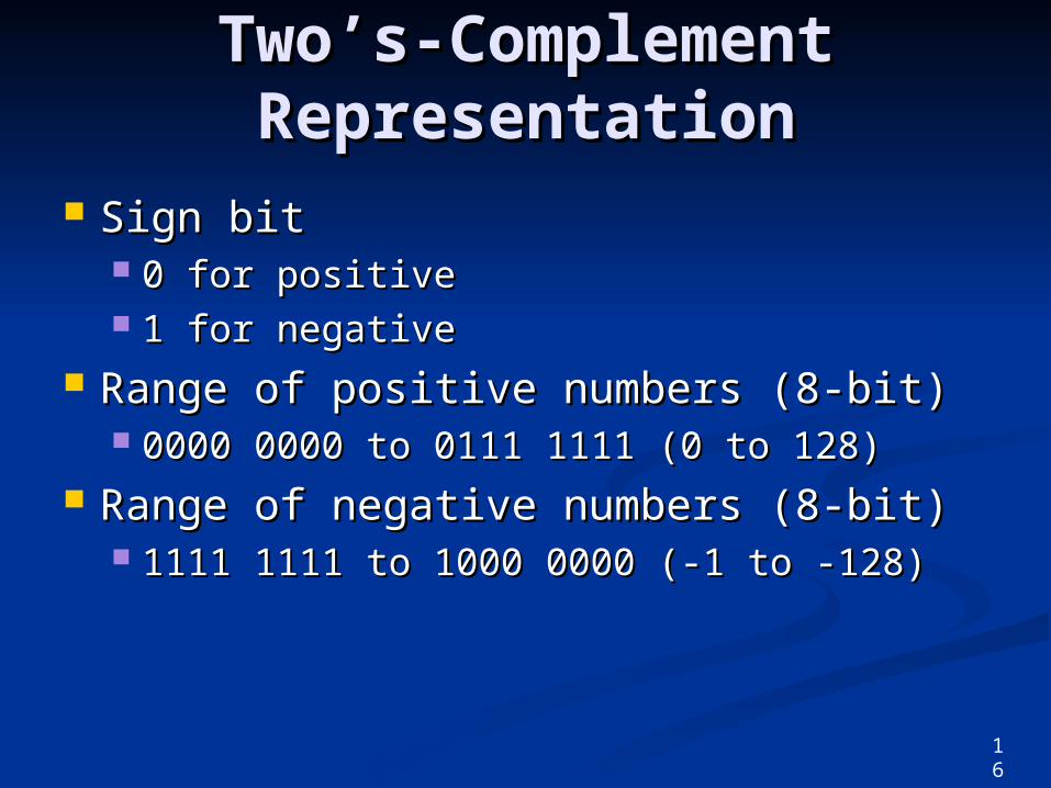
Sign bitSign bit 0 for positive0 for positive 1 for negative1 for negative
Range of positive numbers (8-bit)Range of positive numbers (8-bit) 0000 0000 to 0111 1111 (0 to 128)0000 0000 to 0111 1111 (0 to 128)
Range of negative numbers (8-bit)Range of negative numbers (8-bit) 1111 1111 to 1000 0000 (-1 to -128)1111 1111 to 1000 0000 (-1 to -128)
16
Two’s-Complement Two’s-Complement RepresentationRepresentation
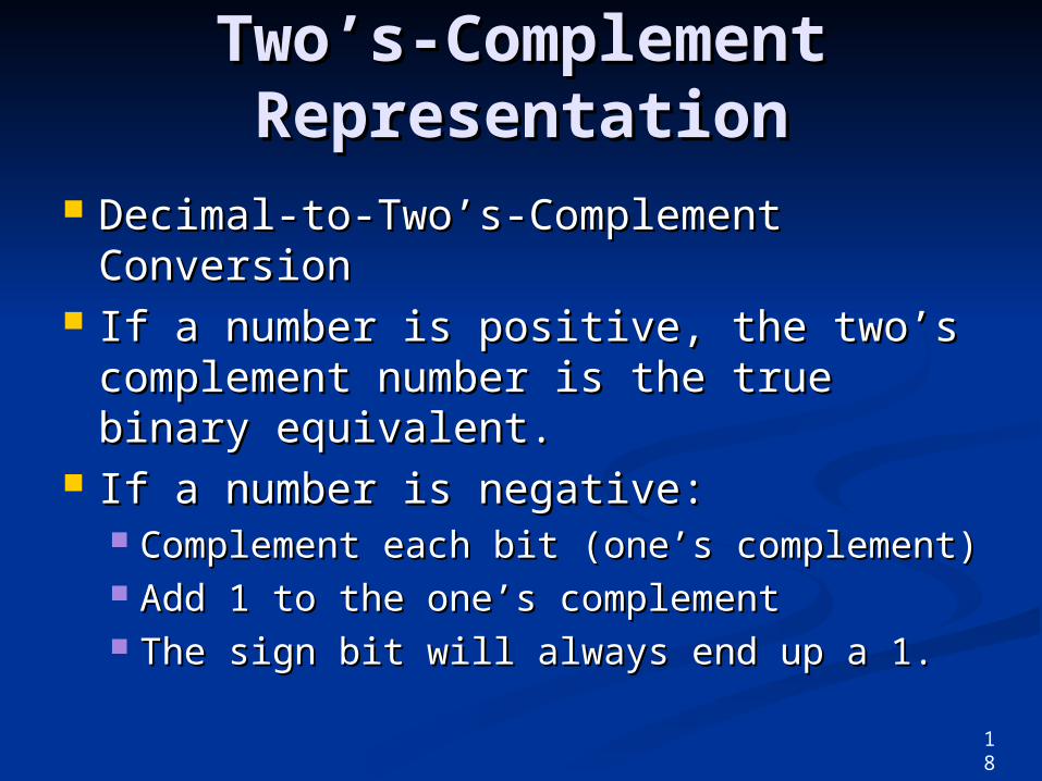
Decimal-to-Two’s-Complement Decimal-to-Two’s-Complement ConversionConversion
If a number is positive, the two’s If a number is positive, the two’s complement number is the true binary complement number is the true binary equivalent.equivalent.
If a number is negative:If a number is negative: Complement each bit (one’s complement)Complement each bit (one’s complement) Add 1 to the one’s complementAdd 1 to the one’s complement The sign bit will always end up a 1.The sign bit will always end up a 1.
18
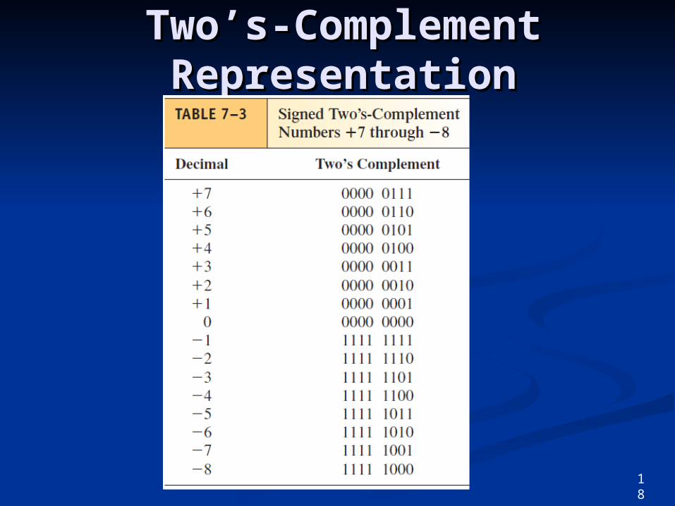
Two’s-Complement Two’s-Complement RepresentationRepresentation
18
Two’s-Complement Two’s-Complement RepresentationRepresentation
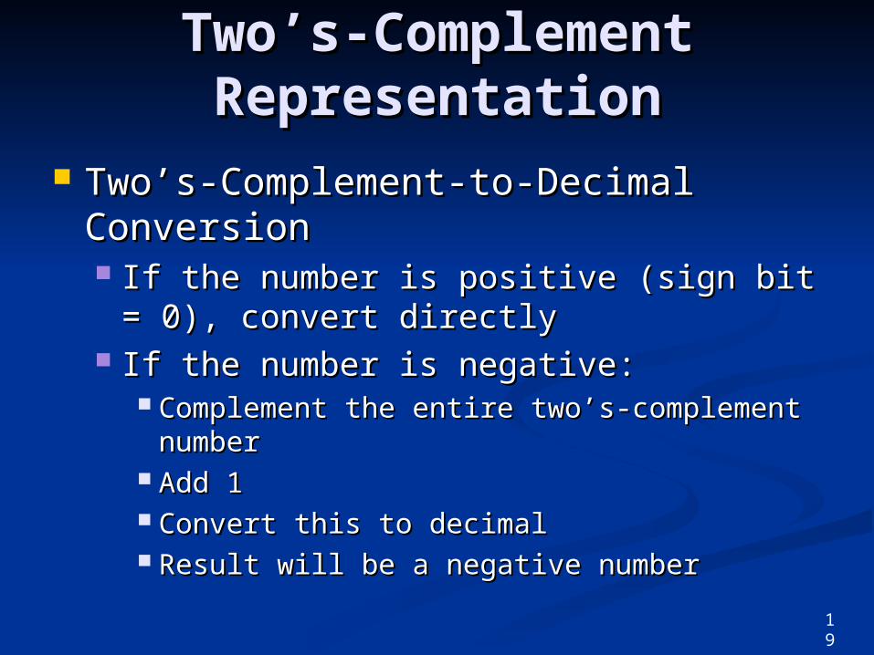
Two’s-Complement-to-Decimal Two’s-Complement-to-Decimal ConversionConversion If the number is positive (sign bit = 0), If the number is positive (sign bit = 0),
convert directlyconvert directly If the number is negative:If the number is negative:
Complement the entire two’s-complement Complement the entire two’s-complement numbernumber
Add 1Add 1 Convert this to decimalConvert this to decimal Result will be a negative numberResult will be a negative number
19
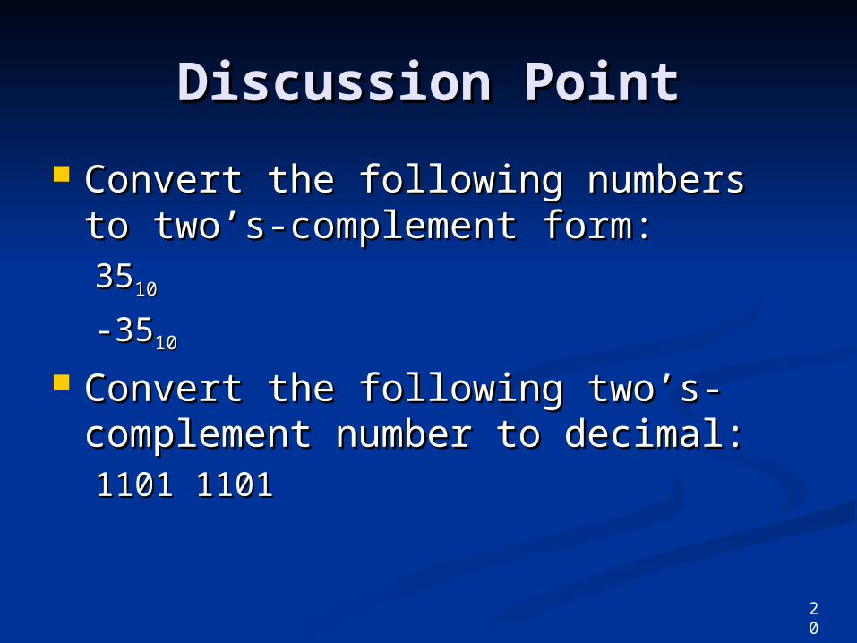
Discussion PointDiscussion Point
Convert the following numbers to Convert the following numbers to two’s-complement form:two’s-complement form:35351010
-35-351010
Convert the following two’s-Convert the following two’s-complement number to decimal:complement number to decimal:1101 11011101 1101
20
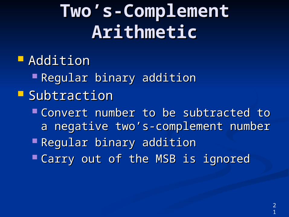
Two’s-Complement Two’s-Complement ArithmeticArithmetic
AdditionAddition Regular binary additionRegular binary addition
SubtractionSubtraction Convert number to be subtracted to a Convert number to be subtracted to a
negative two’s-complement numbernegative two’s-complement number Regular binary additionRegular binary addition Carry out of the MSB is ignoredCarry out of the MSB is ignored
21
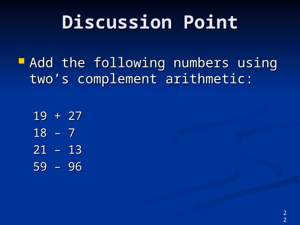
Discussion PointDiscussion Point
Add the following numbers using Add the following numbers using two’s complement arithmetic:two’s complement arithmetic:
19 + 2719 + 27
18 – 718 – 7
21 – 1321 – 13
59 – 9659 – 96
22
Hexadecimal ArithmeticHexadecimal Arithmetic
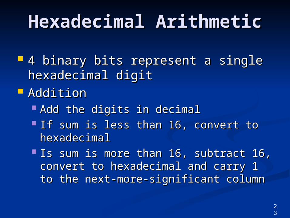
4 binary bits represent a single 4 binary bits represent a single hexadecimal digithexadecimal digit
AdditionAddition Add the digits in decimalAdd the digits in decimal If sum is less than 16, convert to If sum is less than 16, convert to
hexadecimalhexadecimal Is sum is more than 16, subtract 16, Is sum is more than 16, subtract 16,
convert to hexadecimal and carry 1 to convert to hexadecimal and carry 1 to the next-more-significant columnthe next-more-significant column
23
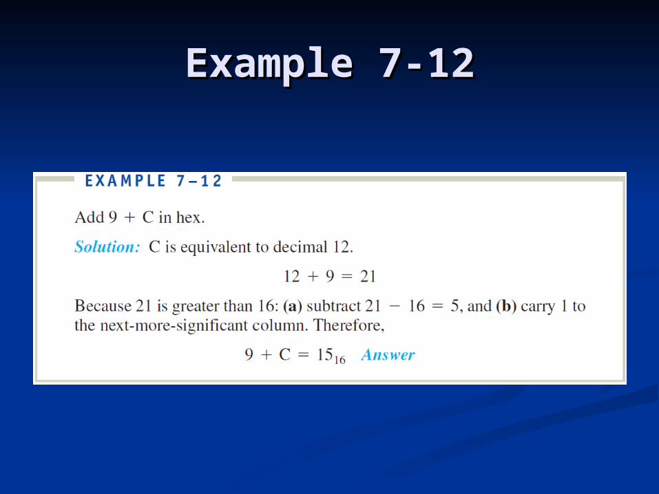
Example 7-12Example 7-12
Hexadecimal ArithmeticHexadecimal Arithmetic
SubtractionSubtraction When you borrow, the borrower When you borrow, the borrower
increases by 16increases by 16 See example 7-15See example 7-15
24
25
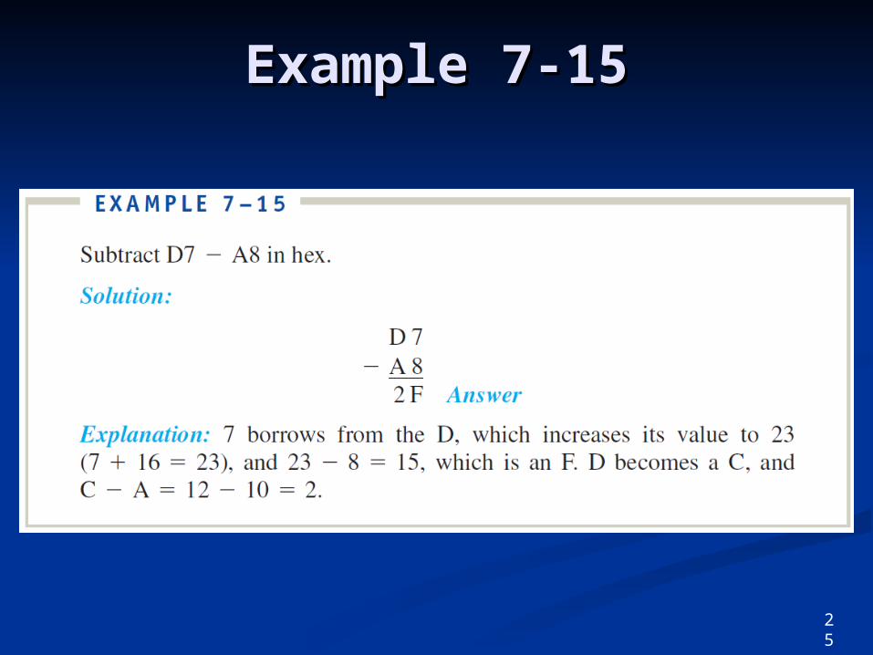
Example 7-15Example 7-15
BCD ArithmeticBCD Arithmetic
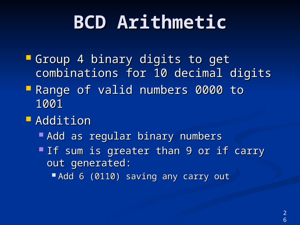
Group 4 binary digits to get Group 4 binary digits to get combinations for 10 decimal digitscombinations for 10 decimal digits
Range of valid numbers 0000 to Range of valid numbers 0000 to 10011001
AdditionAddition Add as regular binary numbersAdd as regular binary numbers If sum is greater than 9 or if carry If sum is greater than 9 or if carry
out generated:out generated: Add 6 (0110) saving any carry outAdd 6 (0110) saving any carry out
26
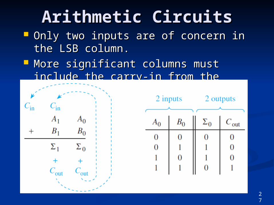
Arithmetic CircuitsArithmetic Circuits Only two inputs are of concern in the Only two inputs are of concern in the
LSB column.LSB column. More significant columns must include More significant columns must include
the carry-in from the previous column the carry-in from the previous column as a third input.as a third input.
27
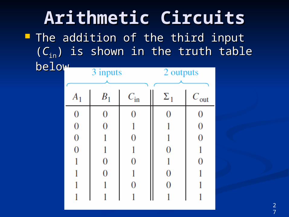
Arithmetic CircuitsArithmetic Circuits The addition of the third input (The addition of the third input (CCinin) is ) is
shown in the truth table below.shown in the truth table below.
27
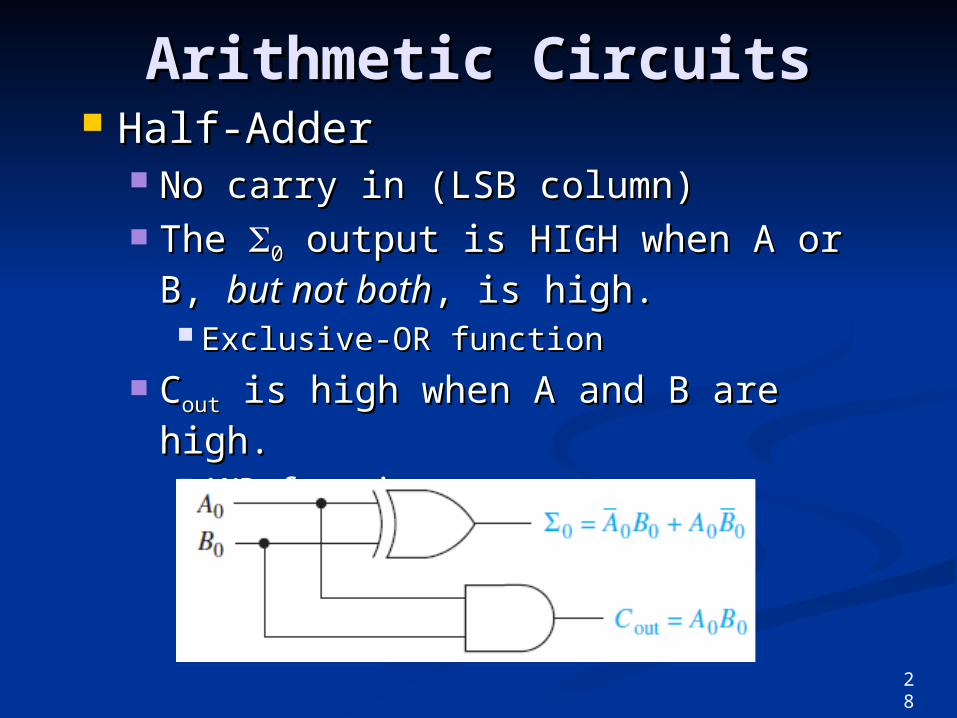
Arithmetic CircuitsArithmetic Circuits Half-AdderHalf-Adder
No carry in (LSB column)No carry in (LSB column) The The 00 output is HIGH when A or B, output is HIGH when A or B,
but not bothbut not both, is high., is high. Exclusive-OR functionExclusive-OR function
CCoutout is high when A and B are high. is high when A and B are high. AND functionAND function
28
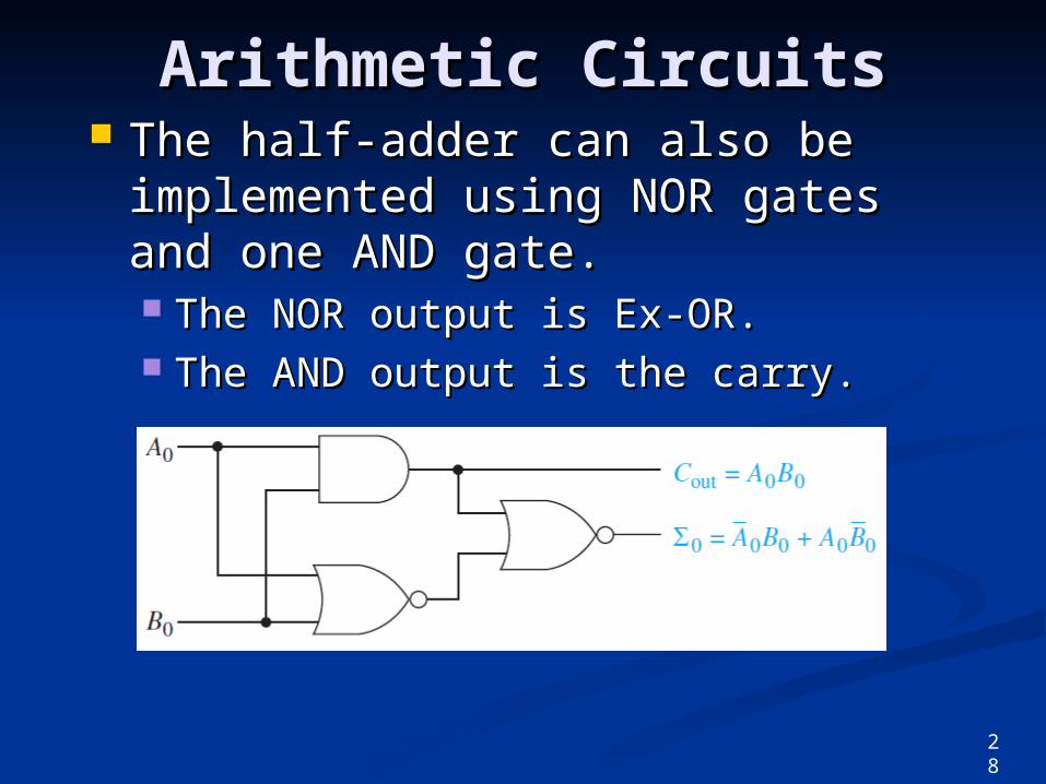
Arithmetic CircuitsArithmetic Circuits The half-adder can also be The half-adder can also be
implemented using NOR gates and implemented using NOR gates and one AND gate.one AND gate. The NOR output is Ex-OR.The NOR output is Ex-OR. The AND output is the carry.The AND output is the carry.
28
Arithmetic CircuitsArithmetic Circuits
Full-AdderFull-Adder Provides for a carry inputProvides for a carry input The The 11 output is high when the 3-bit output is high when the 3-bit
input is input is oddodd.. Even parity generatorEven parity generator
CCoutout is high when any is high when any twotwo inputs are inputs are high.high. 3 AND gates and an OR3 AND gates and an OR
29
Arithmetic CircuitsArithmetic Circuits
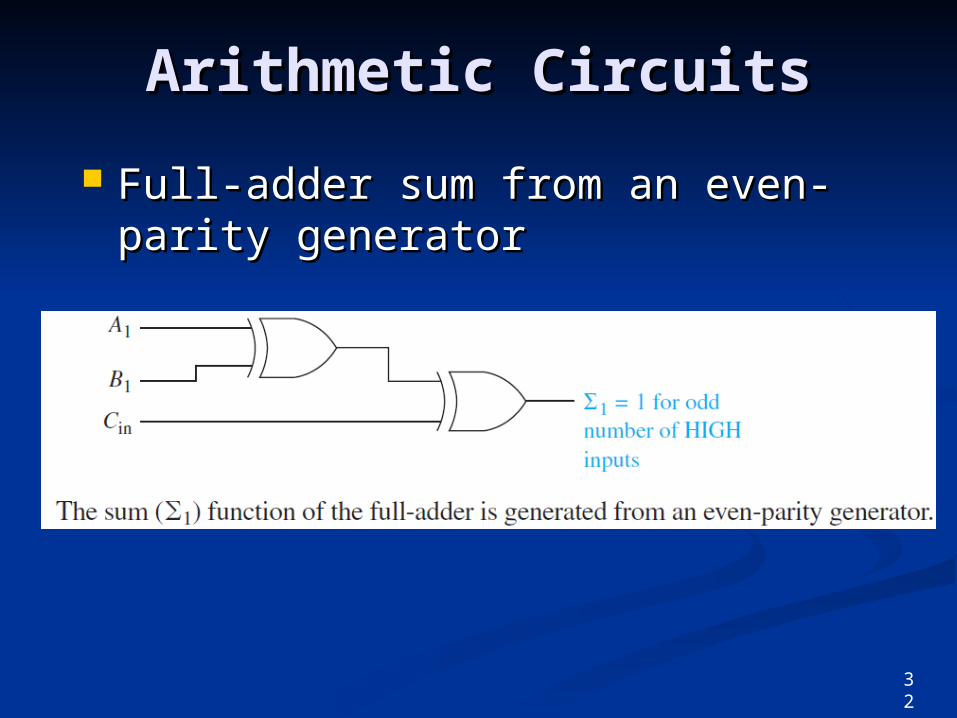
Full-adder sum from an even-Full-adder sum from an even-parity generatorparity generator
32
Arithmetic CircuitsArithmetic Circuits
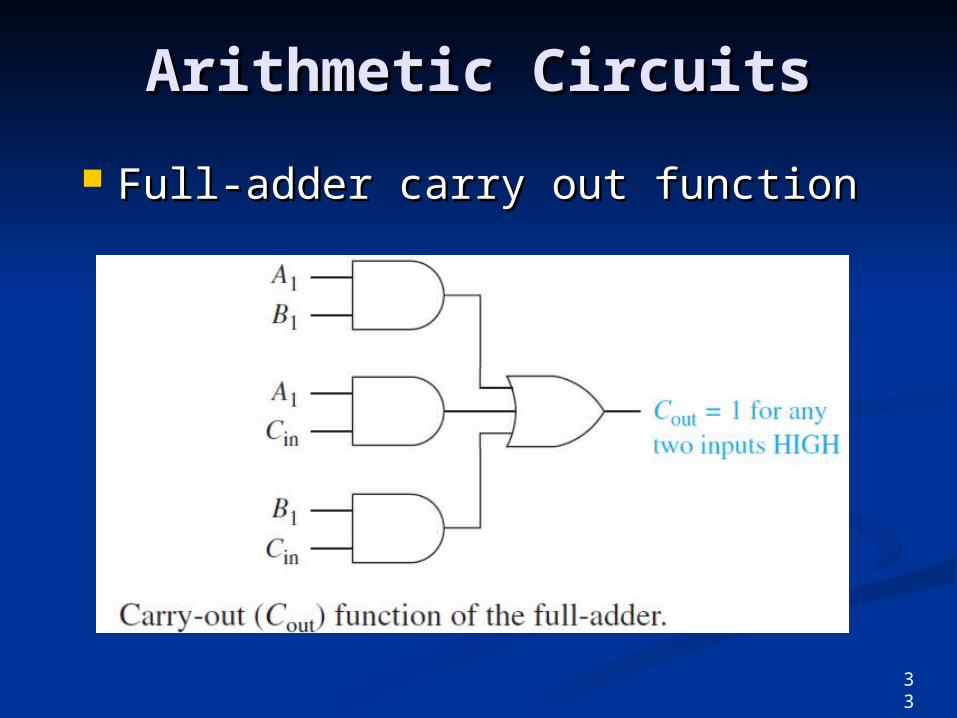
Full-adder carry out functionFull-adder carry out function
33
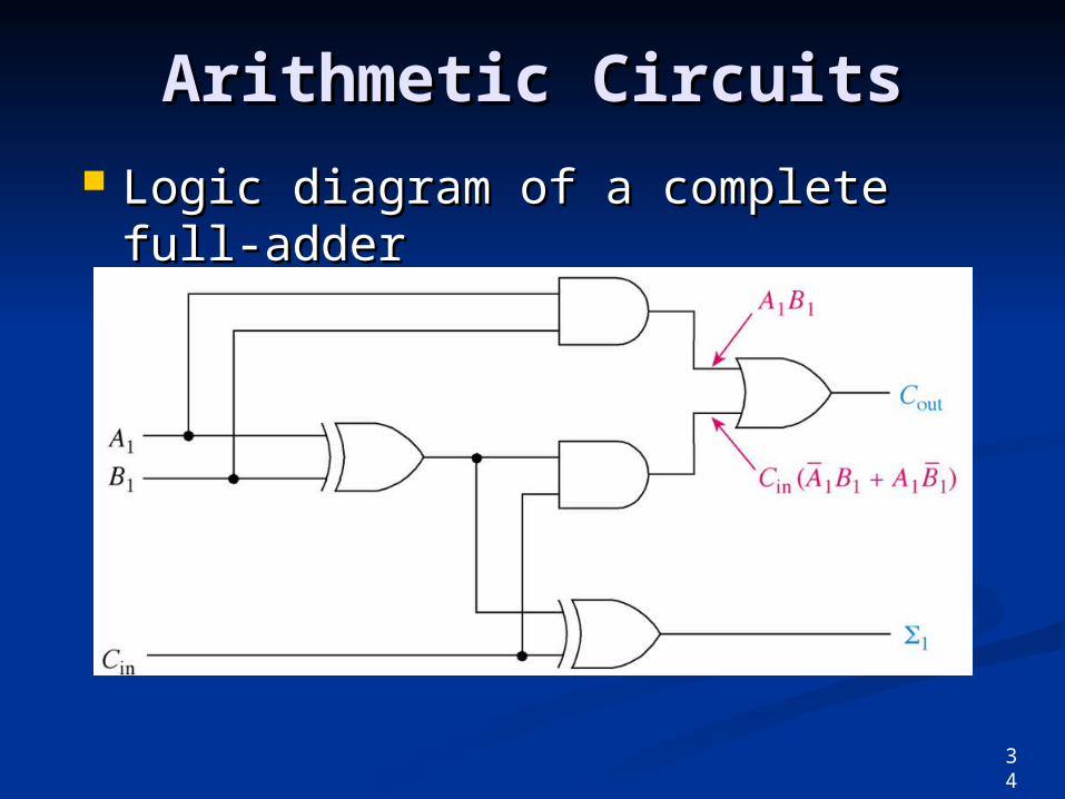
Arithmetic CircuitsArithmetic Circuits Logic diagram of a complete full-Logic diagram of a complete full-
adderadder
34
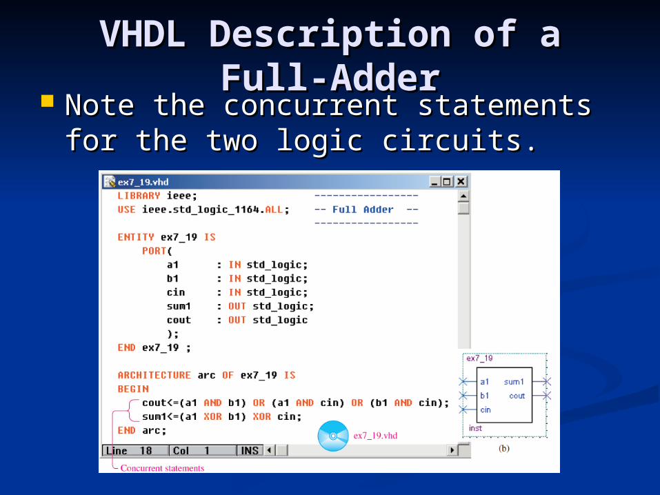
VHDL Description of a Full-VHDL Description of a Full-AdderAdder
Note the concurrent statements for Note the concurrent statements for the two logic circuits.the two logic circuits.
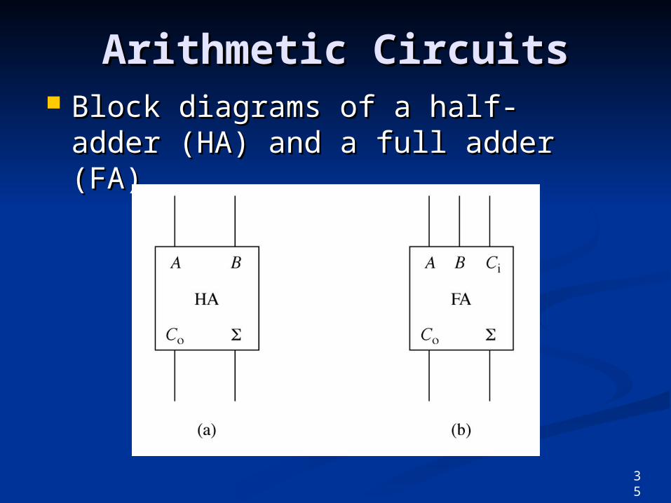
Arithmetic CircuitsArithmetic Circuits Block diagrams of a half-adder Block diagrams of a half-adder
(HA) and a full adder (FA).(HA) and a full adder (FA).
35
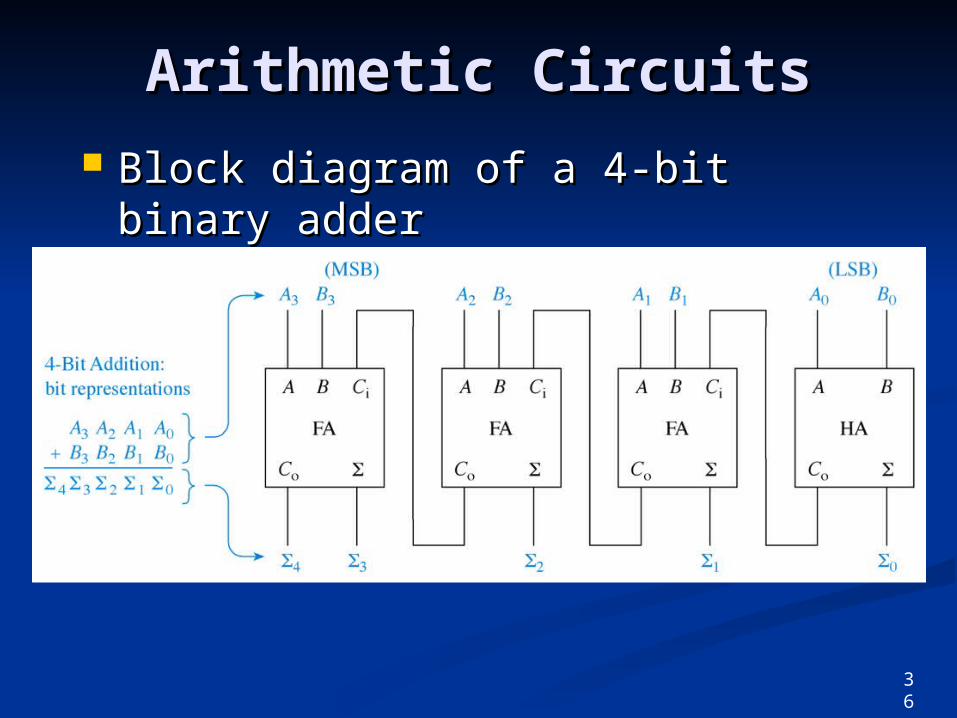
Arithmetic CircuitsArithmetic Circuits Block diagram of a 4-bit binary Block diagram of a 4-bit binary
adderadder
36
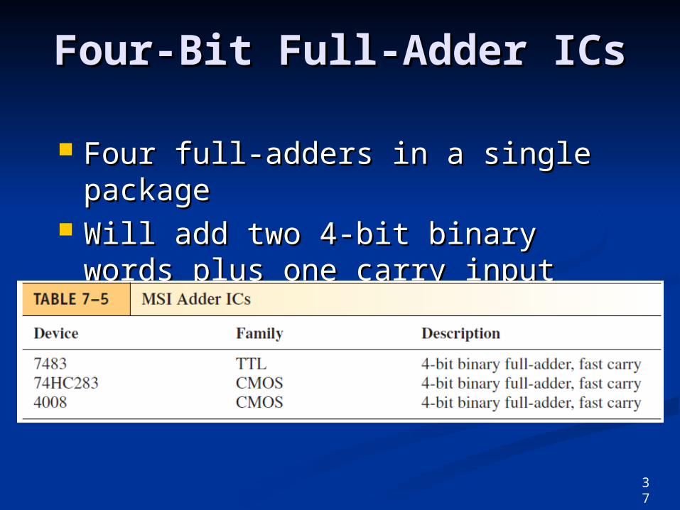
Four-Bit Full-Adder ICsFour-Bit Full-Adder ICs
Four full-adders in a single Four full-adders in a single packagepackage
Will add two 4-bit binary words Will add two 4-bit binary words plus one carry input bit.plus one carry input bit.
37
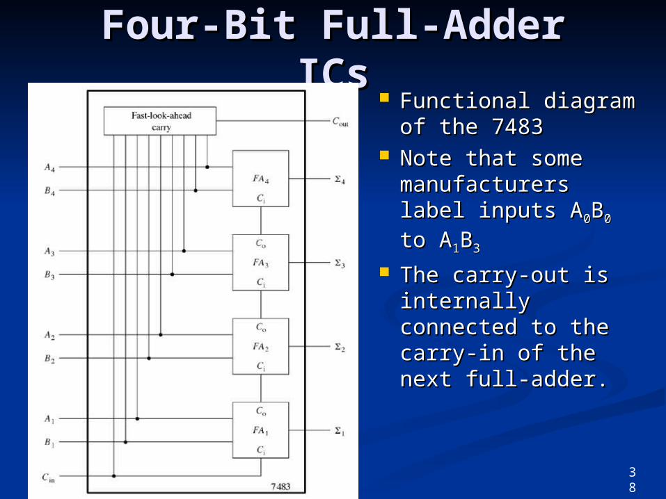
Four-Bit Full-Adder ICsFour-Bit Full-Adder ICs Functional diagram Functional diagram
of the 7483 of the 7483 Note that some Note that some
manufacturers manufacturers label inputs Alabel inputs A00BB00 to to AA11BB33
The carry-out is The carry-out is internally internally connected to the connected to the carry-in of the next carry-in of the next full-adder.full-adder.
38
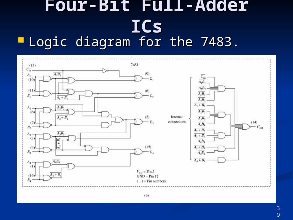
Four-Bit Full-Adder ICsFour-Bit Full-Adder ICs Logic diagram for the 7483.Logic diagram for the 7483.
39
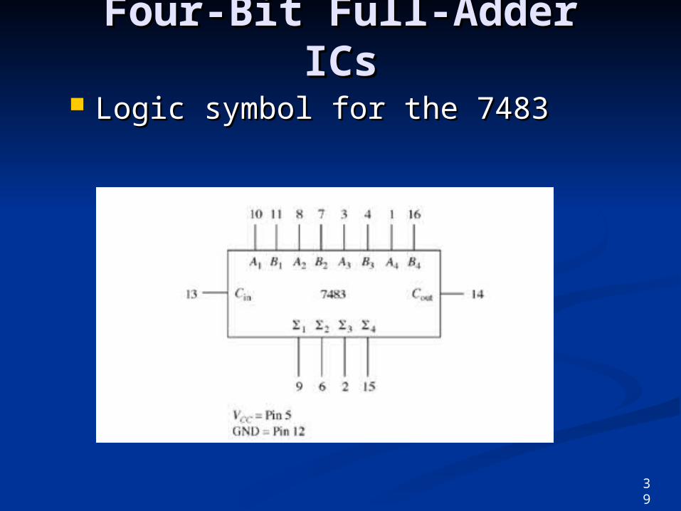
Four-Bit Full-Adder ICsFour-Bit Full-Adder ICs
Logic symbol for the 7483Logic symbol for the 7483
39
Four-Bit Full-Adder ICsFour-Bit Full-Adder ICs
Fast-look-ahead carryFast-look-ahead carry Evaluates 4 low-order inputsEvaluates 4 low-order inputs High-order bits added at same timeHigh-order bits added at same time Eliminates waiting for propagation Eliminates waiting for propagation
rippleripple
40
VHDL Adders Using VHDL Adders Using Integer ArithmeticInteger Arithmetic
Uses arithmetic operator and Uses arithmetic operator and integer data typeinteger data type Integer data type allows for values Integer data type allows for values
other than other than 1 and 0.1 and 0.
Integer range must be specified.Integer range must be specified. Software uses the range to determine Software uses the range to determine
the number of inputs required.the number of inputs required.
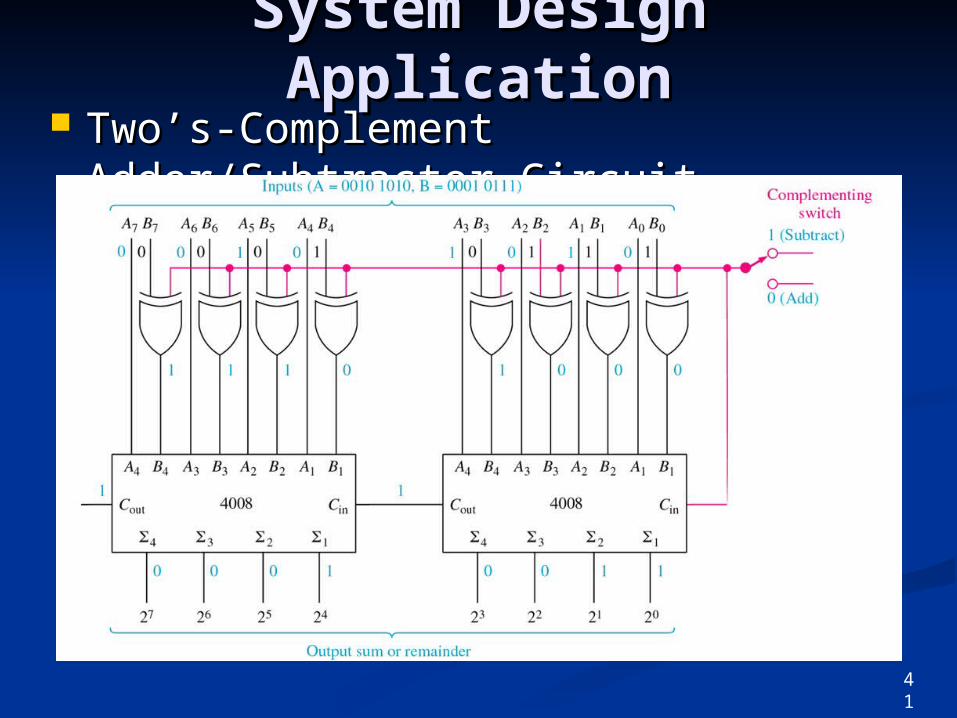
System Design System Design ApplicationApplication
Two’s-Complement Two’s-Complement Adder/Subtractor CircuitAdder/Subtractor Circuit
41
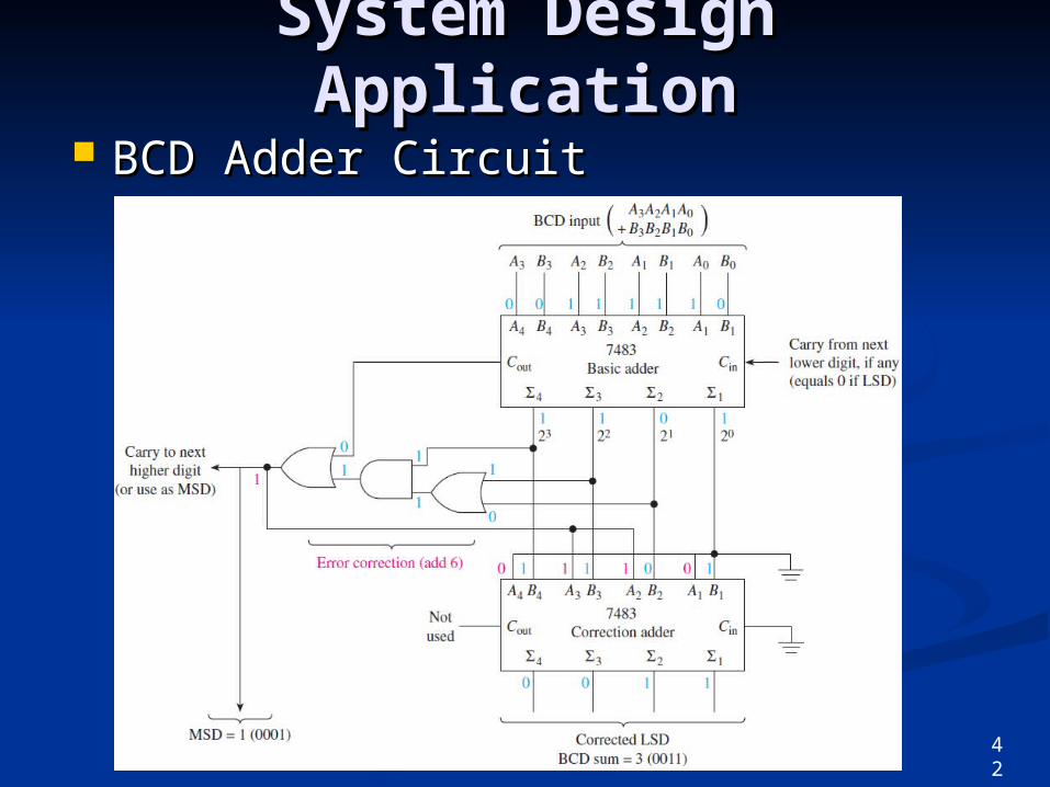
System Design System Design ApplicationApplication
BCD Adder CircuitBCD Adder Circuit
42
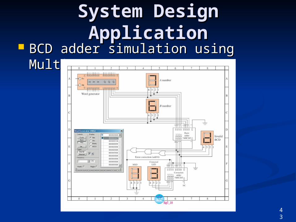
System Design System Design ApplicationApplication
BCD adder simulation using BCD adder simulation using MultiSIM:MultiSIM:
43
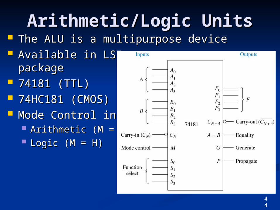
Arithmetic/Logic UnitsArithmetic/Logic Units The ALU is a multipurpose deviceThe ALU is a multipurpose device Available in LSI Available in LSI
packagepackage 74181 (TTL)74181 (TTL) 74HC181 (CMOS)74HC181 (CMOS) Mode Control inputMode Control input
Arithmetic (M = L)Arithmetic (M = L) Logic (M = H)Logic (M = H)
44
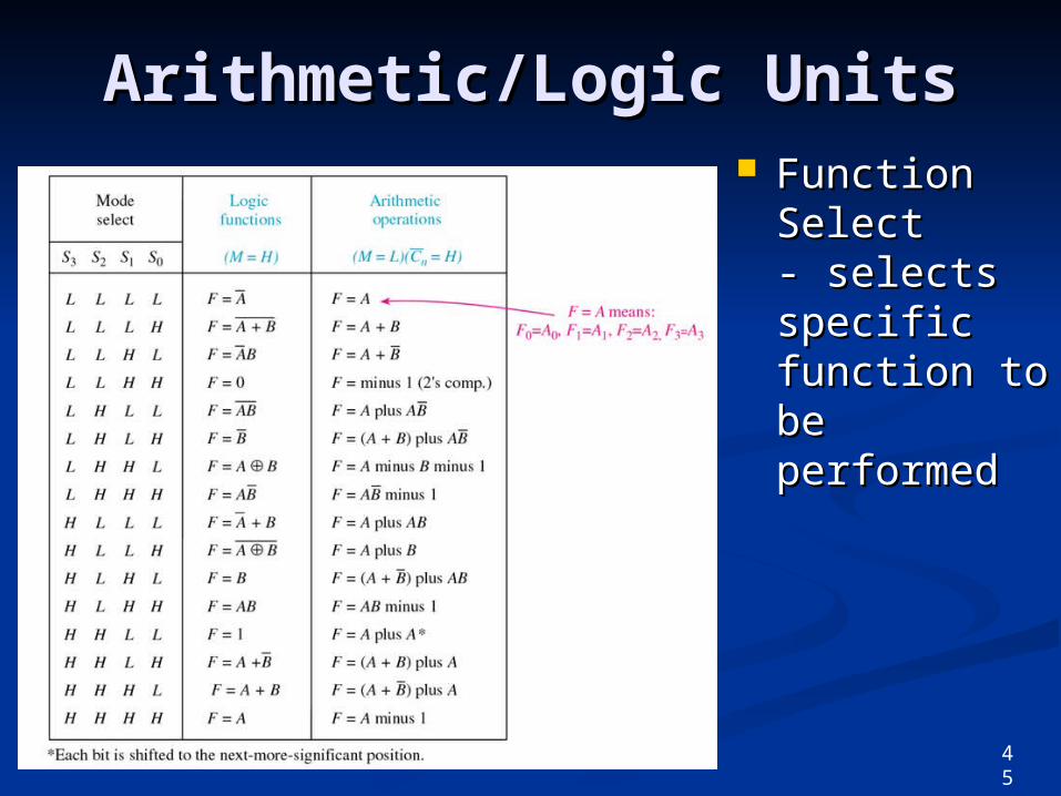
Arithmetic/Logic UnitsArithmetic/Logic Units Function Function
Select - Select - selects selects specific specific function to function to be be performedperformed
45
FPGA Applications with FPGA Applications with VHDL and LPMsVHDL and LPMs
FPGA implementation using FPGA implementation using macrofunctionsmacrofunctions, , VHDLVHDL, and , and LPMsLPMs..
Library of Parameterized Modules Library of Parameterized Modules (LPMs) are a new form of design (LPMs) are a new form of design entry in Quarus II.entry in Quarus II. Simplifies the design process for Simplifies the design process for
common systems like adders and ALUs.common systems like adders and ALUs.
46
47
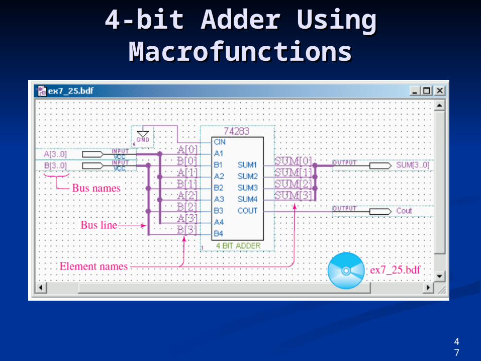
4-bit Adder Using 4-bit Adder Using MacrofunctionsMacrofunctions
47
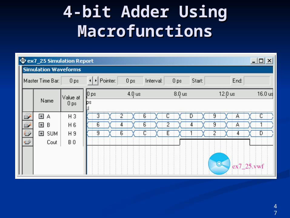
4-bit Adder Using 4-bit Adder Using MacrofunctionsMacrofunctions
47
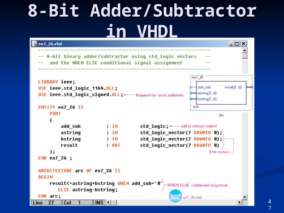
8-Bit Adder/Subtractor in 8-Bit Adder/Subtractor in VHDLVHDL
47
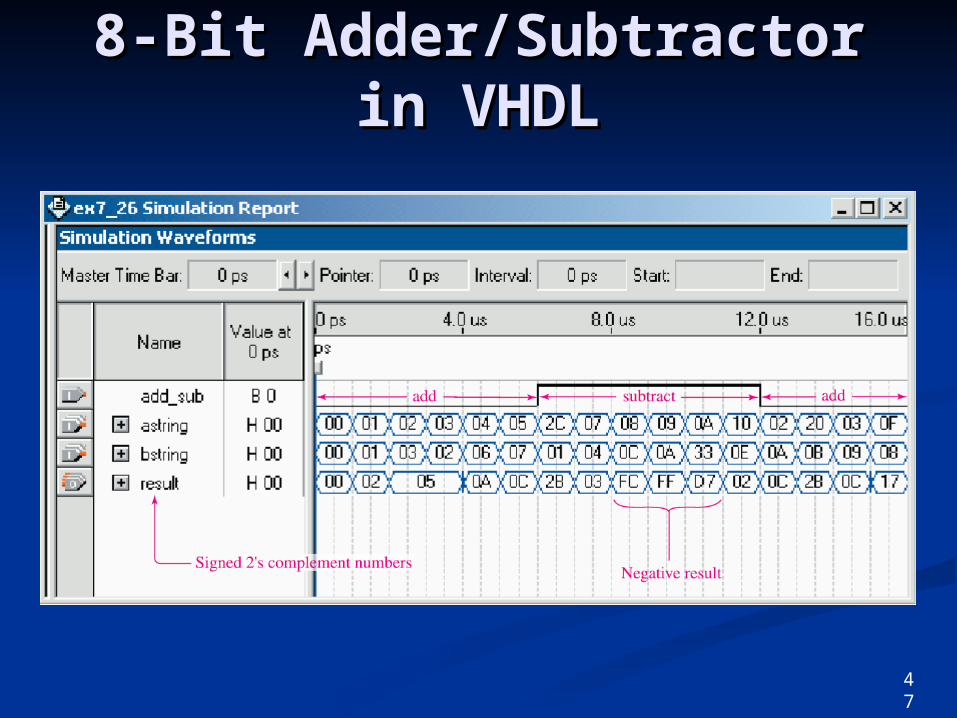
8-Bit Adder/Subtractor in 8-Bit Adder/Subtractor in VHDLVHDL
47
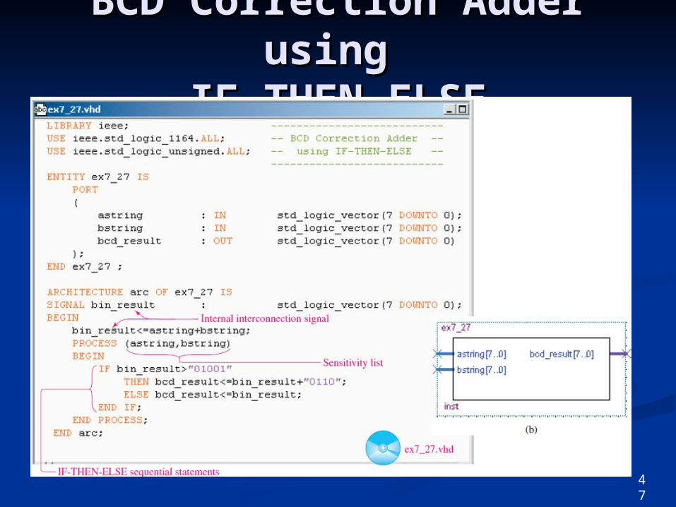
BCD Correction Adder BCD Correction Adder using using
IF-THEN-ELSEIF-THEN-ELSE
47
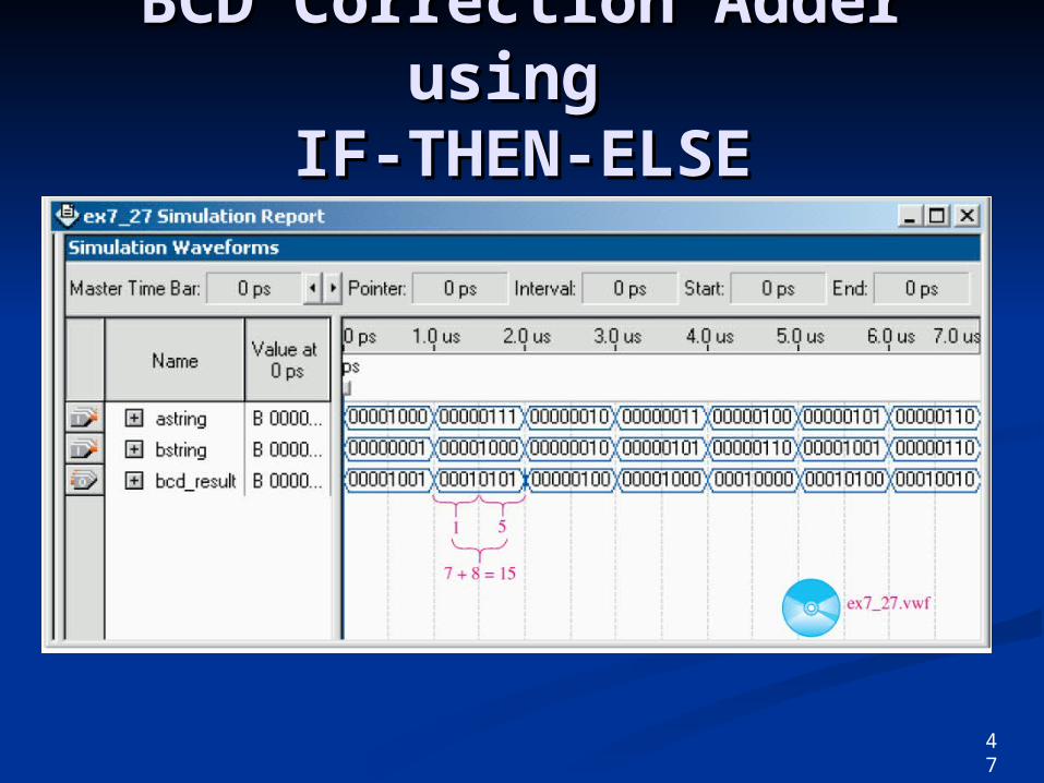
BCD Correction Adder BCD Correction Adder using using
IF-THEN-ELSEIF-THEN-ELSE
47
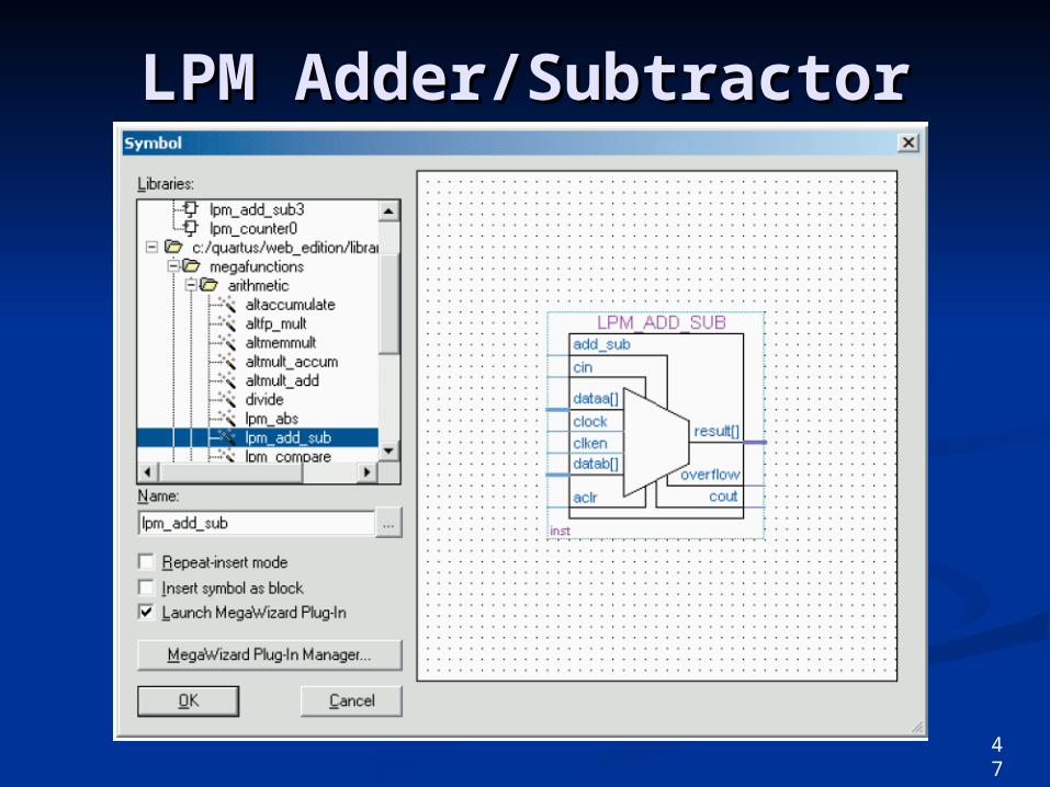
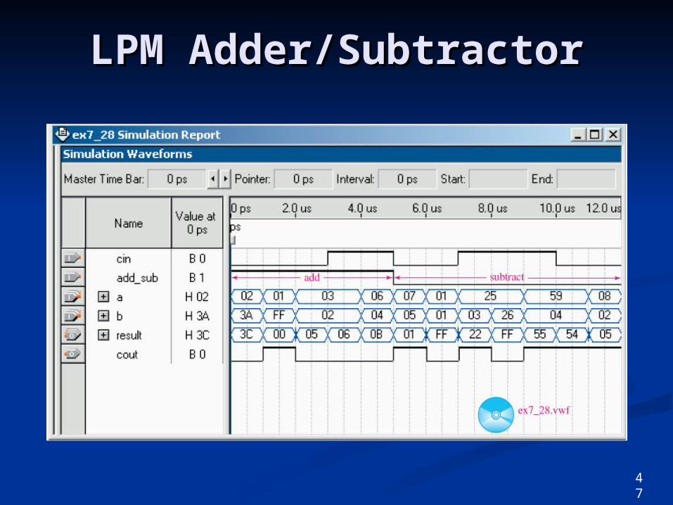
LPM Adder/SubtractorLPM Adder/Subtractor
47
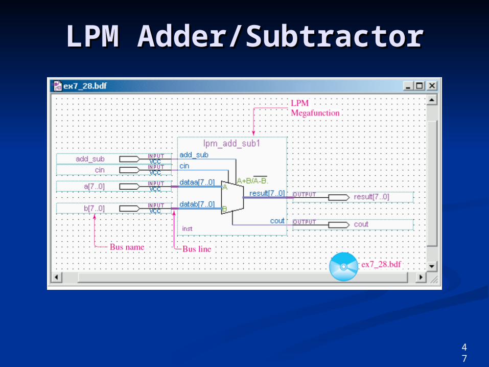
LPM Adder/SubtractorLPM Adder/Subtractor
47
LPM Adder/SubtractorLPM Adder/Subtractor
SummarySummary
The binary arithmetic functions of The binary arithmetic functions of addition, subtraction, multiplication, addition, subtraction, multiplication, and division can be performed bit-by-and division can be performed bit-by-bit using several of the same rules of bit using several of the same rules of regular base 10 arithmetic.regular base 10 arithmetic.
The two’s-complement representation The two’s-complement representation of binary numbers is commonly used of binary numbers is commonly used by computer systems for representing by computer systems for representing positive and negative numbers.positive and negative numbers.
48
SummarySummary
Two’s-complement arithmetic Two’s-complement arithmetic simplifies the process of subtraction of simplifies the process of subtraction of binary numbers.binary numbers.
Hexadecimal addition and subtraction Hexadecimal addition and subtraction is often required for determining is often required for determining computer memory space and locations.computer memory space and locations.
When performing BCD addition a When performing BCD addition a correction must be made for sums correction must be made for sums greater than 9 or when a carry to the greater than 9 or when a carry to the next more significant digit occurs.next more significant digit occurs.
49
SummarySummary
Binary adders can be built using Binary adders can be built using simple combinational logic circuits.simple combinational logic circuits.
A half-adder is required for addition A half-adder is required for addition of the least significant bitsof the least significant bits
A full-adder is required for addition A full-adder is required for addition of the more significant bits.of the more significant bits.
50
SummarySummary
Multibit full-adder ICs are commonly Multibit full-adder ICs are commonly used for binary addition and two’s-used for binary addition and two’s-complement arithmetic.complement arithmetic.
Arithmetic/logic units are multipurpose Arithmetic/logic units are multipurpose ICs capable of providing several ICs capable of providing several different arithmetic and logic functions.different arithmetic and logic functions.
The logic circuits for adders can be The logic circuits for adders can be described in VHDL using integer described in VHDL using integer arithmetic.arithmetic.
51
SummarySummary
The Quartus II software provides The Quartus II software provides 7400-series macrofunctions and a 7400-series macrofunctions and a Library of Parameterized Modules Library of Parameterized Modules (LPMs) to ease in the design of (LPMs) to ease in the design of complex digital systems.complex digital systems.
Conditional assignments can be Conditional assignments can be made using the IF-THEN-ELSE made using the IF-THEN-ELSE VHDL statements.VHDL statements.
51