Embed Size (px)
Citation preview
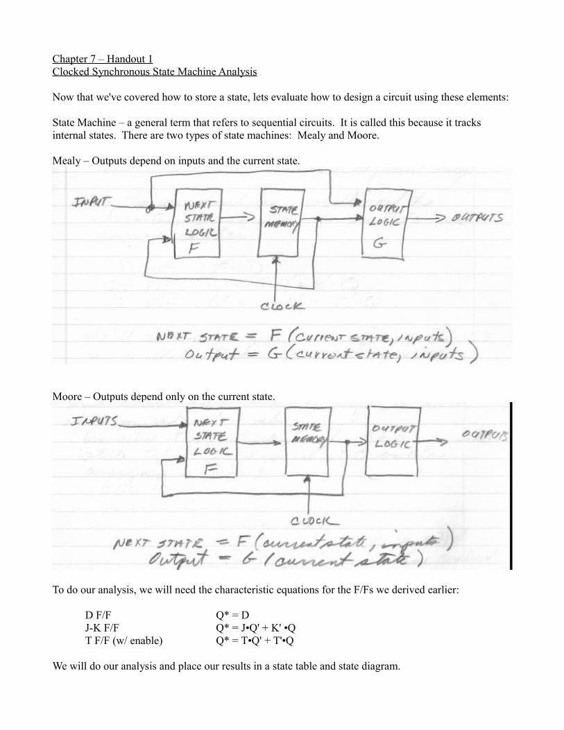
Chapter 7 – Handout 1Clocked Synchronous State Machine Analysis
Now that we've covered how to store a state, lets evaluate how to design a circuit using these elements:
State Machine – a general term that refers to sequential circuits. It is called this because it tracks internal states. There are two types of state machines: Mealy and Moore.
Mealy – Outputs depend on inputs and the current state.
Moore – Outputs depend only on the current state.
To do our analysis, we will need the characteristic equations for the F/Fs we derived earlier:
D F/F Q* = DJ-K F/F Q* = J•Q' + K' •QT F/F (w/ enable) Q* = T•Q' + T'•Q
We will do our analysis and place our results in a state table and state diagram.
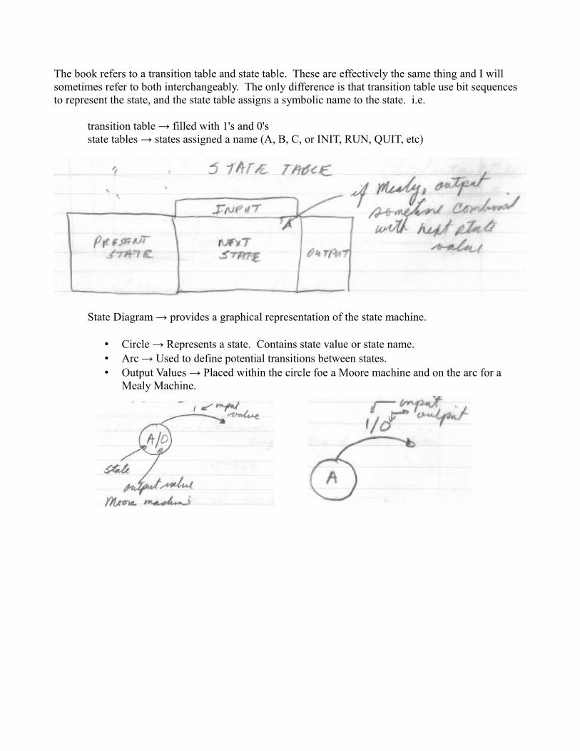
The book refers to a transition table and state table. These are effectively the same thing and I will sometimes refer to both interchangeably. The only difference is that transition table use bit sequences to represent the state, and the state table assigns a symbolic name to the state. i.e.
transition table → filled with 1's and 0'sstate tables → states assigned a name (A, B, C, or INIT, RUN, QUIT, etc)
State Diagram → provides a graphical representation of the state machine.
• Circle → Represents a state. Contains state value or state name.• Arc → Used to define potential transitions between states.• Output Values → Placed within the circle foe a Moore machine and on the arc for a
Mealy Machine.
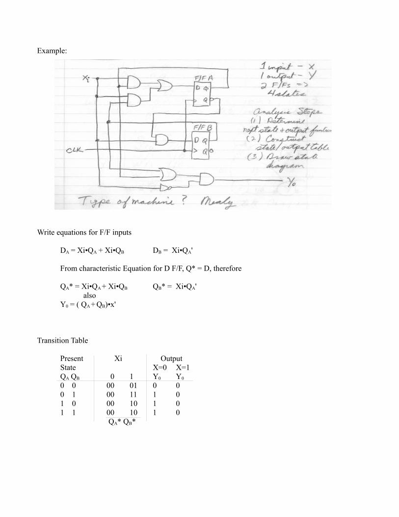
Example:
Write equations for F/F inputs
DA = Xi•QA + Xi•QB DB = Xi•QA'
From characteristic Equation for D F/F, Q* = D, therefore
QA* = Xi•QA + Xi•QB QB* = Xi•QA'also
Y0 = ( QA + QB)•x'
Transition Table
Present Xi OutputState X=0 X=1QA QB 0 1 Y0 Y0
0 0 00 01 0 00 1 00 11 1 01 0 00 10 1 01 1 00 10 1 0
QA* QB*
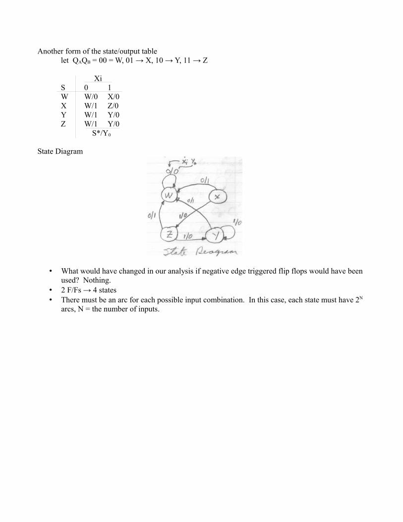
Another form of the state/output tablelet QAQB = 00 = W, 01 → X, 10 → Y, 11 → Z
XiS 0 1W W/0 X/0X W/1 Z/0Y W/1 Y/0Z W/1 Y/0
S*/Y0
State Diagram
• What would have changed in our analysis if negative edge triggered flip flops would have been used? Nothing.
• 2 F/Fs → 4 states• There must be an arc for each possible input combination. In this case, each state must have 2N
arcs, N = the number of inputs.
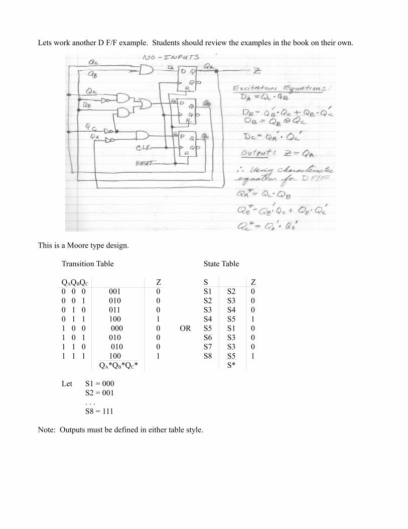
Lets work another D F/F example. Students should review the examples in the book on their own.
This is a Moore type design.
Transition Table State Table
QAQBQC Z S Z0 0 0 001 0 S1 S2 00 0 1 010 0 S2 S3 00 1 0 011 0 S3 S4 00 1 1 100 1 S4 S5 11 0 0 000 0 OR S5 S1 01 0 1 010 0 S6 S3 01 1 0 010 0 S7 S3 01 1 1 100 1 S8 S5 1
QA*QB*QC* S*
Let S1 = 000 S2 = 001. . .S8 = 111
Note: Outputs must be defined in either table style.
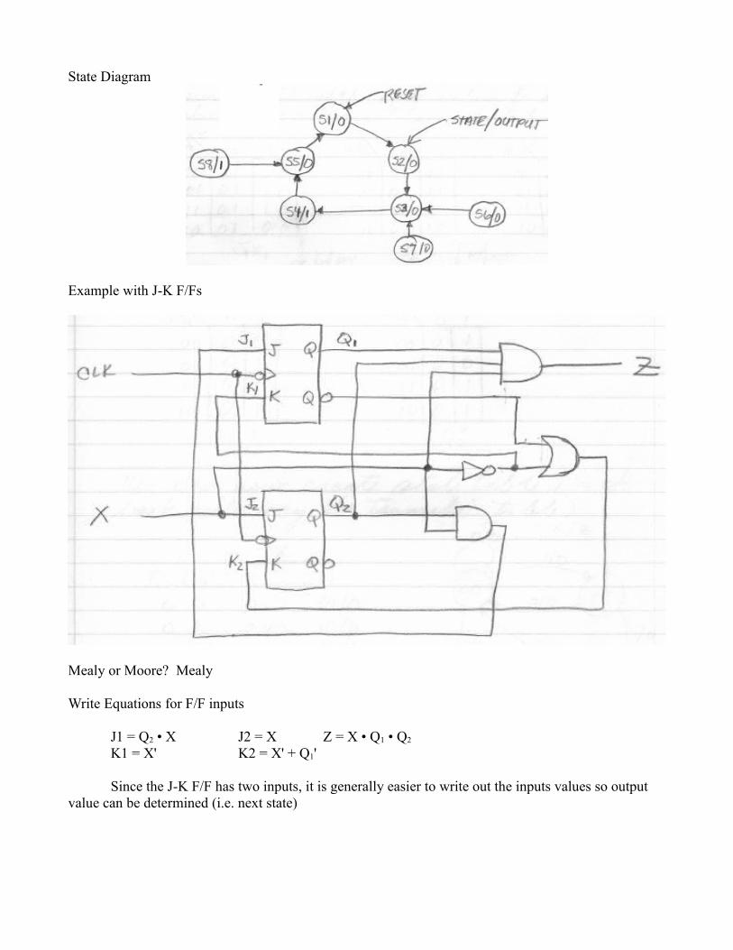
State Diagram
Example with J-K F/Fs
Mealy or Moore? Mealy
Write Equations for F/F inputs
J1 = Q2 • X J2 = X Z = X • Q1 • Q2
K1 = X' K2 = X' + Q1'
Since the J-K F/F has two inputs, it is generally easier to write out the inputs values so output value can be determined (i.e. next state)
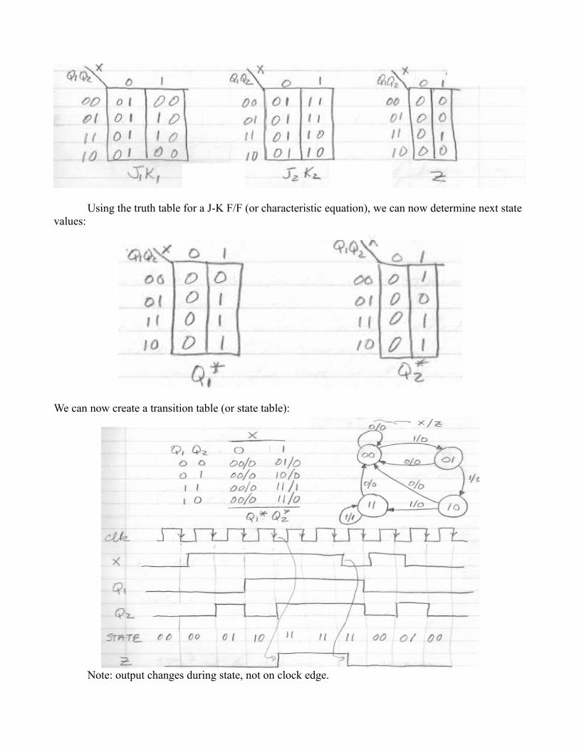
Using the truth table for a J-K F/F (or characteristic equation), we can now determine next state values:
We can now create a transition table (or state table):
Note: output changes during state, not on clock edge.

Now lets look at the general process for designing a sequential circuit to meet a set of requirements:
1. Get the specification → This can be the hardest part!2. Determine the state table/state diagram3. Choose state assignments
◦ Choose initial code that can easily forced by a reset (i.e. 000 or 111)◦ Minimize the number of state variables that change between each transition.◦ Maximize the number of state variables that don't change in a group of related states ( a
group of states where most transitions stay in the group).◦ Exploit symmetries in the problem specification and the corresponding symmetries in the
state table. (i.e. one state or group means almost the same thing as another. Once the first group has an assignment, the second group should have a similar assignment.)
◦ If there are unused states, the choose the best subset to meet the previous goals.Decompose the set of state variables into individual bits or fields, where each bit or field has a well defined meaning with respect to inputs or output behavior
◦ Consider using more than the minimum number of state variables to make a decomposed assignment possible.
◦ See p 561 for a deeper explanation.4. Choose F/F type5. Generate Excitation maps which allow you to derive input equations6. Sketch the circuit.
Lets start off with a simple example of an up/down counter using all 3 F/F types:
One input: X 0 count down (3-->2-->1-->0-->3, etc)1 count up (0-->1-->2-->3-->0, etc)
Outputs: Count value (0 or 1 or 2 or 3)Z – min/max value
X = 0, Z = 1 when count is 0, 0 otherwiseX = 1, Z = 1 when count is 3, 0 otherwise
Start off by drawing the state diagram
Since we want to output the count, we will let the state value also serve as the count output. Using 2 F/Fs (F/F1 and F/F0) with outputs Q1 and Q0, the state assignments are as follows:
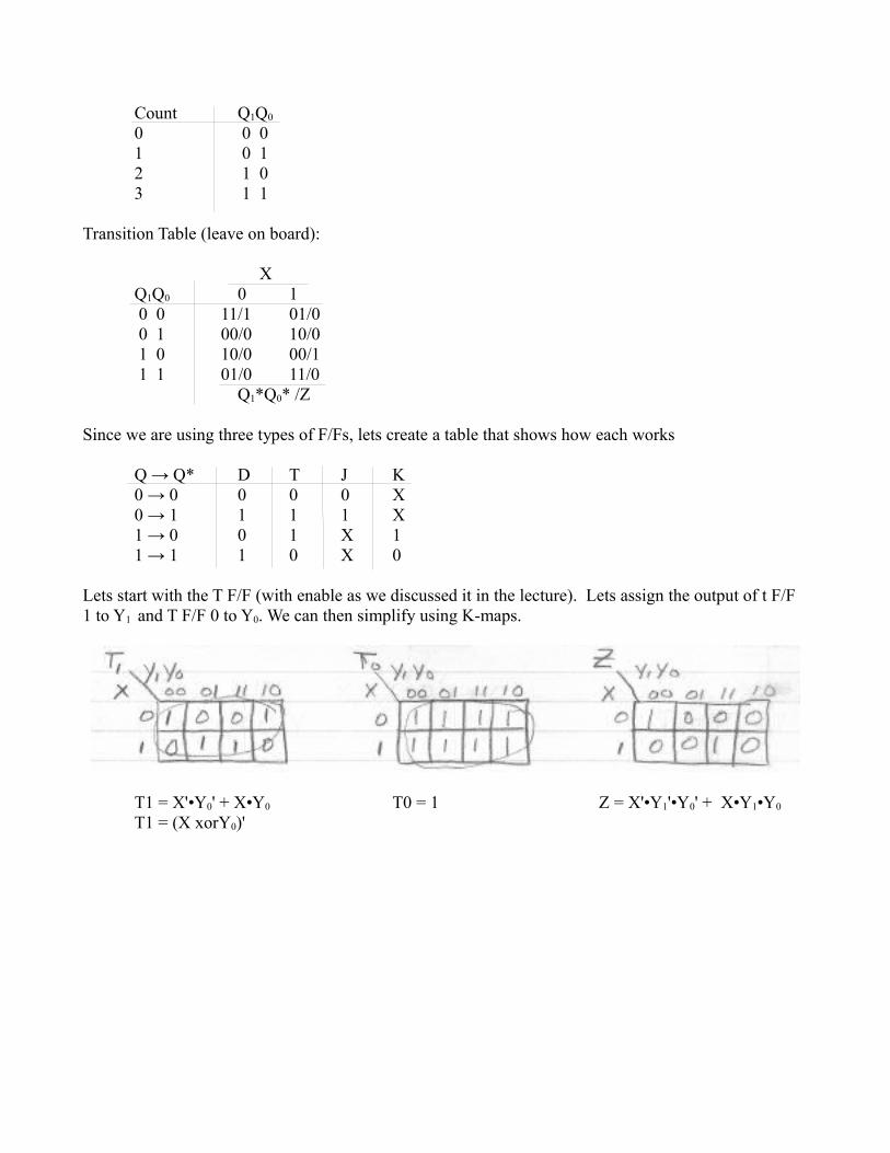
Count Q1Q0
0 0 01 0 12 1 03 1 1
Transition Table (leave on board):
XQ1Q0 0 1 0 0 11/1 01/0 0 1 00/0 10/0 1 0 10/0 00/1 1 1 01/0 11/0
Q1*Q0* /Z
Since we are using three types of F/Fs, lets create a table that shows how each works
Q → Q* D T J K0 → 0 0 0 0 X0 → 1 1 1 1 X1 → 0 0 1 X 11 → 1 1 0 X 0
Lets start with the T F/F (with enable as we discussed it in the lecture). Lets assign the output of t F/F 1 to Y1 and T F/F 0 to Y0. We can then simplify using K-maps.
T1 = X'•Y0' + X•Y0 T0 = 1 Z = X'•Y1'•Y0' + X•Y1•Y0
T1 = (X xorY0)'
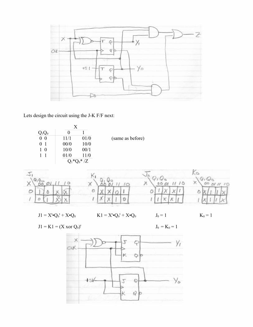
Lets design the circuit using the J-K F/F next:
XQ1Q0 0 1 0 0 11/1 01/0 (same as before) 0 1 00/0 10/0 1 0 10/0 00/1 1 1 01/0 11/0
Q1*Q0* /Z
J1 = X'•Q0' + X•Q0 K1 = X'•Q0' + X•Q0 J0 = 1 K0 = 1
J1 = K1 = (X xor Q0)' J0 = K0 = 1
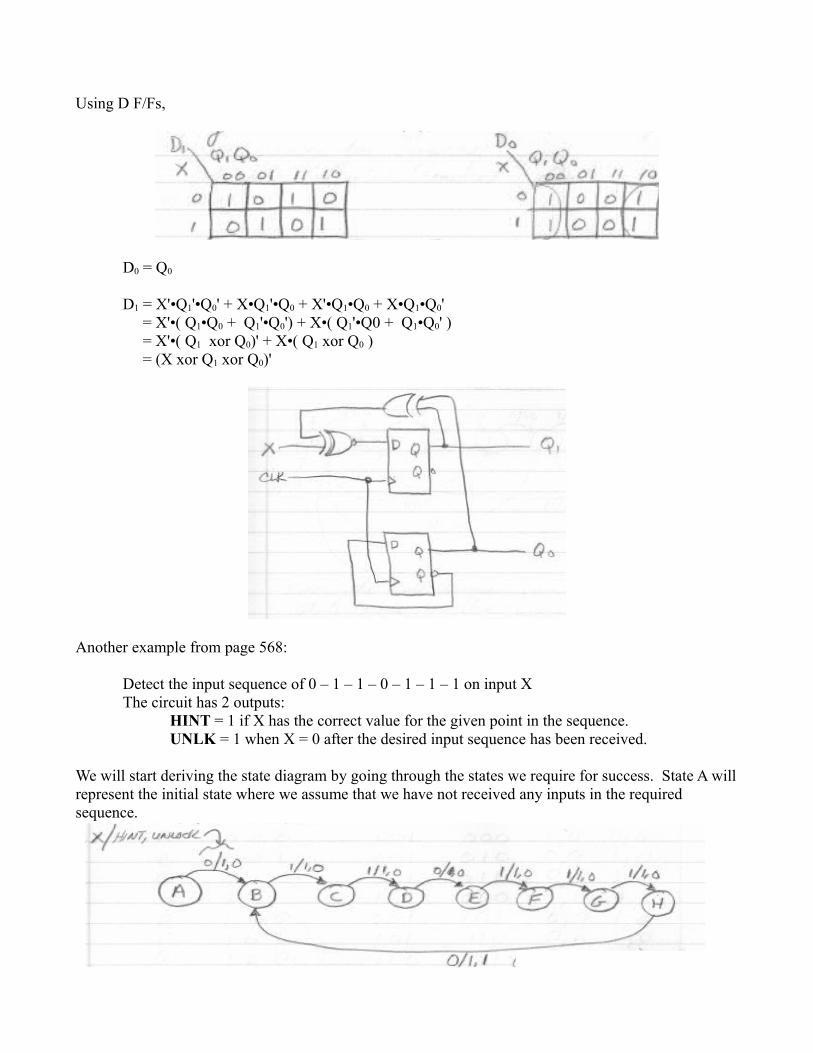
Using D F/Fs,
D0 = Q0
D1 = X'•Q1'•Q0' + X•Q1'•Q0 + X'•Q1•Q0 + X•Q1•Q0' = X'•( Q1•Q0 + Q1'•Q0') + X•( Q1'•Q0 + Q1•Q0' ) = X'•( Q1 xor Q0)' + X•( Q1 xor Q0 ) = (X xor Q1 xor Q0)'
Another example from page 568:
Detect the input sequence of 0 – 1 – 1 – 0 – 1 – 1 – 1 on input XThe circuit has 2 outputs:
HINT = 1 if X has the correct value for the given point in the sequence. UNLK = 1 when X = 0 after the desired input sequence has been received.
We will start deriving the state diagram by going through the states we require for success. State A will represent the initial state where we assume that we have not received any inputs in the required sequence.
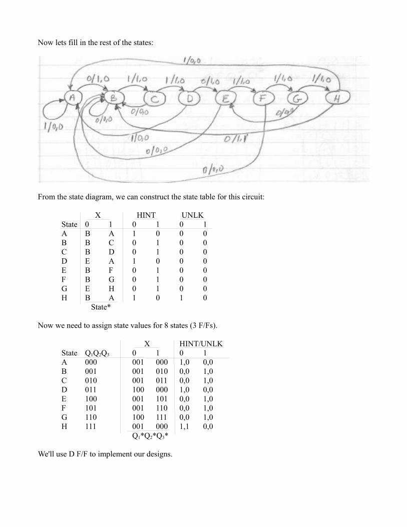
Now lets fill in the rest of the states:
From the state diagram, we can construct the state table for this circuit:
X HINT UNLKState 0 1 0 1 0 1A B A 1 0 0 0B B C 0 1 0 0C B D 0 1 0 0D E A 1 0 0 0E B F 0 1 0 0F B G 0 1 0 0G E H 0 1 0 0H B A 1 0 1 0
State*
Now we need to assign state values for 8 states (3 F/Fs).
X HINT/UNLKState Q1Q2Q3 0 1 0 1A 000 001 000 1,0 0,0B 001 001 010 0,0 1,0C 010 001 011 0,0 1,0D 011 100 000 1,0 0,0E 100 001 101 0,0 1,0F 101 001 110 0,0 1,0G 110 100 111 0,0 1,0H 111 001 000 1,1 0,0
Q1*Q2*Q3*
We'll use D F/F to implement our designs.
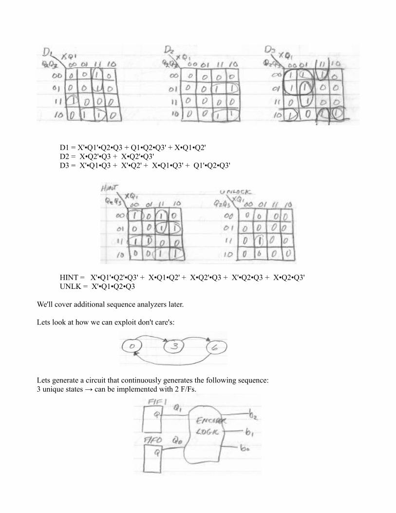
D1 = X'•Q1'•Q2•Q3 + Q1•Q2•Q3' + X•Q1•Q2'D2 = X•Q2'•Q3 + X•Q2'•Q3'D3 = X'•Q1•Q3 + X'•Q2' + X•Q1•Q3' + Q1'•Q2•Q3'
HINT = X'•Q1'•Q2'•Q3' + X•Q1•Q2' + X•Q2'•Q3 + X'•Q2•Q3 + X•Q2•Q3'UNLK = X'•Q1•Q2•Q3
We'll cover additional sequence analyzers later.
Lets look at how we can exploit don't care's:
Lets generate a circuit that continuously generates the following sequence:3 unique states → can be implemented with 2 F/Fs.
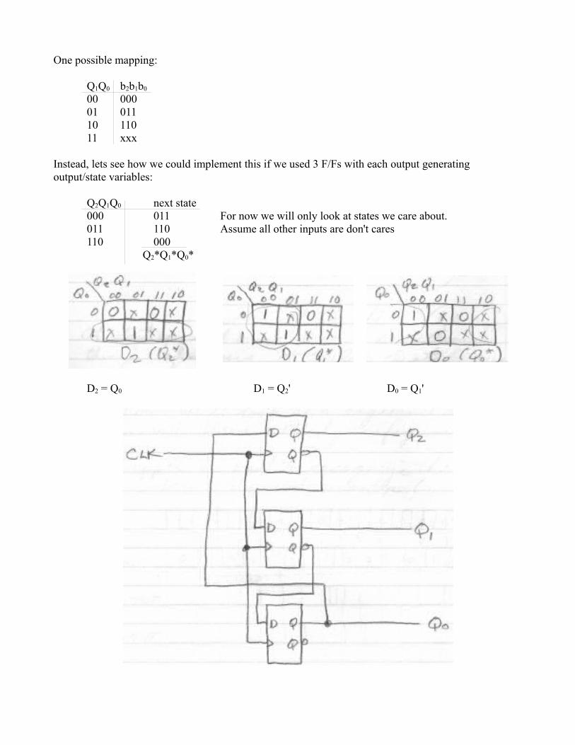
One possible mapping:
Q1Q0 b2b1b0
00 00001 01110 11011 xxx
Instead, lets see how we could implement this if we used 3 F/Fs with each output generating output/state variables:
Q2Q1Q0 next state000 011 For now we will only look at states we care about.011 110 Assume all other inputs are don't cares110 000
Q2*Q1*Q0*
D2 = Q0 D1 = Q2' D0 = Q1'
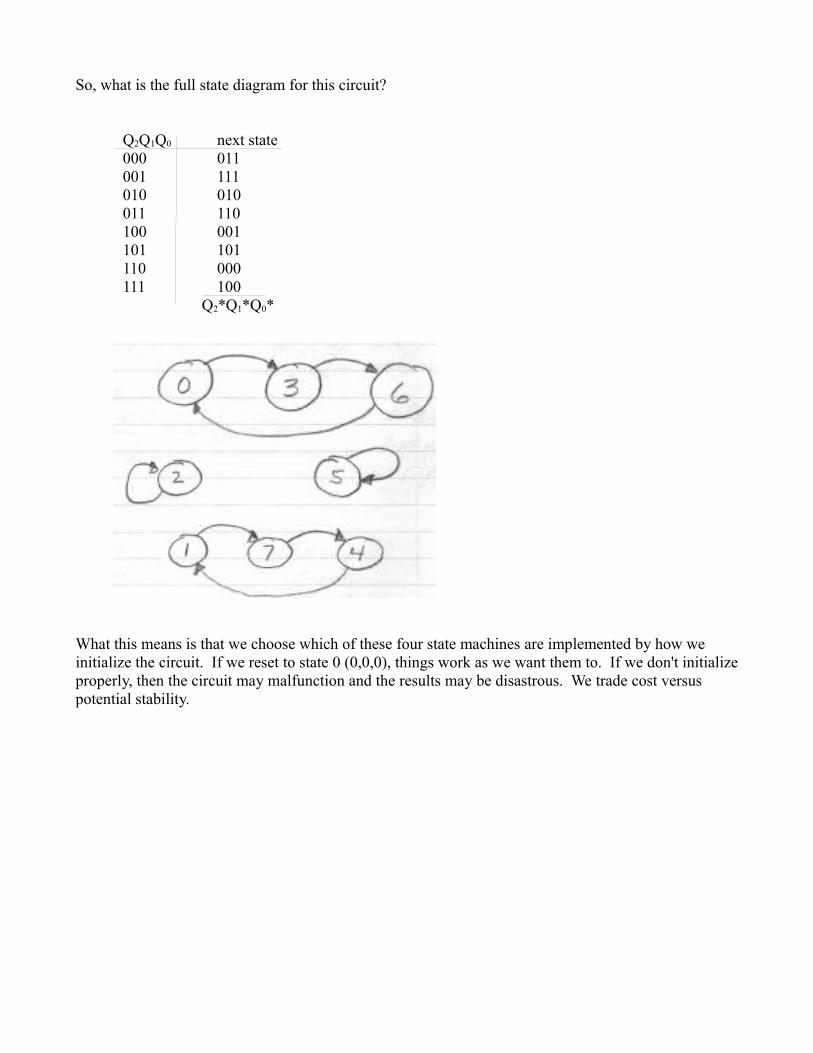
So, what is the full state diagram for this circuit?
Q2Q1Q0 next state000 011001 111010 010011 110100 001101 101110 000 111 100
Q2*Q1*Q0*
What this means is that we choose which of these four state machines are implemented by how we initialize the circuit. If we reset to state 0 (0,0,0), things work as we want them to. If we don't initialize properly, then the circuit may malfunction and the results may be disastrous. We trade cost versus potential stability.