Embed Size (px)
Citation preview

CHAPTER 7 7.1 AIR-CONDITIONING & MECHANICAL VENTILATION SYSTEMS 7.1.1 General
(a) Where air-conditioning system is provided in lieu of mechanical ventilation system during
emergency, all the requirements specified in this Code for the mechanical ventilation system shall apply to the air-conditioning system.
EXPLANATIONS & ILLUSTRATIONS
No illustration.
The term “air conditioning” has been defined by the American Society of Heating, Refrigerating, and Air Conditioning Engineers as: “Air conditioning is the process of treating air so as to control simultaneously its temperature, humidity, cleanliness and distribution to meet the requirements of the conditioned space” The use of air conditioning and mechanical ventilation systems will invariably, except for self-contained split units, involve some use of pipe works and ducts for air distribution and removal. The use of ducts present the inherent possibility of spreading fire, heat, gases and smoke throughout the building or the floors/areas served.
Where air conditioning system is designed to operate during fire emergency, it is to be emphasized that the system shall comply with all the relevant requirements for the mechanical ventilation system in this Code.
(b) Construction of ductwork
Ducts for air-conditioning and mechanical ventilation systems shall be constructed in compliance with the following requirements: (i) All air-conditioning or other ventilation ducts including framing thereof, shall be
constructed of steel, aluminium, glass-fibrebatt or mineral-wool batt or other approved material.
(ii) All air-conditioning or other ventilation ducts shall be adequately supported. (iii) Duct covering and lining should be non-combustible. However, if it is necessary to
use combustible material, it shall:-
(1) when tested in accordance with methods specified in this Code, have a surface flame spread rating of not lower than Class 1, but in areas of building where Class 0 flame spreading rating is required for the ceiling construction under this Code, a Class 0 rating for the covering and lining materials shall be required;
(2) when involved in fire generate a minimum amount of smoke and toxic gases; and
(3) be at least 1m away from a fire damper. (iv) Flexible joint and connection
Flexible connections at the extremity of ventilation ductwork connecting terminal units, extract units and ventilation grilles shall not exceed 4m. Flexible joints, which are normally provided to prevent and/or allow for thermal movements in the duct system, shall not exceed 250mm in length. Flexible joints shall be made of material classified as ‘not easily ignitable’ when tested under BS 476: Part 5.

EXPLANATIONS & ILLUSTRATIONS 7.1.1(b)
Diagram 7.1.1(b)
Minimum Class1 for insulation material/barrier lining and adhesives. Where ceiling construction requires class 0, covering and lining insulation material shall also be class 0. Where combustible material is used for the insulation of the duct, it shall be kept at least 1000mm away from a fire damper in order to prevent premature closing of the damper arising from a fire from the combustible insulation material. For flexible joints and connections which are combustible, there is a need to limit the length of the joints and connection to max. 250mm and 4m respectively.

(c) Pipework insulation
Insulation for pipework associated with the air-conditioning and mechanical ventilation systems shall comply with the following requirements: (i) Insulation material for pipework together with vapour barrier lining and adhesives
shall when tested in accordance with the methods specified in this Code, have a surface flame spread of not lower than Class 1 but in areas of buildings where Class 0 flame spread is required for the ceiling construction under this Code, a Class 0 rating for the insulation material shall be required.
(ii) Plastic and foam rubber insulation
Notwithstanding the requirements of sub-clause (c)(i), the use of plastic and foam rubber insulation materials of a lower classification may be permissible if: (1) the material is the self-extinguishing type acceptable to the Relevant Authority;
(2) the insulation material is covered by or encased in a metal sheath or hybrid
plaster or other non-combustible cladding materials acceptable to the Relevant Authority.
Provided that any opening in the element of structure or other part of a building penetrated by the pipework shall be effectively fire-stopped by replacement of the insulation material at the junction of penetration with fire resistant material having equal fire rating. Fire rated proprietary pipework system may be used if it is tested in the manner acceptable to the Relevant Authority.
EXPLANATIONS & ILLUSTRATIONS 7.1.1
Diagram 7.1.1(c)-1

EXPLANATIONS & ILLUSTRATIONS 7.1.1(c)
Diagram 7.1.1(c)-2
Diagram 7.1.1(c)-3
Minimum class 1 for insulation material/barrier lining and adhesives. Where ceiling construction requires class 0, insulation material shall also be class 0. However, the use of 10mm to 15mm max. pipe works for split unit system would be considered as acceptable. The use of fire collar shall be appropriate for the diameter of the PVC/UPVC pipe and shall be duly secured to the surface of the wall or floor with steel anchor bolts.

(d) Duct enclosure
Enclosure of ducts shall comply with the requirements in sub-clause 3.8.9(a).
EXPLANATIONS & ILLUSTRATIONS 7.1.1
No illustration.
“A protected shaft used for the enclosure of services shall comply with the following: (a) The protecting structure for protected shaft containing kitchen exhaust duct and mechanical
ventilation ducts serving areas specified in Cl. 5.2.1(g)(i) to (iii) and (h) which pass through one or more floors shall be masonry. Such shaft shall be completely compartmented from the rest of the shaft space containing other ducts or any other services installations. For protected shaft containing ducts serving other areas which pass through two or more floors shall be of fire rated material.

(e) Ductwork through smoke-stop or fire-fighting lobbies
Ventilation ducts should not pass through smoke-stop or fire fighting lobby. Where unavoidable, the part of the ventilation duct within the lobby shall be enclosed in construction with fire resistance rating at least equal to that of the elements of structure. Such construction shall be in masonry. If other form of fire resisting construction is used, fire damper shall be fitted where the duct penetrates the lobby enclosure.
EXPLANATIONS & ILLUSTRATIONS 7.1.1
Diagram 7.1.1(e)-1
In addition to providing fire rated enclosure to the duct within the lobby, fire damper is fitted where the duct penetrates the lobby enclosure. Should a fire penetrates the fire damper, it will still be contained within the duct.
EXPLANATIONS & ILLUSTRATIONS 7.1.1(e)
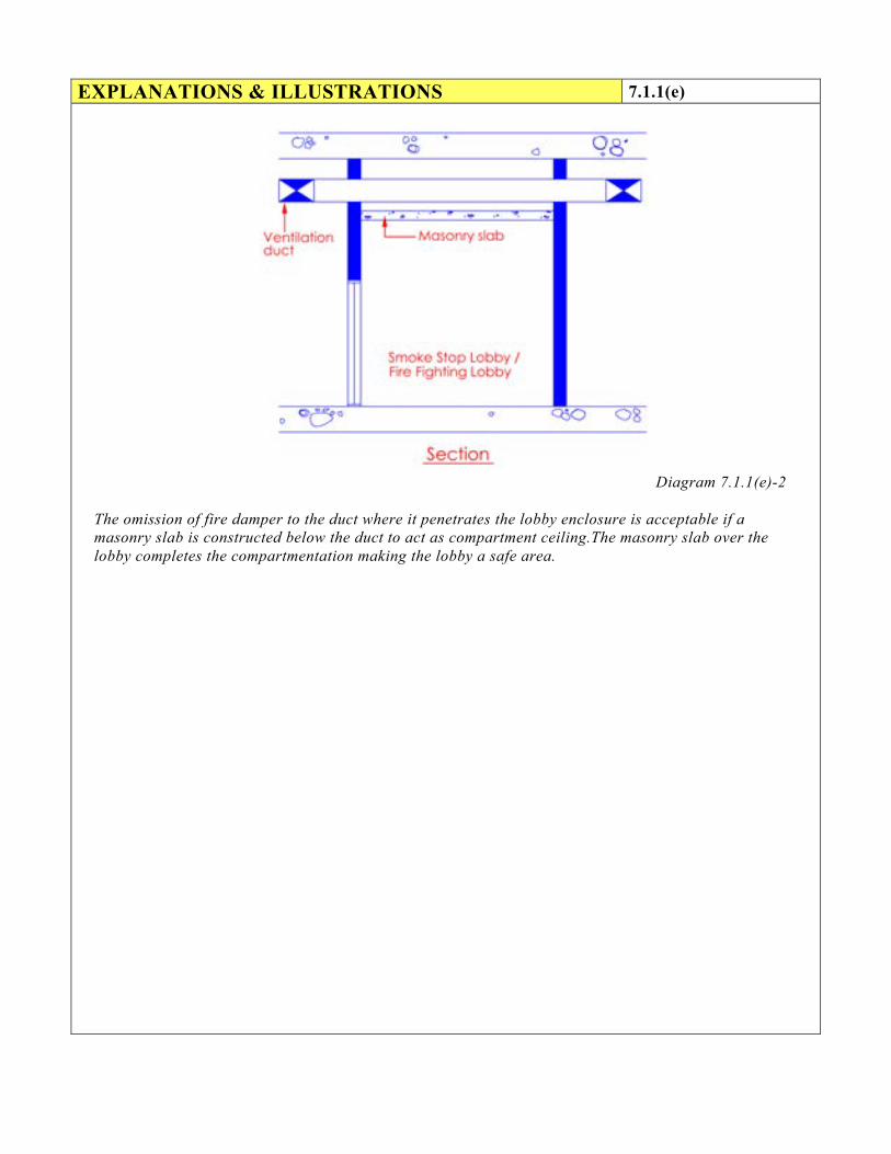
Diagram 7.1.1(e)-2
The omission of fire damper to the duct where it penetrates the lobby enclosure is acceptable if a masonry slab is constructed below the duct to act as compartment ceiling.The masonry slab over the lobby completes the compartmentation making the lobby a safe area.

EXPLANATIONS & ILLUSTRATIONS 7.1.1(e)
Ventilation ducts are routed from The AHU Rooms directly into the office space
Diagram 7.1.1(e)-3
With proper pre-planning, ventilation ducts are routed directly from the AHU rooms to occupancy areas, thus avoiding the routing through the protected lobby.

EXPLANATIONS & ILLUSTRATIONS 7.1.1(e)
Ventilation ducts are routed along protected lobby
Diagram 7.1.1(e)-4
Ventilation ducts are routed along the Smoke Stop Lobby to serve Office 2 & 3. Routing the ventilation ducts through the fire lift or smoke stop lobbies should be avoided. “Unavoidable situations” where ventilation ducts were routed through the fire lift or smoke stop lobbies referred to existing building where physical constraints existed making it difficult to route the ventilation duct through other spaces other than the lobby area.

(f) Plenum
A concealed space between the ceiling and floor above it, ceiling and roof, or raised floor and structural floor of a building can be used as a plenum provided that- (i) The concealed space contains only:
(1) mineral-insulated metal-sheathed cable, aluminium-sheathed cable,
copper-sheathed cable, rigid metal conduit, enclosed metal trunking, flexible metal conduit, liquid-tight flexible metal conduit in lengths not more than 2m, or metal-clad cables;
(2) electric equipment that is permitted within the concealed spaces of such structures if the wiring materials, including fixtures, are suitable for the expected ambient temperature to which they will be subjected;
(3) other ventilation ducts complying with sub-cl. (b);
(4) communication cables for computers, television, telephone and
inter-communication system;
(5) fire protection installations;
(6) pipes of non-combustible material conveying non-flammable liquids
(ii) The supports for the ceiling membrane are of non-combustible material.
(iii) Exception
Low-smoke and low-flame plenum rated PVC cables conforming to NFPA 262 are permitted to be run exposed in plenum, provided that : (1) The plenum space shall be protected by sprinkler system or gaseous total
flooding system.
(2) FCU or AHU using plenum for air return and serving more than one rooms, shall be provided with smoke detector at the return air plenum space to shut down the FCU/AHU on detection of smoke.
EXPLANATIONS & ILLUSTRATIONS 7.1.1(f)
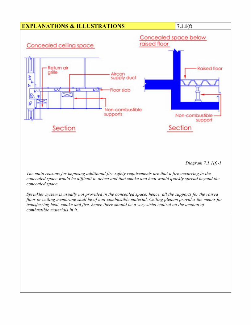
Diagram 7.1.1(f)-1
The main reasons for imposing additional fire safety requirements are that a fire occurring in the concealed space would be difficult to detect and that smoke and heat would quickly spread beyond the concealed space. Sprinkler system is usually not provided in the concealed space, hence, all the supports for the raised floor or ceiling membrane shall be of non-combustible material. Ceiling plenum provides the means for transferring heat, smoke and fire, hence there should be a very strict control on the amount of combustible materials in it.
EXPLANATIONS & ILLUSTRATIONS 7.1.1(f)
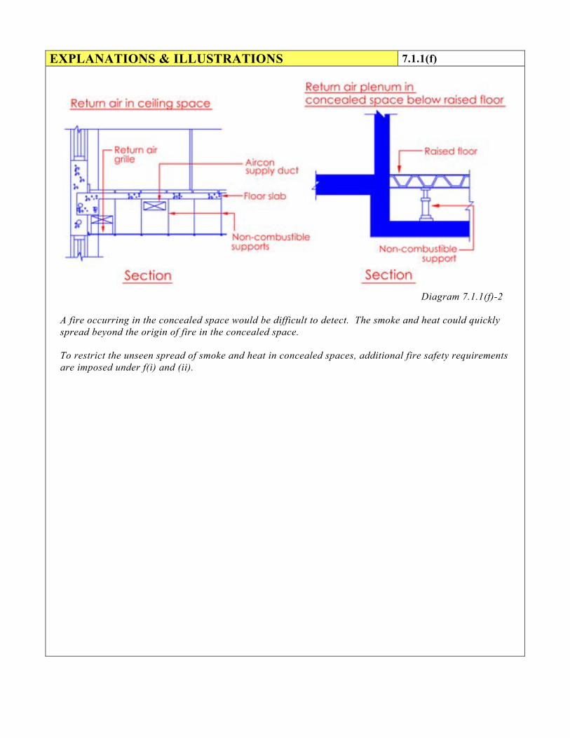
Diagram 7.1.1(f)-2
A fire occurring in the concealed space would be difficult to detect. The smoke and heat could quickly spread beyond the origin of fire in the concealed space.
To restrict the unseen spread of smoke and heat in concealed spaces, additional fire safety requirements are imposed under f(i) and (ii).

EXPLANATIONS & ILLUSTRATIONS 7.1.1(f)
Diagram 7.1.1(f)-3

EXPLANATIONS & ILLUSTRATIONS 7.1.1(f)
Diagram 7.1.1(f)-4
Low-flame and low-smoke plenum rated PVC cables conforming to NFPA 262 are permitted to be run exposed in plenum, provided that the plenum shall be protected by sprinkler system or gaseous total flooding system. In the case of Fan Coil Unit (FCU) or Air Handling Unit (AHU) using plenum for air return and serving more than one rooms, it shall be provided with smoke detection at the return air plenum. This is to address smoke detection within the air plenum space.

(g) Separating walls
No air conditioning or ventilation ducts shall penetrate separating walls.
EXPLANATIONS & ILLUSTRATIONS 7.1.1
Diagram 7.1.1(g)-1
A separating wall is a division wall that separate adjoining buildings of different ownership. Ducts are prohibited to penetrate separating wall to prevent fire spread from one building to another.

EXPLANATIONS & ILLUSTRATIONS 7.1.1(g)
Diagram 7.1.1(g)-2
In terrace shophouses, there should be no sharing of air-con ducts.

(h) Fire Dampers
Any fire damper shall have a fire resistance rating of not less than that required for the compartment wall or compartment floor through which the relevant section of the ventilation duct passes. Fire dampers shall be of the type approved by the relevant authority and constructed in accordance with the requirements in SS 333 - Specifications of fire dampers.
(i) Provision of fire dampers
Ventilation ducts which pass directly through a compartment wall or compartment floor shall comply with the following –
(1) where the ventilation duct does not form a protected shaft or is not contained within a protecting structure, the duct shall be fitted with a fire damper where it passes through the compartment wall or compartment floor;
(2) where the ventilation duct forms a protected shaft or is contained within a protecting structure, the duct shall be fitted with fire dampers at the inlets to the shaft and outlets from it.
EXPLANATIONS & ILLUSTRATIONS 7.1.1
Diagram 7.1.1(h)(i)-1
Exposed ventilation duct is not fire rated. Fire damper is provided where it passes through the compartment floor or wall to prevent fire spread from compartment to compartment via the duct.

EXPLANATIONS & ILLUSTRATIONS 7.1.1(h)
Diagram 7.1.1(h)(i)-2
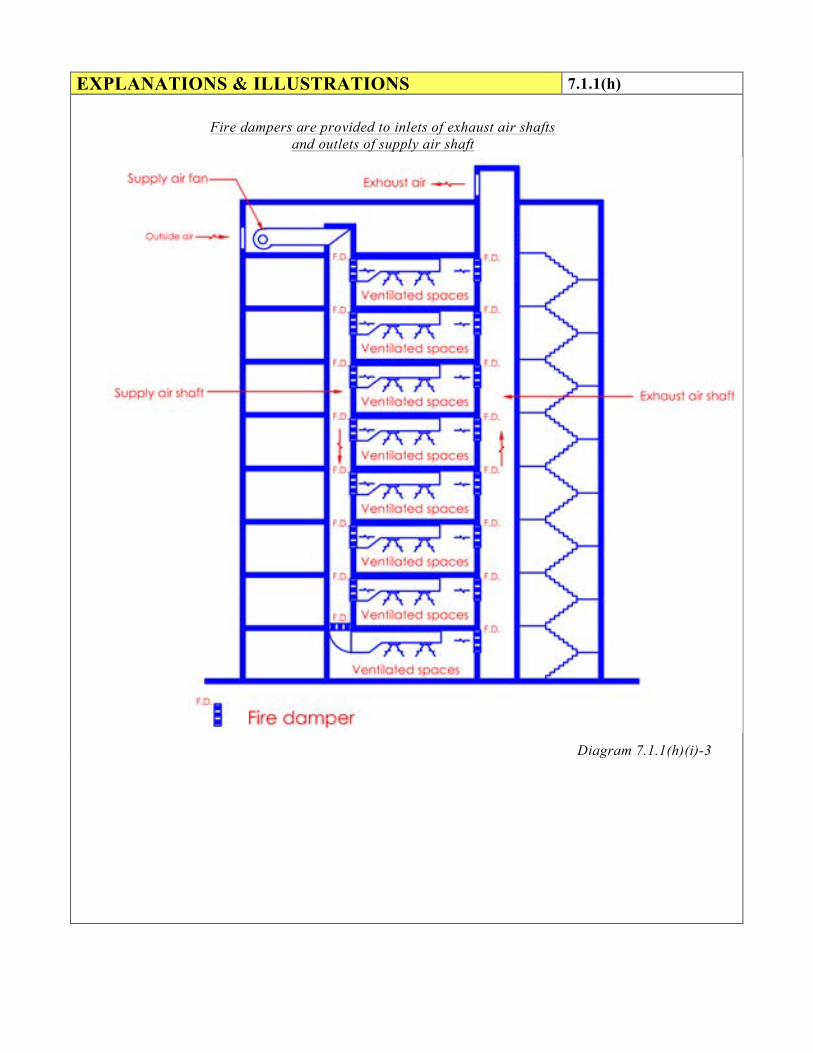
To prevent fire spread from compartment to compartment via the duct, fire damper shall be provided at the inlets to the exhaust air shaft and outlets from supply air shaft. The dampers shall be properly secured to the protecting structure or protected shaft to prevent any displacement. The method of installation shall follow the type tests shown in the test report issued by testing laboratory.
Ventilation duct contained within protected shaft Ventilation duct forms a
protected shaft
EXPLANATIONS & ILLUSTRATIONS 7.1.1(h)
Diagram 7.1.1(h)(i)-3
Fire dampers are provided to inlets of exhaust air shafts and outlets of supply air shaft

(ii) Installation of fire dampers
(1) Fire dampers shall be installed so that the casing completely penetrates through the compartment wall or floor and the casing shall be retained either:
* On both sides by means of flanges in such a manner that it can expand under fire conditions without distorting the blades in the closed position, or
* On the accessible side by means of one flange only, which can be fixed to the damper and to the wall through slotted holes to allow for expansion.
(2) Flanges shall be butted against the face of the compartment wall or floor and fixed to the damper casing.
(3) Ductwork connected to the damper shall be attached in such a manner as to ensure that the damper remains securely in position and is fully functional in the event of damage of ductwork.
(4) The clearance between the damper body and the sides of the penetration shall not be less than that of the tested prototype and not greater than half the width of the angle section of the collar.
(5) The space between the damper body and the opening in the wall or floor shall be fire-stopped.
(6) Vertically positioned fire dampers shall be installed in such a manner that the direction of air flow assists the closure of the damper.
(7) Connections to fire dampers
The distance between the plane through a closed fire damper and ducting, flexible connections, duct coverings, internal linings and the like, shall be:- * Not less than 1m when such parts are made of materials with fusing
temperatures less than 1000oC, and
* Not less than three times the diagonal or diameter of the damper and in no case less than 2m when such parts are made of materials that are combustible except for vapour barrier to thermal insulation.

(8) Access door in ventilation duct for inspection of fire damper
Each fire damper installation shall be provided with an inspection access door either upstream or downstream as appropriate. The access door dimension shall preferably measure 450mm (length) × 450mm (width); for smaller ducts, the door width dimension may be reduced to the width or depth of the duct. Access doors shall be hinged and fitted with sash locks, and constructed of minimum 1.25mm sheet steel suitably braced. Openings in ducts shall be stiffened by sheet steel frame.
EXPLANATIONS & ILLUSTRATIONS 7.1.1(h)(ii)
No illustration.

(iii) Prohibition of fire dampers
Fire dampers shall not be fitted in the following locations:
(1) openings in walls of a smoke extract shaft or return air shaft which also serves as a smoke extract shaft;
(2) openings in walls of a protected shaft when the openings have a kitchen exhaust duct passing through it; or
(3) anywhere in an air pressurising system;
(4) where explicitly prohibited in this Code.
EXPLANATIONS & ILLUSTRATIONS 7.1.1(h)
Diagram 7.1.1(h)(iii)
Fire dampers shall not be fitted in any of the supply air shaft or extract air shaft. The smoke purging system would fail as the fire dampers when in closed position would prevent movement of air within the shaft. Fire dampers shall not be provided in the following locations: a) openings in wall of a protected shaft serving kitchen exhaust;
b) anywhere in the supply duct work of air pressurising system to exit staircse; and
c) anywhere in the supply and exhaust ducts serving fire pump room, generator room, fire command
centre and flammable store.

(iv) Where a fire damper is required by this Code to be installed in the air-conditioning
and mechanical ventilation system, its type, details of installation, connection of accessories, inspection door, etc shall be in accordance with SS CP 333 Specifications of Fire Dampers
EXPLANATIONS & ILLUSTRATIONS 7.1.1(h)
No illustration.

(i) Fire resisting floor-ceiling and roof-ceiling
(1) The space above a suspended ceiling which forms part of a fire-rated floor ceiling or roof-ceiling construction shall not contain ducting unless ducting was incorporated in a prototype that qualified for the required fire-resistance rating, in which case the ducting shall be identical to that incorporated in the tested prototype.
EXPLANATIONS & ILLUSTRATIONS 7.1.1
Ducting above fire rated ceiling or roof ceiling construction
Diagram 7.1.1(i)(1)
Mechanical ventilation ducts are not permitted to be located in the concealed space of fire rated floor ceiling or roof ceiling assembly, unless such ducts are included in the prototype that was tested for the required fire resistance rating. The type of ducting within such ceiling or roof spaces as well as details of openings in such ceiling shall be identical to that incorporated in the tested prototype.

(2) Openings in the ceiling, including openings to enable the ceiling to be used as a plenum,
shall be protected by fire dampers identical to those used in the tested prototype and such openings in the ceiling shall be so arranged that -
(1) No opening is greater in area than that corresponding in the prototype test panel; (2) The aggregate area of the openings per unit ceiling area does not exceed that of
the prototype test panel; and
(3) The proximity of any opening to any structural member is not less than that in the prototype test panel.
EXPLANATIONS & ILLUSTRATIONS 7.1.1(i)(2)
.
Diagram 7.1.1(i)(2)
* Area of each opening (A & B) shall not be greater or larger than that in the prototype test panel. * Total area of openings (A &B) for ceiling to each compartment shall not be greater than that of the
prototype test panel. * The opening (A &B) may be relocated within the ceiling area provided the proximity to structural
member, eg. column, beams and structural walls is not less than that in the prototype test panel.

(j) Fire rated duct
(i) Where proprietary fire rated materials are used to construct the fire rated duct, the fire rating of the fire rated duct shall have the same period of fire resistance as the wall or floor it penetrates.
(ii) Proprietary fire rated duct shall be tested to BS 476 Pt 24 or equivalent and its usage be approved by the Relevant Authority
(iii) Running of non-fire rated duct and/or other building services above the proprietary fire rated duct should be avoided. When unavoidable due to physical constraints, the supports to such non-fire rated duct and/or other building services running above the proprietary fire rated duct shall be strengthened such that the tensile stress generated on the supports shall not exceed 10N/mm2 and the non-fire rated duct and/or building services shall also be adequately protected to prevent collapse in a fire which will otherwise affect the stability of the proprietary fire rated duct below.
(iv) Fans forming part of a fire rated duct shall also be enclosed in the same fire rated enclosure.
EXPLANATIONS & ILLUSTRATIONS 7.1.1
Diagram 7.1.1(j)(iii)

(k) Locations of intakes and return air openings
Openings for the intakes of outdoor air to all air handling systems, mechanical ventilation systems, pressurisation systems of exit staircases and internal corridors, and smoke control systems shall be no less than 5m from any exhaust discharge openings. All return air openings and outdoor air intakes shall be so located and arranged that sources of ignition such as lighted matches and cigarette butts accidentally entering the openings and intakes shall not be deposited onto the filter media.
EXPLANATIONS & ILLUSTRATIONS 7.1.1
No illustration.

CHAPTER 7 7.1 AIR-CONDITIONING & MECHANICAL VENTILATION SYSTEMS 7.1.2 Air handling unit room
(a) Air handling systems shall not use protected shaft of exits, smoke-stop lobbies, including
its concealed space for supply, exhaust or return air plenums. Rooms having no other usage than housing air handling equipment or package units, and their associated electrical controls are not regarded as areas of high risk. However, in situations where the air handling equipment serves more than one compartment, fire dampers shall be provided in air ducts at penetrations through the compartment walls and floors to comply with the requirements in Cl. 7.1.1(h). Where AHU rooms are vertically stacked, each AHU room shall be separated by a compartment floor at every level.
(b) Smoke detectors Smoke detectors of approved type shall be incorporated in the return air stream immediately adjacent to: (i) air handling units serving more than one storey or compartment; or
(ii) a single unit in excess of 15000 m³/h; or
(iii) any AHU as may be required by the Relevant Authority.
(c) The function of smoke detectors where required by this Code is to initiate action to shut
down the AHU automatically when the smoke density in the return-air system has become unacceptable for recycling. Details of the requirements shall be in accordance with SS 553 Code of Practice for Mechanical Ventilation and Air-conditioning in Buildings.
(d) Stop Switch Where the air handling units in a building are not centrally controlled, each air-handling unit exceeding 8,500m³/h shall be provided with a manual stop switch located at a convenient and accessible point to facilitate quick shutting down of the fan in case of fire. This switch shall preferably be located on the wall next to the door opening of the air-handling equipment room.

EXPLANATIONS & ILLUSTRATIONS 7.1.2(a)
Diagram 7.1.2(a)-1
- Where the AHU serves more than one compartment, fire dampers shall be provided in air ducts at penetrations through the compartment walls and floors.

EXPLANATIONS & ILLUSTRATIONS 7.1.2(a)
Diagram 7.1.2(a)-2
- Some practice of using fire rated ceiling at the underside of the metal platform for vertically stacked AHU rooms which will likely deteriorate over time due to moisture or dampers, is no longer permitted.
- Vertically stacked AHU rooms shall be separated by a compartment floor at every level.

EXPLANATIONS & ILLUSTRATIONS 7.1.2(a)
Diagram 7.1.2(a)-3
To prevent the spread of smoke and flame from one fire compartment to another served by a single AHU, smoke detector shall be incorporated in the return air stream adjacent to air handling unit. The smoke detector is to initiate action to shut down the AHU automatically when smoke is drawn into return air system. The fire damper located in the fire compartment wall or floor where the air duct penetrated would only be activated by a fire in any of the compartment. The closing of the fire damper would prevent the spread of fire and, to some extent, the spread of smoke from one compartment to another.

CHAPTER 7 7.1 AIR-CONDITIONING & MECHANICAL VENTILATION SYSTEMS 7.1.3 Exits
(a) Protected shaft of exits, smoke-stop lobbies, including its concealed space shall not be used for
supply, exhaust or return air plenum of air handling systems. EXPLANATIONS & ILLUSTRATIONS
Diagram 7.1.3(a) The protection of these spaces as means of escape is important. They must not be used as air plenum by other systems.

(b) Exit staircase and internal exit passageway
Mechanical ventilation system for each exit staircase and internal exit passageway, if provided, shall be an independent system of supply mode only exclusive to the particular staircase, and it shall comply with the following requirements:
(i) Supply air for the system shall be drawn directly from the external, with intake point
not less than 5 m from any exhaust discharge openings. (ii) For exit staircase serving more than 4 storeys, supply air shall be conveyed via a
vertical duct extending throughout the staircase height and discharging from outlets distributed at alternate floor.
EXPLANATIONS & ILLUSTRATIONS 7.1.3
Diagram 7.1.3(b)(ii)
There is a need to separate supply air fan from the exhaust louvres by at least 5m measured from the edge of the exhaust louvres housing. This is to prevent the possibility of smoke being drawn into the supply air shaft. The exhaust louvres (outlet) shall not face directly to any inlet of air supply. For maintaining uniformity of air distribution in the staircase it would be desirable to place the supply air outlet at every floor level, but should not be more than alternate floors. The supply air system to the staircase shall be an independent system as it is expected to operate during emergency to provide smoke free environment to serve occupants evacuating in the staircase.

(iii) Where the supply air duct serving the exit staircase has to penetrate the staircase enclosure, the portion of the duct where it traverses outside the staircase shall be enclosed in masonry construction or drywall complying with Cl.3.8.7(c) of at least the same fire resistance as the elements of structure and it shall not be fitted with fire dampers.
(iv) The ventilation system shall be of supply mode only of not less than 4 air
changes per hour. (v) The mechanical ventilation system shall be automatically activated by the
building fire alarm system. In addition, a remote manual start-stop switch shall be made available to firemen at the fire command centre, or at the fire indicating board where there is no fire command centre. Visual indication of the operation status of the mechanical ventilation system shall be provided.
EXPLANATIONS & ILLUSTRATIONS 7.1.3(b)
Diagram 7.1.3(b)(iii)

EXPLANATIONS & ILLUSTRATIONS 7.1.3(b)
The supply air duct is considered as part of the exit staircase, as such that part of the duct which traverses outside shall be protected. As exit staircase is the means of escape, protecting it with masonry or equivalent would ensure the durability of the shaft during fire situation. As far as possible, the supply air duct should be located within the protected shaft, unless it is unavoidable.

CHAPTER 7 7.1 AIR-CONDITIONING & MECHANICAL VENTILATION SYSTEMS 7.1.4 Mechanically ventilated smoke-stop lobby and fire-
fighting lobby
Mechanical ventilation system for smoke-stop lobbies and fire-fighting lobbies shall be a system exclusive to these lobbies, and it shall comply with the following requirements: (a) The ventilation system shall be of supply mode only of not less than 10 air changes per
hour.
(b) Supply air shall be drawn directly from the external with intake point not less than 5m from any exhaust discharge or openings for natural ventilation.
(c) Any part of the supply duct running outside the smoke-stop or fire-fighting lobby which it
serves shall either be enclosed or constructed to give a fire resistance rating of at least 1 hr. The Relevant Authority may at its discretion require a higher fire resistance rating if the duct passes through an area of high fire risk.
(d) The mechanical ventilation system shall be automatically activated by the building fire
alarm system. In addition, a remote manual start-stop switch shall be made available to firemen at the fire command centre, or at the fire indicating board where there is no fire command centre. Visual indication of the operation status of the mechanical ventilation system shall be provided.
EXPLANATIONS & ILLUSTRATIONS
Diagram 7.1.4

EXPLANATIONS & ILLUSTRATIONS 7.1.4
The above diagram shows that the supply air duct to the smoke stop lobbies or fire fighting lobbies is provided with fire damper where it penetrates the compartment wall of the lobby. This is to ensure that the floor to floor compartmentation is maintained. The portion of the duct which traverse outside the protected shaft is enclosed in fire rated construction e.g. fire rated boards comply with Cl. 3.8.9(a) or Cl. 3.8.7(b). The purposes of locating the manual start/stop switch with visual indication at the fire command centre, or at the main fire indicating board (FIB) where there is no fire command centre are: a) to allow fire fighting personnel to shut down the supply air system temporarily in the event that
smoke is being drawn into the lobby through the outdoor air intake; and
b) to allow fire fighting personnel to activate the supply air system should the fire alarm system fail to automatically acivate the supply air system.
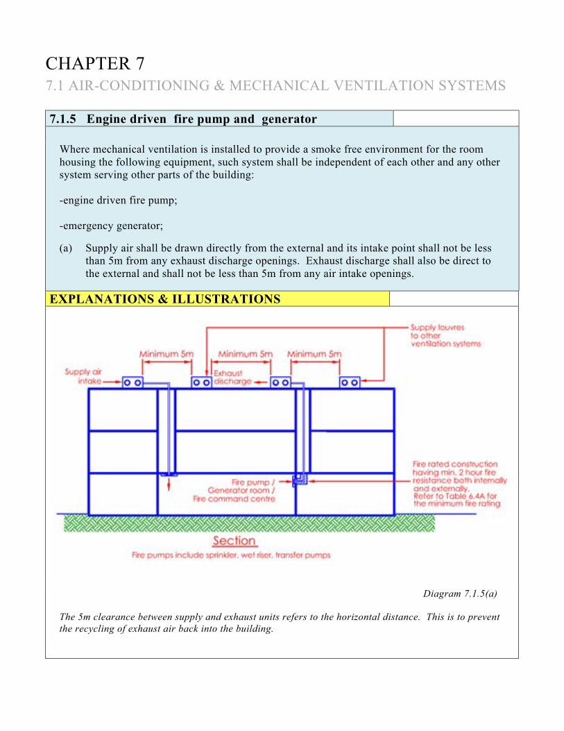
CHAPTER 7 7.1 AIR-CONDITIONING & MECHANICAL VENTILATION SYSTEMS 7.1.5 Engine driven fire pump and generator
Where mechanical ventilation is installed to provide a smoke free environment for the room housing the following equipment, such system shall be independent of each other and any other system serving other parts of the building: -engine driven fire pump; -emergency generator; (a) Supply air shall be drawn directly from the external and its intake point shall not be less
than 5m from any exhaust discharge openings. Exhaust discharge shall also be direct to the external and shall not be less than 5m from any air intake openings.
EXPLANATIONS & ILLUSTRATIONS
Diagram 7.1.5(a)
The 5m clearance between supply and exhaust units refers to the horizontal distance. This is to prevent the recycling of exhaust air back into the building.

(b) Where the corresponding ducts run outside the room they shall either be enclosed in a
structure or be constructed to give at least the same fire rating as the room which they serve or that of the room through which they traverse, whichever is higher. The rating shall apply to fire exposure from both internal and external of the duct or structure. Where the duct risers are required to be enclosed in a protected shaft constructed of masonry or drywall complying with Cl.3.8.9(a), they shall be compartmented from the rest of the shaft space containing other ducts or services installations.
EXPLANATIONS & ILLUSTRATIONS 7.1.5
Diagram 7.1.5(b)
The above diagram shows that the ducts that run outside the protected shaft are enclosed in a structure or be constructed to give the necessary fire resistance rating. However, for the riser ducts which pass through one or more floors they are required to be enclosed in masonry shaft or drywall as required under Cl.3.8.9(a). This is to ensure that the riser ducts are properly protected within a shaft. The enclosure would ensure the integrity and stability of the riser ducts which pass floor to floor. The provision of fire damper in the supply or exhaust duct is not allowed as the supply or exhaust system is required to function during emergency.

(c) No fire damper shall be fitted in either supply or exhaust duct required under this clause
EXPLANATIONS & ILLUSTRATIONS 7.1.5
Diagram 7.1.5(c)-1
The concern is the stability of the riser ducts, if they pass through one or more floors
Diagram 7.1.5(c)-2
As the mechanical ventilation system to generator room and fire pump room is independent of each other, the riser duct for each system shall be separately enclosed in a masonry or drywall shaft and compartmented from the rest of the shaft space containing other ducts or service installations. Clause 3.8.9(a) should also be referred to.

(d) Duct serving areas other than rooms housing equipment stated in this clause shall not pass
through such rooms.
EXPLANATIONS & ILLUSTRATIONS 7.1.5
Diagram 7.1.5(d)
Ducts serving other areas shall not pass through the fire pump room, generator room and fire command centre. The above diagram shows that the ventilation duct is diverted from traversing the equipment room.

CHAPTER 7 7.1 AIR-CONDITIONING & MECHANICAL VENTILATION SYSTEMS 7.1.6 Fire command centre
The Fire Command Centre can either be AC, NV, or MV. The AC or MV shall be independent of each other and any other system serving other parts of the building. Where mechanical ventilation is required, it shall also comply with the following requirements: (a) Supply air shall be drawn directly from the external and its intake point shall not be less
than 5m from any exhaust discharge openings. Exhaust discharge shall also be direct to the external and shall not be less than 5m from any air intake openings.
(b) Where the corresponding ducts run outside the fire command centre, they shall either be
enclosed in a structure or be constructed to give at least the same fire rating as the room which they serve or that of the room through which they traverse, whichever is higher. Where the duct risers are required to be enclosed in a protected shaft constructed of masonry or drywall complying with Cl.3.8.9(a), they shall be compartmented from the rest of the shaft space containing other ducts or services installations.
(c) No fire damper shall be fitted in either supply or exhaust duct required under this Clause. (d) Duct serving areas other than the fire command centre shall not pass through the room.
EXPLANATIONS & ILLUSTRATIONS 7.1.6
No illustration. For illustration of the above see Cl.7.1.5(a) to (d)

CHAPTER 7 7.1 AIR-CONDITIONING & MECHANICAL VENTILATION SYSTEMS 7.1.7 Kitchen
(a) Mechanical exhaust system for the cooking area of a kitchen in a hotel, restaurant, coffee
house or the like shall be independent of those serving other parts of the building. It shall also comply with the following requirements: The hood and ducts for the exhaust shall have a clearance of 500mm from unprotected combustible materials;
(i) The exhaust shall be discharged directly to the external and shall not be less than 5m
from any air intake openings; (ii) The exhaust duct where it runs outside the kitchen shall either be enclosed in a
structure or be constructed to give at least the same fire rating as the kitchen or that of the room through which it traverses, whichever is higher. The rating shall apply to fire exposure from both internal and external of the duct or structure. Where the duct riser is required to be enclosed in a protected shaft constructed of masonry or drywall complying with Cl.3.8.9(a), it shall be compartmented from the rest of the shaft space containing other ducts or services installations; and
(iii) No fire damper shall be fitted in kitchen exhaust ducts.
EXPLANATIONS & ILLUSTRATIONS
Diagram 7.1.7(a)(i)
The hood and duct should be separated from other combustible materials by a minimum horizontal clearance of 500mm to prevent ignition through heat radiation. Class F portable fire extinguishers shall be provided according to SS 578.

EXPLANATIONS & ILLUSTRATIONS 7.1.7(a)
Diagram 7.1.7(a)-1
Diagram 7.1.7(a)-2
Horizontal run of the exhaust duct outside the kitchen shall be fire rated with minimum 1 hour fire resistance rating. The 1 hour fire resistance shall be applicable to the inside and outside of the duct.

EXPLANATIONS & ILLUSTRATIONS 7.1.7(a)
Diagram 7.1.7(a)-3
The protecting structure for protected shaft containing kitchen exhaust duct that pass through one or more floors shall be of masonry construction or drywall. To eliminate the risk of fire spreading from one compartment to another through burning grease within the duct system, a separate exhaust system is required for each hood located in separate compartments. Fire dampers are not permitted within the duct system. The effectiveness of fire dampers is questionable as grease on the downstream side would likely ignite before the damper closed. The potential for false operation is also greater than normal and closure other than in a fire situation could have serious consequences. Further it is expected that the majority of kitchen hoods will have their own suppression thereby reducing the risk of fire spreading into the duct. Continuation of the exhaust system during a fire involving the cooking equipment or in the compartment is not considered to aggravate the situation.

(b) Sharing of kitchen exhaust system for food and beverage outlets is allowed provided the
following conditions are complied with: (i) For a food court
(1) the food court shall be under a single ownership/operator;
(2) there must be provision for maintenance and cleaning of the exhaust system;
(3) the food court owner/operator shall ensure that the kitchen exhaust system is
degreased and cleaned regularly; and
(4) all kitchen exhaust ducts running outside the food court shall have fire resistant rating of at least 1 hour or shall not be less than that for the elements of structure, whichever is the higher.
EXPLANATIONS & ILLUSTRATIONS 7.1.7
NRD- Non rated duct Diagram 7.1.7(b)(i) To share a kitchen exhaust system within a food court, it needs to be under a single ownership/operator. In addition, it is also required to make provision for maintenance and cleaning of the exhaust system, i.e. degreased & cleaned regularly. All kitchen exhaust ducts running outside the food court shall have minimum 1 hour fire-resistance rating or not less than that for the elements of structure, whichever is higher.

(ii) For restaurants
(1) the restaurants that are sharing the same kitchen exhaust system shall be located
next to each other and be on the same storey;
(2) the aggregate floor area of the restaurants shall not exceed 1,000m2;
(3) common duct shall be provided with common exhaust fan;
(4) there must be provision for maintenance and cleaning of the common exhaust system;
(5) the common kitchen exhaust system shall be degreased and cleaned regularly;
(6) the building shall be protected by an automatic fire sprinkler system;
(7) the exhaust hood shall be fitted with a wet chemical fire extinguishing system;
and
(8) the fire rating of the common kitchen exhaust duct running outside the restaurants shall have fire resistance rating of at least 1 hour or shall not be less than that for the elements of structure, whichever is the higher.
EXPLANATIONS & ILLUSTRATIONS 7.1.7(b)
NRD – non rated duct Diagram 7.1.7(b)(ii)
To be precise, each restaurant shall be provided with its own kitchen exhaust duct. Where the restaurants are located next to each other and on the same floor, the sharing of kitchen exhaust duct is permitted
EXPLANATIONS & ILLUSTRATIONS 7.1.7(b)(ii) Where the restaurants are located far from each other, then the relaxation of common kitchen exhaust duct shall not be applicable. In other words, each restaurant unit shall have its own kitchen exhaust duct. Please note that to qualify for relaxation of sharing kitchen duct, the conditions (1) to (8) shall be provided for.

(iii) For other smaller F&B outlets such as snack bars, food kiosks etc.
(1) the F&B outlets that are sharing kitchen exhaust system shall be:
∗ within close proximity from each other; ∗ within a zone of 1,000m2; ∗ with hood-to-hood distance of not more than 10m; and ∗ located on the same storey.
(2) the kitchen exhaust duct running outside the F&B outlets shall have fire resistance rating of at least 1 hour or shall not be less than that for the elements of structure, whichever is the higher; and
(3) all other conditions stipulated in (ii)(3) to (7) above shall be complied with.
(Note: Kitchen exhaust duct includes both horizontal and vertical ducts) EXPLANATIONS & ILLUSTRATIONS 7.1.7(b)
NRD – non rated duct Diagram 7.1.7(b)(iii) This relaxation will address smaller food outlets which may came in the form of kiosks or push-cart counters. To qualify for sharing of kitchen exhaust duct, each kiosk shall be in close proximity within a zone of 1000m². The distance between hoods of adjacent kiosks shall not exceed 10m and be located at the same storey.

CHAPTER 7 7.1 AIR-CONDITIONING & MECHANICAL VENTILATION SYSTEMS 7.1.8 Rooms involving use of flammable and explosive
substances
(a) Mechanical ventilation system where required for rooms which involve the use of
flammable and explosive substances shall be independent from those serving other parts of the building. It shall comply with the following requirements:
(i) Ventilation system shall consist of exhaust and supply part with a rate of 20
air-change per hour or any other rates acceptable to the Relevant Authority. The exhaust shall be direct to the external and shall not be less than 5m from any air intake openings;
(ii) Where such ducts run outside the room they shall either be enclosed in a structure
or be constructed to give at least the same fire rating as the room which they serve or that of the room through which they traverse, whichever is higher. The rating shall apply to fire exposure from both internal and external of the duct or structure.Where the duct risers are required to be enclosed in a protected shaft constructed of masonry or drywall complying with Cl.3.8.9(a), they shall be compartmented from the rest of the shaft space containing other ducts or services installations;
(iii) No fire damper shall be fitted in either supply or exhaust duct required under this
Clause; and (iv) Ducts serving other areas shall not pass through rooms involving use of flammable
and explosive substances.

EXPLANATIONS & ILLUSTRATIONS 7.1.8
Diagram 7.1.8-1
The exhaust system (without fire damper) is required to operate efficiently to remove any gaseous or flammable vapour from the room. (a) Where the flammable vapour being removed is heavier than air,
(i) At least one air outlet shall be located at a point near a wall, and no higher than 300mm from the floor, and
(ii) At least one air inlet shall be located near the opposite wall, no lower than 300mm from
the ceiling. (b) Where the flammable vapour being removed is lighter than air,
(i) At least one air inlet shall be located at a point near a wall, and no higher than 300mm from the floor, and
(ii) At least one air outlet shall be located near the opposite wall, no lower than 300mm
from the ceiling.

EXPLANATIONS & ILLUSTRATIONS 7.1.8
Diagram 7.1.8-2
The flammable vapour which is heavier than the air will be discharged via the exhaust system (without damper) as shown above. Do refer to relevant SS for full compliance.
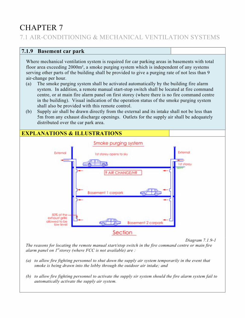
CHAPTER 7 7.1 AIR-CONDITIONING & MECHANICAL VENTILATION SYSTEMS 7.1.9 Basement car park
Where mechanical ventilation system is required for car parking areas in basements with total floor area exceeding 2000m², a smoke purging system which is independent of any systems serving other parts of the building shall be provided to give a purging rate of not less than 9 air-change per hour. (a) The smoke purging system shall be activated automatically by the building fire alarm
system. In addition, a remote manual start-stop switch shall be located at fire command centre, or at main fire alarm panel on first storey (where there is no fire command centre in the building). Visual indication of the operation status of the smoke purging system shall also be provided with this remote control.
(b) Supply air shall be drawn directly from the external and its intake shall not be less than 5m from any exhaust discharge openings. Outlets for the supply air shall be adequately distributed over the car park area.
EXPLANATIONS & ILLUSTRATIONS
Diagram 7.1.9-1 The reasons for locating the remote manual start/stop switch in the fire command centre or main fire alarm panel on 1ststorey (where FCC is not available) are : (a) to allow fire fighting personnel to shut down the supply air system temporarily in the event that
smoke is being drawn into the lobby through the outdoor air intake; and
(b) to allow fire fighting personnel to activate the supply sir system should the fire alarm system fail to automatically activate the supply air system.

(c) Where there is natural ventilation for such basement car park based upon openings equal
to not less than 2.5% of the floor area of such storey, such natural ventilation may be considered as a satisfactory substitute for the supply part of the smoke purging system. The openings shall be evenly distributed over the car park areas.
(d) Exhaust air shall be discharged directly to the external and shall not be less than 5m from
any air intake openings. (e) Exhaust ducts shall be fabricated from heavy gauge steel (1.2mm thick) for the basement
car park smoke purging system. (f) Exhaust fans of the basement car park smoke purging system shall be capable of
operating effectively at 2500C for 2 hours. EXPLANATIONS & ILLUSTRATIONS 7.1.9
Diagram 7.1.9-2
Exhaust fans shall be rated at minimum 250°C. Supply air part of the smoke purging system is provided via opening to the external air. The openings provided for supply air shall not be less than 2.5% of the floor area of each basement storey. Ramp openings, voids over car parking areas are considered acceptable openings for fresh air supply. Where a smoke purging system consists of a supply and exhaust , both of which shall be designed such that each can operate in two sections.

EXPLANATIONS & ILLUSTRATIONS 7.1.9 The capacity of each section shall be sufficient to provide half the air changes required. Each section of the smoke purging system shall so constructed that in the event of failure of one section (exhaust part or supply part), the other section shall continue to operate. This can prevent failure of the system caused by failure of one single fan. The exhaust and supply parts shall be electrically interlocked so that failure of any section of the exhaust part shall automatically shut down the corresponding section of the supply part, which can prevent total failure of the smoke purging system caused by the failure of one single fan. In the event that any exhaust fan fails to run or is shut down for maintenance, the corresponding supply fan should not run so as to prevent fresh air from being pumped into the basement. The interlocking arrangement will not apply if smoke purging system consists of only the exhaust part. However, the exhaust system shall also be designed into two section as per the above.

CHAPTER 7 7.2 PRESSURISATION FOR EXIT STAIRCASES
7.2.1 General
(a) In any building of which the habitable height exceeds 24m, any internal exit staircases
without adequate provision for natural ventilation shall be pressurised to comply with the requirements in this Code. Where the upper part of the staircase is naturally ventilated, its lower part can be provided with mechanical ventilation or pressurisation, whichever is appropriate in accordance with Cl.2.3.3(h).
(b) In a building comprising more than 4 basement storeys, exit staircase connected to fire-fighting lobby in basement storeys shall be pressurised to comply with the requirements in this Code.
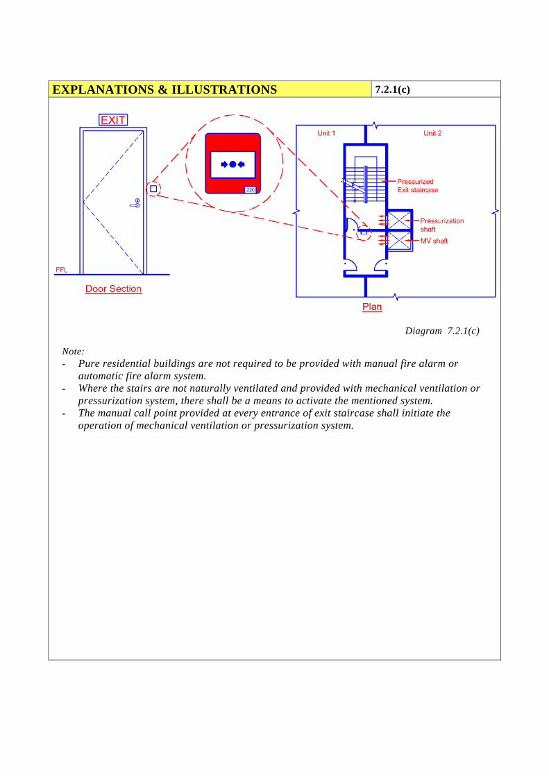
(c) Where Purpose Group II staircase storey shelter is provided with mechanical ventilation
system or pressurisation system for its exit staircase, a manual fire alarm system complying with SS CP 10 shall be installed. The manual call point shall be located at the entrance of each exit staircase at every storey, including the non-residential floors. Activation of any manual call point shall initiate the operation of mechanical ventilation system or pressurisation system.

EXPLANATIONS & ILLUSTRATIONS 7.2.1(a)
Diagram 7.2.1(a)-1
The above clause specifies that all internal staircases without provision for natural ventilation of building having more than 24m in habitable height, shall be provided with pressurisation notwithstanding that smoke stop lobby is provided. Smoke stop lobby,if mechanically ventilated, is to be provided with supply air of at least 10 air change per hour during fire mode. There shall be no exhaust duct extracting air out from the smoke stop lobby. The need of a dedicated pressurisation system (two fans are recommended, capacity of each fan shall be provided for 50% equipment) for each exit staircase is to prevent failure of one system affecting all exits. Air supply to the exit staircase must be obtained from outside the building to minimise the risk of contamination from smoke resulting from a fire in the building. Ductwork associated with the discharge of air throughout the staircase may be located within the staircase itself, otherwise it must be protected in a masonry or fire rated shaft. To achieve the required air flow velocity on any storey, air supplied by the system should be evenly distributed throughout the height of the staircase by ductwork with outlets located not more than two storeys apart. Relief air grilles (pressure relief dampers) could be used for pressure control thereby minimising periods of excessive force to open doors of the staircases. Variable speed fans with pressure relief damper can be accepted as alternative arrangement.

EXPLANATIONS & ILLUSTRATIONS 7.2.1(a)
Diagram 7.2.1(a)-2
Internal exit staircase without adequate ventilation at lower part can be mechanically ventilated provided the lower part shall not exceed 24m in habitable height. Where the lower part exceed 24m, the internal exit staircase shall be pressurized.

EXPLANATIONS & ILLUSTRATIONS 7.2.1(a)
Building exceeding 24m in habitable height
Diagram 7.2.1(a)-3
Exit staircase (A) is pressurised as it is located within the floor space where natural ventilation cannot be provided. Exit staircase, which is designed without provision for natural ventilation, is pressurised. Smoke stop lobby is also required to be provided to staircase A.

EXPLANATIONS & ILLUSTRATIONS 7.2.1(a)
Diagram 7.2.1(a)-4
Exit staircase (B) is pressurised as it is located within the floor space where natural ventilation can not be provided. Exit staircase (C), which is designed without provision for natural ventilation, is pressurised. Notwithstanding clause 2.2.13(c), smoke stop lobby is required to be provided to all internal staircases, without provision for natural ventilation, serving building exceeding the habitable height of 24m.

EXPLANATIONS & ILLUSTRATIONS 7.2.1(a)
Diagram 7.2.1(a)-5
Staircase A and transfer staircase A1 are considered as one single staircase sharing a common protected shaft. As staircase A is an internal staircase without openings for natural ventilation, exceeding a habitable height of 24m, it is required to be provided with M/V and pressurisation. Since, staircase A1 is acting as a transfer staircase, it shall likewise be M/V and pressurised notwithstanding the fact it can be naturally ventilated through external openings. The transfer exit passageway which connects staircases A and A1 should also be M/V and pressurised. It is not acceptable to have partial pressurisation to staircase A by introducing a door across the transfer passageway, such that staircase A1 is separated for the provision of natural ventilation. The reason is that by providing a door across the transfer passageway, it would impede the movement of occupants moving towards staircase A1. In this way, the evacuation process within the whole shaft of staircase A would be slowed down.
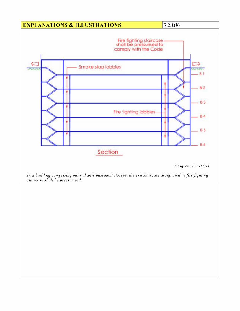
EXPLANATIONS & ILLUSTRATIONS 7.2.1(b)
Diagram 7.2.1(b)-1
In a building comprising more than 4 basement storeys, the exit staircase designated as fire fighting staircase shall be pressurised.

EXPLANATIONS & ILLUSTRATIONS 7.2.1(b)
Diagram 7.2.1(b)-2
Owing to difference in ground levels, staircase B is serving more than 4 basements and is therefore designated as a fire fighting staircase complemented with a fire fighting lobby at each storey.
EXPLANATIONS & ILLUSTRATIONS 7.2.1(c)
Diagram 7.2.1(c)
Note: - Pure residential buildings are not required to be provided with manual fire alarm or
automatic fire alarm system. - Where the stairs are not naturally ventilated and provided with mechanical ventilation or
pressurization system, there shall be a means to activate the mentioned system. - The manual call point provided at every entrance of exit staircase shall initiate the
operation of mechanical ventilation or pressurization system.

CHAPTER 7 7.2 PRESSURISATION FOR EXIT STAIRCASES
7.2.2 Pressurisation Level
(a) When in operation, the pressurisation system shall maintain a pressure differential of not
less than 50 Pa between the pressurised exit staircase and the occupied area when all doors are closed.
(b) Where a smoke-stop lobby is also pressurised, the pressure at the exit staircase shall
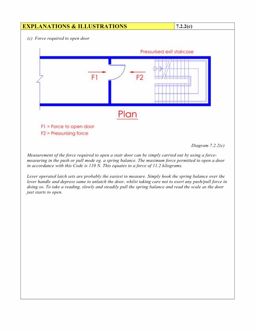
always be higher. (c) The force required to open any door against the combined resistance of the pressurising
air and the automatic door-closing mechanism shall not exceed 110 N at the door handle.
EXPLANATIONS & ILLUSTRATIONS
(a) Maintaining pressure differential
Diagram 7.2.2(a)

EXPLANATIONS & ILLUSTRATIONS 7.2.2(b)
(b) Pressure gradient
Diagram 7.2.2(b)
Where the smoke stop lobby is pressurised, the pressure gradient shall be such that the pressure at the exit staircase is always higher.
EXPLANATIONS & ILLUSTRATIONS 7.2.2(c)
(c) Force required to open door
Diagram 7.2.2(c)
Measurement of the force required to open a stair door can be simply carried out by using a force-measuring in the push or pull mode eg. a spring balance. The maximum force permitted to open a door in accordance with this Code is 110 N. This equates to a force of 11.2 kilograms. Lever operated latch sets are probably the easiest to measure. Simply hook the spring balance over the lever handle and depress same to unlatch the door, whilst taking care not to exert any push/pull force in doing so. To take a reading, slowly and steadily pull the spring balance and read the scale as the door just starts to open.

CHAPTER 7 7.2 PRESSURISATION FOR EXIT STAIRCASES
7.2.3 Egress velocity
When in operation, the pressurisation system shall maintain an airflow of sufficient velocity through open doors to prevent smoke from entering into the pressurised area. The flow velocity shall be attained when a combination of two doors from any two successive storeys and the main discharge door are fully open. Magnitude of the velocity averaged over the full area of each door opening shall not be less than 1.0 m/s.
EXPLANATIONS & ILLUSTRATIONS
Air flow velocity through open door to prevent
smoke from entering into the pressurised staircase
Diagram 7.2.3-1

EXPLANATIONS & ILLUSTRATIONS 7.2.3
Diagram 7.2.3-2
The air flow velocity measurement through an open door of a pressurised staircase is taken from the entrance of any of two successive doors held open together with its exiting door at the 1st storey. The resulting value of its airflow velocity through the open door shall not be less than 1m/s. Tests conducted by the Commonwealth Scientific and Industrial Research Organization (CSIRO) have demonstrated that air flows in excess of 0.8m/s through a door will minimise the spread of smoke against the direction of flow. A minimum air flow rate of 1m/s has therefore been adopted. This air flow must be maintained across the doorway providing egress from the fire-affected storey into the staircase during a fire. Initially, building occupants from both the fire floor and the floor above the fire floor will evacuate the building and, depending on the fire situation, this may be simultaneous operation. The requirement for two floor doors and the 1st storey door (opening into the exterior) to be open the same time has two applications: (i) When the fire fighters arrive and use the staircase for fire fighting operations, hose connection
to the landing valves located on a floor would be carried out. Initially hose will be run from the floor below up the staircase and onto the fire floor hence a minimum opening of two doors is involved.
(ii) All required exit staircases must be usable at the same time as either fire fighters or evacuating occupants will be using any of them to exit at the 1st storey door to the street or external safe open area. Thus the final exit door would remain in the open position at all times.
CHAPTER 7 7.2 PRESSURISATION FOR EXIT STAIRCASES
7.2.4 Leakages
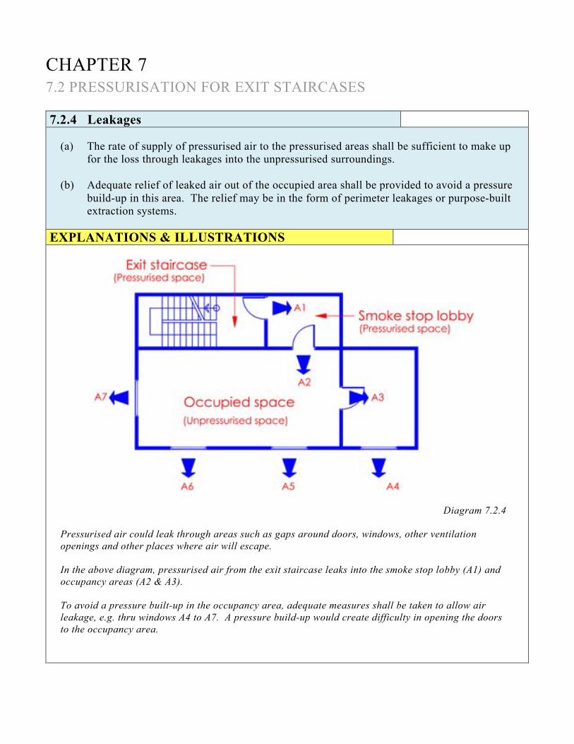
(a) The rate of supply of pressurised air to the pressurised areas shall be sufficient to make up for the loss through leakages into the unpressurised surroundings.
(b) Adequate relief of leaked air out of the occupied area shall be provided to avoid a pressure build-up in this area. The relief may be in the form of perimeter leakages or purpose-built extraction systems.
EXPLANATIONS & ILLUSTRATIONS
Diagram 7.2.4
Pressurised air could leak through areas such as gaps around doors, windows, other ventilation openings and other places where air will escape. In the above diagram, pressurised air from the exit staircase leaks into the smoke stop lobby (A1) and occupancy areas (A2 & A3). To avoid a pressure built-up in the occupancy area, adequate measures shall be taken to allow air leakage, e.g. thru windows A4 to A7. A pressure build-up would create difficulty in opening the doors to the occupancy area.

EXPLANATIONS & ILLUSTRATIONS 7.2.4
The following are possible ways in which the escape of pressurizing air can be achieved: (a) by window leakage;
(b) by specially provided vents at the building periphery;
(c) by the provision of vertical shaft.
(d) by mechanically operated extraction.

CHAPTER 7 7.2 PRESSURISATION FOR EXIT STAIRCASES
7.2.5 Distribution of pressurising air
(a) The number and distribution of injection points for supply of pressurising air to the exit staircase should ensure an even pressure profile complying with Cl.7.2.2.
(b) The arrangement of the injection points and the control of the pressurisation system shall
be such that when opening of doors or other factors cause significant variations in pressure difference, condition in Cl.7.2.2 should be restored as soon as practicable.
EXPLANATIONS & ILLUSTRATIONS
Diagram 7.2.5
The above installation is not acceptable as over pressurisation would occur at the upper portion of the staircase. Supply air to the staircase should be well distributed by a vertical supply duct, preferably serving all the levels of the staircase. An example of an arrangement showing good distribution of supply air can be seen in diagram 7.2.6.

CHAPTER 7 7.2 PRESSURISATION FOR EXIT STAIRCASES
7.2.6 Equipment
(a) All the equipment and the relevant controls associated with the pressurisation system shall be so designed and installed to ensure satisfactory operation in the event of and during a fire.
(b) Supply air for pressurisation system shall be drawn directly from the external and its intake shall not be less than 5m from any exhaust discharge openings.
(c) The pressurisation system shall be automatically activated by the building fire alarm system. In addition, a remote manual start-stop switch shall be made available to firemen at the fire command centre, or at the fire indicating board where there is no fire command centre. Visual indication of the operation status of the pressurisation system shall be provided.
EXPLANATIONS & ILLUSTRATIONS
Diagram 7.2.6
The “start-stop” switch is required to be provided in the Fire Command Centre, or FIB where there is no FCC. The rationale is to provide the fire fighters greater ease and better control in operating the supply air fan to the staircase. This arrangement facilitate the supply air fan to be shut from the designated remote “start-stop" location. The supply air fan can then be restarted anytime when required.

CHAPTER 7 7.3 PRESSURISATION OF INTERNAL CORRIDORS IN HOTELS 7.3.1 Pressurisation of internal corridors in hotels
Where internal corridors in hotels are required to be pressurised in compliance with Cl.2.7.1(c), the pressure within such corridors shall be higher than that in the guest rooms and the pressure within the internal exit staircases higher than that of the corridors.
EXPLANATIONS & ILLUSTRATIONS
Diagram 7.3.1-1
Provision of pressurisation to the internal corridor would help to check the migration of smoke from any of the guest rooms. The pressure gradient shall be such that : P1>P2>P3

EXPLANATIONS & ILLUSTRATIONS 7.3.1
Acceptable – Diagrams 7.3.1-2 to 7.3.1-6
More than 4 storey – (Internal staircase)
Diagram 7.3.1-2
The above diagram illustrates a mechanical ventilated smoke stop lobby and an internal staircase to be pressurised accordingly. The pressure gradient shall be such that the pressure at the exit staircase shall always be higher.
EXPLANATIONS & ILLUSTRATIONS 7.3.1
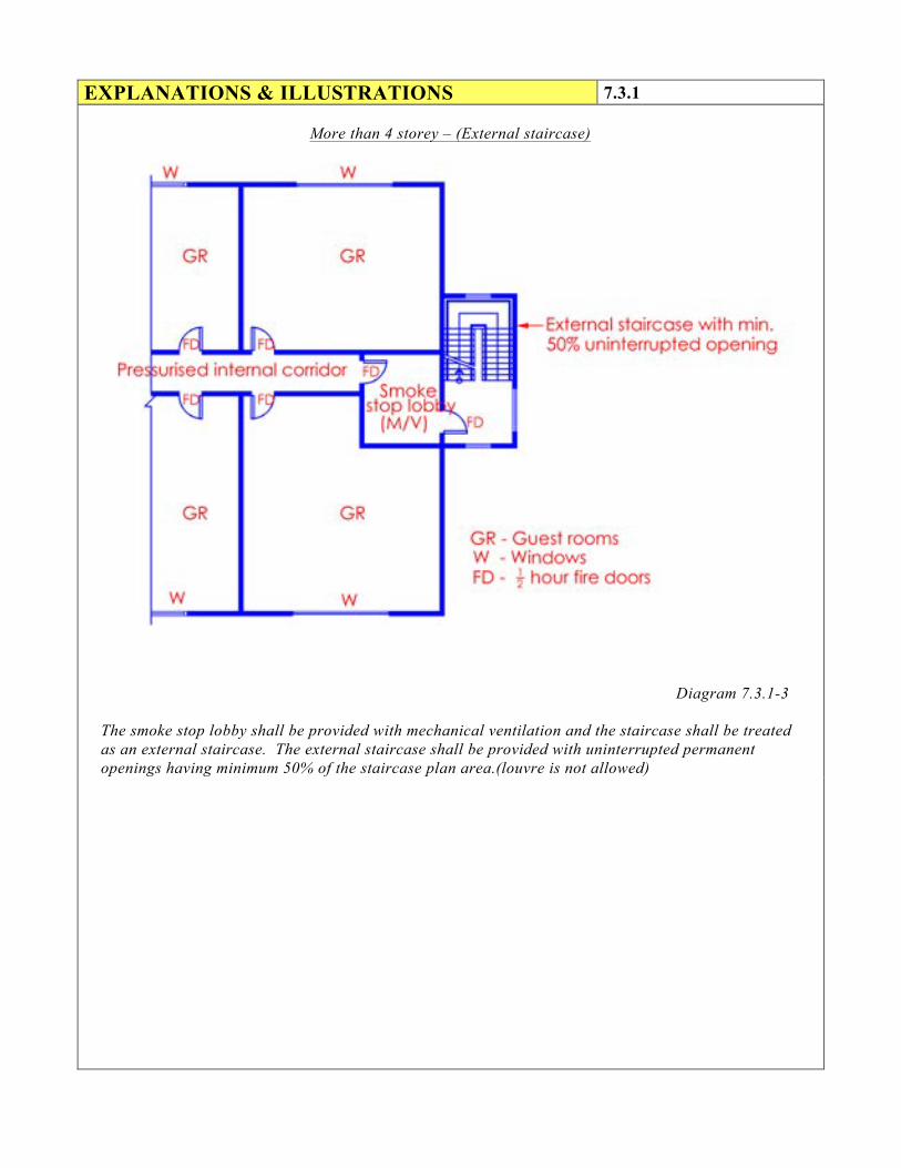
More than 4 storey – (External staircase)
Diagram 7.3.1-3
The smoke stop lobby shall be provided with mechanical ventilation and the staircase shall be treated as an external staircase. The external staircase shall be provided with uninterrupted permanent openings having minimum 50% of the staircase plan area.(louvre is not allowed)

EXPLANATIONS & ILLUSTRATIONS 7.3.1
More than 4 storey – (External staircase)
Diagram 7.3.1-4
The above diagram illustrates a naturally ventilated smoke stop lobby and external staircase. The smoke stop lobby shall be provided with minimum 15% external openings. The external staircase shall be provided with uninterrupted permanent openings having minimum 50% of the staircase plan area.(louvre is not allowed)

EXPLANATIONS & ILLUSTRATIONS 7.3.1
Not more than 4 storey – (External staircase)
Diagram 7.3.1-5
The internal corridor leading to the exit should be via a minimum 1 hour fire resistance door. The external staircase shall be provided with uninterrupted permanent openings having 50% of the staircase plan area. .(louvre is not allowed)

EXPLANATIONS & ILLUSTRATIONS 7.3.1
Not more than 4 storey – (Internal staircase)
Diagram 7.3.1-6
In the above diagram, the provision of smoke stop lobby is not required by virtue of its height under cl. 2.2.13. The staircase is an internal staircase, as such it shall be pressurised to have a higher pressure differential than the internal corridor.

EXPLANATIONS & ILLUSTRATIONS 7.3.1
Not more than 4 storey
Diagram 7.3.1-7
The above diagram shows a simple pressurisation system suitable for small hotels. It consists of fans, which are connected to smoke sensitive device so that they operate in fire emergency. The corridor shall be provided with pressurisation to maintain a positive pressure. The power and capacity of the fan is calculated after evaluation of air leakage factors, so that an adequate pressure differential can be developed between the corridor and the guestrooms. For effective pressurisation, there must be sufficient leakage through the external envelope of the building so that the pressure in the fire room will not reach the same pressure level with the pressure in the protected corridor.

CHAPTER 7 7.4 BASEMENT SMOKE CONTROL SYSTEM 7.4.1 Scope
(a) Where the total aggregate floor area of all basement storeys does not exceed 2000m², smoke vents in accordance with Cl.7.4.2 shall be provided.
EXPLANATIONS & ILLUSTRATIONS
Diagram7.4.1(a)-1

EXPLANATIONS & ILLUSTRATIONS 7.4.1(a)
Diagram 7.4.1(a)-2
Total aggregate floor area of basement storeys = Area of car park + staircases + services area (TAS, Transformer room etc) + plant/equipment room of basement 1 + Area of whole basement 2. If total aggregate area< 2000m² (see clause 7.4.2). If total aggregate area>2000m² (engineered smoke
control system or smoke purging is required), See also clauses 7.1.9 and 7.4.1(b)(ii) & (iii).

(b) Exception
Where the total aggregate floor area of all basement storeys exceeds 2000m², engineered smoke control system that complies with the requirements stipulated in Cl.7.4.3 shall be provided for all parts of basement with the following exceptions: (i) Where the basement or a portion of the basement is used as carpark, Cl.7.1.9 can be
adopted to the carpark provided it is compartmented from rest of the basement;
(ii) Plant/equipment room with floor area not exceeding 250m² and compartmented from rest of the basement, and provided with two doors for better reach in fire fighting operation.
(iii) Plant/equipment room with floor area exceeding 250m² but not exceeding 2000m², smoke
vents in accordance with Cl.7.4.2 or smoke purging system of at least 9 air-change per hour shall be provided.
(iv) Service areas such as storeroom and workshops (restricted to staff only) which are
compartmented, smoke venting provision in accordance with Cl.7.4.2 or smoke purging system of at least 9 air-change per hour may be accepted for those areas in lieu of the engineered smoke control system. Automatic fire alarm/extinguishing system in accordance with Table 6.4A shall be provided where required.
EXPLANATIONS & ILLUSTRATIONS 7.4.1
Diagram 7.4.1(b)(i)
If the total floor area of basements 1 & 2 (other usage + car park) >2000m², engineered smoke control is required to be provided in the basement storeys; except the car parking areas in basements 1 & 2 which need to be provided with smoke purging system under clause 7.1.9.

EXPLANATIONS & ILLUSTRATIONS 7.4.1(b)
Diagram 7.4.1(b)(ii)
Where the plant/equipment room is not greater than 250m², fire fighters can fight a fire in that room from its doorway.

EXPLANATIONS & ILLUSTRATIONS 7.4.1(b)
Diagram 7.4.1(b)(iii)
Where floor area of the plant/equipment room is in excess of 250m², but not exceeding 2000m², provision of smoke vents in accordance to Cl.7.4.2 or smoke purging system in accordance with Cl.7.1.9 would be acceptable. Subclause (iii) is meant to grant relaxation over the general requirement as service rooms are usually of low occupancy load. Common areas outside the plant rooms/service rooms shall be provided with engineered smoke control system.

EXPLANATIONS & ILLUSTRATIONS 7.4.1(b)
Diagram 7.4.1(b)(iii)
The above clause is mainly applicable to hotel building. Service areas such as stores and workshops are restricted to staff only shall be compartmented. The total area of these compartments shall not exceed 2000m²(per storey basis). Each compartment shall be provided with smoke venting or smoke purging system.

EXPLANATIONS & ILLUSTRATIONS 7.4.1(b)
Diagram 7.4.1(b)(iv)
- Service areas in basement storey used as office and laundry area are areas that are normally
occupied. - Hence smoke dilution of at least 9 air-charges may not suffice. - Adequate level of visibility and smoke dispersal shall be maintained for these areas to facilitate
escape. - Engineered smoke control system shall be provided.

CHAPTER 7 7.4 BASEMENT SMOKE CONTROL SYSTEM 7.4.2 Smoke vents
Smoke vents shall be adequately distributed along perimeter of basement and their outlets shall be easily accessible during fire fighting and rescue operations. Installation shall comply with the following requirements:
(a) The number and their sizes shall be such that the aggregate effective vent openings shall
not be less than 2.5% of the basement floor area served. (b) The vent outlets if covered under normal conditions shall be openable in case of fire. (c) The position of all vent outlets and the areas they serve shall be suitably indicated
adjacent to such outlets. (d) Where ducts are required to connect the vent to outlets, the ducts shall either be enclosed
in structure or be constructed to give at least 1 hour fire resistance. (e) Separate ducts and vent outlets shall be provided for each basement storey.
EXPLANATIONS & ILLUSTRATIONS
Diagram 7.4.2

EXPLANATIONS & ILLUSTRATIONS 7.4.2 • smoke ventilation shafts where extending through storeys above, shall be enclosed with imperforate
walls having minimum 1 hour fire resistance
• Separate smoke ventilation shafts and outlets shall be provided for each basement storey.
• Smoke venting outlets shall be so arranged that a through draught can be created.
• Outlets covered by stalled boards, or approved type pavement lights shall be readily openable/breakable.
• The positions of all smoke vent outlets and the basement level or areas they serve shall be suitably
indicated on the external face of the building adjacent to such outlets.

CHAPTER 7 7.4 BASEMENT SMOKE CONTROL SYSTEM
7.4.3 Engineered smoke control
Where engineered smoke control system is required, it shall be provided as specified in Cl.7.6. EXPLANATIONS & ILLUSTRATIONS
No illustration. (See clause 7.6)

CHAPTER 7 7.4 BASEMENT SMOKE CONTROL SYSTEM 7.4.4 Smoke purge system for non- car park occupancy
Smoke purging systems, where permitted under this Code in buildings for basement occupancies of plant/equipment room and service areas such as laundries, office, storeroom and workshops, shall conform to the following requirements: (a) The purge rate shall be at least 9 air changes per hour.
(b) The smoke purging system shall be activated automatically by the building fire alarm
system. In addition, a remote manual start-stop switch shall be located at fire command centre, or in the absence of a fire command centre in the building, at the main fire alarm panel on the first storey. Visual indication of the operational status of the smoke purging system shall also be provided with this remote control.
(c) Horizontal ducts shall be fabricated from heavy gauge steel (1.2mm thick).
(d) The exhaust fan shall be capable of operating effectively at 250oC for 2 hours and
supplied from a secondary source of supply.
(e) Replacement air shall be provided and if it is supplied by a separate mechanical system, such a system shall be connected to a secondary source of power.
EXPLANATIONS & ILLUSTRATIONS
No illustration.

CHAPTER 7 7.5 SMOKE CONTROL SYSTEM 7.5.1 Smoke control system
A smoke control system specified in Cl.7.6 shall be provided where: (i) The requirements for compartmentation specified in Cl.3.2.1 and 3.2.4(a) and (b) are
relaxed under the conditions in Cl.3.2.6 for `Atrium spaces' in a building; and
(ii) The total floor area of any compartment in a building or part of a building exceeds 5000m².

EXPLANATIONS & ILLUSTRATIONS 7.5.1
Diagram 7.5.1
Before the use of engineered smoke control system is allowed in any proposal, the Relevant Authority shall be satisfied that the compartment height of atrium is connecting more than 3 storeys below the habitable height of 24m;
The Qualified persons are required to consult SCDF(FSSD) to seek consent before making any plan submission. The consent that is given by SCDF (FSSD) to allow the use of engineered smoke control system in the proposal shall only relate to the relaxation on the compliance with the above requirements under Cl.3.2.1 and Cl.3.2.4(a) and (b) of the Fire Code. Where more than 3 storeys are interconnected and the size and volume is relaxed with provision of atrium smoke control system, only the first basement is allowed to form part of the upper storey. A smoke control system shall be provided to any compartment in a building or part of a building which has a total floor area greater than 5000 m². Smoke from any fire in such compartment would easily find its way into escape routes leading to exits or exit staircases. The activation of the smoke control system would ensure that the smoke layer would not be lower than 1.8m from floor level to allow occupants to find their ways to the exits or exit staircases.
CHAPTER 7 7.6 ENGINEERED SMOKE CONTROL SYSTEM
7.6.1 Acceptable design guidance
The engineered smoke control system shall be in the form of a smoke ventilation system by natural or mechanical extraction designed in accordance with: (a) BR 186 - Design principles for smoke ventilation in enclosed shopping centres; and
(b) BR 258 - Design approaches for smoke control in atrium buildings; or
(c) BR 368 - Design methodologies for smoke and heat exhaust ventilation (BR 368 is
published by Construction Research Communications Ltd by permission of Building Research Establishment Ltd); or
(d) Other acceptable standards.
(Note: BR 186 and 258 are reports published by the Fire Research Station, Building Research Establishment, Borehamwood, Herts WD62BL).
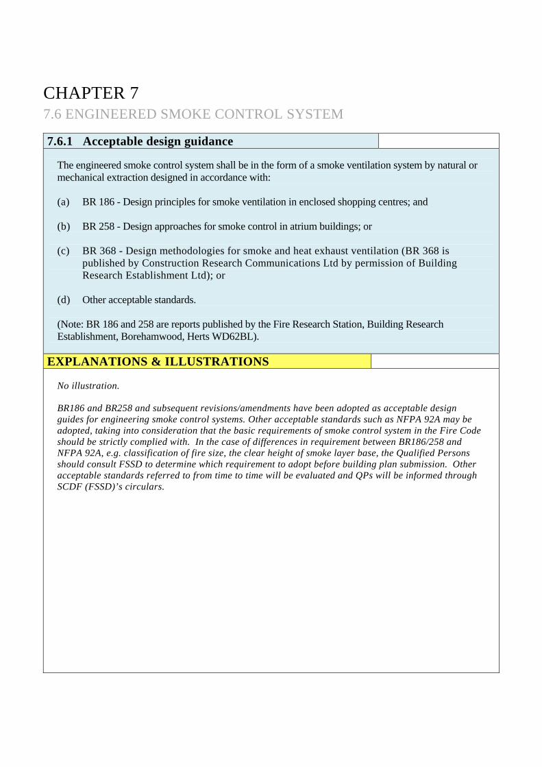
EXPLANATIONS & ILLUSTRATIONS
No illustration. BR186 and BR258 and subsequent revisions/amendments have been adopted as acceptable design guides for engineering smoke control systems. Other acceptable standards such as NFPA 92A may be adopted, taking into consideration that the basic requirements of smoke control system in the Fire Code should be strictly complied with. In the case of differences in requirement between BR186/258 and NFPA 92A, e.g. classification of fire size, the clear height of smoke layer base, the Qualified Persons should consult FSSD to determine which requirement to adopt before building plan submission. Other acceptable standards referred to from time to time will be evaluated and QPs will be informed through SCDF (FSSD)’s circulars.

CHAPTER 7 7.6 ENGINEERED SMOKE CONTROL SYSTEM 7.6.2 Sprinkler system
The building to be provided with an engineered smoke control system shall be sprinkler protected.
EXPLANATIONS & ILLUSTRATIONS
No illustration. The main reason that sprinkler system must be provided is to control the fire size. The sprinkler head spacing in respect of both hazard and classification determines the size of a fire, in area and perimeter. The activation of sprinkler heads would, besides controlling the fire size, help to reduce the build-up of heat and toxic gases, which can lead to flashover and smoke explosions. Based on research, if the fire is not sprinkler controlled, the fire size could be unlimited and therefore, fire size could not be established.

CHAPTER 7 7.6 ENGINEERED SMOKE CONTROL SYSTEM 7.6.3 Fire size
Capacity of the engineered smoke control system shall be calculated based on the incidence of a likely maximum fire size for a sprinkler controlled fire as recommended in the following table:
Occupancy (Sprinklered)
Fire Size Heat Output
(MW) Perimeter of Fire (m)
Shops 5 12
Offices 1 14
Hotel Guest Room 0.5 6
Hotel Public Areas 2.5 12 Assembly Occupancy with fixed seating
2.5 12
EXPLANATIONS & ILLUSTRATIONS
No illustration. The above examples of fire sizes under sprinkler control fire are recommended by Fire Research Station. The Smoke Ventilation Association (UK) recommended that one of the following steady state fire sizes could be used:
Example of building type Fire size Area Perimeter
Breweries 3m X 3m 9m² 12m
Bakeries 4.5m X 4.5m 20.25m² 18m
Paint manufacturing 9m X 9m 81m² 36m
Electrical warehouse 3m X 3m 9m² 12m
Pharmaceutical warehouse 4.5m X 4.5m 20.25m² 18m
Paper storage warehouse 6m X 6m 36m² 24m
Plastic storage warehouse 9m X 9m 81m² 36m

EXPLANATIONS & ILLUSTRATIONS 7.6.3
Criteria have been established which estimates heat output from certain tested materials. The document (CP 40/78 issued by the Fire Research Station), establishes data for fire incidents and experimental fires. Some examples of estimated burning rate of selected materials are as follows:
Building contents Estimated burning rate per unit area of fire (KW/m²)
1 Crated furniture 100
2 Vehicles, paint 260
3 Stacked sawn timber 390
4 Books, furniture 93
5 Stacked cardboard 320
6 Stacked chipboard 86
7 Cartons, electrical goods 310
8 Cardboard cartons 620
9 Cardboard reels 210
10 Packaged goods 540
11 Undefined goods 500 Further values can be found in FRS Note 13/93. The above values are to be used for typical storage arrangement and not high rack or palletted storage. Do refer to latest revision & consult SCDF (FSSD) to seek consent before making any plan submission.

CHAPTER 7 7.6 ENGINEERED SMOKE CONTROL SYSTEM
7.6.4 Capacity of an engineered smoke control system
The capacity of an engineered smoke control system shall be capable of handling the largest demand for smoke exhaust from the worst case scenario.
EXPLANATIONS & ILLUSTRATIONS
Diagram 7.6.4-1
EXPLANATIONS & ILLUSTRATIONS 7.6.4
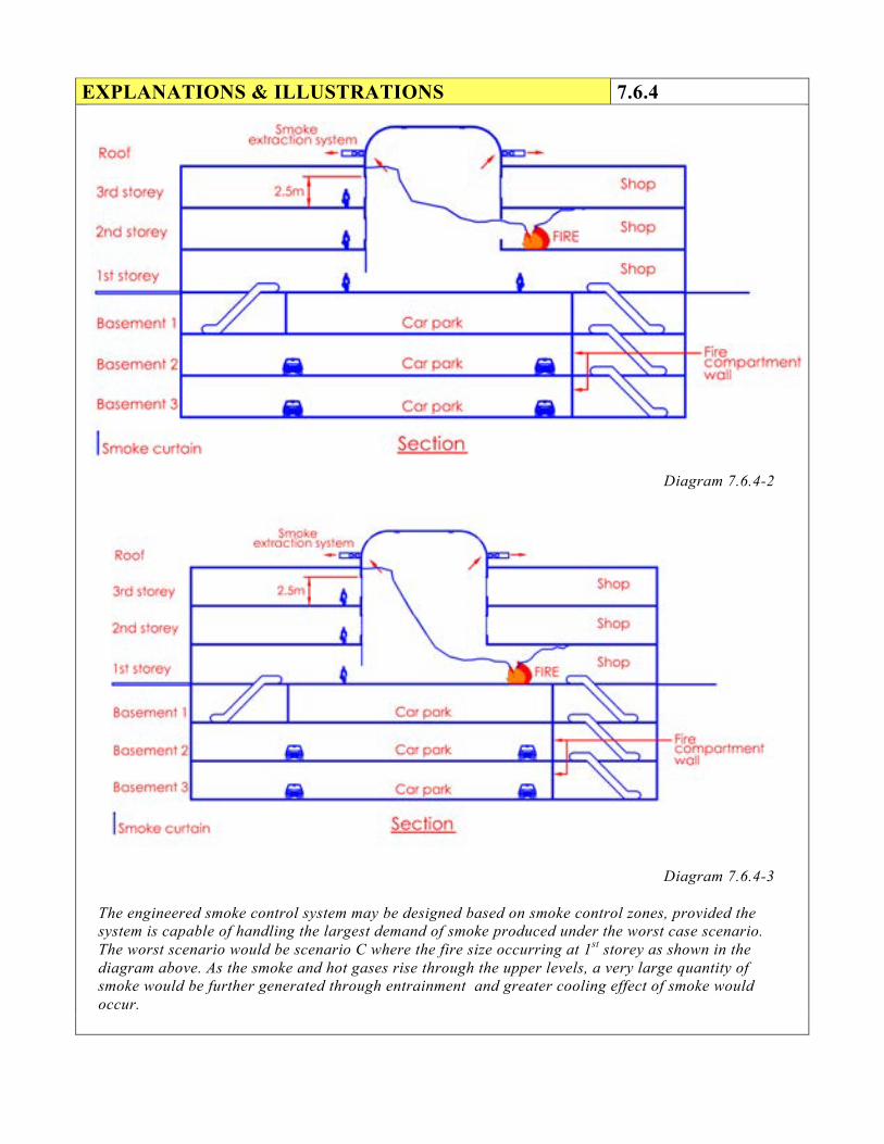
Diagram 7.6.4-2
Diagram 7.6.4-3
The engineered smoke control system may be designed based on smoke control zones, provided the system is capable of handling the largest demand of smoke produced under the worst case scenario. The worst scenario would be scenario C where the fire size occurring at 1st storey as shown in the diagram above. As the smoke and hot gases rise through the upper levels, a very large quantity of smoke would be further generated through entrainment and greater cooling effect of smoke would occur.
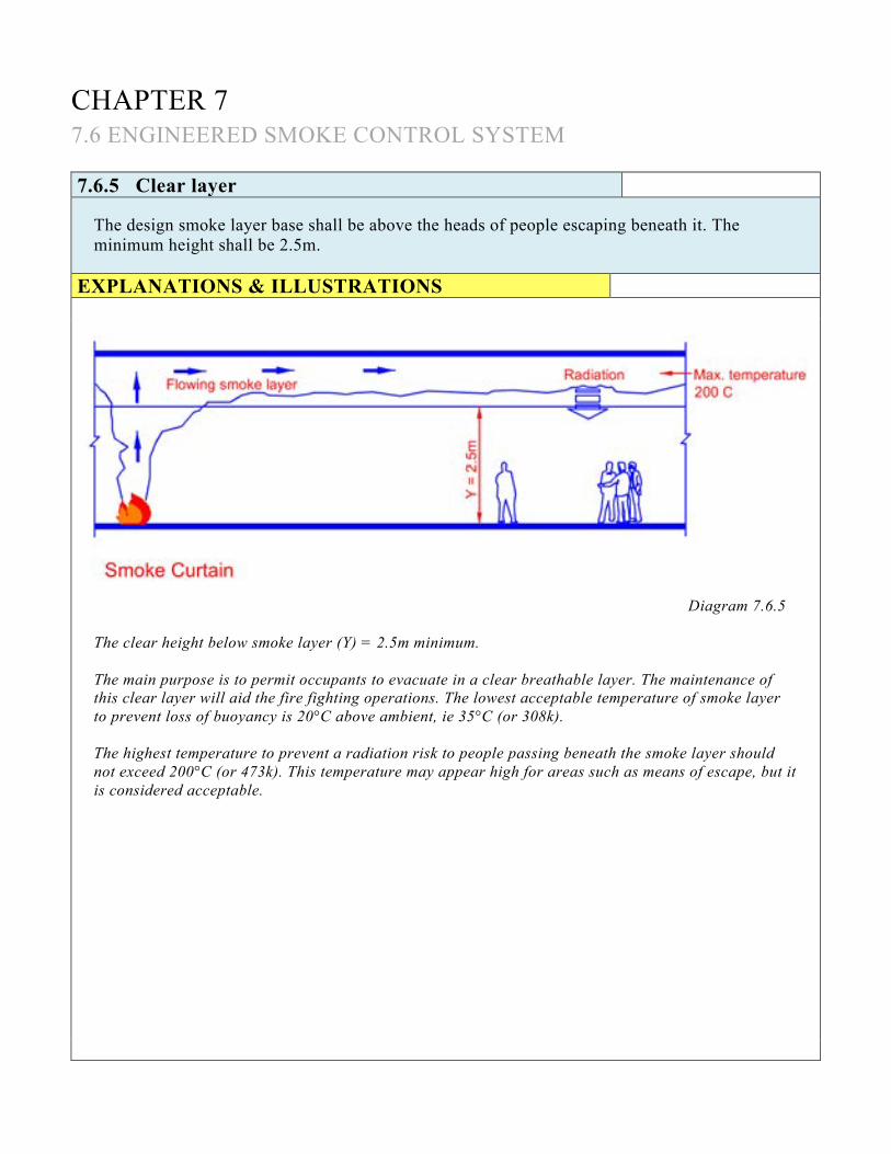
CHAPTER 7 7.6 ENGINEERED SMOKE CONTROL SYSTEM 7.6.5 Clear layer
The design smoke layer base shall be above the heads of people escaping beneath it. The minimum height shall be 2.5m.
EXPLANATIONS & ILLUSTRATIONS
Diagram 7.6.5
The clear height below smoke layer (Y) = 2.5m minimum. The main purpose is to permit occupants to evacuate in a clear breathable layer. The maintenance of this clear layer will aid the fire fighting operations. The lowest acceptable temperature of smoke layer to prevent loss of buoyancy is 20°C above ambient, ie 35°C (or 308k). The highest temperature to prevent a radiation risk to people passing beneath the smoke layer should not exceed 200°C (or 473k). This temperature may appear high for areas such as means of escape, but it is considered acceptable.

CHAPTER 7 7.6 ENGINEERED SMOKE CONTROL SYSTEM 7.6.6 Smoke reservoir
Smoke reservoirs to prevent the lateral spread of smoke, and to collect smoke for removal shall be of non-combustible construction capable of withstanding smoke temperatures.
EXPLANATIONS & ILLUSTRATIONS
Diagram 7.6.6
Smoke reservoirs could be formed by using either the building’s geometry or by using smoke curtains/shutters/non-combustible downstands, such as fire resisting boards, glazing. The screens, which extend downwards from the roof or ceiling to form the smoke reservoir, should preferable be smoke tight. They should be resistant to the effects of the fire. The main reasons for restricting lateral spread of smoke by providing smoke reservoir are: (a) to prevent damage or even ignition to combustible parts of ceiling lining or service components if
hot smoke layers are allowed to spread uncontrolled over unlimited areas; and
(b) to prevent smoke layer (because of mixing with cold air in the course of lateral travel) become relatively cool and shallow. This will result in roof vents being unable to expel the smoke efficiently. Smoke vents would be most effective if the temperature of the smoke layer is high and that the layer beneath the vent is quite deep, thus developing a reasonable pressure differential to act to expel the smoke through the vent.

CHAPTER 7 7.6 ENGINEERED SMOKE CONTROL SYSTEM 7.6.7 Smoke reservoir size
For cases where smoke is removed from the room of origin the smoke reservoir size for a smoke ventilation system shall not exceed: (a) 2000m² for natural smoke ventilation system.
(b) 2600m² for mechanical smoke ventilation system.
EXPLANATIONS & ILLUSTRATIONS
Diagram 7.6.7
Room of origin includes atria, large shopping floor, rooms or spaces. Large reservoir will present a large surface area to the smoke layer, which can lead to considerable heat losses from it. Smoke control system is therefore designed with maximum specified smoke reservoir size to prevent excessive heat loss from the smoke layer, which leads to loss of its buoyancy for effective smoke venting or exhaust from the building.
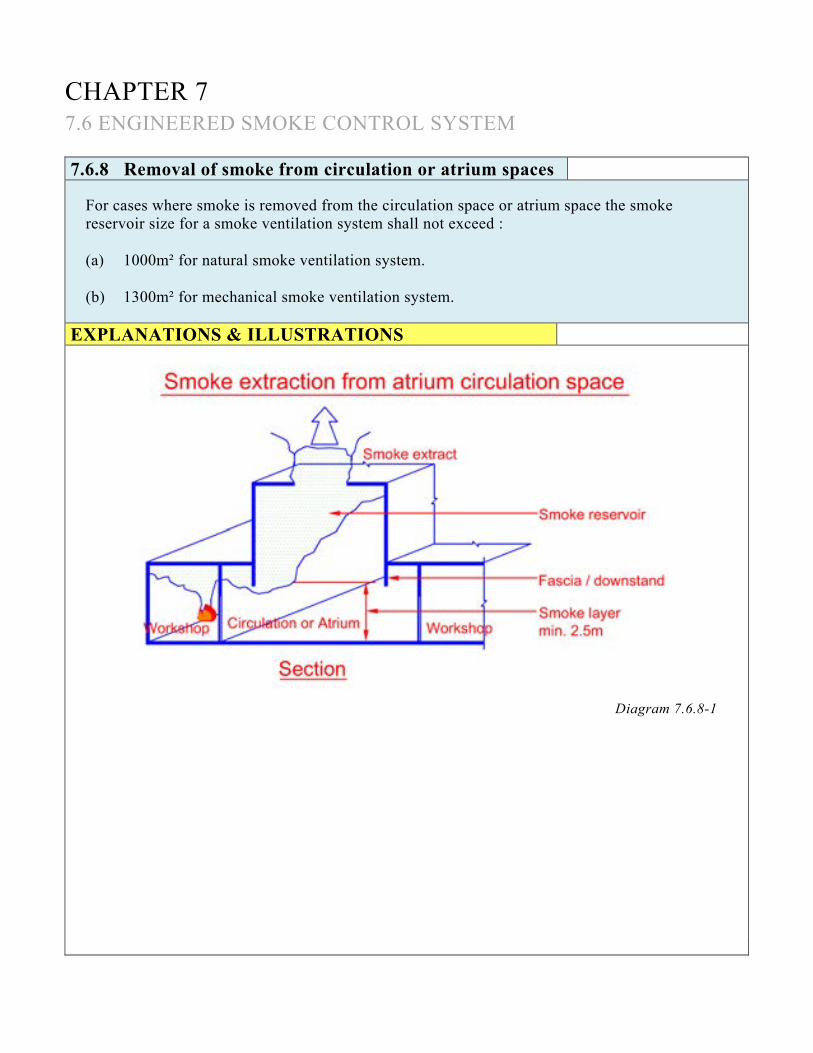
CHAPTER 7 7.6 ENGINEERED SMOKE CONTROL SYSTEM 7.6.8 Removal of smoke from circulation or atrium spaces
For cases where smoke is removed from the circulation space or atrium space the smoke reservoir size for a smoke ventilation system shall not exceed : (a) 1000m² for natural smoke ventilation system. (b) 1300m² for mechanical smoke ventilation system.
EXPLANATIONS & ILLUSTRATIONS
Diagram 7.6.8-1
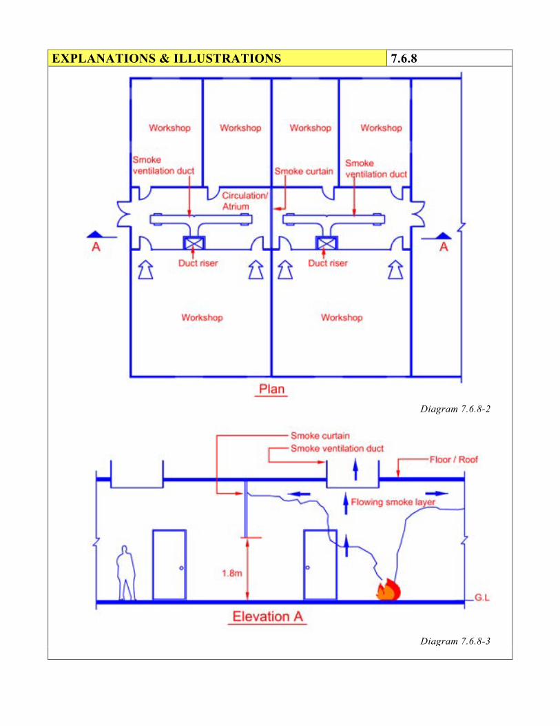
EXPLANATIONS & ILLUSTRATIONS 7.6.8
Diagram 7.6.8-2
Diagram 7.6.8-3

EXPLANATIONS & ILLUSTRATIONS 7.6.8
For cases where smoke is allowed to spill into the circulation or atrium space before extraction takes place, the smoke reservoir sizes are halved. Individual smoke reservoir can be created for circulation or atrium space, subject to 1300m² for mechanical ventilation or 1000m² for natural ventilation. The smoke reservoirs could be formed by using either the building’s geometry or by using smoke curtains/shutters/non-combustible downstands. The depth of any screen used for subdivision shall be taken into account. Screens should terminate at a minimum of 500mm below the smoke layer base. The main reasons for limiting the size of reservoirs are: (a) smoke from a fire leaves a workshop and enters the smoke reservoir in the circulation or atrium
space, it will encounter turbulence and greater mixing occurs which produces more smoke; and
(b) the movement of smoke from workshop into the circulation or atrium space would cause the smoke to lose heat to the surrounding structure through conduction and further loss occurring due to downward radiation. This movement would cause the smoke to lose some of its buoyancy.
For factory, the circulation or atrium space serves as a means of escape for people escaping from the workshop, before exiting to a safe area outside the building. The circulation or atrium space is therefore an additional stage to the escape route, which requires to be protected from the effects of fire and smoke. For warehouse, which is primarily designed for storage, the smoke ventilation system provided would be for the purpose of heat and smoke release from the building. Warehouse should be treated differently from factory. For warehouse, which is used for palletised storage, consideration should be given to the possible collapse of stacks or radiated heat spreading the fire to adjacent stacks. In tall warehouse, which is used for high rack storage, the smoke layer temperature may not go beyond 35°C and therefore, the smoke layer could well go below the level of the storage. Consideration should be given to the existence of ceiling jet occurring in the smoke layer.
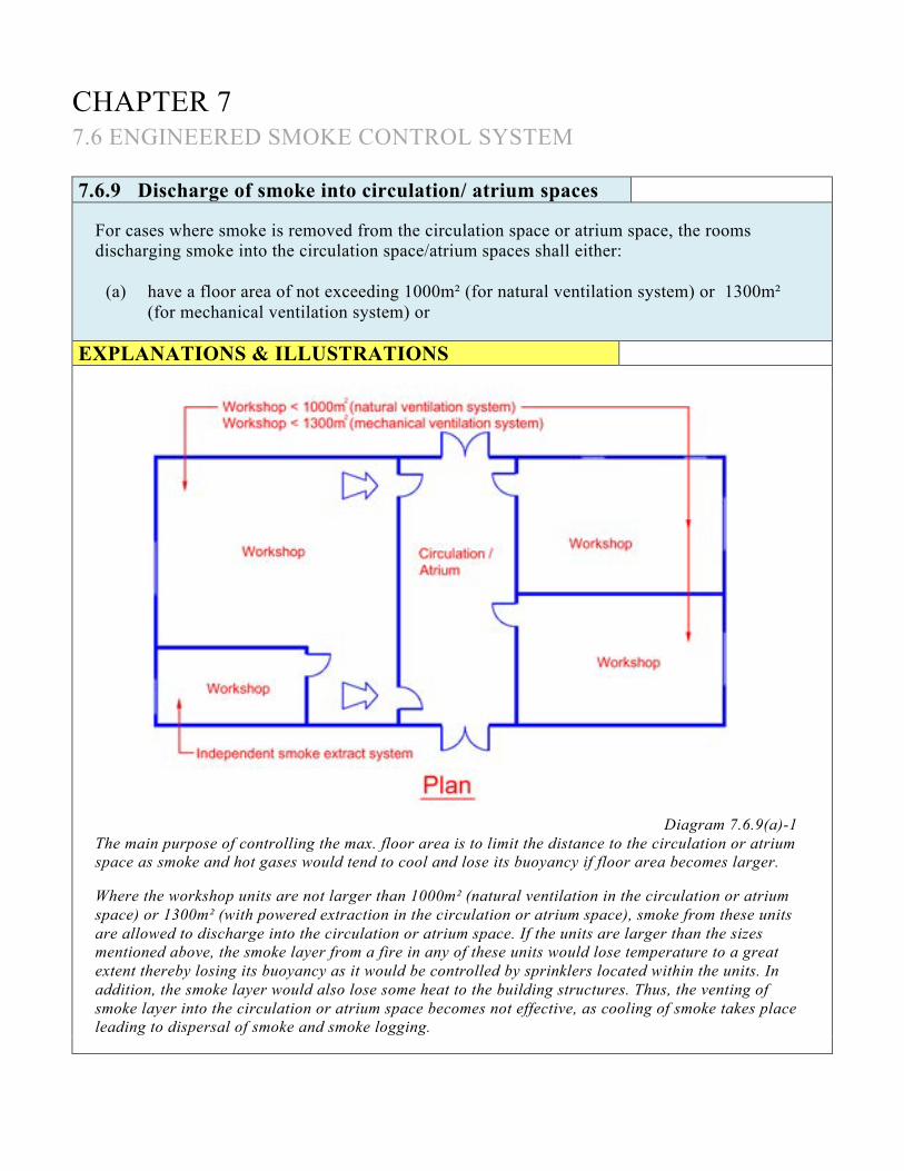
CHAPTER 7 7.6 ENGINEERED SMOKE CONTROL SYSTEM 7.6.9 Discharge of smoke into circulation/ atrium spaces
For cases where smoke is removed from the circulation space or atrium space, the rooms discharging smoke into the circulation space/atrium spaces shall either:
(a) have a floor area of not exceeding 1000m² (for natural ventilation system) or 1300m² (for mechanical ventilation system) or
EXPLANATIONS & ILLUSTRATIONS
Diagram 7.6.9(a)-1 The main purpose of controlling the max. floor area is to limit the distance to the circulation or atrium space as smoke and hot gases would tend to cool and lose its buoyancy if floor area becomes larger. Where the workshop units are not larger than 1000m² (natural ventilation in the circulation or atrium space) or 1300m² (with powered extraction in the circulation or atrium space), smoke from these units are allowed to discharge into the circulation or atrium space. If the units are larger than the sizes mentioned above, the smoke layer from a fire in any of these units would lose temperature to a great extent thereby losing its buoyancy as it would be controlled by sprinklers located within the units. In addition, the smoke layer would also lose some heat to the building structures. Thus, the venting of smoke layer into the circulation or atrium space becomes not effective, as cooling of smoke takes place leading to dispersal of smoke and smoke logging.

EXPLANATIONS & ILLUSTRATIONS 7.6.9(a)
Diagram 7.6.9(a)-2
The combined floor area of multiple shops should not exceed 1000m2 or 1300m2 (power extraction) fronting circulation or atrium space. It is acceptable to use screen to channel the smoke from the shop into the circulation or atrium space, subject to maximum 14m separation between channel screens.

(b) be subdivided such that smoke is vented to the circulation space or atrium only from
part of the room with floor area not exceeding 1000m² (for natural ventilation system) or 1300m² (for mechanical ventilation system) that are adjacent to the circulation space or atrium. However, the remainder of the room needs to be provided with an independent smoke ventilation system(s).
EXPLANATIONS & ILLUSTRATIONS 7.6.9
Diagram 7.6.9(b)
Where a large workshop is extracted separately from the circulation/atrium space, it can have ceiling reservoirs up to twice the area permitted in the circulation/atrium space; 2000m² (natural ventilation system) or 2600 m² (mechanical ventilation system) as no smoke is allowed to spill into the circulation/atrium space.

CHAPTER 7 7.6 ENGINEERED SMOKE CONTROL SYSTEM 7.6.10 Length of smoke reservoir
The maximum length of the smoke reservoir shall not exceed 60m. EXPLANATIONS & ILLUSTRATIONS
Figure 1
Figure 2

EXPLANATIONS & ILLUSTRATIONS 7.6.10
Figure 3
Figure 4
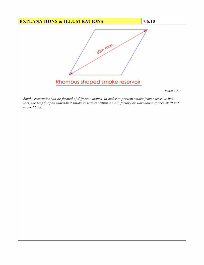
EXPLANATIONS & ILLUSTRATIONS 7.6.10
Figure 5
Smoke reservoirs can be formed of different shapes. In order to prevent smoke from excessive heat loss, the length of an individual smoke reservoir within a mall, factory or warehouse spaces shall not exceed 60m.

CHAPTER 7 7.6 ENGINEERED SMOKE CONTROL SYSTEM 7.6.11 Stagnant regions
Adequate arrangement(s) shall be made in each smoke reservoir for the removal of smoke in a way that will prevent the formation of stagnant regions.
EXPLANATIONS & ILLUSTRATIONS
Diagram 7.6.11-1
A stagnant region occurred in a long smoke reservoir when venting or extraction is not properly distributed or when circulation/atrium or mall has a closed end.

EXPLANATIONS & ILLUSTRATIONS 7.6.11
Diagram 7.6.11-2
A stagnant region could also be formed by physical obstruction in the smoke reservoir eg. Beam. If a smoke layer is stagnant, it willl cool down and will mix into the air below. If the air space under a smoke layer is stagnant, it will tend to fill up with hazy smoke of sufficient density to affect visibility. Venting or extraction should be well distributed in the smoke layer or smoke reservoir. The air inlets at low level should also be well distributed so that the air, which is being drawn in will purge as much of the low-level clear air as possible.

CHAPTER 7 7.6 ENGINEERED SMOKE CONTROL SYSTEM 7.6.12 Stagnant regions
Owing to practical limitation, a smoke ventilation system shall have: (a) a maximum mass flow not exceeding 175kg/s; and (b) a minimum smoke layer temperature of 18oC above ambient.
EXPLANATIONS & ILLUSTRATIONS
No illustration. (a) It has commonly been found that very large exhaust rates, typically larger than about 175kg/s,
become impractical as large and heavy fans or ventilators would be required. Large and heavy fans or ventilators required additional structural supports.
(b) A minimum design temperature is required to maintain stability of the smoke layer. Smoke layers
which have temperatures approaching that of the replacement air will have a tendency to mix with this air rather than to float above it.
The stipulated minimum design layer temperature is intended to be high enough to allow safe operation of the system for fires which are smaller than the full design size.

CHAPTER 7 7.6 ENGINEERED SMOKE CONTROL SYSTEM 7.6.13
Replacement air shall be by natural means drawing air directly from the external.
(a) Replacement air velocity
The design replacement air discharge velocity shall not exceed 5m/s to prevent the escapees being hindered by the air flow.
(b) Distance from exhaust air discharge
Replacement air intake shall be sited at least 5m away from any exhaust air discharge. (c) Replacement discharge position
Replacement air shall be discharged at a low level, at least 1.5m beneath the designed smoke layer, to prevent “fogging” of the lower clear zone.
(d) Siting of inlets
Where the inlet cannot be sited at least 1.5m below the smoke layer, a smoke curtain or a barrier shall be used to prevent replacement air distorting the smoke layer.
(e) Where replacement air is taken through inlet air ventilators or doorways, devices shall be
incorporated to automatically open such inlet ventilators and doors to admit replacement air upon activation of the smoke ventilation system.
(f) Replacement air for engineered smoke control system
Where the automatic roller shutters are used at replacement air inlets in the design and installation of engineered smoke control system, it shall be of perforated type having the required effective free area for the effective operation of the engineered smoke control system.

EXPLANATIONS & ILLUSTRATIONS 7.6.13
Diagram 7.6.13-1
The use of fan-driven inlet air supply can give problems with mechanical extraction. This is because the warmed air taken out will have a greater volume than the inlet air. As the fire grows and declines, the mismatch in volume between the inlet air and the extracted fire warmed air will also change. This can result in significant pressure differences appearing across any doors on the escape routes. Hence, to avoid this “push-pull” effect, replacement air shall be drawn by natural means.
Diagram 7.6.13-2 The interactive between an air-inlet (eg a door) and a reservoir
A moving airstream in contact with a region of stationary air (or smoke, or gas) will have a lower pressure than the stationary air – this is the Venturi effect. Hence, a moving airstream will attract the stationary air towards itself. The force of attraction increases with increasing velocity of the airstream. In diagram 7.6.13 – 2, the clean airstream flowing through the door attracts the smoke towards itself. The smoke reservoir base follows the surface of constant pressure, and bulges downwards near the door. Unless the reservoir base is high enough above the door (at least 1.5m), the smoke base will come just below the top of the door.

EXPLANATIONS & ILLUSTRATIONS 7.6.13
Diagram 7.6.13-3
Where inlets (e.g. door) cannot be sited at least 1.5m below the base of smoke layer, either a smoke curtain or a horizontal shelf could be used to prevent inlet air distorting the smoke layer. Diagram 7.6.13 – 3 shows a smoke-restraining curtain set back from the door. The curtain’s bottom edge is higher than the door. The incoming air stream will increase in vertical section as it travels from the door to beneath the curtain, and so will slow down. There are fewer tendencies to pull down the smoke-base. There is less turbulence at the smoke/air interface mixing smoke into the air stream and any such mixed smoke is at a higher level. The curtain shall be more than 3m away from the door.
Diagram 7.6.13-4 Using a horizontal shelf instead of a smoke curtain, which permits the same air expansion and gives the same results. The shelf-edge should be more than 3m away from the door.

CHAPTER 7 7.6 ENGINEERED SMOKE CONTROL SYSTEM 7.6.14 Perforated ceiling
For cases where the smoke reservoir is above the false ceiling, the ceiling shall be of perforated type with at least 25% opening.
EXPLANATIONS & ILLUSTRATIONS
Diagram 7.6.14
If the smoke reservoir incorporates a false ceiling, then the space above the false ceiling may be included in the depth of the smoke reservoir provided the screens forming the reservoir extend up to the structural ceiling, the perforations in the false ceiling are at least 25% of the total area of the reservoir, and the space occupied by services etc. above the ceiling is not greater than 50% of the volume above the ceiling.

CHAPTER 7 7.6 ENGINEERED SMOKE CONTROL SYSTEM 7.6.15 Emergency power supply
The smoke ventilation system shall be provided with secondary source of power supply.
EXPLANATIONS & ILLUSTRATIONS
No illustration. All the associated systems/mechanisms, like the door venting actuators, are to be back-up by secondary power supply. This is necessary, as these devices are not incorporated with “standby” batteries that can operate the mechanisms to function as required in the emergency mode.

CHAPTER 7 7.6 ENGINEERED SMOKE CONTROL SYSTEM 7.6.16 Mode of activation 7
The smoke ventilation system shall be activated by smoke detectors located in the smoke control zone. Use of smoke detectors for activation must be carefully designed so that accidental or premature activation of smoke detectors on a non-fire zone due to smoke spills or spread from other areas must be avoided.
EXPLANATIONS & ILLUSTRATIONS
Diagram 7.6.16 Scenario A : A fire occurring at 3rd storey failed to activate the smoke detector at that level owing to its poor location. Instead, smoke is allowed to spill into the atrium void and smoke control system for the building is activated. This would release all the smoke curtains overlooking the atrium void, including the fire floor, which is not correct. As a result, smoke and heat will be retained in the fire floor. The correct sequence of events should be that the smoke detectors at the fire floor should be activated first, thereby locking the smoke curtain, while releasing all smoke curtains in other parts of the building. Scenario B : A fire occurring at the atrium floor caused smoke to spill and activate the smoke detector in 2nd storey. The smoke curtain will remain locked but at other floors, the smoke curtains will descend down. As a result, part of 2nd storey will be smoke logged. Smoke control system reacts to the first signal sent by the detector. To overcome the above problem, it is recommended that closer spacing of smoke detectors, closer than the permitted limit in SS CP10, be adopted and that the detectors should be placed correctly in close proximity of the atrium void.

CHAPTER 7 7.6 ENGINEERED SMOKE CONTROL SYSTEM 7.6.17
Provision of activating smoke detectors shall comply with SS CP 10.
EXPLANATIONS & ILLUSTRATIONS
No illustration. (See illustration under Cl.7.6.14) The smoke ventilation system shall operate automatically upon detection of smoke by smoke detector placed strategically at the smoke control zone.The layout of smoke detectors shall comply with CP 10.
CHAPTER 7 7.6 ENGINEERED SMOKE CONTROL SYSTEM 7.6.18 Manual activation
A remote manual activation and control switches as well as visual indication of the operation status of the smoke ventilation system shall also be provided at the fire command centre and where there is no fire command centre, at main fire indicator board.
EXPLANATIONS & ILLUSTRATIONS
No illustration. The provision of remote manual activation and control switches located at Fire Command Centre or Fire Alarm Panel would permit better monitoring of the smoke ventilation system. In the event of the smoke detectors malfunctioning, the atrium smoke extract system can be activated by a manual switch, which performs the function of the smoke detectors in actuating the associated devices for the isolation and extraction of the smoke from the affected areas.

CHAPTER 7 7.6 ENGINEERED SMOKE CONTROL SYSTEM 7.6.19 Shut down of other air conditioning & ventilation
systems
Except for ventilation systems in Cl.5.2.1(g) and (h), all other air-conditioning and ventilation systems within the areas served shall be shut down automatically upon activation of the smoke ventilation system.
EXPLANATIONS & ILLUSTRATIONS
No illustration. Mechanical ventilation to the following room or space should not be affected: (i) exit staircases and exit passageways;
(ii) smoke-stop and fire fighting lobbies;
(iii) areas of refuge within the same building;
(iv) basement carparks;
(v) fire command centres;
(vi) flammable liquid/gas storage room;
(vii) emergency generator;
(viii) engine driven fire pump.
AHUs serving the affected smoke zone are to be shut down automatically upon activation of the smoke ventilation system, while the rest may continue to function.
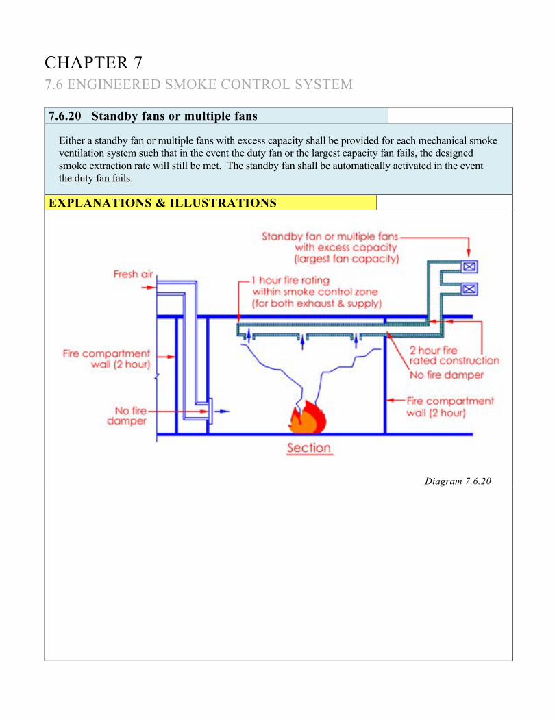
CHAPTER 7 7.6 ENGINEERED SMOKE CONTROL SYSTEM 7.6.20 Standby fans or multiple fans
Either a standby fan or multiple fans with excess capacity shall be provided for each mechanical smoke ventilation system such that in the event the duty fan or the largest capacity fan fails, the designed smoke extraction rate will still be met. The standby fan shall be automatically activated in the event the duty fan fails.
EXPLANATIONS & ILLUSTRATIONS
Diagram 7.6.20

CHAPTER 7 7.6 ENGINEERED SMOKE CONTROL SYSTEM 7.6.21
Fans shall be capable of operating at 250°C for 2 hours.
EXPLANATIONS & ILLUSTRATIONS
No illustration. The fans shall have the capability to handle high temperature smoke at 250°C and remain operational for a period of not less than 2 hours.
CHAPTER 7 7.6 ENGINEERED SMOKE CONTROL SYSTEM 7.6.22 Protected circuits
The fans and associated smoke control equipment shall be wired in protected circuits designed to ensure continued operation in the event of the fire.
EXPLANATIONS & ILLUSTRATIONS
No illustration. Since the smoke control system is installed to remove smoke and heat from the building to aid evacuation of occupants and fire fighting operations, the system’s circuits shall be protected to ensure operational reliability and sustained operation during fire emergency.

CHAPTER 7 7.6 ENGINEERED SMOKE CONTROL SYSTEM 7.6.23 Electrical supply
The electrical supply to the fans shall, in each case, be connected to a sub-main circuit exclusive thereto after the main isolator of the building. The cables shall be of at least 1-hour fire resistance in accordance with SS 299.
EXPLANATIONS & ILLUSTRATIONS
No illustration. The main purpose is to ensure that the electrical supply to the fans could be maintained continuously for at least 1 hour.

CHAPTER 7 7.6 ENGINEERED SMOKE CONTROL SYSTEM 7.6.24
Smoke ventilation ducts (both exhaust and replacement air ducts) shall be of at least 1 hour fire resistance. Where a duct passes through other fire compartment of higher rating, the duct shall be constructed to have the rating as that of the compartment. The rating shall apply to fire exposure from both internal and external of the duct or structure and the duct shall also comply with sub-cl.7.1.1(j).
EXPLANATIONS & ILLUSTRATIONS
No illustration. (See illustration under cl.7.6.20).
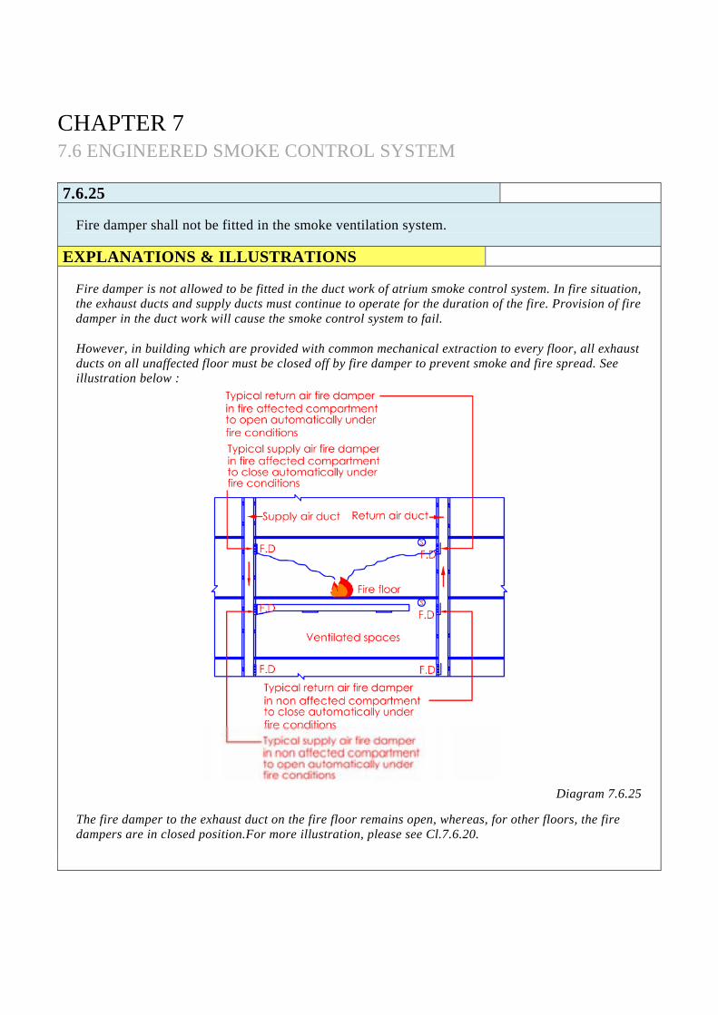
CHAPTER 7 7.6 ENGINEERED SMOKE CONTROL SYSTEM 7.6.25
Fire damper shall not be fitted in the smoke ventilation system.
EXPLANATIONS & ILLUSTRATIONS
Fire damper is not allowed to be fitted in the duct work of atrium smoke control system. In fire situation, the exhaust ducts and supply ducts must continue to operate for the duration of the fire. Provision of fire damper in the duct work will cause the smoke control system to fail.
However, in building which are provided with common mechanical extraction to every floor, all exhaust ducts on all unaffected floor must be closed off by fire damper to prevent smoke and fire spread. See illustration below :
Diagram 7.6.25
The fire damper to the exhaust duct on the fire floor remains open, whereas, for other floors, the fire dampers are in closed position.For more illustration, please see Cl.7.6.20.

CHAPTER 7 7.6 ENGINEERED SMOKE CONTROL SYSTEM 7.6.26
The time taken for the smoke ventilation system within a smoke zone to be fully operational shall not exceed 60 seconds from system activation.
EXPLANATIONS & ILLUSTRATIONS
No illustration.

CHAPTER 7 7.6 ENGINEERED SMOKE CONTROL SYSTEM 7.6.27 Fail-safe system
For natural smoke ventilation system the natural ventilators shall be : (a) in the “open” position in the event of power/system failure; and
(b) positioned such that they will not be adversely affected by positive wind pressure.
EXPLANATIONS & ILLUSTRATIONS
Diagram 7.6.27
Wrong positioning of roof ventilators can cause the wind to be deflected into the atrium roof space, thereby pushing the smoke downward into the building. Roof adjacent to tall buildings could be subjected to positive pressure. It is for the designer to prove that his design will be satisfactory.

CHAPTER 7 7.6 ENGINEERED SMOKE CONTROL SYSTEM 7.6.28
Natural exhaust ventilation shall not be used together with powered smoke exhaust ventilation. EXPLANATIONS & ILLUSTRATIONS
Diagram 7.6.28
The combination of natural exhaust ventilation and powered smoke exhaust ventilation in a building would create complications on the design of the distance between the bottom of the smoke reservoir and the floor and also the extent of the depth of the smoke reservoir.

CHAPTER 7 7.6 ENGINEERED SMOKE CONTROL SYSTEM 7.6.29 Smoke curtain
All smoke curtains where required, unless permanently fixed in position, shall be brought into position automatically to provide adequate smoke-tightness and effective depth.
EXPLANATIONS & ILLUSTRATIONS
No illustration. The intent of the smoke curtain is to contain the smoke and to prevent spillage of smoke to other areas. All smoke curtains are required to be under the PSB Product Listing Scheme.

CHAPTER 7 7.6 ENGINEERED SMOKE CONTROL SYSTEM 7.6.30 Obstruction to means of escape
Smoke curtain or other smoke barrier at any access route forming part of or leading to a means of escape shall not in their operational position obstruct the escape of people through such route.
EXPLANATIONS & ILLUSTRATIONS
Diagram 7.6.30 Upon activation of smoke detector, the smoke curtain is automatically unfurled from its roller under gravity fall to impede smoke flow. The dropped curtains limit the area of smoke spread, maintain visibility and tenable conditions for escape purposes. Smoke curtain in operation should not obstruct the escape routes. The clear height of smoke curtain across the escape routes should not be lower than 1.8m from its finished floor level.

CHAPTER 7 7.6 ENGINEERED SMOKE CONTROL SYSTEM 7.6.31 Smoke or chanelling screens
Where glass walls or panels are being used as smoke screens to form a smoke reservoir or as channelling screens, they shall be able to withstand the design highest temperature.
EXPLANATIONS & ILLUSTRATIONS
Diagram 7.6.31-1 Wired glass or tempered glass could be used as smoke screen to form smoke reservoir, provided they are able to meet the designed highest temperature. Glass walls or panels acting as smoke screen shall not be of sliding, louvers or openable type.

EXPLANATIONS & ILLUSTRATIONS 7.6.31
Diagram 7.6.31-2 Smoke screens, which are to meet the designed highest temperature, could be used to form smoke reservoirs to limit lateral spread. Smoke channelling screens are used to channel smoke away from the origin of fire to smoke reservoirs where extraction can be carried out, or away from the building entrance canopies to the external open space as shown above. It is recommended that the spacing between channelling screens should not be more than 14m so as to prevent lateral spread of smoke and excessive cooling.

CHAPTER 7 7.6 ENGINEERED SMOKE CONTROL SYSTEM
7.6.32
All smoke control equipment (including smoke curtains) shall be supplied and installed in accordance with the accepted standards eg BS 7346.
EXPLANATIONS & ILLUSTRATIONS
No illustration. Fixed screen shall be constructed of non-combustible materials capable of resisting the highest design temperatures. Automatic retractable smoke curtains are required to comply with BS 7346 and listed under PSB Product Listing Scheme.
CHAPTER 7 7.7 AUDITORIUM (USED OR INTENDED FOR USE AS CINEMA,
CONCERT HALL, PERFORMANCE THEATRE) SMOKE CONTROL SYSTEM
7.7.1
Provision of smoke vents having 2.5% of the floor area shall be provided to auditorium which is not sprinkler protected and to auditorium having floor area more than 500m2, if sprinkler protected. The opening of the smoke vents shall be by automatic device.
EXPLANATIONS & ILLUSTRATIONS
No illustration.

CHAPTER 7 7.7 AUDITORIUM (USED OR INTENDED FOR USE AS CINEMA,
CONCERT HALL, PERFORMANCE THEATRE) SMOKE CONTROL SYSTEM
7.7.2
In place of smoke vents, an engineered smoke control system would be considered as acceptable. EXPLANATIONS & ILLUSTRATIONS
Diagram 7.7.2
Auditorium includes cineplex in shopping centres, ballroom, convention hall, lecture theatre, exhibition centre, large meeting room, large conference room, room with mass seating which are windowless shall comply with the above requirement. Smoke vents having 2.5 % of the floor area are to be provided for: (a) windowless auditorium not protected by sprinkler system;
(b) windowless auditorium exceeding 500m2 protected by sprinkler system;
(c) in lieu of smoke vents, engineered smoke control system is to be provided.