Embed Size (px)
Citation preview
97
CHAPTER 6
OPTICAL SENSORS AND SPECIALTY FIBERS
Donald B. Keck
INTRODUCTION
The “Information Age” is upon us. We generate, process, store, display, and transmit information in ever increasing amounts. Sensing and measuring is one aspect of information generation that will become an increasingly important activity in the coming years.
In the broadest context, the field of optical sensing includes both imaging and nonimaging sensors. The imaging category includes both proximity sensing and remote sensing; it encompasses all of the technology activity in charge-coupled device (CCD) focal plane arrays, for example. Imaging and remote sensing are each distinct fields in themselves and are beyond the scope of this study. This chapter focuses on the field of nonimaging sensor technology.
Work on nonimaging optical sensor technology began building momentum about a decade ago. Figure 6.1 shows the chronology of papers presented around the world in this broad area. Further examination of the publication data indicates that optical sensing involving fiber constitutes almost 93% of the work on nonimaging sensors. As a consequence, in benchmarking this technology it is important to examine activity in specialty fibers.
Breaking the work in fiber-optic sensor technology into even smaller subsets, one finds not only a very diverse field but a very fragmented marketplace as well. The myriad aspects of transmitting light through guiding structures results in multiple methods of sensing and measuring physical and chemical quantities; similarly, application of these techniques in the marketplace is found in many niches.
6. Optical Sensors and Specialty Fibers
Fig. 6.1. Fiber-optic and optical sensor publication chronology (Dialog File 4, INSPEC Database).
Much of the optical sensor work is being done at universities and small companies; as a result, the current cost picture for most of the sensors being produced and studied is that of low-volume, high-cost manufacturing. Large companies are tending to watch and wait for emergence of a large application requiring their expertise in high-volume manufacturing before committing resources. All the benefits envisioned by workers in this field, and there are many, have not yet resulted in the scale-up required for low-cost, high-volume manufacturing. What is likely required is a convergence to a single technology platform where many sensor types can be produced from a relatively small number of component building blocks. While that concept is not new, and there seems to be a widely held view that the components of optical fiber communications can provide the necessary ingredients, to date that convergence has not happened, in North America, Asia, or Europe.
SUMMARY OF JAPANESE AND U.S. OPTICAL SENSOR ACTIVITIES
Optical sensing R&D can be broken into twelve topical categories: ten sensor types (chemical, temperature, strain, biomedical, electrical and magnetic, rotation, vibration, displacement, pressure, and flow) and two general categories (enabling science and components, and networks and instrumentation). The status of the optical fibers used in sensors is a distinct, but related, topic of interest to this study.
In both Japan and the United States there is a growing interest in optical sensing. Japan’s Optoelectronics Industry and Technology Development Association (OITDA) indicates the sensor market is currently worth approximately $920 million a year (OITDA 1994). The North American Optoelectronics Industry Development Association (OIDA, private communication with the author) predicts a growth potential reaching approximately $5 billion by the first decade of the next century. Currently, the largest activities in the sensor market are chemical gas sensing, medical pressure sensing, automotive rotation and direction sensing, and temperature sensing. The main growth areas are expected to be chemical sensing, mostly related to environmental sensing, and biomedical sensing, oriented at first toward point-of-care sensing, but evolving to home sensing. Strain sensing associated with “smart structures” is also expected to be an area of considerable growth.
Optical sensor researchers have already demonstrated and/or delivered a technique for sensing virtually every measurand of interest. For the most part, they have based their work on optical fiber components and techniques resulting from the optical fiber communications revolution. Sensitivity levels of optical sensors generally exceed the values required by present applications. In addition to sensitivity, optical sensors also offer freedom from electrical and magnetic interference. As with most sensitive
98

Donald B. Keck
measurement techniques, however, interference from other competing effects can often be a problem — for example, a strain sensor may be temperature-dependent. Much work has been done to mitigate these competing effects, and many of these interferences have been overcome. Research trends indicate that the most promising sensors are interferometric types of sensors, fiber Bragg grating sensors, and evanescent wave sensors, including two-photon types.
A study of the published data and a review of the JTEC panel’s site visits leads to several conclusions of national interest regarding this technology. Leading research is being done primarily in the United States. The U.S. “national laboratories” such as the Naval Research Laboratory (NRL) and the National Institute of Standards and Technology (NIST) have done much of the leading work.
In the commercial arena, the relative national standings are mixed. The United States has commercial leadership in chemical, strain, biomedical, and pressure sensing, while Japanese companies lead in commercial rotation and electric and magnetic sensing. The U.S. commercial arena is populated with many small companies, a number of which have recently been purchased by foreign national companies; for example, the French company Photonetics purchased Metricor, and the Swedish company ABB purchased the Westinghouse optical sensor group. In Japan, the optical sensor effort comes mostly from divisions of large companies such as Hitachi Cable and Sumitomo Electric. These companies have focused on potentially high-volume applications with lower performance requirements; a notable example is Hitachi’s fiber-optic gyroscope (FOG), designed for high-volume automotive applications.
OPTICAL SENSOR TECHNOLOGIES
Measurands and Sensor Categories
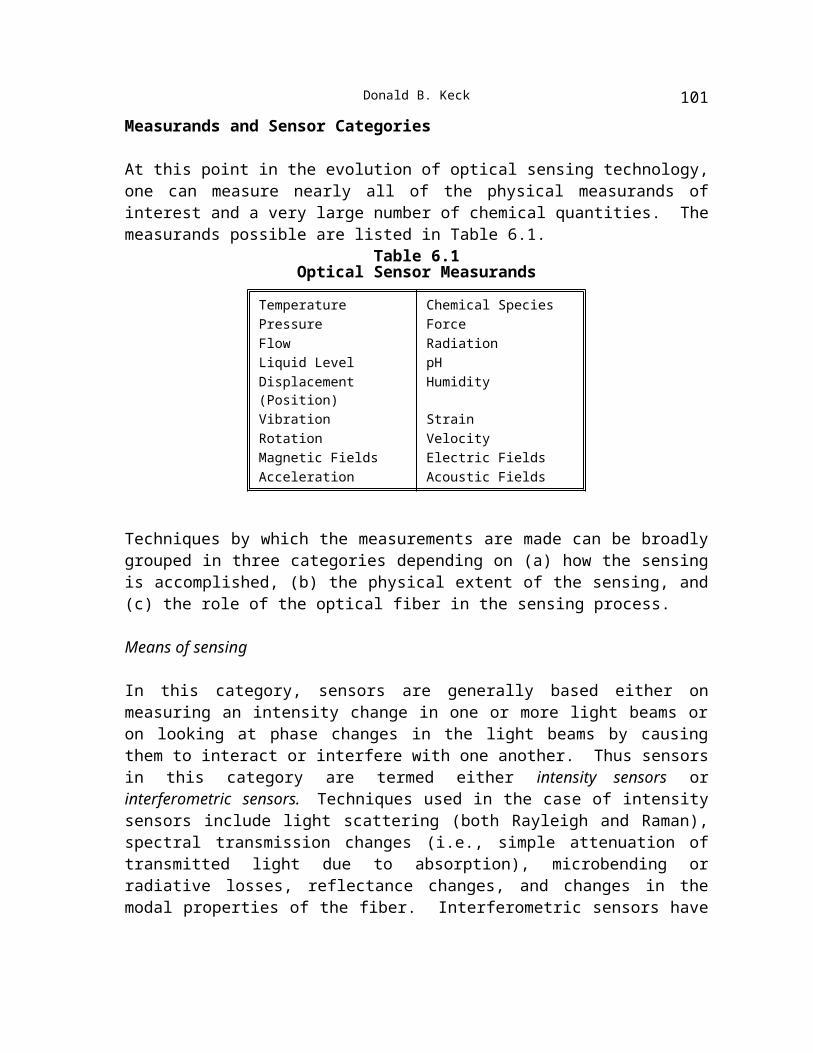
At this point in the evolution of optical sensing technology, one can measure nearly all of the physical measurands of interest and a very large number of chemical quantities. The measurands possible are listed in Table 6.1.
Table 6.1Optical Sensor Measurands
Temperature Chemical SpeciesPressure ForceFlow RadiationLiquid Level pHDisplacement (Position) HumidityVibration StrainRotation VelocityMagnetic Fields Electric FieldsAcceleration Acoustic Fields
99
6. Optical Sensors and Specialty Fibers
Techniques by which the measurements are made can be broadly grouped in three categories depending on (a) how the sensing is accomplished, (b) the physical extent of the sensing, and (c) the role of the optical fiber in the sensing process.
Means of sensing
In this category, sensors are generally based either on measuring an intensity change in one or more light beams or on looking at phase changes in the light beams by causing them to interact or interfere with one another. Thus sensors in this category are termed either intensity sensors or interferometric sensors. Techniques used in the case of intensity sensors include light scattering (both Rayleigh and Raman), spectral transmission changes (i.e., simple attenuation of transmitted light due to absorption), microbending or radiative losses, reflectance changes, and changes in the modal properties of the fiber. Interferometric sensors have been demonstrated based upon the magneto-optic, the laser-Doppler, or the Sagnac effects, to name a few
Extent of sensing
This category is based on whether sensors operate only at a single point or over a distribution of points. Thus, sensors in this category are termed either point sensors or distributed sensors. In the case of a point sensor, the transducer may be at the end of a fiber the sole purpose of which is to bring a light beam to and from the transducer. Examples of this sensor type are interferometers bonded to the ends of fibers to measure temperature and pressure. In the case of a distributed sensor, as the name implies, sensing is performed all along the fiber length. Examples of this sensor type are fiber Bragg gratings distributed along a fiber length to measure strain or temperature.
Role of optical fiber
Further distinction is often made in the case of fiber sensors as to whether measurands act externally or internally to the fiber. Where the transducers are external to the fiber and the fiber merely registers and transmits the sensed quantity, the sensors are termed extrinsic sensors. Where the sensors are embedded in or are part of the fiber — and for this type there is often some modification to the fiber itself — the sensors are termed internal or intrinsic sensors. Examples of extrinsic sensors are moving gratings to sense strain, fiber-to-fiber couplers to sense displacement, and absorption cells to sense chemistry effects. Examples of intrinsic sensors are those that use microbending losses in the fiber to sense strain, modified fiber claddings to make spectroscopic measurements, and counter-propagating beams within a fiber coil to measure rotation.
Today, most of the measurands in Table 6.1 can be sensed by either intensity or interferometric techniques and as either point or distributed effects. A wide variety of physical phenomena are used to actually sense the quantity to be measured.
100
Donald B. Keck
Advantages and Disadvantages of Optical Sensors
R&D in the optical sensor field is motivated by the expectation that optical sensors have significant advantages compared to conventional sensor types, in terms of their properties. Table 6.2 lists some of the advantages of optical over nonoptical sensors.
Table 6.2Advantages of Optical Sensors
Greater Sensitivity Wide Dynamic RangeElectrical Passiveness Both Point and Distributed ConfigurationFreedom from Electromagnetic Interference Multiplexing Capabilities
Taking advantage of the capacity of optical fibers to send and receive optical signals over long distances, a current trend is to create networks of sensors, or sensor arrays. This avoids having to convert between electronics and photonics separately at each sensing site, thereby reducing costs and increasing flexibility.
A difficulty of all sensors, both optical and nonoptical, is interference from multiple effects. A sensor intended to measure strain or pressure may be very temperature-sensitive. Intense R&D over the last five years to provide means for distinguishing between various effects has been conducted for optical sensors. Considerable progress has been made, as will be discussed below.
Publication and Patent Trends
Figure 6.2 shows both the publication and the patent chronology for fiber and optical sensors combined. As indicated earlier, most sensors today involve the use of optical fibers somewhere in the technique and are referred to as optical fiber sensors. Optical sensors make use of the same physical phenomena to perform their sensing operation but involve no optical fiber. They instead rely on lens or mirror systems to transmit and manipulate the beams of light used in their sensing process. The fiber and optical sensors field has been active slightly over a decade, with the patent record beginning earlier, as might be expected, and showing growth similar to that of publications.
Fig. 6.2. Fiber and optical sensor publication and patent chronology (Dialog File 4; Dialog File 347 [Japan Patent Office/JAPIO Database]; and Dialog File 348 [European Patent Office Database]).
It is instructive to examine the geographic origin of both the publications and the patents. Figures 6.3 and 6.4 show, respectively, the geographical origins of publications and patents in the field of fiber and optical sensing. Clearly, the major publication work in the field has taken place in the United States and the United Kingdom. A major driving force for this has been military need for sensors that make use of the intrinsic advantages listed in Table 6.2.
101
6. Optical Sensors and Specialty Fibers
Fig. 6.3. Geographic origin of publications on fiber and optical sensor technology (Dialog File 4).
Fig. 6.4. Geographic origin of fiber and optical sensor technology patents (Dialog Files 347 and 348).
The geographic origin of the majority of patents is very different from that of publications. While Japanese organizations accounted for less than 10% of technical publications, they accounted for about 31% of patents and are the largest contributors (Fig. 6.4). U.S. organizations are the second largest patent contributors, with about 29% of total patents. Differences in U.S. and Japanese patent laws probably account for the discrepancy in geographic representation in the publications and patents figures: Japan has a first-to-file patent system (distinct from the U.S. first-to-invent patent system), and the Japanese tend to use their patent system as a combination publication and patent vehicle.
It is useful to divide the approximately 6,000 papers published on optical sensors worldwide into the major enabling technology and market application categories shown in Figure 6.5. Work in each of the major categories is summarized briefly in the following sections. The major fiber and optical sensor types with direct market application are chemical, temperature, strain, biomedical, electrical and magnetic, and rotation types. These will be discussed in decreasing order of publication activity. The enabling sensor technology category covers specialty fibers, detectors, and light sources; the networks and instrumentation category covers a variety of sensor systems for monitoring multiple sensors; and the “other” category covers pressure, displacement or position, vibration, refractive index, flow, and acceleration.
Fig. 6.5. Optical sensor publication chronology, by category (Dialog File 4).
Sensor Types
Because of the myriad ways now available to sense the same quantity, no single sensing technique has emerged to become the large-volume leader. Some techniques, however, seem to be more prominent than others for sensing a given measurand, and each technique tends to have its own specialists among the company and university labs. This is definitely
102
Donald B. Keck
a field in which new technologies are being developed and tested continuously; it is this plethora of new techniques that leads to the fragmented nature of the optical sensor marketplace.
Chemical sensors
For the most part, chemical sensors are examples of remote spectroscopy using fiber optics as a relay vehicle. Both absorption and fluorescence spectroscopy are used. Chemical testing has been demonstrated using fiber-optic fluorimmunoassay (FOFIA). In this technique, antigens specific for the antibodies to be detected are immobilized in proximity to a guided optical beam. The antibodies are tagged with fluorophores and allowed to bond to the antigens. Evanescent excitation of the fluorophores and/or collection of the resulting fluorescent radiation provide for extremely sensitive monitoring techniques. In some tests, 10-12 molar levels of creatine kinase (CK-MB) have been detected (Walczak et al. 1992).
Recently reported work at the University of Strathclyde (UK) includes methane sensing based on using the evanescent or retroreflected wave from a D-fiber (shown later in Fig. 6.7) (Jin et el. 1994). The readout device utilizes an AC Fabry-Pérot interferometer.
Groundwater and soil contamination monitoring has been demonstrated at the 5 ppb level by Lawrence Livermore National Laboratory (LLNL) using spectral absorption resulting from the chemical reaction between the species to be detected and a reagent (Milanovich et al. 1994). Specifically, tricholoroethylene (TCE) has been detected at these levels using as the reagent pyridine, which reacts to form a colored compound that absorbs in the green portion of the optical spectrum (530-570 nm).
In a novel use of coherent fiber bundles, each fiber is used as a separate channel for a distinct species to be detected. By photoinitiated bonding, different analytes can be attached to the distal ends of fibers in the bundle, each analyte specific to a given chemical species. In a collaboration between LLNL and Tufts University, the fluorescent reflection spectrum from the analyte-specific polymer is monitored to obtain the chemical concentration of the analyte (Healey et al. 1994).
Distributed chemical sensing can be done by attaching an optical fiber to the side of a plastic rod coated with an appropriate polymer. For example, hydrogel polymer can be dip-coated onto a glass-fiber-reinforced plastic rod. Upon contact with water, resultant swelling of the polymer produces microbending losses in the optical fiber, which can be detected using an optical time domain reflectometer (OTDR) (Wallace, Yang, and Campbell 1994). Various gels can be used to detect different effects; for example, some hydrogels do not show this swelling effect unless the pH exceeds a predetermined value; hence, pH can be measured remotely.
The principal companies building chemical sensors include Pharmacia Biotech (Sweden), which sells a nonfiber-optic device (Crossley 1994). Companies selling pH instruments
103
6. Optical Sensors and Specialty Fibers
include CDI/3M; Optical Systems and Sensors; Lightsense, which in addition sells a blood gas monitor; and Synectics Medical, which sells a bile sensor developed at the Italian lab CNR/IROE. Fiberchem sells a hydrocarbon monitor based on sensing changes in the cladding refractive index along a fiber. The Quantum Group, Inc., has commercialized biomimetic optical sensors for carbon monoxide (CO); it manufactured more than 3 million units in 1994 (M. Goldstein, President, private communication with the author). These are based on two-wavelength spectral changes in a secondary species.
Temperature sensors
Temperature sensors probably constitute the largest class of commercially available optical sensors. Many different physical phenomena are used to perform the sensing, each with attributes suitable for a particular application; no single technique can accommodate the entire range of temperatures and resolutions required for different applications. The main physical techniques in use are remote pyrometry (or blackbody radiation monitoring), Fabry-Pérot interferometers to measure optical path-length changes in a material, Raman scattering, and rare-earth absorption and fluorescence monitoring. The range of operation for all these techniques is very broad, with reported values from -50°C to over 1000°C. Sensitivity can be at the ±0.1°C level, with newer techniques perhaps 100 times better. The U.S. and European work in this area is primarily in small companies and universities. In contrast, in Japan, large companies like Hitachi and Sumitomo are the significant players.
The U.S. military need for temperature sensors has been at the high-temperature range for fire monitoring and engine control. A number of optical fiber sensors were tested over two temperature ranges of 0°C to 400°C and 400°C to 1100°C in a program sponsored by the U.S. Office of Naval Research in 1992 (Day et al. 1994). The operability of temperature sensors was established, but no one device could accommodate the entire range.
The major activity in Japan seems to be in distributed temperature sensing. It appears to have begun with the electric power industry but now is being considered for the civil infrastructure. Applications include temperature monitoring in ducts and tunnels, nuclear plants, steel manufacturing plants, mines, and large halls. Additionally, distributed temperature sensors have been used to monitor the curing temperature of concrete to achieve the optimum structural strength in dam and building construction.
At present, activities in point-sensing of temperature appear to be stronger in the United States and Europe, while activities in distributed sensing of temperature are stronger in Japan. That trend is expected to continue. Table 6.3 is an attempt to identify the current capabilities in these two areas of temperature sensing. The various techniques are discussed below in greater detail.
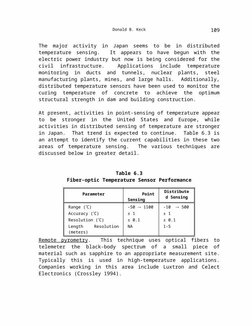
Table 6.3
104
Donald B. Keck
Fiber-optic Temperature Sensor Performance
Parameter Point Sensing Distributed Sensing
Range (°C) -50 ® 1100 -10 ® 500Accuracy (°C) ± 1 ± 1Resolution (°C) ± 0.1 ± 0.1Length Resolution (meters) NA 1-5
Remote pyrometry. This technique uses optical fibers to telemeter the black-body spectrum of a small piece of material such as sapphire to an appropriate measurement site. Typically this is used in high-temperature applications. Companies working in this area include Luxtron and Celect Electronics (Crossley 1994).
Fabry-Pérot (FP) interferometers. These temperature sensors measure the change in optical path length of a short piece of material whose thermal expansion coefficient and refractive index as a function of temperature are known. In some cases, multiple wavelengths are used to null out secondary effects such as strain or pressure in the material being measured. The FP is often made in materials such as glass, calcite, or zinc selenide (ZnSe), to name a few. Because of material choices in packaging, these sensors are limited to perhaps 400°C. Companies using this technique include Photonetics (formerly Metricor) and Sira, Ltd.
Fluorescence emission. Temperature is most often determined by measuring the fluorescence emission decay times from rare-earth-doped and transition-metal-doped phosphors. Neodymium-doped glass shows good performance over the range -50°C to 300°C (Fernicola and Crovini 1992). Chromium:LiSAF crystal has shown high sensitivity from 0°C to 100°C and is suitable for biomedical sensing (Zhang, Grattan, and Palmer 1992). Yttrium oxide and yttrium orthovanadate activated with europium (Eu) are suitable only for measurements in the 500°C to 1000°C range (Noel et al. 1992). Recently, Cr:YAG has been shown to operate over the range -25°C to 500°C. By using a digital signal processing scheme for the decay measurement, resolution of 0.1°C over the entire range is possible (Fernicola and Crovini 1994). Companies interested in this technique include Nortech Fibronics of Canada, whose products operate in the range -40°C to 250°C; Optrand, Inc., which sells devices for high-temperature engine control applications; and Takaoka Electric, which has taken over the activities of ASEA (Crossley 1994).
Distributed sensing. In the distributed temperature sensing area, Hitachi makes use of the thermal properties of Raman scattering in the material of a conventional optical fiber (see Hitachi site report in Appendix D). The company has a commercial product referred to as Fiber Optic Temperature Laser Radar (FTR). In this technique researchers use a large pulsed Nd:YAG laser (~100 watts) to excite Raman scattering, which is monitored using OTDR. Hitachi’s commercial unit will operate over the range -10°C to perhaps 500°C, depending on the fiber sheath material, with a quoted accuracy of ±1°C, and a resolution of ±0.1°C. The response time for this readout is between 15 and 90 seconds, depending on the unit. The longest length over which the OTDR technique has been successful is about
105
6. Optical Sensors and Specialty Fibers
30 km. Sumitomo Electric has reported that using a distributed Er-doped fiber, temperature distribution along this length has been measured, with ±2.3°C sensitivity and 6.5 m resolution (Wakami and Tanaka 1994).
Promising new optical sensor technologies. Although still in the research or development phase, several new activities show promise for improved capability. Using a Brillouin gain spectrum analysis, temperature and strain can be measured along the length of a fiber. Nippon Telephone and Telegraph (NTT) has demonstrated a technique using OTDR readout and finds a sensitivity of 1 MHz/°K (Shimizu, Horiguchi, and Koyamada 1994). Temperature and length resolution are better than 0.5°C and 60 meters, respectively. NTT has demonstrated this technique in two branches of a tree-and-branch network.
Building on the work in Er-doped fiber amplifiers for telecommunications, a high- temperature point sensor utilizing the green fluorescent intensity of Er-doped silica fiber has been demonstrated. This is based on the recently observed fast thermalization between the 4S3/2 and the 2H11/2 levels of Er. The relative population of these levels is represented well by a Boltzman distribution and thereby is related well to temperature. This technique was demonstrated between 300°K and 1000°K (Maurice et al. 1994). Researchers at China’s Zhejiang University Department of Physics are attempting to Cr-dope sapphire crystals to fabricate a “mini-black-body radiator” with a range of over 2000°C (Shen et al. 1994). They also report making Y-doped zirconia single-crystal fibers 300-500 mm in diameter and 100-250 mm in length. These should also be capable of operating at over 2000°C.
A very promising area, demonstrated by several groups, builds on the temperature-sensing capabilities of fiber Bragg grating (FBG) devices. A challenge is to fabricate a device that responds to just one measurand, that is, temperature; some progress has been made. At the Universities of Kent and Southhampton, two identical FBGs have been interferometrically monitored (Rao and Jackson 1994). By incorporating these in a bimetallic beam, temperature was reliably measured independent of other effects, with ±1% linearity achieved over the range 25°C to 65°C, and with a possible resolution of ±0.006 °C.
In related work, the reliability of the germanium-silica fibers in which the FBG are fabricated has been studied (Morey, Meltz, and Weiss 1994). The fibers seem to show creep above 650°C. Calculations suggest that germania diffusion at temperatures as high as 370°C is not a significant problem; however, due to this effect, the Bragg gratings could produce a shift of 1% in the measurand within 2.8 years at 650°C and within 100 hours at 800°C.
Strain sensors
Strain is measured by several methods, including fiber Bragg gratings, stimulated Brillouin scattering, and polarimetry in birefringent materials. Of these techniques, the FBG technology seems currently to be most preferred. In this technique a refractive index grating is written into a single-mode germanium-doped silica fiber. Strain is sensed by monitoring the
106
Donald B. Keck
reflected or transmitted wavelength from the grating as it is subjected to elongation. These gratings are easy to produce and should therefore be cost-effective. NRL and United Technology Research Center have had active programs in the area for several years. Using an interferometric readout for the reflected wavelength, NRL has recorded sensitivity of about 10-13 mstrain (A. Kersey, private communication with the author, February 1995).
Other laboratories working in this area include the Institute for Optical Research in Sweden, which has used a two-core fiber with FBGs to simultaneously measure both temperature and strain (Wosinski et al. 1994). Strain sensors based on FBG are also sensitive to temperature. Workers at the Department of Physical Sciences at Waterford Regional Technical College in Ireland and the Department of Physics at Herriott-Watt in Scotland have used dispersive Fourier transform spectroscopy to measure a set of parameters for both temperature and strain and extract the competing effects (Flavin, McBride, and Jones 1994). They measure 18 mstrain with their technique.
As noted above, two identical FBGs can be used to nullify temperature effects. Using these two FBGs in a strain sensor, as little as 9 mstrain was measured independent of temperature (Rao and Jackson 1994).
Using Brillouin OTDR as for temperature measurement, NTT has demonstrated sensitivity values of 5 MHz/0.01% strain. In two branches of a tree-and-branch network NTT has shown a length resolution of 60 meters and a strain resolution of about 50-100 mstrain.
Biomedical sensors
Development of fiber-optic sensors for medical applications began nearly 20 years ago. The proven success of biomedical optical sensors results from their reliability and biocompatibility and the simplicity of the sensor-physician interface. Both invasive and noninvasive types have been developed and manufactured. Nearly all of the activity in this sensor area is in the United States and Europe; few Japanese contributions are present in the published literature. For the most part, sensors are currently based on silica or plastic fibers that are coupled to sensitive sections called optrodes, and they utilize intensity modulation interrogation schemes. An emerging group of sensors is based on mid-IR (infrared) transmitting fibers. Many of these make use of spectroscopy in some fashion, either by using the directly transmitted or reflected light or by examining the fluorescent return from some material that acts as an extrinsic sensor. Many involve use of dual wavelengths to enhance sensitivity.
The following two activities are specific examples of spectroscopic biomedical sensors. Using the correct fluorophores on the ends of three fibers, pH, carbon dioxide, and oxygen can be simultaneously measured. Such a unit has been developed by CDI-3M Health Care, based on a system designed by Gehrich et al. (1986). CDI-3M has also developed a disposable probe for extracorporeal blood gas analysis (Baldini and Mignani 1994); it manufactures about 10,000 a month. Two other companies, Biomedical Sensors (UK) and Puritan Bennet Corporation (U.S.), make similar sensor heads. Oximetry in the blood is
107
6. Optical Sensors and Specialty Fibers
typically measured by exploiting the different absorption spectra of the hemoglobin and oxyhemoglobin in the near-IR (Baldini and Mignani 1994). Several invasive oximeters are commercially available from Oximetric in Mountain View, CA, and BTI in Boulder, CO.
Flow monitoring by laser Dopplerimetry is used in several biomedical sensing applications, including dermatology for testing of skin irritants, gastroenterology via endoscopes for making blood perfusion measurements in the stomach and duodenum, etc., and dentistry for contact probes to measure blood flow in the teeth and gums. Sensors are used in internal medicine for angiology and vascular surgery to monitor blood flow during vascular reconstruction and the degree of arteriosclerosis in arteries, and they are used in orthopedics for monitoring the blood perfusion in tissues during and after surgery. The most common types of probes rely on spectral monitoring of the backscattered light. Companies making probes of this type are Perimed in Sweden and Applied Laser Technology in the Netherlands (Baldini and Mignani 1994).
Gastroenterology in vivo monitoring is also being performed using spectroscopic techniques together with optical fiber light transport. In one technique, light from blue and green LEDs (light-emitting diodes) is transmitted through fibers to a small cavity between the fiber end and a retroreflector; any gastric fluids present are monitored by examining the relative spectral response. Prodotec (Italy) and Synectics (Sweden) have commercialized such a device (Baldini and Mignani 1994).
Fibers are used in a major ophthalmologic application: the detection of cataracts. By simply monitoring the backscattered light intensity from the lens of the eye, the onset of alpha-crystallite aggregation can be detected by autocorrelation measurements. The onset is delineated by a bimodal distribution of particle size in the backscattered radiation.
Short lengths of heavy-metal-doped fibers are used in monitoring radiation treatment for oncology patients. A simple differential attenuation measurement reliably reads dose level. Hyperthermia treatment of tumors relies on temperature monitoring during microwave or radio frequency irradiation. Luxtron (CA) developed one of the first such sensors based on the fluorescence spectrum of rare earth dopants in the fiber. Several other sensors based on Fabry-Pérot interferometer cavities and mid-IR pyrometry are being developed.
In the area of neurology, head trauma patients often require continuous monitoring of intracranial pressure; this is being done by fiber-optic catheters tipped with a small displacement diaphragm in front of two fibers. Simple monitoring of the retroreflected energy back into the second fiber measures diaphragm displacement and hence pressure. FP interferometers have also been used, as described below in the section on pressure sensors. A low-cost disposable probe is made by Camino Labs (CA) (Baldini and Mignani 1994).
Electrical and magnetic sensors
108
Donald B. Keck
Optical fiber sensors are an appealing choice for measurement of electric and magnetic fields and electrical current, because of their inherently dielectric nature. They provide galvanic isolation of the sensor head from ground potential, are less sensitive to electromagnetic interference, generally are of small size, and provide superior safety. Nearly all electric and magnetic field sensors based upon fiber optics are hybrid devices; that is, the fiber is attached to some other material and is used to monitor any changes in that material with electric and magnetic fields. This is required for electric fields since the intrinsic inversion symmetry of the glass matrix of the optical fiber precludes a Pockels effect; it is required for magnetic fields because the Verdet constant of telecommunication optical fibers is very small. Therefore, the fiber typically is used to sense dimensional changes of a piezoelectric or piezomagnetic material in the presence of electric and magnetic fields. Depending on the level of sensitivity required, the readout can be either by simple intensity measurement or by interferometric techniques. Because the fiber is sensitive to temperature, much of the present work is focused on removing that sensitivity.
In Sweden, the ABB Corporate Research Center has had ongoing field tests of interferometric current and voltage sensors that have been integrated into the gas-insulated high-voltage switch gear of a 220 kV station. For voltage sensing, the fiber is wound around quartz crystals and the resulting piezoelectric induced stress in the fiber is monitored with a white-light interferometer. Voltages from 0.1 to 1600 V are measured with errors well below 1% (Bohnert, Brandle, and Frosio 1994). The current sensor is based on using a modified fiber gyroscope readout to monitor the Faraday effect in an ultra-low birefringence fiber 100 meters in length. ABB reports a maximum detectable current of >23 kA, a sensitivity of about 2 A, and a relative error of ±0.15%.
Making use of the higher Verdet constants of SF57 glass, Siemens has demonstrated a current sensor based on measuring the rotation of the plane of polarization from traversing a reflecting ring of this material (Bosselmann and Menke 1994). Using a ring made of yttrium-iron-garnet (YIG), NIST scientists have built similar devices. The YIG has a Verdet constant of about 0.007 rad/A, compared to that of SF57 glass, which is about 0.00002 rad/turn. NIST has reported minimum detectable current of about 220 nA/ Hz (Rochford et al. 1994).
The same iron-garnet materials are used to sense magnetic fields. Using a 25 mm length of gallium-doped YIG together with flux concentrators, magnetic field sensitivity of about 1.4 pT/ Hz has been reported in a very simple polarization rotation experiment (Deeter et al. 1993). This is believed to be the most sensitive value observed.
The most sensitive voltage sensor reported is based upon an electrostrictive transducer made from lead-titanate-doped magnesium niobate with about 65 meters of fiber wrapped around it. The readout is accomplished interferometrically with the use of a dither frequency to remove noise. The interferometer is held at quadrature, and a phase-sensitive detection is used. Voltage sensitivity as low as 20 nV/ Hz has been reported (Fabiny, Vohra, and Bucholtz 1994).
109

6. Optical Sensors and Specialty Fibers
The Naval Research Laboratory has reported measurement of high magnetic fields by using an FBG. It was observed that the reflectance of the FBG as a function of wavelength was different for right and left circular polarizations. By interferometrically reading the phase difference due to FBG wavelength shifts, minimum detectable magnetic fields of about 2 gauss were possible. The dynamic range is very large, and fields of 100 Tesla (106 gauss) are measurable (Kersey and Marrone 1994).
Hoya Glass and Tokyo Electric Power Co., Inc., have collaborated on a fiber-optic current sensor. The single-mode fiber is made of a flint glass (high in lead) and therefore has a large (relative to telecommunication grade fiber) Verdet constant, but it also has relatively high transmission loss. Nevertheless, Hoya and Tokyo Electric Power are able to fabricate a 3-turn, 10 cm coil and obtain polarized transmission with good (~35 dB) extinction (Kurosawa et al. 1994). A superluminescent diode is used as the light source. Current is measured by observing the polarization rotation through crossed polarizers.
Matsushita Electric Industrial Company is building similar current sensors based upon thin garnet magneto-optic films inserted in a gapped toroid (Itoh et al. 1995). Unpolarized light from an 880 nm LED is transmitted to the sensor via a multimode fiber. In a new design, ball lenses are used to quasi-collimate the beam from the 80 mm diameter fiber and direct it through two polarizers and the thin garnet film. The film is a 50-mm-thick BiGdLaYFe garnet. A 200-mm-diameter fiber is used to collect the output beam. System loss is about 13 dB, and 1% linearity is achieved.
Matsushita is now selling an earlier version of this current sensor (~5% linearity) to one of the Japanese utility companies, Kansai Electric Power Company, for use as a current fault sensor (G. Day, private communication with the author, March 1995). The unit is located at “switching” stations between the substations and consumers, and it services about 100 customers. The expected lifetime of the device is 20 years. Even at present volumes, the price of the sensor head (transducer, optics, and fiber-optic links) is surprisingly low. The costliest component, which is roughly 25% of the cost of the device, is the polarizer (Corning Polarcor). In 1995, Matsushita began the third year of a seven-year agreement with Kansai, delivering about 1,000 units a year. Eventually, Matsushita envisions selling the 1%-linearity version in much higher volumes. Company managers see considerable competition in Japan from Sumitomo Electric, Toshiba, Mitsubishi, NGK Insulator, Furukawa Electric, Tokyo Electric Power, Fujikura, Hitachi, and Fuji Electric. At the present time, the ranges for electric and magnetic field sensors and current sensors are 0 to ±100 kV, 0 to 100 Tesla, and 0 to ± 25 kA, respectively. The highest sensitivities reported (see above) are 20 nV/ Hz , 1 pT/ Hz , and 200 nA/ Hz , respectively. More likely sensitivity values in commercial sensor units are thought to be 200 to 2000 nV/ Hz , and 10 to 100 pT/ Hz for electric and magnetic field sensors. For sensing very high electric and magnetic fields, Ezekiel et al. (1994) have demonstrated a two-photon technique for measuring Stark or Zeeman splittings of spectral lines using evanescent wave propagation in a fiber to probe a surrounding gas whose levels are split. If even
110
Donald B. Keck
higher fields are present, the hyperfine structure can be examined. This technique is being referred to as stimulated Raman gain spectroscopy (SRG).
Rotation sensors
Two types of optical rotation sensors have been developed over the past decade, both based on the Sagnac effect: the ring laser gyroscope and the fiber-optic gyroscope. When two light beams propagate in opposite directions around a common path, they experience a relative phase shift depending upon the rotation rate of the plane of the path. The actual heading or direction is obtained by integrating the output. In the case of the ring laser gyroscope (RLG), this phase change produces a change in the oscillation frequency of a laser that is integral to the path. In the case of the fiber-optic gyroscope, the phase difference is detected by interfering the two beams outside the path. According to Ryan, Hankin, and Kent (1992), the RLG, which is the first practical device to utilize the Sagnac effect, has now become a component of commercial inertial navigation systems (Honeywell has a contract for the Dornier 328). The FOG, however, being a simpler device, is currently receiving more attention due to its potential to achieve the required performance at a lower cost than with RLG or mechanical gyroscope technology.
The FOG consists of a loop of single-mode optical fiber (often polarization-maintaining fiber) and related coupler components, a semiconductor laser or superluminescent LED, and signal-processing electronics. The coupler components are generally fabricated in proton-exhanged LiNbO3 integrated-optic circuits. This material is chosen for its ability to modulate the light beam for improved detection.
The important metrics of FOG performance are minimum (sensitivity) and maximum rotation rates (degrees/sec.); bias drift, which is the variation in rotation rate with time due to ancillary effects such as temperature and aging; random walk, which is essentially a short-term noise in the system; and scale factor, which is the degree to which the measured rotation rate is independent of the absolute value of rotation rate. Other performance parameters include hysteresis, turn-on time, dynamic range, and spectral noise. Generally, three grades of product are identified, depending upon the values of these performance parameters: moderate, intermediate, and inertial grades. The moderate and intermediate categories of gyroscopes are being developed for industrial applications such as positioning systems, self-guided robots, and bore-hole survey systems. The inertial category is for navigation systems. Table 6.4 shows values of the important parameters for each grade.
Table 6.4Fiber-Optic Gyroscope Requirements, by Grade
Parameter Moderate Grade
Intermediate Grade
Inertial Grade
Max. Rate (deg/sec) 100 100 200
111
6. Optical Sensors and Specialty Fibers
Bias Stability (deg/hr) 10-100 0.1-1 0.01-0.0001Random Walk (deg/Öhr) 1-10 0.01-0.1 0.0001-0.001Scale Factor (ppm) 10000 100-1000 1-10
Many companies are active in FOG technology, at all stages of the innovation process, and for each performance grade. Typically it seems that U.S. companies are pursuing high-performance FOGs, while Japanese companies are aiming at the moderate and intermediate device performance. The high-performance work is driven by military applications and funding, while the moderate and intermediate work addresses commercial applications. Currently, U.S. companies such as Honeywell, Litton, Northrup, Allied Signal, Smith Industries, and Draper Laboratories can achieve FOG performance at the intermediate and navigational grade levels. Most of their programs are in the development stage. In Japan, Mitsubishi Precision and JAE have indicated they also have a research capability for achieving navigational grade performance. Photonetics S.A. in France also has commercially available FOGs with bias stability of a few tenths of a degree/hour and a dynamic range of ±2000 deg/s (LeFevre 1994).
For the lower performance grades, Hitachi Cable has a number of position and orientation products for use in autonomous vehicles, such as cleaning robots and unmanned dump trucks and carriers; radio-controlled helicopters for agricultural spraying; and devices for route surveying and mapping for pipes and tunnels and for underground construction. Fiber-optic devices are attractive in the latter uses because of their immunity to magnetic fields. Hitachi claims to be the largest producer of FOGs for both industrial and commercial applications. The JTEC panel’s hosts there indicated that the company is currently able to produce about 5,000 units/month (see also Hitachi Cable site report, Appendix D). In 1993, Hitachi won an R&D 100 Award for its FOG automotive navigation system, commercially deployed in certain Toyota models and used in conjunction with GPS (global positioning satellite) systems. Figure 6.6 shows the dashboard of a car equipped with one of the FOG units, as well as several other FOG applications.
New directions in the area of FOG rotation sensors include (1) obtaining better long-term stability to achieve the inertial grade performance requirements, and (2) reducing the overall cost of packaged devices. Some recent R&D aimed at higher performance makes use of telecommunications work with erbium-doped optical fiber amplifiers. This has been directed both toward making Er-doped fiber lasers and superfluorescent fiber sources (SFS) for FOG sources and toward employing the Er-doped fiber laser in a ring-laser configuration. An Er-doped ring fiber laser has been operated bidirectionally in multiple longitudinal modes with stable CW output. The ring laser produces a beat frequency proportional to the rotation rate. This work was conducted by the Department of Physics, KAIST, and the Korean Electronics and Telecommunication Research Institute (Kim, Kim, and Kim 1994). A fiber Brillouin ring laser using polarization-maintaining (PM) fiber has been demonstrated by Tanaka at the University of Tokyo (Tanaka and Hotate 1994). The
112
Donald B. Keck
rotation is measured by the beat frequency between the counter-propagating stimulated Brillouin scattering (SBS) beams. The PM fiber removes a source of noise due to mode-hopping between the two counter-propagating beams. Finally, Photonetics researchers indicate that using an Er-doped fiber source they expect to attain 0.01 deg/hour bias stability with 1 km coils in their FOG (LeFevre et al. 1994).
Fig. 6.6. Hitachi FOG for Toyota dashboard display (upper left), cleaning robot (lower left), and autonomous dump truck and helicopter applications (right). Describing the automotive application, an Hitachi brochure states, “The FOG detects rotation of cars...allowing you to know the direction in which you are headed....and travel to the desired destination in a minimum amount of time.” The Hitachi brochure also describes the important role such systems would play in intelligent vehicle highway systems.
Pressure sensors
Pressure sensors based on movable diaphragms, on small Fabry-Pérot interferometers, or on microbending, are the primary types being used today. They are finding use in biomedical, process control, marine, and engine control applications.
113
6. Optical Sensors and Specialty Fibers
The first pressure sensors for biomedical usage relied on piezoresistive techniques. These were developed in the late 1950s for intravascular pressure measurements. Later, fiber sensors based on moving diaphragms and monitoring retroreflected intensity emerged (Pahler and Roberts 1977). Camino Labs in San Diego, CA, manufactures devices of this type and is reported to be producing around 60,000 devices/year.
114