Embed Size (px)
Citation preview

113
CHAPTER 6
VECTOR CONTROL OF DOUBLY FED
INDUCTION GENERATORS
6.1 DESCRIPTION
One of the most recent rotor-side-control schemes is the doubly fed
induction generator. The method uses bi-directional AC-AC converters in the
rotor circuit to control the currents injected into the rotor. The converters,
being bi-directional, can be used to feed the rotor power back to the grid,
reducing rotor power losses and surmounting the main drawback of the rotor
resistance control.
Vector control techniques can be applied to control rotor currents to
achieve fast and decoupled control of the generator (Tapia et al 2003). This
chapter describes the control of doubly fed induction generators using vector
control principles and discusses the effectiveness of the control strategy in
controlling the output power in the presence of disturbances.
6.2 PRINCIPLE OF CONTROL
The control strategy involves the control of the rotor currents to
control the torque and speed of the induction generator, to achieve output
power control. Vector control also enables the decoupled control of stator flux
and electromagnetic torque (Darviersiang et al 2006).

114
Doubly fed control methodologies can generally be broken into two
categories: direct torque control and vector control. Direct torque control
(DTC) is a non-linear type of control that operates in a hysterisis manner. It
identifies the state of certain variables, such as flux and torque, and makes a
decision about what rotor voltage to apply to drive the state to a desired value.
A description of DTC for a cage induction machine can be found in
(Nakra et al 1988). The other form of doubly-fed control is vector control,
which is a linear control structure based on simple single input, single output
type controllers (Proportional Integration, for example) or more advanced
state space theory (Yazhou et al 2006). A rotating reference frame is used to
decompose complicated three-phase relationships to orthogonal components.
Vector control is used in this research.
6.3 PRINCIPLE OF OPERATION
The block diagram of the doubly fed generator, operating in the
super synchronous mode is shown in Figure 6.1 (Leonhard 1996 and Liexu
et al 2006). The stator is directly connected to the grid. The rotor is also
connected to the grid but by means of two back-to-back pulse width
modulation converters. The rotor side converter is current controlled to inject
the desired currents into the rotor (Fernando Valenciage 2007).
When the machine is operating in the generating mode, the
mechanical power Pm gets converted into electrical power in the stator (Pstator)
and in the rotor (Protor). The rotor power is processed by the PWM converters
and the grid side converter can be controlled to feed this power as both real
and reactive powers (Pr and Qr) (Rajib Datta et al, 2002). Thus, the induction
generator system is capable of generating a limited amount of reactive power,
unlike the pitch control or rotor resistance controlled wind energy systems.

115
The system can usually be made to operate at a unity power factor with a
± 10 % control range on the power factor for the entire system.
Figure 6.1 Structure of the doubly fed induction generator
6.4 DFIG STEADY STATE THEORY
An analytical method for the determination of the steady-state
control laws of the doubly fed induction generators (DFIG) used in wind
turbines is presented. The analytical model is used to derive the converter
control laws of the generator in terms of rotor voltage and control angle (real
and reactive power) overall operation speed range.
The DFIG design it needs suitable compromises between the wind
turbine performance and the respective characteristics of the DFIG, the
gearbox, the static converters and the associated control strategy. The optimal
solution in terms of performance and cost must be derived from global design
approach (Mustafa Kayikci et al 2008).
Pm
DC / AC
AC / DC
Protor
Grid
Pstator
Pr, Qr

116
Such an analytical formulation is also very efficient in terms of
execution time and robustness of the global optimization process. The
application of the proposed methodology is illustrated by the study of the
optimal reactive power allocation between the converters, which is an
important design challenge of DFIG system.
Most induction generators in the world are cage-type machines.
Special classes of induction generators with a three-phase wound rotor, called
doubly fed induction generators (DFIG), have become very popular for use as
wind generators as shown in Figure 6.2. These machines usually have a three-
phase inverter connected to the rotor windings, which allows direct control of
the rotor currents. Control of the rotor currents allows for variable speed and
reactive power control.
Figure 6.2 Doubly fed induction generator
A cage-type induction generator draws a fixed amount of reactive
power, which will cause the power factor to be lagging over all operating
conditions. In addition, a cage-type induction machine has a very small speed
range, typically only a few percent variations from the synchronous speed.
DFIG
AC DC
DC AC
DC link Rotor
Stator Grid

117
However, direct control of the rotor currents, as allowed by the
DFIG, allow for reactive power control and variable speed operation. A DFIG
can operate at lagging, unity, or leading power factor and can vary its speed
by a much larger margin (usually around 20 to 25 percent above or below the
synchronous speed).
These characteristics make the DFIG ideal for use as a wind
generator. Reactive power control allows a DFIG to help provide voltage
support for the grid, and variable speed operation allows the DFIG to operate
at a higher efficiency over a wide range of wind speeds.
6.4.1 DFIG Steady-State Analysis
The main component of the DFIG system and the conversion chain
is a wind turbine, a gearbox, a DFIG and a four-quadrant power converter.
The DFIG is usually designed with a low pair pole number (two or three) to
obtain acceptable performance in terms of reactive power consumption.
A gearbox is then necessary to adapt the low rotating speed of the wind
turbine (in a range of ~ 10-20 rpm for high-power wind turbines) to the
medium-rotating speed of the DFIG. The power converter is connected
between the grid and the DFIG rotor winding terminals by using slip rings.
The grid side converter (GSC) is usually controlled to operate at unity power
factor and to regulate the DC link voltage.
The rotor side converter (RSC) controls the electrical frequency in
the rotor windings and the real and reactive power flows. The rotor variable
frequency supply allows the variable rotating speed operation of the wind
turbine. Its rotating speed is imposed by the real power flow controlled by the
RSC that is used to provide a suitable torque control loop. The reactive power
managed by the RSC controls the power factor of the whole system, seen by
the grid (GPF) (Aguglia et al 2007).

118
6.4.2 The Influences of Model Simplification and Parameters
There has been a fast growing demand for the application of doubly
fed induction generators (DFIG) in wind power plants in recent years. They
have in particular dominated the market in last two years and within
modulation limits, are taken into account in all simulations.
With the envisaged demand and integration of wind power into the
power system, simulation studies and model validation become extremely
important. Currently, the doubly fed induction generator (DFIG) wind
turbines dominate the market due to cost-effective provision of variable-speed
operation. Their ability to control electrical torque and reactive power offer
superior performance concerning system stability. Adequate modeling of
these systems and clear understanding of the effects of different simplification
is paramount if reliable results simulations of power systems with high
penetration of DFIG-based wind plants are sought.
The DFIG mathematical models, as any other mathematical model
of physical device, are simplified either in order to save computational time or
to eliminate the requirement for hard to obtain data. They propose a method to
simplify aerodynamics to represent mechanical power. Modeling of the
aerodynamic efficiency, either Cp has been considered by numerical
approximations or through detailed aerodynamic models of the wind turbine;
however, this influence on transient operation of the DFIG has not been
illustrated (Mustafa Kayikci and Milanovic 2008).
Recently, there has been a growing interest in the use of wind
energy as environmental concerns are on the rise. In spite of this growth,
more technology advances are needed to make wind energy competitive with
many other energy supply methods. Simulation and modeling can be used to

119
study the performance of wind turbine systems (Roohollah Fadaeinedjad et al
2008).
6.4.3 Variable Speed Operation
The aerodynamic theory that justifies the benefit of the variable
speed operation is well described in a number of independent sources. In
short, the aerodynamics of the blades is such that for a particular wind speed,
there is a particular rotational speed that captures the largest amount of power
passing through the swept area.
2 31 2w wP r vπρ= (6.1)
Here ρ is the air density, r is the area radius (blade-length) and Vw
is the wind speed (all in SI units). Not all of this power can be captured by the
wind turbine. The theoretical limit set by Betz’s law (www.windpower.org),
states that the maximum amount of wind power Pw that can be captured by the
turbine is about 59 percent. This amount of available power captured by the
turbine is called the coefficient of power (Cp). The total power capture by the
turbine,
Pt = Pw × Cp
2 31 2t w pP r v Cπρ= (6.2)
Although the theoretical limit is 0.59, in practice most turbines
have a maximum Cp around 0.45. Cp is itself a complicated function of
aerodynamic factors, including the tip speed ratio, and the pitch angle of the
blades (β). To emphasize this, the coefficient of power can be written as Cp.
The tip speed ratio is the ratio of the linear velocity of the turbine blade tip to
the wind speed.

120
mech w=r /vλ ω (6.3)
(Please note that outside of this section, the symbol λ will be used for flux
linkages) In equation 6.3 is the rotational speed of the turbine blades.
A series of plots for Cp for different pitch angles is shown in
Figure 6.3. This figure and a very good discussion of this topic can be found
at the Matlab documentation website (www.mathworks.com).
Here it can be clearly seen that for a given pitch angle, there exists
a nominal tip speed ratio (λnom), that maximizes CP(λ, β) and hence maximizes
the power output of the turbine for a given wind speed. Therefore, it is highly
desirable to be able to change the speed of the turbine as the wind speed
changes, such that the turbine maintains the nominal tip speed ratio.
Figure 6.3 Coefficient of power as a function of tip speed ratio and
pitch angle
121
For any induction machine, cage or doubly fed type, the steady
state frequency of the rotor currents and voltages will be the slip frequency.
Therefore
mech syn slip syn r2 fω ω ω ω π= − = − (6.4)
In equation (6.4), ωmech is the rotor rotational speed ωsyn is the
synchronous speed and fr is the electrical frequency of the rotor currents and
voltages (all in electrical rad/sec). Here it can be clearly seen that, since the
synchronous speed is fixed by the grid, the rotational speed can be controlled
directly by using the rotor side inverter in Figure 6.2 to force the rotor
currents to a desired frequency.
In practice, the rotational speed of the machine is controlled via
speed and torque control loop cascade structure.
6.4.4 Active and Reactive Power Control
The supervisory control at Wind farm side, to be capable of
providing generating margin from a wind farm, it should be able to receive
operator’s request and distribute power reference signal to each machine for
the desired generation. Further, calculates each machine’s deloaded condition,
come up with a desired generating margin and can be realized by the control
scheme (Michal et al 2006).
Active Power Control of a DFIG, the active power control of a
DFIG is a series of regulating processes between wind turbine and induction
generator. When wind velocity is high enough, the turbine controller regulates
the pitch angle of the turbine blade to ensure the adequate torque for the given
wind power (Le-Ren Chang-Chien et al 2008).

122
Another significant advantage of the DFIG is the real and reactive
power control. Note that real power is directly related to the torque and speed
of the generator, so in many ways the issue of real power has already been
addressed in the previous section, although the material presented in this
section offers a different perspective.
A per phase equivalent circuit for a doubly fed induction machine is
shown in Figure 6.4 (Rongve et al 2003 and Riaz 1959). Variables with the
notation denote rotor quantities as seen from the stator side.
Is Ir’
+ Im
Vs
-
Figure 6.4 DFIG per phase equivalent circuit
Some informative relations of a general nature can be seen by
simplifying and neglecting the effects of Rs, jXls and jXlr’. In this case, the per
phase stator and rotor power can be expressed as
*s s s s sS =P +jQ =V I (6.5)
*r r r r rS =P +jQ =V I (6.6)
Assuming a unity turns ratio between the stator and rotor:
V’r = Vr and I’r = -Ir.
+ -
Rs jXls jX’lr
jXm
'rR
s
'rVs
123
Then power equations can be written for Figure 6.4. (Note: if there
is a non-unity turns ratio between the stator and rotor, it will not affect the
power equations. Therefore, this analysis is valid for any turns ratio)
2 2* ' ' ' '*
s s r r s m r rV I = I R s + j V X + V I s (6.7)
The active and reactive power is found by taking the real and
imaginary parts of (6.7)
2 2' ' * ' '
r r r rI R s Re I R ss r r rP V I s P s⎡ ⎤= − = −⎣ ⎦ (6.8)
[ ]2 2s m s mV X Im V Xs r r rQ V I s Q s= − = − (6.9)
Since the slips are small, (6.8) and (6.9) illustrate that a small
amount of rotor power yields a large amount of stator power. Therefore, the
DFIG has the effect of amplifying the rotor inverter power. The desired speed
range of the generator is directly related to the power rating of the inverter.
For example, for a DFIG with a plus / minus speed range of 20 percent
(0.2 > s > -0.2), the rotor inverter must be rated for around 20 percent of the
generator rating.
This analysis highlights two of the DFIG’s main advantages. First,
a small amount of reactive power from the rotor becomes a large amount of
reactive power in the stator. Second, the rotor power rating is required to be
only a fraction of the entire generator rating.
A DFIG is a special type of induction generator with a wound rotor.
By proper control of the rotor converter, a DFIG’s can achieve reactive power
control and a wider speed range than for a cage-type induction generator.
Variable speed operation allows the DFIG to capture a greater amount of
power in the wind for a given wind speed.

124
There are three main advantages of a DFIG. First, variable speed
operation. Second, a small amount of rotor reactive power becomes a large
amount of stator reactive power. Third, the rotor converter only needs to be
rated for a fraction of the total generator rating.
6.5 dq ANALYSIS FUNDAMENTALS
The time domain voltage, current, and flux linkages equations for a
doubly fed machine are quite complicated. There are three stator windings
and three rotor windings, all linking each other. In particular, the interaction
between the stator and rotor windings is complicated by the linkage being
dependent on the angular position of the rotor. The flux linkage matrix is a
6 × 6 matrix with a dependence on rotor position (Bolik 2004). As an
example, the upper case (example abc) denotes the stator and lower case
(example ABC) denotes the rotor.
( )a a s a mechV i R d dtλ θ= + (6.10)
( ) ( ) ( ) ( )a mech aa ab ac aA mech aB mech aC mechλ θ λ λ λ λ θ λ θ λ θ= + + + + + (6.11)
The symbol λ is used for flux linkage. It is not related to the tip
speed ratio (λ = r ωmech/vw). There are five more sets of equations for the
remainder of the stator and rotor windings.
The flux linkage equation (6.11) is unwieldy in that it has many
terms, half of which have a dependency on the rotor position. The analysis
can be simplified greatly by transforming the three-phase stator and three-
phase rotor (with the rotor angular displacement between them) to a fictional
two-phase stator and two-phase rotor (with no angular displacement), as
shown in Figure 6.5(a) and (b). These two-phase windings are then allowed to
rotate at an arbitrary speed. Often, it is most advantageous to allow the

125
fictional windings to rotate at the synchronous speed. In such a case, the
winding currents will be DC in steady state. There are two ways of creating a
rotating flux: AC currents with fixed windings or DC currents with rotating
windings). These fictional two-phase windings are called d-and q-windings.
(a) (b)
Figure 6.5 (a) Three phase rotor and three phase stator with angular
displacement, (b) Two- phase d and q windings with rotor
and stator aligned
The d and q-axes can be physically considered to be rotatable
orthogonal windings that will produce the same space vector as the fixed
three-phase a, b, and c-windings.
The space vector is a spatially oriented, complex plane
representation of a three-phase quantity.
120 240( ) ( ) ( )j js a b ci i t i t e i t e= + + (6.12)
Equation (6.12) is a space vector representing the cumulative,
effective current of the three instantaneous phase currents. In this way, a
space vector represents a single, rotatable winding that produces the same
effect as the three fixed windings.

126
Taking this a step further, the real and imaginary parts of the space
vector can be thought of as the current in two stationary orthogonal windings
that produce the space vector. These fictional two-phase fixed windings are
sometimes referred to as “alpha” and “beta” windings. If these windings are
unstuck from their stationary positions, and allowed to rotate or orientate
themselves as the control designer sees fit, they can be called d- and
q-windings.
The d-axis and q-axis stator currents are the (scaled) reflection of
the space vector on the d-axis and q-axis. In Figure 6.6, the scaling factor
is 2 3 , the so-called “power invariant” transformation, because with this
scaling factor a a b b c c sd sd sq sqV i V i V i V i V i+ + = + .
The stator and rotor a-phase, b-phase and c-phase voltage equations
and flux linkage equations can be transformed to the d-axis and q-axis, where
they are much simpler.
Figure 6.6 Space vector reflections on to d – axis and q – axis

127
sd sd s sd d sqV i R d dtλ ω λ= + − (6.13)
sq sq s sq d sdV i R d dtλ ω λ= + + (6.14)
rd rd r rd dA rqV i R d dtλ ω λ= + − (6.15)
rq rq r rq dA rdV i R d dtλ ω λ= + + (6.16)
The flux linkage equations are also easily defined, as in
equation (6.17) through (6.20).
( )sd
s
is m sd m rd
i
L L i L iλ = + +14243
(6.17)
( )sq
s
is m rd m rq
i
L L i L iλ = + +14243
(6.18)
( )rd
r
ir m rd m sd
i
L L i L iλ = + +14243
(6.19)
( )rq
r
ir m rq m sq
i
L L i L iλ = + +14243
(6.20)
The most important decision made by the designer implementing
the dq transform is the choice of θ. It is chosen arbitrarily, although some
choices make more sense than others do.
6.5.1 dq Analysis for Non-Unity Turn’s Ratio
For this research and in most practical work, the DFIG will have a
non-unity turns ratio, n. Therefore, the flux linkage equations must include the
turn’s ratio. Also, it will be useful to define the d- and q-axis magnetizing
current.

128
md sd rdi i ni= + (6.21)
mq sq rqi i ni= + (6.22)
Including magnetizing current and the turn’s ratio, the flux linkage
equations can be written as:
( )sd
s
is m sd m rd is sd m md
i
L L i nL i L i L iλ = + + = +14243
(6.23)
( )sq
s
is m sq m rq is sq m mq
i
L L i nL i L i L iλ = + + = +14243
(6.24)
( )2rd
r
ir m rd m sd ir rd m md
i
L n L i nL i L i nL iλ = + + = +14243
(6.25)
( )2rq
r
ir m rq m sq ir rq m mq
i
L n L i nL i L i nL iλ = + + = +14243
(6.26)
Only Lm can be considered to be “referred” to the stator. All other
variables are as seen from their respective terminals. For example, Llr is the
rotor leakage inductance as would be measured from the rotor terminal and Irq
is the actual rotor current.
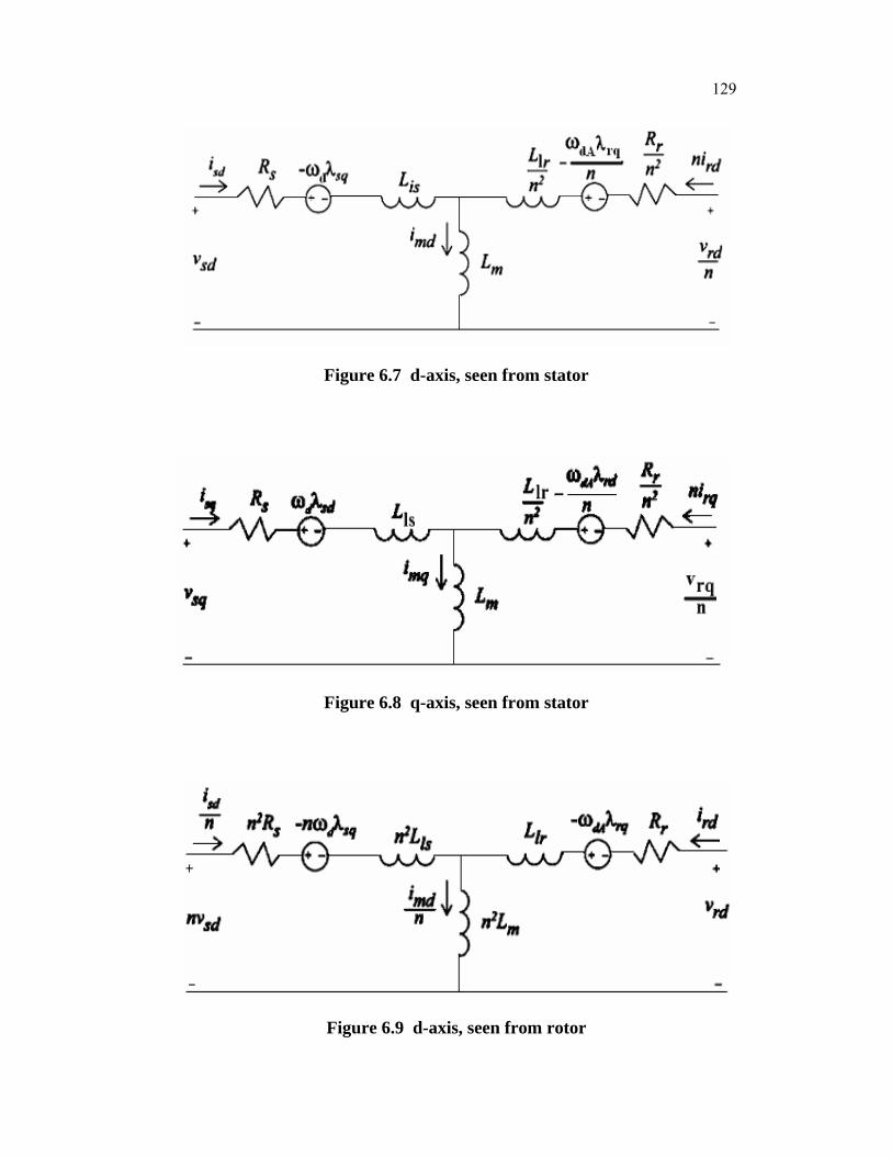
Substituting equation (6.23) through equation (6.26) in the voltage
equation (6.13) through equation (6.16), the resulting equation can be
represented in circuit form, as shown in Figures 6.7, 6.8, 6.9 and 6.10.
129
Figure 6.7 d-axis, seen from stator
Figure 6.8 q-axis, seen from stator
Figure 6.9 d-axis, seen from rotor

130
Figure 6.10 q-axis, seen from rotor
6.5.2 DFIG Current and Voltage dq Transformer Functions
The standard strategy for DFIG control is to use the rotor d and q-
axis voltage, vrd and vrq, to control the rotor currents, ird and irq. In order to
design the controllers and to gain an understanding of how any of the voltages
affect any of the currents, it is necessary to derive the DFIG current and
voltage transfer functions.
This can be done by substituting equation (6.23) through
equation (6.26) into equation (6.13) through equation (6.16) and rearranging
to get a state equation matrix with currents as the state variables and voltage
as the inputs, resulting in equation (6.27).
[ ] [ ]( , ) ( , )
sd sd sd
sq sq sqd dA d dA
rd rd rd
rq rq rq
i i Vi i Vd A Bi i Vdti i V
ω ω ω ω
⎡ ⎤ ⎡ ⎤ ⎡ ⎤⎢ ⎥ ⎢ ⎥ ⎢ ⎥⎢ ⎥ ⎢ ⎥ ⎢ ⎥= +⎢ ⎥ ⎢ ⎥ ⎢ ⎥⎢ ⎥ ⎢ ⎥ ⎢ ⎥⎢ ⎥ ⎢ ⎥ ⎢ ⎥⎣ ⎦ ⎣ ⎦ ⎣ ⎦
(6.27)
The A (ωd, ωdA) and B (ωd, ωdA) matrices are dependent on ωd on
ωdA. The dq frame speed, can assumed to be constant. The relative speed of
the dq frame to the rotor contains some mechanical dynamics because it is

131
dependent on the rotor speed. However, for the purposes of linearization and
converter control design, the electrical dynamics can be considered much
faster than the mechanical dynamics, and ωdA can be considered constant.
6.6 VECTOR CONTROL
In the stator flux reference frame, simplified equations describing
the dynamics of the induction machine are (Peter Vas 1998)
r r r rs s s s k sV R i d dt jλ ω λ= + + (6.28)
where ωk is the angular speed of the stator flux reference frame. The rotor
voltage equations are not necessary, as the rotor side is current controlled and
the rotor current space vector rir is known.
The stator flux reference frame refers to a reference frame whose
d-axis is aligned along the stator flux space vector. So, by definition,
; 0rs ds qsλ λ λ= = (6.29)
Substituting equation (6.29) into equation (6.28) and separating into
d and q components (Seigfried Heir 2006),
ds s ds sV R i d dtλ= + (6.30)
qs s qs k kV R i ω λ= + (6.31)
since
r r rs s s m rL i L iλ = + (6.32)

132
The d and q components of the stator current can be expressed in
terms of the stator flux and the rotor current as
( )qs m s qri L L i= − (6.33)
ds s m dr si L i Lλ= − (6.34)
Substituting equation (6.34) into equation (6.30)
( )k qs s m qr s sV R L i Lω λ= + (6.35)
Substituting equation (6.16) in equation (6.13),
( )s sds s m dr
s
d RV L idt Lλ λ= − − (6.36)
Equation (6.36) expresses the induction machine dynamics in terms
of the input quantities and can be solved to obtain the stator flux linkage
variation. Equation (6.35) is an expression to compute the angular velocity of
the stator flux reference frame, which is used in the conversion from abc to dq
quantities. Since λqs = 0, the electromagnetic torque produced by the machine
can be expressed as
e s qrr
LmT iL
λ= − (6.37)
Thus the stator flux can be controlled by the d- component of the
rotor current and the torque produced can be controlled by the q-component
of the rotor current (Seagay 2005). To enable the control of the flux and the
torque, a stator flux estimate is required, which can compute the torque
produced by the induction generator and estimate rotational speed of the

133
stator flux reference frame, using the stator voltages, rotor currents and the
rotor speed as input. The estimator is based on equation (6.28) through
equation (6.37) and the SIMULINK implementation of the estimator is shown
in Figure 6.11 (Rabira and Culloch 2000).
Figure 6.11 Stator flux estimator
6.6.1 Output Power Controller Design
The block diagram of the controller used in the doubly fed
induction generator system is shown in Figure 6.12 (Dalta and Ranganathan
2002). The flux controller, which is shown in Figure 6.12(a), generates the
d-component of the rotor current reference, which is used by the inverter to
control the currents injected into the rotor. Similarly, the speed controller is
used to generate the q-component of the rotor current reference, as shown in
Figure 6.12(b).

134
Figure 6.12(a) Flux controller for the doubly fed generator
Figure 6.12(b) Speed controller for the doubly fed generator
The speed reference is generated using the information about the
desired power output and the wind velocity. The speed reference generator is
shown in Figure 6.13. The speed reference generator has two paths, a non-
linear feed forward path and a linear feedback path as in the case of the pitch
control system. The feed forward path computes the power coefficient
required to capture the desired power using,
31
2
refp
w
PC
Avρ= (6.38)
The tip speed ratio is then obtained from a lookup table. The
feedback path compensates for any losses in the system.

135
Figure 6.13 Reference speed generator
The following are the values used for the gains of the P-I
controllers in the simulation.
For the flux controller:
Kp = 10 and Ki = 50.
For the torque controller:
KP = 10 and Ki = 50.
For the speed controller:
Kp = 5 and Ki = 25.
For the power controller:
Kp = 0 and Ki = 1.
The SIMULINK implementation of the system is shown in
Appendix A5.
6.7 RESULTS OF THE SIMULATION
The power output of the system for the wind speed variation is
shown in Figure 6.14. The output power variation is about 2 % and the
settling time is about 5 secs. The system response is fast and the output power
variation is minimal compared to pitch control and rotor resistance control
(Roohollah Fadainedjad et al 2008).

136
Figure 6.14 Output power variation for the DFIG
The rotor speed of the generator is plotted in Figure 6.15. The rotor
speed is also within the limits (10 % of the rated). The rotor power can be fed
back to the grid, thus minimizing losses in the system. Thus, based on our
discussion, comparison between the fixed speed and the variable speed wind
turbines is detailed in Table 6.1.
Figure 6.15 Rotor speed of the induction generator

137
Table 6.1 Comparison between various wind turbine systems
Fixed speed Variable speed wind turbine
Squirrel Cage Induction Generator
Synchronous generator Doubly fed induction generator
No Power Electronics Required
Power Electronics required. (100% rating of generator)
Power Electronics required (10 – 40 % rating of machine)
Reactive power support required
Ability to generate reactive power and supply to grid
Ability to generate reactive power and supply to grid
Voltage control not possible
Voltage control possible Voltage control possible
Control of power not possible
Control of active power possible
Control of active power possible
Stall or Active stall control installed
Pitch angle control installed
Pitch angle control installed
Higher vibrations and mechanical stress
Low vibrations and mechanical stress
Low vibrations and mechanical stress
Variations in the wind power are reflected into grid
Wind turbine acts as inertia
Wind turbine acts as inertia
Thus, from Table 6.1, we can see that variable speed wind turbine
with DFIG has several advantages as compared to other types.
6.8 SUMMARY
Vector control is the use of a two-phase transformation to break a
system down into orthogonal components for easier control. For three-phase
machines, this can be seen as the transformation of three-phase real quantities

138
to complex rotating quantities in a fixed frame (space vectors) and then
transformed as orthogonal components in a rotating frame (the d-axis and q-
axis). The d-axis and q-axis, while a fictional mathematical abstraction, can
be thought of in a physical sense as actual rotating windings. This allows an
equivalent, simpler representation of a three-phase machine as a two-phase
machine. Control and analysis can be done more easily, intuitively in degree
frame.
The doubly fed induction generator is found to have the least output
power variation and the fastest response of the three control techniques
simulated. Moreover, the additional complexity of the system enables an
overall system power factor control, to help operate the system at close to
unity power factor.