Embed Size (px)
Citation preview
Chapter 6 Mars Reconnaissance Orbiter
Jim Taylor Dennis K Lee and Shervin Shambayati
61 Mission Overview The Mars Reconnaissance Orbiter (MRO) [1 2] has a suite of instruments making observations at Mars and it provides data-relay services for Mars landers and rovers MRO was launched on August 12 2005 The orbiter successfully went into orbit around Mars on March 10 2006 and began reducing its orbit altitude and circularizing the orbit in preparation for the science mission The orbit changing was accomplished through a process called aerobraking in preparation for the ldquoscience missionrdquo starting in November 2006 followed by the ldquorelay missionrdquo starting in November 2008 MRO participated in the Mars Science Laboratory touchdown and surface mission that began in August 2012 (Chapter 7)
MRO communications has operated in three different frequency bands
1) Most telecom in both directions has been with the Deep Space Network (DSN) at X-band (~8 GHz) and this band will continue to provide operational commanding telemetry transmission and radiometric tracking
2) During cruise the functional characteristics of a separate Ka-band (~32 GHz) downlink system were verified in preparation for an operational demonstration during orbit operations After a Ka-band hardware anomaly in cruise the project has elected not to initiate the originally planned operational demonstration (with yet-to-beshyused redundant Ka-band hardware)
201
202 Chapter 6
3) A new-generation ultra-high frequency (UHF) (~400 MHz) system was verified with the Mars Exploration Rovers in preparation for the successful relay communications with the Phoenix lander in 2008 and the later Mars Science Laboratory relay operations
Lockheed Martin Space Systems Denver Colorado is the prime contractor for MRO They built the spacecraft and have provided flight operations support during the mission The Jet Propulsion Laboratory (JPL) Pasadena California manages the project for the National Aeronautics and Space Administration (NASA) Washington DC The Flight Team is located at both Lockheed and the Jet Propulsion Laboratory Refer to the Mars Reconnaissance Orbiter home page [1 2] for current MRO information
62 Mission Phases and Orbit Summary
621 Mission Objectives The Mars Reconnaissance Orbiter (MRO) mission has the primary objective of placing a science orbiter into a low and near-circular Sun-synchronous Mars orbit to perform remote sensing investigations to characterize the surface subsurface and atmosphere of the planet and to identify potential landing sites for future missions The MRO payload conducts observations in many parts of the electromagnetic spectrum including ultraviolet and visible imaging visible to near-infrared imaging spectrometry thermal infrared atmospheric profiling and radar subsurface sounding at spatial resolutions substantially better than any preceding Mars orbiter
The driving theme of the Mars Exploration Program (MEP) is to understand the role of water on Mars and its implications for possible past or current biological activity The MRO is studying the history of water on Mars Another Mars mission the Mars Exploration Rover (MER) has shown that water flowed across the surface in Marsrsquo history The MRO is searching for evidence for when the water was on the surface and where it is now and any indicators of whether water persisted on the surface of Mars long enough to provide a habitat for life
In terms of telecommunications (telecom) the MRO mission
Provides X-band (~8 GHz) uplink (command) downlink (telemetry) and navigation (two-way Doppler turnaround ranging and differential one-way ranging) with the Deep Space Network (DSN) The directshyfrom-Earth (DTE) uplink can also carry data intended for relay to a surface vehicle and the DTE downlink can also carry data relayed to MRO from a surface vehicle
203 Mars Reconnaissance Orbiter
Provides ultra-high-frequency (UHF) data relay and navigation support services to landing MEP missions during their entry descent and landing (EDL) phase and subsequently provide UHF two-way relay and navigation services to landed surface vehicles or to other orbiting spacecraft for example a sample-return canister waiting for pickup and return to Earth
Perform an operational demonstration of high-data-rate Ka-band (~32 GHz) downlink telecommunications and navigation services (using the X-band uplink) with the DSN
622 The MRO Spacecraft The MRO uses a new spacecraft bus design provided by Lockheed Martin Space Systems Company Space Exploration Systems Division in Denver Colorado
The X-band antennas for communication with the DSN are at the top in Fig 6-1 Of the two low-gain antennas (LGAs) that are fixed-mounted to the high-gain antenna (HGA) LGA1 is called forward-facing because it is pointed in the same general direction as the gimbaled HGA The other LGA LGA2 points generally in the opposite direction The UHF antenna that is used for communicating with surface vehicles is aligned with the +z axis which is also the science instrument boresight Throughout the science and relay operations phase this axis is usually oriented vertical toward Mars
The orbiter payload consists of six science instruments and three new engineering payload elements listed as follows
Science instruments
o HiRISE High Resolution Imaging Science Experiment o CRISM Compact Reconnaissance Imaging Spectrometer for Mars o MCS Mars Climate Sounder o MARCI Mars Color Imager o CTX Context Camera o SHARAD Shallow (Subsurface) Radar
New engineering payloads
o Electra UHF communications and navigation package o Optical Navigation Camera Experiment (ONC) o Ka-band Telecommunications Experiment
Figure 6-1 is a sketch showing the major externally visible parts of the spacecraft
204 Chapter 6
High Gain Antenna
HiRISE
CTX
+y
+z+x
+y
+z+x
Low Gain Antennas (2) HGA Gimbals
MCS
TWTA Panel
CRISM
Solar Array
UHF Antenna
Fig 6-1 Sketch of the MRO spacecraft with coordinate directions
623 Mission Phases In order of occurrence the six phases of the MRO primary mission are launch cruise approach and orbit insertion aerobraking primary science and relay [3] The following paragraphs provide overviews of the spacecraft activities in each phase Specific telecom calibrations and activities are described in subsequent sections
6231 Launch The spacecraft was launched on August 12 2005 Approximately 58 minutes after launch the spacecraft separated from the launch vehicle About 4 minutes prior to separation the X-band traveling-wave tube amplifier (TWTA) began warm-up and the spacecraft began transmitting a downlink through the forward-facing low-gain antenna (LGA1) about 1 minute after separation MRO remained in a single inertial attitude throughout the launch period By 14 minutes after separation the craftrsquos solar panels finished unfolding About 21 minutes after separation in order to avoid interfering with solar array deployment the HGA was deployed from the stow position
The spacecraft established radio contact with Earth 61 minutes after launch and within 4 minutes of separation from the upper stage Initial downlink-only contact came through an antenna at the Japan Aerospace Exploration Agencyrsquos Uchinoura Space Center in southern Japan
When MRO came into view at the Goldstone California DSN site a 34-m station established an X-band uplink with the MRO receiver The uplink carrier
205 Mars Reconnaissance Orbiter
provided a reference for two-way Doppler and turnaround ranging on the downlink as well as establishing commandability
The ultra-stable oscillator (USO) in the telecom subsystem was turned on within hours after launch so that the one-way downlink frequency would be stable prior to cruise phase activities The USO has operated continuously except for a few hours during safe mode in January 2006
6232 Cruise The cruise phase began about 3 days after launch and ended 60 days prior to Mars orbit insertion (MOI) The duration of the cruise phase was approximately 150 days
Early cruise included an in-flight UHF antenna gain pattern measurement in conjunction with the 150-foot (46-m) diameter ldquoStanford Dishrdquo radio telescope [23] The receive and transmit gain measurements were made at the 400-MHz relay operations frequencies with the nadir deck (instrument and UHF boresight) pointed back toward the Earth1
The Type-I interplanetary trajectories for MRO did not have transfer-angle constraints or other singularities and so the trajectory correction maneuver (TCM) timing was based primarily on operational considerations and standard practice [22] TCM-1 included firing the six main (170-newton N) thrusters for 15 seconds on August 27 2005 This engine burn followed a 30-second burn of six smaller (22 N) thrusters which settled propellant in the craftrsquos fuel tank for smoother flow With communications on the LGA MROrsquos orientation was adjusted prior to the burns to point the engines in the proper direction for the maneuver and the spacecraft returned to cruise-phase attitude after the trajectory adjustment Besides putting MRO on course for the Mars target point TCM-1 checked out the engines that would be required for MOI
Instrument payload calibrations began on August 30 The higher-resolution cameras were pointed at the Earth and the Moon as the spacecraft continued its flight to Mars
1 Pre-launch measurements could not be nearly so accurate because the spacecraft was not in its final flight configuration and because of antenna interactions outside the spacecraft At 400 MHz any electromagnetic conducting surfaces on the spacecraft parasitically couple with the UHF LGA forming a composite antenna pattern This parasitic coupling would also occur on the ground with any metallic test equipment surrounding the spacecraft The Stanford Dish test was a ldquofirstrdquo in terms of an in-flight measurement of this type
206 Chapter 6
TCM-2 on November 18 2005 used only the smaller TCM thrusters in a 20-second burn Two other TCMs built into the mission plan [3] were not required
6233 Approach and Mars Orbit Insertion Following the interplanetary cruise and Mars approach phases of the mission the MRO achieved MOI on March 10 2006 The MOI burn fired the craftrsquos main thrusters for about 27 minutes to reduce velocity by about 20 percent as the spacecraft swung around Mars at about 5 kilometers per second (kms) or about 11000 miles per hour (mph)
The initial post-MOI orbit started from the MOI aim point of 360 km above the Martian surface approaching from the south As an example of how flight dynamics in the form of trajectory design works Mars actually caught up to the slower moving MRO spacecraft at this point After launch MRO spiraled out from Earth to Mars and Mars caught MRO from behind as the MRO radial motion around the Sun was slower than the motion of Mars at time of MOI
After MOI and before the aerobraking phase began the orbiter flew about 426 km (265 miles) above Marsrsquo surface at the nearest point (periapsis) of each orbit then swung out more than 43000 km (27000 miles) to the most distant point (apoapsis) before heading in again The initial orbit period was about 35 hours
After MOI while preparing for aerobraking the flight team tested several instruments obtaining the orbiterrsquos first Mars pictures and demonstrating the ability of its Mars Climate Sounder instrument to track the atmospherersquos dust water vapor and temperatures
6234 Aerobraking In aerobraking the trajectory design deliberately causes the spacecraft to pass through the upper reaches of the Mars atmosphere on each periapsis pass The atmospheric friction acts as a velocity brake and each such pass lowers the apoapsis altitude at the other end of the orbit After the correct apoapsis altitude is attained the aerobraking phase is ended with a periapsis raise maneuver performed to bring periapsis out of the atmosphere Aerobraking is made more complicated because the Martian atmospheric density as a function of altitude and latitude also varies with time Infrared-sensing instruments and cameras on two earlier Mars orbiters (Mars Global Surveyor through late 2006 and Odyssey continuing as of 2010) were the main sources of information to the advisory team of atmospheric scientists providing day-to-day data about variations in Marsrsquo atmosphere as the aerobraking campaign continued In addition the Mars Climate Sounder instrument on
207 Mars Reconnaissance Orbiter
MRO itself provided data to monitor changes in temperature that affected the atmospherersquos thickness
Aerobraking began on March 30 2006 and ended August 30 2006 An initial propulsive maneuver firing of the 22-newton (N) thrusters for 58 seconds at apoapsis put the MRO spacecraft into an active aerobraking orbit That apoapsis maneuver lowered the periapsis altitude to 333 km (207 miles) The aerobraking phase required 445 orbits of carefully calculated dips into Marsrsquo atmosphere Aerobraking and a phasing maneuver on September 5 shrank its orbit from the post-MOI elongated ellipse to a more nearly circular orbit
Aerobraking ended with MRO in a slightly elliptical low-altitude Sun-synchronous orbit called the science orbit After a successful final circularization propulsive periapsis-raise maneuver on September 11 2006 the science orbit has a period of 1 hour and 52 minutes with an apoapsis of 316 km over the North Pole and a periapsis of 250 km over the South Pole [1 2]
Solar Conjunction Between the end of aerobraking (with the primary science orbit established) and the start of the primary science mission phase was a solar conjunction Defined as the time period when the SunndashEarthndashMars angle is 5 degrees (deg) or less this first solar conjunction was from October 7 to November 8 2006 The Ka-band communications demonstration was planned to conduct activities during conjunction to monitor and compare simultaneous X- and Ka-band telemetry downlinks The DSN supported one 8-hr pass per day to a 34-m antenna during this period
Solar conjunctions of Mars have a periodicity of about 26 months and the EarthndashMars range is very nearly at maximum when the SunndashEarthndashMars angle is minimal at conjunction The SunndashEarthndashMars geometry at conjunction causes several communications challenges As the SunndashEarthndashMars angle decreases below about 5 deg the communications signal passes through an increasing amount of solar plasma which causes non-linear scintillation on the signal In addition the background noise from the Sun itself reduces the received signal-to-noise ratio (SNR) at the DSN Finally the Sun itself subtends 105 deg in the sky as viewed from Earth and can completely block the line-of-site signal path to the MRO spacecraft if the SunndashEarthndashMars angle falls below 025 deg Because conjunction is established by MarsndashEarthndashSun geometry all orbiters and landers at Mars have the same conjunctions Table 6-1 gives the dates of Mars solar conjunction for 2004 through 2021 Proximity communications with surface vehicles would not be directly affected
208 Chapter 6
Table 6-1 Mars solar conjunction dates and minimum SEP angles (2004ndash2021)
Date of Minimum SEP
SEP Angle
Date of Minimum
SEP Angle
Date of Minimum
SEP Angle
Angle (deg) SEP Angle (deg) SEP Angle (deg)
09152004 096 02042011 108 07272017 110
10232006 039 04182013 040 09022019 108
12052008 046 06142015 062 10082021 065
Data received from Ref 4 and personal communication from David Morabito 12082010
6235 Primary Science Mission During the science phase MRO examined parts of the planet in detail and monitored the entire planet daily throughout a full cycle of Martian seasons or 669 sols for one Mars year The duration of this phase was about two Earth years (November 2006 to November 2008 starting with the end of aerobraking The science experiments consisted of global mapping of Marsrsquo surface regional surveys for potential future Mars landing sites targeted observations of areas of interest and mapping of the Mars gravity field The primary science mission ended with the onset of solar conjunction2 Figure 6-2 shows the Mars-to-Earth range in the primary science phase
At the beginning of the science phase Mars was about one-third of the way through a Northern Hemisphere summer Throughout the phase the orbiter generally kept its instruments pointed at Mars to collect data and its high-gain antenna pointed at Earth to send the data home During this phase conducting science observations was more complex than in previous Mars missions because MRO had to coordinate three basic observation goals
Daily global mapping and profiling Regional surveys Globally distributed targeting of hundreds of specific sites
2 While the primary science phase was planned to end in 2008 after one Martian year NASA approved the continuation of science observations beyond the primary science phase until 2010 the end of the next major phase the relay phase NASA subsequently approved two additional mission extensions for science and relay operations The latest extension is through October 2014 httpmarsjplnasagovmromissiontimeline
209 Mars Reconnaissance Orbiter
Fig 6-2 Mars-to-Earth range during the primary science phase
Many targeted observations also involved nearly simultaneous coordinated observations by more than one instrument
During this phase primary communications was through the HGA to a 34-m DSN station Precise Doppler measurements were taken to aid the gravity science experiments Several times a day the orbiter pointed to an off-nadir target for high-resolution imaging for about 15 minutes During these slews the HGA pointing error increased but communications with Earth were still possible
During the primary science mission the DSN allocation to MRO was two 34-m passes at X-band per day plus three 70-m passes per week 3
6236 Relay Mission Beginning 6 months before the end of the primary science mission in December 2008 and continuing until the end of the MRO
3 As of 2014 MRO has the highest rate Earth link telecom system for any planetary mission going as high as 6 Mbps at closest distance Mars-Earth range MRO has been collecting science data for nearly 8 years and so far has imaged about 2 percent of the planet surface with the high resolution camera
210 Chapter 6
primary mission in December 2010 the Electra payload provided relay support to various Mars assets During this relay phase the Jet Propulsion Laboratory (JPL) Mission Management Office (MMO) was chartered to coordinate relay services between Martian surface assets and MRO The coordination plan was based on a 4-week planning cycle for relay coordination with weekly updates for ad hoc relay opportunity assignment The relay mission included support of two spacecraft arriving at Mars and descending to the surface
Phoenix Launched in August 2007 the Phoenix Mars Mission was the first in NASArsquos Scout Program Phoenix studied the history of water and habitability potential in the Martian Arcticrsquos ice-rich soil The solar-powered Phoenix lander operated for 2 months longer than its planned 3-month mission in the Martian arctic in 2008 During the surface mission the MRO mission plan stated that the Phoenix project would request two to three relay contacts daily with MROrsquos Electra at rates as great as 128 kilobits per second (kbps)
Mars Science Laboratory The Mars Science Laboratory (MSL) is discussed in Chapter 8 MRO began has providing data for MSL site selection since 2009 and is scheduled to continue providing data through 2012 Since MSL landing in August 2012 MRO has received the bulk of MSLrsquos science data via UHF relay and returned it to Earth by its X-band link
At MSL arrival at Mars in 2012 MRO received one-way Doppler during entry descent and landing (EDL) and it received two-way Doppler for post-EDL reconstruction After the MSL landing MROElectra has been prime (with the Odyssey orbiter backup) for the surface-orbiter proximity communications relay providing navigation and timing services as well as forward- and return-link relay services
For forward-link relay events MRO has allocated space on the solid-state recorder (SSR) to store and forward up to 30 megabits per day (Mbitsday) For return-link events the allocation is 5 gigabits per day (Gbitsday) for all landers The MRO ground system has its own requirements for maximum data volume and data latency for data relayed from each lander during the primary science phase
Figure 6-3 shows the activities planned to be performed during a typical relay session Relay sessions between MRO and a surface asset are initiated by MRO All information can be transferred via a reliable linkmdashthe Proximity-1 protocol (Prox-1) In outline at the time of the overflight MRO hails the surface asset Once the surface asset has responded the session begins Once all the data has been transferred or the overflight is about to end MRO terminates the link If no scheduled termination time is forced the link drops out due to
211 Mars Reconnaissance Orbiter
geometric constraints forcing a hard link termination4 The link session is later closed out by MRO Electra via the time out of a loss-of-lock event timer
Fig 6-3 A typical sequence of activities during a relay session
Return-link data is downlinked at X-band from MRO to Earth at the earliest opportunity The return-link data has the highest priority and each frame will be sent twice5
4 In actual MROMSL operations the geometric impact of lower signal levels or complete line-of-sight blockage is always the factor that ends data transfer When data transfer halts the MRO Electra continues to hail the MSL Electra to try to restore communications and pick up any last bits of information Loss of carrier lock actually initiates this rehail procedure This continues until the larger relay session itself times out At this point the relay session is closed out and the final block of relay data is passed from the Electra radio to the MRO SSR There is a maximum rehail counter but the threshold is set so high 120 rehails at about 12 seconds per rehail cycle that the effect is to have the Electra rehail until the programmed relay session ends which is past the time that MRO sets below the horizon
5 The MSL primary mission relay-data completeness requirements levied on MRO caused the project to respond by applying one retransmission of all relay data to Earth The X-band downlink is not protected by a protocol like Proximity-1
212 Chapter 6
Transition from Primary Mission to Extended Mission The nominal end of the MRO primary mission which concludes with the extended science phase was September 2010 During the extended mission currently planned through September 2012 MRO will continue both science and relay operations The science goals include work on the nature and history of the Martian upper crust and on the polar caps and layered terrains and ice at all latitudes as well as on atmospheric interannual variability To support landing missions beyond MSL in addition to providing UHF relay capability MRO will provide data for landing site selection and for atmospheric characterization at the times of landing and surface operations [5]
6237 Safe Mode Safe mode provides a known stable spacecraft configuration in case of a spacecraft anomaly Safe mode may be entered via command (for example for a flight software reboot) or from fault protection during any mission phase
When MRO is configured in safe mode LGA1 is boresighted at Earth and the solar arrays are Sun-pointed The spacecraft ndashy-axis tracks the Sun Onboard Sun and Earth ephemerides that were loaded before launch are used to determine the SunndashprobendashEarth (SPE) angle upon entry into safe mode and are used to point the HGA such that the forward-facing LGA1 boresight is pointed generally at Earth The star trackers can be used to help with Sun acquisition if the spacecraft attitude knowledge is not good
If the star trackers are not functioning and attitude knowledge is limited to that from Sun sensors the spacecraft will rotate about its ndashy-axis (which in safe mode is pointed at the Sun) with a period of one hour for most mission phases The rotation will cause the LGA1 boresight relative to the Earth to trace a cone of approximately half the SPE angle As a result the DSN station will observe a repeating power-level profile that depends on the SPE and LGA pattern
In safe mode the default USO is powered on The X-band telecom transmit and receive paths are via LGA1 In safe mode the command bit rate is set to 78125 bits per second (bps) and the X-band telemetry bit rate is set to 344 bps with (712) + ReedndashSolomon (interleaving depth I = 1) encoding The short frame length reduces frame acquisition time at the station
Further actions in safe mode ensure that the Ka-band TWTA is powered off and the small deep-space transponder (SDST) Ka-band exciter is turned off The fault protection software also safes the Electra UHF transceiver (EUT)
213 Mars Reconnaissance Orbiter
624 The MRO Orbit and Its Relay Coverage for Surface Vehicles MRO and Odyssey are the two NASA orbiters with Proximity-1 relay communications capability Their orbits are Sun synchronous Each time the orbiter crosses over the Martian Equator from south to north the mean local solar time (LST) at the ground directly below is 300 pm (for MRO) or 500 am (for Odyssey)
Table 6-2 [6] shows the orbit elements and related data for MRO and Odyssey The MRO relay coverage defined in the three figures that follow is based on these values Figures 6-4 through 6-6 define geometric coverage conditions between MRO and a surface vehicle as a function of the Martian latitude of the surface vehicle The figures are based on composite statistics averaged over longitude and reflecting the maximum average or minimum over a 24-sol simulation using the Telecom Orbit Analysis and Simulation Tool (TOAST) [7]
Figure 6-4 shows the number of contacts (lasting at least 1 minute above 10 deg) Figure 6-5 shows potential average and maximum MRO pass durations in minutes as a function of landed latitude assuming a 10-deg minimum elevation angle from the surface Pass duration is the time the orbiter appears above the minimum elevation angle6 Figure 6-6 shows the maximum gap times between potential contacts with MRO A gap is the duration of time between geometric contact opportunities In polar locations for the 1-hour 52-min MRO orbit the gaps would be about 1-34 hours At some near-equatorial latitudes there is one contact per sol resulting in a gap longer than 24 hours
625 MRO Orbit Phasing to Support Landing Vehicle EDL To cover a critical event such as an arriving spacecraftrsquos EDL MRO can perform an orbit trim maneuver to adjust the orbit phasing (that is adjust the true anomaly of the orbit) However MRO does not have the propellant budget necessary to make an orbit plane change (that is significantly shift the local solar time that MRO crosses the Equator) Orbit phasing moves the timing of the orbiter forward or backward in its orbit so that when a spacecraft arrives at Mars the relay orbiter will be in a good orbit position to provide telecom and navigation support for critical events surrounding arrival Communications during EDL would normally be one-way (return link to MRO only)
6 The minimum 10-deg elevation angle and assumed minimum 1-minute pass duration are for illustration The figure omits minimum pass duration which is generally not a useful statistic For a near-circular Sun-synchronous orbit there will always be a pass geometry that results in near-zero pass time except for surface locations near the poles
214 Chapter 6
The antenna placement on an arrivingdescending vehicle and that vehiclersquos attitudes relative to the orbiter are critical to maintaining communication during EDL It may be possible to coordinate roll steering of up to plusmn30 deg to point MROrsquos antenna to improve EDL coverage
Plasma outages on the landerndashMRO return link during atmospheric entry may occur depending on the entering spacecraftrsquos approach angle and velocity
Table 6-2 Mars solar conjunction dates and minimum SEP angles (2004ndash2021)
Orbit Element MRO Odyssey
Periapsis radius (km) 36244 37661
Apoapsis radius (km) 36911 38395
Semi-major axis (km) 36577 38028
Eccentricity 00091 00096
Inclination (deg) 926 931
Ascending node (deg) ndash147 ndash1598
Perigee argument (deg) ndash788 ndash837
Time from perigee (s) ndash18188 ndash14238
Epoch 2008-147T010000 2008-147T010000
Related data MRO Odyssey
Periapsis altitudelocation 255 kmsouth pole 370 kmSouth Pole
Apoapsis altitudelocation 320 kmnorth pole 444 kmNorth Pole
Mean LST ascending node 300 pm 500 am
Mean LST descending node 300 am 500 pm
Orbit period 1 hr 52 min 1 hr 58 min
Minimum mro_minContactsPerSo l mrAvo_aerage vgContactsPerSol mrMaxo_maimxCuonm tactsPerSol
6-4 Maximum average and minimum number of contacts per sol versus latitude
215
14
Mars Reconnaissance Orbiter
-90 -75 -60 -45 -30 -15 0 15 30 45 60 75 90
MR
O N
umbe
r of C
onta
cts
per s
ol
12
10
8
6
4
2
0
Mars Latitude deg
Figof the lander for MRO orbit
10
-90 -75 -60 -45 -30 -15 0 15 30 45 60 75 90 Mars latitude degrees
9 8 7 6 5 4 3 2 1 0
Fig 6-5 Maximum (top) and average (bottom) pass duration versus Mars latitude for MRO orbit
MR
O p
ass
dura
tion
min
utes
24
216 Chapter 6
MR
O m
axim
um g
ap h
ours
20
16
12
8
4
0
Fig 6-6 Maximum gap between potential MRO contacts versus Mars latitude
-90 -75 -60 -45 -30 -15 0 15 30 45 60 75 90 Mars latitude deg
63 Telecommunications Subsystem Overview
631 X-Band Cruise and Orbital Operations Uplinks to MRO and downlinks from MRO at X-band are the primary means of communication between the MRO and the DSN antennas in California Spain and Australia
The X-band communication system on the orbiter uses a 3-meter-diameter (10-foot) HGA and a 100-watt (W) X-band TWTA to transmit signals to Earth Each of these devices is more than twice as capable as those used by previous Mars missions As a result MRO has been sending data back to Earth more than 10 times faster than previous missions
At a maximum distance from Earth (400 million km [250 million miles]) the orbiter is designed to send data at a rate of at least 500 kbps At closer ranges the signal strength can be greater so higher data rates are possible When the orbiter is at its closest ranges (about 100 million km [60 million miles]) for several months the orbiter will be able to send data to Earth at 3 to 4 megabits per second (Mbps)
The MRO project scheduled two 34-m Deep Space Stations (DSSs) daily for an average of 16 hours per day during the science phase Twice a week the 70-m antennas were also requested
217 Mars Reconnaissance Orbiter
With its large antenna high-powered TWTA and fast computer the orbiter can transmit data to Earth at rates as high as 6 Mbps This rate is quite high considering that MRO achieves it while 100 million kilometers from Earth Over its 2-year primary science mission (2006ndash2008) the spacecraft transmitted more than 73 terabits of science data about twice what was originally expected This is about 20 times as much data as previous Mars missions and more data than all previous planetary missions combined During the extended science mission (2008ndash2010) MRO sent down another 53 Tb of science data [5]
From the viewpoint of a DSN antenna on Earth the orbiter spends about one-third of its time in every orbit behind Mars During these times the orbiter is occulted (has no line-of-sight communications path with the Earth) and cannot communicate with the DSN Out of 16 hours daily that DSN tracking could potentially be scheduled during the orbital mission MRO actually has sent data to Earth for 10 to 11 hours for more than 700 days The data rate has averaged between 05 and 4 Mbps depending on Earth-Mars distance
Figure 6-7 is a block diagram of the MRO telecom subsystem Of the redundant active elements (EUTs USOs SDSTs and X-band TWTAs) only one is powered on at a time
The subsystem mass and spacecraft power input are summarized in Table 6-3
The mass values are the totals for both redundant units for the SDSTs X-band TWTAs and UHF transceivers The mass of microwave components cabling and waveguides (WGs) not individually called out is summed for the major telecom functional elements
The project book keeps the HGA gimbals and their drive motors in a different subsystem However they are included in Table 6-3 as they would not be on the spacecraft except to direct the HGA to Earth
The X-band system was designed to have no single point of failure (with the exception of the HGA couplers and diplexers) and to minimize circuit loss The coupler (CP) and diplexer (DX) are waived because the probability of failure of these components is very low Both are passive radio frequency (RF) components with no moving parts and no electronics
218 C
hapter 6Fig 6-7 MRO Telecom Subsystem block diagram
219 Mars Reconnaissance Orbiter
Table 6-3 MRO telecom mass and power summary
Assembly Subtotal
kg
Total mass
kg
Spacecraft power
input W RF power output W Note
X-band transponder 64 16 Orbit average power
SDSTs (2) 58
times4 frequency multiplier 01 bracket
Other microwave 05 components
Traveling-wave tube 121 amplifiers
X-band TWTAs (2) 19 172 102 100 W nominal
Ka-band TWTA 08 81 34 35 W nominal
X-band electronic power 30 converters
Ka-band electronic power 15 converter
Diplexers and brackets 18
Waveguide transfer switches 15
Other microwave 14 components
Miscellaneous TWTA 02 hardware
X-band and Ka-band 226 antennas
HGA prime reflector 191
Antenna feed assembly 16
LGAs and polarizers 08
Miscellaneous antenna 11 hardware
HGA gimbals and drive 450 14 Orbit motors average
power
220 Chapter 6
Table 6-3 MRO telecom mass and power summary (continued)
Assembly Subtotal
kg
Total mass
kg
Spacecraft power
input W RF power output W Note
Waveguides and coax 83
USOs (2) 17 5 Orbit average power
UHF subsystem
Electra transceivers (2) (each transceiver has an integral solid-state RF power amplifier)
UHF antenna and radome
101
14
115
71 5 On full duplex (174 W standby)
String switch (S)
Telecom total
01
1077 359
X-Band Microwave Elements In Fig 6-7 S1 S2 and S3 are waveguide transfer switches S1 allows for the output of either TWTA to be sent either to the HGA or to either LGA S2 and S3 allow for the selection between LGA1 and LGA2 S4 is a coaxial (coax) transfer switch that routes the uplink to either SDST1 or SDST2
The RF switches are designed such that the switches will fail in either of two switch positions The probability that the switch will fail in between positions is remote
The bandpass filters (BPFs) BPF1 and BPF2 are coaxial bandpass filters centered at the X-band receive frequency (7183 GHz) They are used to filter out interference from the X-band TWTA output that could leak from the transmit port of the diplexer to the receiver port
BPF3 is a waveguide bandpass filter that is centered at the transmit frequency (8439 GHz) and is used to filter out the harmonics of the transmit frequency This is needed to prevent interference to ground receivers operating in frequency bands that are the second third or fourth harmonics of the X-band output (that is 169 GHz 253 GHz and 338 GHz) in particular during the first few days after launch when the power flux density of the downlink signal is high BPF3 has no effect on transmissions through the HGA
221 Mars Reconnaissance Orbiter
The isolators (ISs) IS1 and IS2 are X-band isolators to protect the X-band TWTA in case of a temporary short in the transmit path to the antenna IS3 is the Ka-band isolator The couplers in between the SDSTs and the TWTAs allow either SDST to drive either TWTA
The USOs are cross-strapped (cross-strapping not shown) so that if one fails the other can be used by either SDST
Ka-Band Elements The Ka-band telemetry streams are cross-strapped SDST1 gets its input data for Ka-band from command and data handling side A (CampDH-A) only and SDST2 gets its input for Ka-band from command and data handling side B (CampDH-B) only The Ka-band transmit chain is part of an operational demonstration experiment and therefore does not have to be single-fault tolerant
6311 High-Gain Antenna The HGA consists of three main componentsmdash the feed an ellipsoidal subreflector and a 3-m offset parabolic main reflector The HGA subreflector is 045 m in diameter and is located near the focal point of the main reflector The X-band feed is a corrugated horn design while the Ka-band feed is a disc-on-rod design There is no uplink reception at Ka-band only downlink transmission The feeds contain polarizers at X-band and at Kashyband to generate right circularly polarized (RCP) microwaves
Figure 6-8 shows the HGA pointing loss (the antenna gain relative to a reference 0 decibel (dB) value at boresight) at X-band transmit and receive frequencies
Figure 6-9 shows the HGA pointing loss at the Ka-band transmit frequency
The pre-launch HGA patterns are representative and are planned to be updated by in-flight calibrations
The HGA deployed shortly after launch has since served as the primary means of communication to and from the orbiter
The HGA must be pointed accurately and therefore is steered using the gimbal mechanism The requirement for HGA pointing accuracy is 208 milliradians (mrad) at 997 percent circular error probability (CEP) This is a requirement on the mechanical system in particular the gimbal motor that affects the link performance
There are three gimbal mechanisms onboard Mars Reconnaissance Orbiter
222 Chapter 6
One that allows the HGA to move in order to point at Earth Two that allow the solar arrays to move to point at the Sun
Each of the gimbals can move about two axes As the spacecraft travels around Mars each orbit these gimbals allow both solar arrays always to be pointed toward the Sun while the high-gain antenna can simultaneously always be pointed at Earth
6312 Low-Gain Antenna Two LGAs are present for lower-rate communication during emergencies and special events such as launch MOI or safe mode The data-rate capability when using these antennas is lower because they focus the radio beam much more broadly than does the HGA Figure 6-10 shows the pointing loss of the LGA at X-band transmit and receive frequencies The LGA does not provide Ka-band capability
The LGA is a horn design It is essentially an open waveguide with RF choke rings at the end for pattern uniformity and side-lobe control A septum polarizer placed before the waveguide horn provides RCP
Fig 6-8 HGA X-band transmit and receive pointing loss relative to boresight
223 Mars Reconnaissance Orbiter
Fig 6-9 HGA Ka-band transmit pointing loss relative to boresight
Fig 6-10 LGA X-band transmit and receive pointing loss relative to boresight
The two LGAs are mounted on the HGA dishmdashone on the front side and one on the backmdashand are moved with it In that placement the two LGAs make
224 Chapter 6
communication with the DSN possible at all times no matter what the position of the spacecraft might be at a given time
The forward-facing LGA1 is mounted near the rim of the HGA and is canted 25 deg from the HGA boresight The cant angle was selected based on the off-point angle at critical spacecraft events such as during TCMs and MOI when the HGA is locked in position and not tracking Earth The aft-facing LGA2 is mounted on the TWTA panel and is canted at ndash115 deg from the HGA boresight
Table 6-4 summarizes key HGA and LGA link parameters as determined before launch
Table 6-4 LGA and HGA antenna link parameters
Parameter
LGA X-band
transmit
LGA X-band receive
HGA X-band transmit
HGA X-band receive
HGA Ka-band transmit
Boresight gain 88 dBi 84 dBi 467 dBi 452 dBi 564 dBi
Gain tolerance plusmn05 dB plusmn05 dB plusmn05 dB plusmn05 dB plusmn10 dB
Axial ratio (max) 2 dB 2 dB 11 dB 22 dB 23 dB
Polarization RCP RCP RCP RCP RCP
Antenna return loss (max) ndash18 dB ndash18 dB ndash19 dB ndash23 dB ndash19 dB
Half-power beamwidth 069 deg 018 deg
Pointing error budget (3-sigma) 208 mrad 208 mrad 208 mrad
dBi = decibels with respect to isotropic gain
6313 Transponders MRO carries two small deep-space transponders (SDSTs) The SDSTs provide identical functions and only one is powered on at a time The SDST is a proven transponder with heritage from previous missions such as Deep Space 1 Mars Odyssey and MER A change from the MER (Group 1 buy) SDST to the MRO SDST was the addition of Ka-band [8]
The SDST is responsible for tracking the uplink carrier demodulating commands from the carrier generating the downlink carrier (coherent or non-coherent with the uplink frequency) performing convolutional coding producing different subcarrier frequencies modulating telemetry on the subcarrier or directly on the downlink carrier demodulating and modulating turnaround ranging signals and generating differential one-way ranging (DOR) tones
225 Mars Reconnaissance Orbiter
The SDST is composed of four different modules the digital processing module (DPM) the downconverter module the power module and the exciter module The MRO SDST has several features differing from previous SDST designs
The MRO times 4 (times-four) multiplier that is used to generate the 322-GHz Ka-band signal from the 840f1 frequency output7 (8052 MHz) is external to the SDST and placed on the TWTA panel (whereas the SDST is located middeck) this is done to minimize coaxial cable loss at Ka-band In Deep Space 1 (DS1) the times4 multiplier was internal to the SDST
The line receivers in the DPM are now low-voltage differential signaling (LVDS) receivers to support high-rate transmission over the compact peripheral component interconnect (cPCI) bus
A field programmable gate array (FPGA) with 72 thousand gates was added to the MRO SDST to support quadrature phase-shift keying (QPSK) The FPGA also performs (712) convolutional coding8 for QPSK
Wideband DOR (8f1 DOR) capability was added at Ka-band
The SDST has an internal five-pole 58-MHz low-pass filter (LPF) that filters input voltage to the phase modulator Nominally the MRO SDST will be configured to operate in the filtered mode The filter reduces the amplitude of high-frequency components in the telemetry downlink to avoid interference to other missions Use of the unfiltered mode is permitted only when the telemetry spectrum would not interfere with another mission
Table 6-5 lists some of the parameter values that determine link configuration and performance for the MRO SDST
7 In SDST nomenclature f1 is the fundamental frequency from which the uplink and downlink frequencies are derived For example the X-band downlink is 880f1 and the X-band uplink is 749f1 The Ka-band downlink carrier is 3360f1 which is 4times the SDSTrsquos Ka-band output at 840f1 The MRO SDST operates on DSN channel 32 For this channel f1 is approximately 959 MHz
8 Note that telemetry can be convolutionally coded in the SDST as on previous missions but only with the (712) rate planned for use on MRO For a turbo-coded telemetry downlink the input to the SDST has been turbo coded in the CampDH upstream of the SDST In this case the stream of turbo symbols at the SDST telemetry input are treated by the SDST as bits with the SDSTrsquos convolutional coder bypassed
226 Chapter 6
Table 6-5 SDST link configuration and performance parameters
Parameter Value
Receiver input levels dBm 156 dBm (threshold) to 70 dBm
Receiver 2-sided carrier loop bandwidth Hz 20 (threshold)
Command data rates (bps uncoded)
Command subcarrier modulation index
Minimum telemetry symbol rate
Maximum symbol rate
Telemetry modulation index range
Turnaround ranging modulation index
DOR modulation index peak
Ka-band output modulation bandwidth
78125 15625 3125 625 125 250 500 1000 2000 bps
05 to 15 radians peak
0 bps on subcarrier 2000 symbols per second (sps) on carrier
Specified to 44 megasymbols per second (Msps) in normal (filtered) mode tested to 6 Msps
64 equal steps of modulation voltage from 0 to 135 deg
4375 875 175 35 70 deg peak (accuracy plusmn10 stability plusmn20)
28 deg peak (accuracy plusmn10 stability plusmn25)
Normal mode 55 plusmn 15 MHz wideband mode 10 MHz minimum
6314 RF Amplifiers Located on the back side of the HGA is the enclosure for the TWTAs and associated microwave components The enclosure is called the TWTA panel in the Fig 6-1 sketch of external MRO components
Figure 6-11 shows the layout of the bottom side of the TWTA panel showing two of the TWTAs the three power converters and most microwave elements (diplexers X-band bandpass filter and isolator) The Ka-band TWTA and isolator are on the top side of the TWTA panel and are not visible in Fig 6-11
There are three amplifiers on board two at X-band (only one powered at a time) and one at Ka-band The nominal TWTA RF output power is 100 W at X-band (102 W measured pre-launch) and 35 W at Ka-band (34 W measured)
Each TWTA consists of two main components the high-voltage power supply (HVPS) also called the electronic power converter (EPC) and the traveling-wave tube (TWT)
The diplexer is a passive device that allows for routing of X-band transmit and receive frequency signals that are present simultaneously at the antenna The diplexer has three ports the antenna port the receive port and the transmit port The isolation between transmit and receive ports is essential to avoid selfshy
HVPS X1
HVPS X2
TWTA X1
TWTA X2
ISOLATOR
DIPLEXER 1
DIPLEXER 2
HVPS Ka
WG BPF
227 Mars Reconnaissance Orbiter
interference within the subsystem The diplexer also provides significant attenuation of transmit frequency harmonics
The passband at the receive port is centered at 7183 GHz to allow for the uplink signal from the antenna port to pass through to the receive port The passband at the transmit port is centered at 8439 GHz to allow the output of the X-band TWTA to pass to the antenna port
Additional attenuation of transmit frequency harmonics occurs in the waveguide bandpass filter in the LGA transmit path Each isolator (one is called out in Fig 6-11) protects its TWTA against RF power reflected back by a momentary short at the output
HVPS X1
HVPS X2
TWTA X1
TWTA X2
ISOLATOR
DIPLEXER 1
DIPLEXER 2
HVPS Ka
WG BPF
Fig 6-11 Layout of microwave components in the TWTA panel
Each TWTA provides three kinds of protection for itself and the spacecraft power supply
Helix Overcurrent Trip If helix current exceeds 5 milliamps (mA) the power converter responding within 2 ms goes into an automatic restart mode involving removal and reapplication of the high voltage to the TWTA
Power Converter Overcurrent Trip If the input current exceeds a maximum value the switching transistor is protected by cycle peak
228 Chapter 6
current limitation Also after about 2 ms the converter goes into the automatic restart mode
Bus Undervoltage Trip If the bus voltage at the converter input drops below 205 V the high voltage switches off and an undervoltage trip status flag is set When the bus voltage rises above 215 V again the TWTA startup sequence is initiated and preheating begins The preheating lasts about 210 seconds The nominal bus voltage is 28 V
632 UHF Proximity Relay Communications As shown in Fig 6-12 the Electra payload in MRO becomes a network node in the Mars network constellation that provides efficient relay of high-rate in-situ mission science and engineering data The first landing vehicles that are planned to use MROElectra operationally are Phoenix and MSL
Figure 6-13 is a block diagram of the MRO UHF system and its interfaces (IFs) with the command and data handling (CampDH) and SSR systems The EUTs and the USOs (which also support the X-band and Ka-band systems) are redundant The diagram shows the allowable combinations of redundant USOs and EUTs with the CampDH sides and the redundant SSRs
Figure 6-14 is a sketch of the EUT
MARS
EARTH
DSN 34M DSN 70M
PROBE
SCIENCE ORBITER
SCOUT ROVER
ELECTRA PAYLOAD ON-BOARD
Fig 6-12 MRO Electra payload operations concept
MMRROO CampDHCampDH ++
USOB
USO B EUTEUT
SSR-SSR-AA USOA
USO A
Passive
MMRROO CampDHCampDH ++ EUTEUT
Cross-strap
AA
UHFSwitch
UHF Switch
SSR-BSSR-B BB
229 Mars Reconnaissance Orbiter
Fig 6-13 MROElectra UHF block diagram and interfaces with CampDH and SSR
Fig 6-14 Electra UHF transceiver (EUT) assembly
The EUT assembly consists of five modular slices From top to bottom the slices are
Half-duplex overlay (HDO) receiver filter and UHF diplexer Filtering and switch unit (FSU) UHF radio frequency module (RFM the receiver and transmitter) Baseband processor module (BPM) Power supply module (PSM) with integral power amplifier module
The FSU slice in the MRO EUT consists of a high-isolation diplexer the HDO receivetransmit (RT) switch and the coaxial transfer switch The BPM slice interfaces directly with MRO CampDH the MRO SSR the USO and the modules that comprise the EUT
The RFM slice consists of a single-channel UHF transmitter and receiver
230 Chapter 6
The PSM slice consists of the power supply and the driverpower amplifier The PSM provides power to the BPM and under BPM control to the elements of the RFM The PSM slice also includes a power amplifier that amplifies the modulated signal to the appropriate RF output level
The BPM performs all signal processing provides overall EUT control and services the external spacecraft interfaces
Figure 6-15 summarizes the functionality of the modem processor (MP) portion of the BPM in block diagram form which was updated from Ref [9]
ADC = analog-to-digital converter AGC = automatic gain control CLK GEN = clock generator DTTL = data transition tracking loop GSE = ground support equipment SPARC = scalable processor architecture
Fig 6-15 Electra transceiver block diagram
The BPM consists of a 32-bit microprocessor two radiation-hardened program-once field programmable gate arrays (FPGAs) and a large (~1 million gates (Mgate)) reprogrammable FPGA along with a substantial amount of dynamic and static memory The reprogrammable FPGA contains the modem functions
231 Mars Reconnaissance Orbiter
and is reprogrammable post-launch The 32-bit microprocessor manages the EUT and the relay Prox-1 protocol9
In concept one side of the BPM handles the spacecraft interfaces A dedicated 1553 transceiver chip supports the command and telemetry interface to the host CampDH An LVDS interface supports high-rate relay and radiometric data transfers through the high-speed data (HSD) FPGA The other side of the BPM handles the EUT with the housekeeper (HK) FPGA managing control and telemetry signals to and from the EUT front end and the MP FPGA
The main functions of the MP FPGA include
Coding and decoding Modulation and demodulation Carrier symbol and decoder synchronization Prox-1 frame synchronization detection Prox-1 transmit (Tx) and receive (Rx) user data and control data
buffering Receive signal level management automatic gain control (AGC) Radiometric Doppler and open-loop record functions Clock (CLK) and timestamp functions Implementation of the physical layer of the communication link from
baseband to an intermediate frequency (IF)
The MRO Electra does not have an internal clock The clocks for the BPM FPGAs including bit symbol and sample rate clocks are derived from the external USO
Table 6-6 [6] defines the major operating modes functions and constraints for the MRO EUT
MRO Electra implements frequency agility and swappable transmit and receive bands The EUT complies with the CCSDS Prox-1 channel definitions for eight frequency pairs In all Electra supports 16 preset frequency pairs as defined in Table 6-7 [10]
In addition to the 16 preset pairs the MRO Electra radio has the capability to tune its Tx and Rx frequencies across the entire 390-MHz-to-450-MHz band
9 The EUT complies with the Proximity-1 protocol defined by the Consultative Committee for Space Data Standards (CCSDS) in Ref 11 In this chapter the protocol is abbreviated Prox-1
232 Chapter 6
thus any frequency pair combination within this band is possible For half-duplex operation any pair of frequencies will work as an operational pair For full-duplex operation the Tx frequency must be chosen in the range of 435 MHz to 450 MHz and the Rx frequency must be chosen in the range of 390 to 405 MHz
Table 6-6 MROElectra modes functions and performance
Capability Values
Protocol Prox-1 (reliable and expedited link layer protocols)
Frequencies See next section (including Table 6-7)
Modes of operation Half-duplex10 Rx and Tx (no Prox-1 protocol in half duplex)
Full-duplex transceiver
Full-duplex carrier modes Coherent noncoherent
Transceiver RF output power 50 W full duplex 70 W half duplex
Circuit loss EUT to antenna ndash042 dB
Receiver thresholds at ndash1308 dBm (1 kbps) to ndash996 dBm (1024 kbps) coded antenna ndash1260 dBm (1 kbps) to ndash911 dBm (2048 kbps) uncoded
Carrier modulation modes Suppressed carrier residual carrier (60 deg mod index)
Modulation types Residual carrier binary phase-shift keying (BPSK) with bishyphase-L (Manchester) Suppressed-carrier BPSK
Frequency reference Ultra stable oscillator
Rx and Tx symbol rates 1 2 4 8 16 32 64 128 256 512 1024 2048 thousand symbols per second (ksps)
Also adaptive data rate mode
Received signal power range ndash140 to ndash70 dBm
Encoding Uncoded (k = 7 r = 12) convolutional differential symbol coding
Decoding Uncoded (k = 7 r = 12) convolutional (3-bit soft decode)
Scramblingdescrambling V38
Acquisition and tracking Second-order phase locked loop (PLL) with loop bandwidth loop 10 Hz to 10 kHz (for received signal from ndash140 dBm to ndash
70 dBm)
Tracking range and rate plusmn20 kHz plusmn200 Hzs
10 The term ldquofull duplexrdquo is used by MRO in the conventional sense of simultaneous forward and return link capability at separate frequencies The term ldquohalf duplexrdquo means that Electrarsquos transmitter and receiver are not on simultaneously even though the forward and return links may be on separate frequencies
233 Mars Reconnaissance Orbiter
The MRO Electra payload provides a single nadir-looking (vertical down to Mars) UHF LGA The antenna shares the nadir deck with science payloads Some parts of these nearby payloads that are responsive at UHF frequencies couple with the antenna and distort its nominal gain pattern To compensate for this the MRO mission plan allows for spacecraft roll steering of up to 30 deg to point the better parts of the UHF antenna pattern toward the surface user The orbiter sets up for this pass by roll steering to a fixed roll angle The Electra payload performs the pass and then the orbiter rolls back to the standard nadir pointing position
Table 6-7 CCSDS Prox-1 ldquoBlue Bookrdquo channel numbers and ldquopresetrdquo Electra frequencies
CCSDS MRO Preset CCSDS MRO Preset Forward Forward Return Return
Channel Number
Frequency (MHz)
Frequency (MHz)
Frequency (MHz)
Frequency (MHz)
0 4371 4371 401585625 401585625
1 4356 4356 4044 4044
2 4392 4392 3975 3975
3 4446 4446 3939 3939
4 435 to 450 436 390 to 405 4014
5 435 to 450 438 390 to 405 402
6 435 to 450 440 390 to 405 4026
7 435 to 450 441 390 to 405 4032
8 442 391
9 4425 392
10 443 393
11 445 395
12 446 3955
13 447 396
14 448 399
15 449 400
Figures 6-16 (4371 MHz) and 6-17 (4016 MHz) show antenna gain in dBi versus angle from boresight These angles from boresight are called cone or theta angles In each figure the solid curve is the average gain over cuts made in the axis orthogonal to cone Angles in the orthogonal axis are called clock or phi angles The dotted curves above and below the solid curve are the gains for
Off boresight angle (theta) degrees
Fig 6-16 MRO 4371-MHz gain pattern
-4
-3
-2
-1
0
1
2
3
4
-5
-3
-2
-1
0
1
2
3
4
5
6
MR
O 4
371
MH
z (r
cp) g
ain
dB
I
0 15 30 45 60
MR
O 4
016
MH
z (r
cp) g
ain
dB
i
75
234 Chapter 6
the best-case and worst-case clock cut respectively The antenna is RCP for both the forward and return links
The MRO Electra transceiver is compatible with the CCSDS Proximity-1 Space Link Protocol [10 11] Prox-1 transfer frames are sent on both the forward link (from the orbiter to the surface vehicle) and the return link (surface back to the orbiter) using the Prox-1 protocol link management in either reliable (retransmission) or expedited (no retransmission) mode In retransmission mode an automatic repeat queuing (ARQ) protocol is utilized to request retransmission of any proximity frames that are not received error-free MRO also provides a relay service (called ldquoraw datardquo) not utilizing the Prox-1 protocol The orbiter also provides a form of Doppler data and a form of open-loop data These data types or services are defined in the following
0 15 30 45 60 75 Off boresight angle (theta) degrees
Fig 6-17 MRO 4016-MHz gain pattern
235 Mars Reconnaissance Orbiter
6321 Proximity-1 Data Typically the MRO Electra will initiate a Prox-1 session by sending a string of ldquohailrdquo data packets while looking for a response from the specific lander identified in the hail packet This standard operating procedure can be reversedmdashthat is lander-initiated relay sessions are possible The hail includes information describing the session operating mode for both the forward and return link directions This includes among other things operating frequency data rate and channel-coding mode
6322 Time-Stamp Packets Time-stamp data consist of snapshots of the local Electra clock corresponding to the ingress or egress times of Prox-1 frame-synchronization markers Thus time stamp data is only collected in conjunction with Prox-1 mode operations The time stamps are paired with corresponding Prox-1 frame sequence numbers and noted as arriving or departing frames If the other end of the relay link is also capable of collecting Prox-1 frame time stamps the collection of these time stamps at both ends of the link can be used as a form of dual 1-way ranging and used to correlate clocks on the lander and orbiter
6323 Raw Data In raw data mode there is no hailing or link establishment protocol nor is there any session data management or accounting protocol A link is established by time sequence transmissions and reception at both ends of the link In addition to coordinated sequence timing both sides of the link must agree beforehand to the same data link mode settingsmdashfor example frequencies data rates and coding
6324 Phase and Power Data MROrsquos Electra transceiver can sample and record the phase and power level of a phase-locked received carrier signal This radiometric information is highly accurate (being based on the MRO USO signal and with successive samples tied directly to the USO-based local clock) Each sample contains phase AGC power in-phase (I) amplitude quadrature (Q) amplitude and a USO-based time These data form the basis for a Doppler metric The 160 bit data format is shown below
Phase and Power sample format
6325 IQ (Open Loop) Record Data MROrsquos Electra transceiver can capture complex in-phasequadrature (IQ) samples of the received signal down-converted to baseband at sample rates as fast as 150000 samplessecond This mode is known as open-loop record and is primarily used in support of events like EDL where there is a concern that high signal dynamics or low signal
IQ (open loop) sample non-time-coded format
236 Chapter 6
levels will prevent real-time demodulation of the signal in the Electra transceiver These open loop record samples are passed to the MRO solid state recorder (SSR) and later forwarded to Earth where a software receiver and spectrum analysis tools can be used to demodulate the signal and to decipher the signal dynamics In addition to the complex IQ samples the AGC level is also captured for each sample This allows open loop record to work over the full receive signal level range of the Electra radio and still allow for faithful reconstruction of the received signal later on Earth
There are two data modes for open loop record The first mode captures the USO clock as part of the sample data This clock-stamped format is used for the first data sample and occasional later samples to establish a clock reference to the sample data Most of the open loop record samples do not include a time stamp and the time of each sample is inferred from the sample count and the sample frequency that is phase locked to the USO clock tick The two data formats are shown below
IQ (open loop) sample time-coded format
633 Ka-Band Operational Demonstration The MRO spacecraft has a fully functioning Ka-band downlink equipment suite comparable to that for the X-band downlink including
A one-way carrier (USO or auxiliary oscillator driven) or a two-way coherent carrier (using the X-band uplink carrier frequency reference)
Modulation of telemetry with any of the available data rates encoding types and modulation index values
Modulation of turnaround ranging from the X-band uplink with a settable modulation index
Modulation of differential one-way ranging tones more widely spaced than at X band Ka-band tones are 76 MHz from the carrier as compared with X-band tones at 19 MHz
237 Mars Reconnaissance Orbiter
The Ka-band components of the subsystem include a times4 (times-four) multiplier a Ka-band TWTA and its power converter a Ka-band feed element in the HGA and other microwave parts as defined in Section 531
Deep Space Network 34-m antennas capable of receiving Ka-band are requested twice per week during the prime science mission as part of the demonstration
64 Ground Data System
641 Deep Space Network The three primary DSN ground complexes are located near Goldstone (California) Madrid (Spain) and Canberra (Australia) The DSN antennas are categorized according to their diameter and performance During cruise and orbit operations MRO was allocated use of the 70-m antenna subnet the 34-m beam-waveguide (BWG) antenna subnet and the 34-m high-efficiency (HEF) antenna subnet
MRO used the 70-m antennas to support MOI and may require them for emergency mode communications (safe mode operations on the LGA)
MRO depends on the 34-m BWG antennas for the vast majority of the mission telemetry and commanding The BWG antennas differ from the HEF antennas in that beam-waveguide optics (mainly consisting of a series of small mirrors) are used to direct microwave energy from the region above the main reflector to a location at the base of the antenna (typically the pedestal room) This allows for easier access to the microwave equipment and the positional stability allows for use of state-of-the-art ultra-low noise amplifier and feed designs
MRO may alternatively be allocated 34-m HEF stations (one at each complex) for passes that do not require Ka-band downlink capability Because the low-noise amplifier (LNA) is located near the HEF antenna feed the gain-to-noise temperature ratio GT is about 1 dB better than in the BWG antennas
With the new X-X-Ka-band (X-band up X-band down Ka-band down) feed and LNA upgrades to the 34-m BWG antennas the upgraded 34-m BWG stations have a slightly higher gain over temperature (GT)
The gain noise temperature and pointing characteristics of the antennas are listed in the DSN Telecommunications Link Design Handbook [12]
238 Chapter 6
642 Ka-Band Demonstration Requirements The Ka-band demonstration includes an assessment of the DSNrsquos readiness to track Ka-band signals from deep-space missions One operational station (DSS-25) tracked the ldquonew technologyrdquo Ka-band downlink from Deep Space 1 in 1998ndash1999 and the DSN has tracked Ka-band sporadically for Cassini radio science activities Several of the 34-m stations have Ka-band downlink capability to support the MRO Ka-band operational demonstration These are DSS-25 and DSS-26 at Goldstone in California DSS-34 near Canberra in Australia and DSS-55 near Madrid in Spain
The 34-m BWG Ka-band beam width is less than 18 millidegrees (mdeg) The basic antenna pointing capabilities required for the Ka-band demonstration include
ldquoBlind-pointingrdquo of the antenna (computer driven without input from the received downlink) must be better than 10 mdeg [13] so that the monopulse system (active pointing) will be able to operate
The monopulse must be operational (without it pointing errors may cause link degradation of 4ndash5 dB)
Besides the normal functions of telemetry demodulation and decoding and measurements of Doppler two-way ranging and delta-DOR the Ka-band demonstration requires the following monitor data generation capabilities
Accurate measurement by the operational receiver of signal-to-noise ratio (SNR) particularly symbol SNR
Accurate measurement by the operational receiver of system noise temperature (SNT)
Sampling of receiver monitor data at the specified 5-second interval with prompt delivery of the data to the MRO database
These additional requirements will enable the demonstration to identify data outages caused by weather events and to separate them from outages caused by other phenomena
643 Ground Data Network Flow for Relay Data through Electra Figure 6-18 shows the MRO science data flow processing and accountability mechanisms In the context of the five Electra relay data types (Prox-1 data raw data time stamps phase and power data and open-loop data) all are ldquoscience datardquo The features highlighted in red identify the flow of Electra relay data to the ground
DSN Stations
Transfer Frames wrapped in SFDUs (Standard Format Data Unit)
Telemetry Processing
Packets containing DataPDUs MetadataPDUs End-of-filePDUs
TDS-based data storage
routing distribution
CFDP Processing
DOM Distributed
Object Manager
MRO Mission
Operations at JPL
DSMS Telemetry Service
DSMS CFDP Service
Re-transmission cmd Spacecraft Payload
SHARAD
ELECTRA
CTX
HiRISE
CRISM
MCS
MARCI
SSR Rate Buffer
SC Flight Computer - Data Compression - Packetization - AOS Framing - Virtual ChannelPriority - Sequence amp Cmd
Processing
Telecom Subsyst
Other SC Subsystems
Uplink Data
Relay Data Products amp Accounting File
MRO SC Operations At LMA
AOS Frame accounting
Science Ops amp Data Processing
Planetary Data System
SHARAD (ASI)
CRISM (APL)
HiRISE (UA)
Gravity (GWU)
CTX amp MARCI (MSSS)
Atmos Sci (MIT)
MCS (JPL)
PDS labeled Science Data Products
Raw Science Data Server
(RSDS)
Surface Assets Ops1
3
6
6
1
7
7
8
9
Science Product amp Accounting Files
5
3
10
b
b
a MROSPs
MROCIPs
c MRO CFDP PDUs
d
d AOS Frames
e
e Observation ID Priority etc
8
9
ONC
SSR Framed Data Storage
AOS Framed Data
Inst SW
c
a
d
Acq Time ERT SNR Etc
Electra Ops
Electra 5Gbit
5 Science Product amp Metadata Files 10CFDP Transaction Monitor amp control
APL = (Johns Hopkins University) Applied Physics Laboratory CIP and SP = instrument output data DOM = Distributed Object Manager GWU = George Washington University HiRISE = High Resolution Imaging Science Experiment LMA = Lockheed Martin Aerospace MSSS = Malin Space Science Systems UA = University of Arizona
Fig 6-18 MRO Electra science data flow
239 Mars Reconnaissance Orbiter
Electra relay return-link data are routed over a shared LVDS interface to a dedicated SSR hard partition When collecting data from Electra the SSRrsquos Electra interface software limits the amount of data to the space in the Electra partition minus the amount of not-yet-read data in the partition The software will issue a telemetry event record with the difference between actual and planned sizes of the data collection
In Fig 6-18 telemetry processing extracts from the MRO telemetry stream the CCSDS advanced orbiting systems (AOS) frames containing MRO CCSDS source packets AOS frames containing telemetry from Electra are processed to extract MRO science protocol packets
240 Chapter 6
These source packets are provided to the CCSDS File Delivery Protocol (CFDP) process running on the ground which finds the MRO CFDP protocol data units (PDUs) and reconstructs the Electra pass product Given that there may be gaps in the telemetry stream retransmissions may be requested from the spacecraft on the AOS frame level Associated with the Electra pass product will be a detached Planetary Data System (PDS) label which will contain metadata that describe the circumstances of the collection for example MRO identifier orbit and so forth There also will be a CFDP transaction report on the holes if any in the Electra pass product
A second run of the CFDP process will take the Electra pass product and search for Electra CFDP PDUs to extract the PDUs for each Electra sub-product [relay (Prox-1 data) time stamp raw data phase and power and open-loop I and Q data]
Each Electra relay telemetry product consists of a binary product file which varies for each product type as well as a CFDP transaction log file and a detached American Standard Code for Information Interchange (ASCII) label
Figure 6-19 shows the relay pass product from the Ground Data System (GDS) and Fig 6-20 shows the relay data product delivered The pass product is a binary file with the CFDP PDUs while the data product is a binary file with the Prox-1 transfer frames
Fig 6-19 Electra relay pass product output from GDS
241 Mars Reconnaissance Orbiter
Fig 6-20 Electra relay data product from GDS
65 X-Band Telecom Operations
651 Cruise Calibrations Planned telecom cruise calibrations are summarized in Table 6-8 During the X-band and Ka-band HGA calibration the spacecraft articulates the HGA through a grid-like pattern (raster scan) about the pre-launch antenna boresight By monitoring the received signal strength the calibration determines if the HGA phase center has shifted during launch
Table 6-8 Telecom cruise calibrations
Calibration type Date Comments
X-band LGA performance Launch + 9 days Perform as part of normal LGA ops Spacecraft slewing not required
X-band HGA pattern calibration Launch + 24 days Raster scan simultaneous with Ka-band HGA calibration
Ka-band HGA pattern calibration Launch + 24 days
Electra UHF pattern characterization Launch + 40 days Conical scan
Electra UHF performance Launch + 40 days
X-band Delta DOR checkout Launch + 40 days Done once per week starting at L + 40 d
Ka-band wideband delta-DOR Launch + 40 days Done once per week starting at checkout L + 40 d
242 Chapter 6
652 MOI Telecom Configurations The main engine burn for MOI began at 2124 universal time coordinated (UTC) referenced to Earth received time (ERT) the time this event was seen on the Earth Ninety minutes prior to this the telecom path was switched to LGA1 which then was used throughout the orbit insertion process Thirteen minutes prior to engine start the spacecraft began a slew to MOI attitude It ended the slew 5 minutes before engine start and its inertial attitude remained fixed at this position throughout MOI At the beginning of the burn LGA1 was boresighted at Earth By the time MRO entered solar eclipse (start + 21 minutes) and was occulted from Earth by Mars (2 minutes later) the offshyboresight angle was around 20 to 25 deg The burn ended at 2151 ERT the turn back to Earth ended at 2213 and occultation ended (downlink reached the Earth) at 2216 ERT
During the MOI itself the DSN supported downlink telemetry with two 70-m antenna stations simultaneously (DSS 14 and DSS 63 had overlapping coverage) Figure 6-21 shows the approximate elevation angles for the 70-m antennas on March 10 2006
10
20
30
40
50
60
70
80
90
Stat
ion
Elev
atio
n A
ngle
deg
DSS 63 Madrid
DSS 43 Canberra
DSS 14 Goldstone
1200 130 300 430 600 730 900 1030 1200 130 300 430 600 730 900 1030 1200 AM AM AM AM AM AM AM AM PM PM PM PM PM PM PM PM AM
Time
Fig 6-21 Station elevation angles on day of Mars Orbit Insertion
Following re-acquisition with LGA1 the X-band system was transitioned back to the HGA for spacecraft checkout Navigation began to collect two-way radiometric data and to perform orbit determination of the capture orbit
243 Mars Reconnaissance Orbiter
653 Aerobraking Telecom Configurations During aerobraking the two main activities are the drag passes and the aerobraking maneuvers (ABMs) The drag passes occur at the capture orbit perigee and the spacecraft is oriented with the velocity vector in order to maximize the drag coefficient The ABMs typically are conducted at the apogee of the capture orbit and are used to adjust the orbit after the drag pass if needed
At 16 minutes prior to the start of each drag pass an onboard sequence configures the telecom system to transmit a carrier-only downlink over LGA1 In addition the uplink bit rate is switched to 78125 bps the minimum available rate After 1 minute for the DSN to lock up to the carrier the HGA is locked into position and communications are through LGA1 throughout the duration of the drag pass Ten minutes after the end of the drag pass the sequence restores nominal downlink through the HGA
Likewise 16 minutes before the beginning of the ABM the sequence configures the telecom system to transmit a carrier-only downlink through LGA1 This remains the telecom configuration until 15 minutes after the conclusion of the ABM at which time the nominal downlink through the HGA is re-established
654 Downlink Telemetry Modulation and Coding The MRO project data volume goal for full mission success is to return more than 26 terabits of science data from Mars during its primary science phase which exceeds any previous deep-space mission by more than an order of magnitude
The following kinds of modulation are used on MRO [14]
BPSK on a subcarrier with the subcarrier modulating the carrier
BPSK directly on the carrier
QPSK directly on the carrier
QPSK modulation capability by the SDST allows for twice the data rate to be transmitted through the same bandwidth as compared with the BPSK used in previous missions Sequential tone ranging is not possible with QPSK because of the fully suppressed carrier
Error-correcting codes as defined in Tables 6-9 through 6-14 are used on the downlink to the DSN The table referenced in the title of each subsection summarizes the main MRO configuration items (bit rate and symbol rate
244 Chapter 6
modulation type modulation index and station receiver loop type) and receiver thresholds
In the following subsections the symbol rate is defined as the output of the SDST (that is channel symbols) and the information bit rate is defined as the frame bit rate coming into the CampDH (at point ldquodrdquo in Fig 6-18)
Table 6-9 Emergency mode (712) + RS (short frame) concatenated code
TLM only TLM + RNG Lo
TLM + RNG Hi
Code Type Framed Bit Rate bps
Symbol Rate sps
Modulation Type
Subcarr Freq (kHz)
Tlm Mod Index (deg)
Carrier Loop Type
Threshold PtNo
(dB-Hz)
Threshold PtNo
(dB-Hz)
Threshold PtNo
(dB-Hz) (712)+RS
(I=1) 344 80 Squarewave
Subcar 25 58 Residual 214 217 225 (712)+RS Squarewave
(I=1) 1375 320 Subcar 25 71 Residual 262 265 273
Table 6-10 (712) + RS (long frame) concatenated code
TLM only TLM + RNG Lo
TLM + RNG Hi
Code Type Framed Bit Rate bps
Symbol Rate sps
Modulation Type
Subcarr Freq (kHz)
Tlm Mod Index (deg)
Carrier Loop Type
Threshold PtNo
(dB-Hz)
Threshold PtNo
(dB-Hz)
Threshold PtNo
(dB-Hz) (712)+RS
(I=5) 5569 1280 Squarewave
Subcar 25 72 Residual 312 315 323 (712)+RS
(I=5) 17404 4000 Squarewave
Subcar 25 72 Residual 360 363 371 (712)+RS
(I=5) 278468 64000 Squarewave
Subcar 375 72 Residual 479 482 490 (712)+RS
(I=5) 870211 200000 Squarewave
Subcar 375 72 Residual 528 531 539 (712)+RS
(I=5) 1392338 320000 BPSK Direct
Mod None 72 Residual 549 552 559 (712)+RS
(I=5) 2088507 480000 BPSK Direct
Mod None 72 Residual 566 569 577 (712)+RS
(I=5) 3480844 800000 BPSK Direct
Mod None 72 Residual 588 591 599 (712)+RS
(I=5) 6961689 1600000 BPSK Direct
Mod None 72 Residual 618 622 636 (712)+RS
(I=5) 10442533 2400000 QPSK None 82 Suppressed 634 - -(712)+RS
(I=5) 13053167 3000000 QPSK None 82 Suppressed 643 - -(712)+RS
(I=5) 4786161 1100000 BPSK Direct
Mod None 72 Residual 602 606 620 (712)+RS
(I=5) 17404222 4000000 QPSK None 82 Suppressed 656 - -(712)+RS
(I=5) 26106333 6000000 QPSK None 82 Suppressed 673 - -
Table 6-11 Turbo code rate 12
TLM only TLM + RNG Lo
TLM + RNG Hi
Code Type Framed Bit Rate bps
Symbol Rate sps
Modulation Type
Subcarr Freq (kHz)
Tlm Mod Index (deg)
Carrier Loop Type
Threshold PtNo
(dB-Hz)
Threshold PtNo
(dB-Hz)
Threshold PtNo
(dB-Hz)
Turbo 12 7456454 1500000 BPSK Direct
Mod None 72 Residual 607 611 625
Turbo 12 14912908 3000000 QPSK None 82 Suppressed 635 - -
245Mars Reconnaissance Orbiter
Table 6-12 Turbo code rate 13
TLM only TLM + RNG Lo
TLM + RNG Hi
Code Type Framed Bit Rate bps
Symbol Rate sps
Modulation Type
Subcarr Freq (kHz)
Tlm Mod Index (deg)
Carrier Loop Type
Threshold PtNo
(dB-Hz)
Threshold PtNo
(dB-Hz)
Threshold PtNo
(dB-Hz)
Turbo 13 662796 200000 Squarewave
Subcar 375 72 Residual 496 499 507
Turbo 13 1325592 400000 BPSK Direct
Mod None 72 Residual 526 529 537
Turbo 13 1988388 600000 BPSK Direct
Mod None 72 Residual 544 547 555
Turbo 13 4970969 1500000 BPSK Direct
Mod None 72 Residual 583 587 601
Turbo 13 6627959 2000000 BPSK Direct
Mod None 72 Residual 596 600 614
Turbo 13 7953551 2400000 QPSK None 82 Suppressed 601 - -
Turbo 13 9941938 3000000 QPSK None 82 Suppressed 611 - -
Turbo 13 13255918 4000000 QPSK None 82 Suppressed 624 - -
Table 6-13 Turbo code rate 16
TLM only TLM + RNG Lo
TLM + RNG Hi
Code Type Framed Bit Rate bps
Symbol Rate sps
Modulation Type
Subcarr Freq (kHz)
Tlm Mod Index (deg)
Carrier Loop Type
Threshold PtNo
(dB-Hz)
Threshold PtNo
(dB-Hz)
Threshold PtNo
(dB-Hz)
Turbo 16 3313979 2000000 BPSK Direct
Mod None 72 Residual 561 565 578
Turbo 16 4970969 3000000 QPSK None 82 Suppressed 576 - -
Turbo 16 6627959 4000000 QPSK None 82 Suppressed 589 - -
Turbo 16 9941938 6000000 QPSK None 82 Suppressed 606 - -
Table 6-14 RS coding only (long frame)
TLM only TLM + RNG Lo
TLM + RNG Hi
Code Type Framed Bit Rate bps
Symbol Rate sps
Modulation Type
Subcarr Freq (kHz)
Tlm Mod Index (deg)
Carrier Loop Type
Threshold PtNo
(dB-Hz)
Threshold PtNo
(dB-Hz)
Threshold PtNo
(dB-Hz)
RS only (I=5) 1305317 150000 Squarewave
Subcar 375 72 Residual 582 585 593
RS only (I=5) 17404222 2000000 BPSK Direct
Mod None 72 Residual 695 699 712
RS only (I=5) 20885066 2400000 QPSK None 82 Suppressed 700 - -
RS only (I=5) 23930805 2750000 QPSK None 82 Suppressed 706 - -
RS only (I=5) 26106333 3000000 QPSK None 82 Suppressed 710 - -
RS only (I=5) 28716966 3300000 QPSK None 82 Suppressed 714 - -
RS only (I=5) 34808444 4000000 QPSK None 82 Suppressed 723 - -
RS only (I=5) 52212666 6000000 QPSK None 82 Suppressed 740 - -
246 Chapter 6
6541 Short Frame Concatenated (Table 6-9) The [(712) convolutional + ReedndashSolomon (RS) (short frame)] concatenated code will be used only for the emergency mode 3438 bps and a MOI data rate of 139 bps The 3438 bit rate is chosen for heritage reasons with the coded bit rate out of the CampDH uplinkndash downlink (ULDL) card at 40 bps and the SDST output symbol rate at 80 symbols per second (sps)
6542 Long-Frame Concatenated (Table 6-10) The [(712) convolutional + RS (long-frame)] concatenated code has been proven in many prior missions and is used to cover the largest span of bit rates Because of bandwidth limitations the maximum rate for the concatenated code downlink is a bit rate of 33 Mbps at the SDST input and a symbol rate of 66 megasymbols per second (Msps) at the SDST output If interference with another project is an issue maximum rates are 2 Mbps and 4 Msps
6543 Turbo Code (Tables 6-11 Through 6-13) Turbo codes are to be used for bit rates above 32 kbps This capability implemented in CampDH hardware provides more link margin as compared with convolutional codes of the same code rate Currently the maximum decode rate of the ground turbo decoder limits use of turbo codes to 16 Mbps and below If interference to another project could occur the limit is 4 Msps (SDST output channel rate)
6544 RS-Only (Table 6-14) The RS-only coding is used primarily for very high data rates in situations where MRO is close enough to Earth that coding gain is less important (such as in early cruise and during MarsndashEarth closest approach) The maximum rate for RS-only data is 66 Mbps (66 Msps) If interference to another project could occur the limit is 4 Mbps (4 Msps)
655 Coordinating MRO and MER X-Band Operations The MRO SDST operates on DSN channel 32 When it became apparent that MER-A (also on channel 32) and MER-B (on channel 29) were likely to still be active on Mars at MRO arrival a coordination plan was agreed to between the projects The original agreement excerpted below focused on the MRO MOI period It has been extended to the MRO aerobraking phase and likely will require updates for the primary science phase
According to the general agreement as shown in Table 6-15 MER-A (ldquoSpiritrdquo) would forego use of the DSN during the MOI and aerobraking critical event periods This agreement to ensure MRO safety documents the dates chosen for MER-A to use (and not use) DSN during this period
Prior to the start of the critical aerobraking period (MarchndashSeptember 2006) MRO and MER jointly developed a coordination plan to reduce the chances of
247 Mars Reconnaissance Orbiter
an inadvertent MRO channel 32 uplink interfering with MER channel 32 commanding or vice versa The plan called for MER to define a one-hour period for each MER-A sol when the project would do any required X-band commanding for that sol This period is outlined in Fig 6-22 Times in the figure go from left to right on two rows The top row is spacecraft event time at Mars The bottom row is Earth transmit time at the station
Table 6-15 MROndashMER agreement on channel 32 X-band uplink use
Schedule Agreement
Before February 28 MER-A operates normally X-band downlink (direct to Earth) and uplink (direct from Earth) as needed
Starting February 28 2006-059T0000 - 2006-060T0000
No MER-A X-band operations on channel 32
March 1ndash5 MER-A X-band uplink allowed
March 6ndash12 2006-065T0000 - 2006-072T0000
(MOI was March 10) No MER-A X-band operations on channel 32
March 13 through aerobraking MER-A X-band uplink coordinated weekly with Mission exit (ABX) ndash 2 weeks Planning and Sequencing Team (MPST) to avoid overlaps with
MRO uplink windows MER-A will not use X-band uplinks if in conflict with MRO uplink windows
ABX ndash 2 weeks through ABX No MER X-band operations (UHF with Odyssey)
Figure 6-22 and the acronym MUKOW (MRO uplink keep out window) define the goal of this coordination11 The term ldquokeep outrdquo refers to scheduling the DSN uplink to MRO to be turned off at an agreed-to time to keep it out of the MER SDST receiver when MER uplinking is required and to scheduling the uplink to MER to be turned off to keep it out of the MRO SDST receiver when MRO uplinking is required The scheduling is required as part of the coordination agreement between the projects because the projects have individual planning processes and the DSN stations allocated to different projects are operated separately
Every two weeks MER delivers a spreadsheet file with two entries in each row (1) the time the DSN transmitter supporting MRO is to be turned off and (2) the time the DSN transmitter subsequently supporting MER-A is to be turned off
11 The MUKOW coordination process has continued through the extended science phase (ending September 2010) and will continue into subsequent mission phases of the MRO and MER projects as long as DSN support of MRO spacecraft and the Spirit Rover X-band activity continues
248 C
hapter 6Fig 6-22 MRO uplink keep out window (MUKOW) timing
249 Mars Reconnaissance Orbiter
The MER and MRO SDSTs have a ldquoState 1 timeoutrdquo duration of 10 minutes between when the SDST receiver goes one way (in response to the station transmitter turn off) and when it forces its phase-locked loop (PLL) to best-lock frequency Each project uses a ldquosweep acquisitionrdquo uplink frequency profile by the station to ensure the stationrsquos uplink carrier goes through the actual (temperature-dependent) best-lock frequency
The coordination process as developed on a basic weekly schedule allows for negotiated updates (including cancellations or additions) of keep-out times to meet significant needs of either project These could include changes in MRO aerobraking times or anomalies that occur with either project
Although the agreement primarily affects uplink operations both MER spacecraft occasionally require a direct-to-Earth (DTE) X-band downlink for onboard spacecraft clock correlation with UTC Also both MER spacecraft rely on the detection by the DSN station of an unmodulated X-band downlink carrier (ldquobeeprdquo) to verify the success of the ldquoin the blindrdquo direct-from-Earth (DFE) command session and the consequent hand off by flight software to the new solrsquos master sequence [15]12
Successful lock-up of MER DTE passes requires coordination with MRO because the MRO downlink signal level is much greater than the MER HGA DTE downlink When MER-A needs to do a DTE it needs to use a specific communications mode (504 bps or lower on a 25 kHz subcarrier (712) convolutional code) During the time of the MER-A downlink MRO needs to reduce its telemetry rate and be on the USO (achieved by the MUKOW ground transmitter coordination)
For a MER-B (ldquoOpportunityrdquo) DFE uplink (three channels away) MRO can continue its normal uplink During the time of a MER-B downlink (three channels away) it has been recommended that the coordination include the absence of uplink ranging modulation to MRO This is achieved by defining the station configuration for the MRO pass to not include ranging
Though the MUKOW process continues with the MER project MRO aerobraking exit (ABX) was completed in September 2006 after which the
12 MER beep detection does not require any special MRO configuration or action It does require (for both MER-A and MER-B) that the station tracking MER narrow the receiverrsquos fast Fourier transform (FFT) in both bandwidth and signal level range to reduce the effects of MRO spectral components near the beep frequency The beep frequency is precisely known because the beep is two-way coherent with the uplink
250 Chapter 6
instruments were given a check and configured for solar conjunction that began in October 2006
66 Ka-Band Cruise Verification
661 Ka-Band Operations Overview The MRO Ka-band mission activity was planned to have two components an engineering verification of basic spacecraft and station Ka-band functionality during the MRO cruise to Mars and a communications operational demonstration during the orbital mission Before orbital operations began an onboard Ka-band exciter anomaly occurred on May 26 2006 [16] and an X-band waveguide transfer switch anomaly occurred on August 16 2006 [17] The project has elected not accept the risk of conducting the Ka-band operational demonstration during either the primary or extended orbital mission
This section describes primarily the activities planned executed and documented during cruise At the end is a summary of the objectives of the operational demonstration relative to what had been started during the Deep Space 1 mission (Chapter 4)
662 Ka-Band Link Prediction and Performance during Cruise MRO and four 34-m BWG stations participated in a total of 10 passes dedicated to Ka band during cruise All three sites participated DSS 25 DSS 34 and DSS 55 each had three passes and DSS 26 had one
The maximum Ka-band data rate achievable throughout the entire mission with a 3-dB margin is 331 kbps In fact a wide variety of data rates and modes was used during cruise These were changed by the background sequence with modulation index also changed by real-time command as described in the next section To simulate the occultation of MRO by Mars and to verify the ability of the stations to reacquire the Ka-band downlink the Ka-band TWTA was turned off and back on
During the dedicated pass on October 7 2005 DSS-25 decoded turbo-coded data from the Ka-band downlink for the first time During the pass on October 31 DSS-55 received a total of 133 Gbits from Ka-band at rates as high as 6 Mbps these represent the largest data volume and the highest data rate from deep space to date
In the critical area of station antenna pointing the best performance to date has been with DSS-34 which consistently achieved 4- to 5-mdeg blind-pointing
Mars Reconnaissance Orbiter 251
error according to the monopulse systemrsquos correction offsets It appears that DSS-34 has the best sky models for blind-pointing in the regions for MRO during cruise
The MRO Ka-band team demonstrated functionality and characterized at both bands the performance of the radiometric data types used for navigation and radio science Two-way Doppler and ranging performance (both downlink bands using the X-band uplink) were comparable at X-band and Ka-band and met or exceeded project requirements
The two sets of shadow passes operated with both X-band and Ka-band set for 550 kbps RS and (712) convolutional concatenated coding Table 6-10 shows the information rate was ~480 kbps in this mode and the SDST output symbol rate was 11 Msps Ranging was off for Ka-band in the first set of shadow passes and at 175-deg modulation index for the second set The station monopulse system (not required for X-band) was not used in the first set of shadow passes but was tried for some of the passes in the second set Significant findings from the cruise tests included the following
Ka-band SNT measurements are sufficiently accurate when the monopulse works at signal levels corresponding to the shortest Earthndash Mars distance
The MRO Ka-band system (35-W RF) can outperform the X-band system (100-W RF) in good weather as shown in Fig 6-23 [13]
Fig 6-23 Comparison of Ka-band and X-band telemetry (DSS 34 December 26 2005)
252 Chapter 6
The lessons learned section describes some of the other findings from the cruise tests [18]
663 Ka-Band Communications Demonstration Plans The motivation for verifying the operational use of Ka-band was to build upon the results from Deep Space 1 and the MRO cruise experiment to achieve increased available bandwidth and therefore a higher available data rate The deep-space allocation at X-band (84ndash845 GHz) is 50 MHz and that at Ka-band (318ndash323 GHz) is 500 MHz However weather effects cause much larger fluctuations on Ka-band than on X-band This characteristic makes the traditional link design for data return power inefficient for Ka-band The traditional method involves a single downlink rate per pass and assigns a margin sufficient to provide a required data availability and to overcome a defined weather-effects severity The margin is larger than required most of the time By testing the operational use of Ka-band MRO could have demonstrated the potential for greater average data rate using a concept of operations requiring significantly less power for the same total data volume Several variations of this concept [19] use optimization techniques involving multiple data rates during a tracking pass The rate-selection criteria account for the station elevation-angle profile as well as the distance of the spacecraft to Earth during each pass
The MRO test was planned in the form of a telecommunications technology demonstration The purpose of the demonstration was to develop operational procedures specific for Ka-band that account for the weather variations and are still compatible with the way the MRO flight team sequences the spacecraft The demonstration would involve the use of data rate (and coding and modulation index) selection algorithms with input from time-variable weather models (and possibly forecasts) On the ground the MRO cruise mission phase had already shown how the ability to point the station antenna accurately enough and to monitor signal-to-noise ratio and system noise temperature are factors to be resolved in order to determine the operational feasibility of using Ka-band for future missions
The Ka-band experiment team planned to characterize and create or update models of Ka-band link performance The operational demonstration planned to determine
The accuracy of existing Ka-band models Effects of weather forecastingpredicting on Ka-band telemetry Benefits of data-rate optimization during Ka-band passes Ka-band link performance during solar conjunction
253 Mars Reconnaissance Orbiter
Differences in ranging and Doppler performance between X-band and Ka-band
None of these plans were accomplished because the MRO Ka-band was not switched on during orbital operations
664 Spacecraft X-Band and Ka-Band Constraints and Operational Factors
Considering one link (X-band or Ka-band) at a time the codes available in the CampDH are
Turbo codes with block length 8920 bits and rates 12 13 and 16
(255223) RS block code
The SDST has the capability to concatenate a (712) convolutional code on the RS making a third coding type available
The CampDH imposes the following limits on the coding and data rates available The channel symbol rate is defined at the SDST output so these limits refer to convolutional code symbols for the concatenated code
If the X-band and Ka-band downlinks have different data types (carry non-identical data streams) one has to use turbo coding and the other has to use RS coding
If X-band and Ka-band carry different data types the combined channel symbol rate of the two bands should not exceed 6 Msps
If both bands carry identical data the symbol rate on each band cannot exceed 6 Msps
The ground turbo decoder limits the rate 12 code to a maximum bit rate of 15 Mbps
At Mars to minimize interference to missions in the same station antenna beamwidth and operating on nearby channels X-band uses QPSK modulation for symbol rates higher than 2 Msps For Ka-band BPSK modulation is always used
During the prime science mission the MRO mission plan was to allocate the Ka-band demonstration two passes per week and one delta-DOR pass a month The SDST allows for independently configurable telemetry subcarrier frequencies and modulation index values independent control of DOR (onoff) turnaround ranging (onoff) and ranging modulation index
254 Chapter 6
The operations demonstration concept was based on maximizing the average data return subject to minimum availability Three different scenarios were planned [19]
1) Nominal link operations using link designs (predictions) based on long-term monthly or weekly statistics
2) Link operations using short-term forecasts 3) Link operations during superior solar conjunction
The demonstration was planned to take advantage of the fact the spacecraft can be sequenced through two different procedures background sequencing and mini-sequencing [13] The approved sequence represents the onboard programming that controls subsystem configuration and operation In addition real-time commands can be used to change simple functions such as Ka-band modulation index Use of real-time commands is very limited because of possible interaction with the planned sequences that must be validated before being uploaded
The lead time for normal MRO sequencing meant that it would have been a challenge to incorporate very short term (1ndash2 days) weather forecasting into any Ka-band operational concept Normal background sequencing programs the spacecraft for 28 days and a background sequence goes through a 28-day cycle to design test and upload During the cruise experiment the Ka-band linkrsquos data rate and modulation index were changed according to the background sequence
Mini-sequencing programs the spacecraft for specific events such as instrument calibrations or trajectory correction maneuvers A second important use of the mini-sequence is to modify an already executing background sequence according to later information available to the project The development cycle for mini-sequences typically takes a week Using mini-sequencing MRO Ka-band telecom parameters such as data rate profile and modulation index could be changed weekly ndash at best ndash rather than monthly [18]
665 Delta-DOR X-Band and Ka-Band Operations and Performance
Data at both X-band and Ka-band were acquired for seven delta-DOR passes during MRO cruise
At X-band the technique of delta differential one-way ranging (delta-DOR) has proved to be valuable for supporting deep-space cruise navigation especially for missions with tight targeting requirements at Mars [13] To make a delta-DOR measurement a very long baseline interferometry (VLBI) system at each
255 Mars Reconnaissance Orbiter
of two stations makes high rate recordings of signals from the spacecraft and angularly nearby radio sources Driven by a sequence of events called the DSN Keywords File the antennas at both stations point alternately every few minutes at the spacecraft and at the radio source in synchronism as the recordings are made The radio source observations calibrate the system For each source the difference in signal arrival time between stations is determined and delivered to the navigation team constituting the measurement Operational X-band measurements are specified to provide an angular position accuracy of 25 nanoradians (nrad) [20]
The wider spectrum allocation at Ka-band can enable an advance in delta-DOR accuracy To achieve a substantial improvement in accuracy at Ka-band it was necessary to improve antenna-pointing performance at the ground stations increase the frequency of the DOR tone at Ka-band increase the sample rate for the VLBI data recordings and continue work on surveying radio sources at Kashyband These were accomplished as follows for the cruise experiment
Radio source flux surveys were made by the National Radio Astronomy Observatory (NRAO) at 24 GHz and 43 GHz
The VLBI receiverrsquos front-end bandwidth was widened to accommodate the plusmn76 MHz spanned by the MRO DOR tones
Initial models for station antenna ldquoblind-pointingrdquo were developed for pointing to the radio sources where monopulse could not be used
Except for a few radio source observations that were degraded due to known ground station pointing problems the measurement accuracy at Ka-band was comparable to the accuracy at X band and within expectations The factor-ofshyfour increase in the DOR tone frequency for MRO at Ka-band relative to X-band was just enough to offset the lower SNR for sources at Ka band relative to X-band
666 Planned Solar Conjunction Experiments Communications experiments were planned to compare X-band with Ka-band during the two solar conjunctions that bracketed the primary science mission These conjunctions were in OctoberndashNovember 2006 and Novemberndash December 2008 The minimum SunndashEarthndashprobe (SEP) angles were 039 deg on October 23 2006 and 046 deg on December 5 2008 Because the Ka-band exciter anomaly and the waveguide transfer switch anomaly occurred prior to the first solar conjunction no formal experiments were done Similar to other projects MRO invoked for each solar conjunction an uplink command moratorium and planned X-band data rate reductions based on the profile of SEP angles
256 Chapter 6
The solar conjunction communications experiment would have primarily been at DSS-25 at Goldstone where Earth weather (tropospheric) effects are usually minimal The experiment plan built upon data from previous missions by characterizing the solar charged-particle effects on the Ka-band and X-band carrier and telemetry links At both frequency bands the effect of the solar charged particles increases as the Sun-Earth-probe (SEP) angle decreases The primary objectives were
To evaluate Ka-band performance as a function of SEP angle against the concurrent X-band performance
To measure any degradation to the link that occurred during solar coronal transient activity such as coronal mass ejections
Solar effects are smaller at Ka-band than at X-band and this advantage of using Ka-band was known from previous in-flight experiments One goal was to determine how low the SEP angle could possibly go (for each band) while maintaining carrier lock and achieving reasonably reliable telemetry (with care given to telemetry modulation index and station receiver loop bandwidth parameters) An X-band link using BPSK begins to degrade near a 2-deg SEP angle Based on comparable solar effects it is believed that a Ka-band link would begin to degrade somewhere near 1 deg
To isolate the downlink effects from the uplink the experiment planned to use the USO as the downlink frequency reference for passes when the SEP angle was 5 deg or less
Below 1-deg SEP angle the experiment plan included simulated frequency shift-keying (FSK) modulation using the carrier to demonstrate information flow at the equivalent of 1 bps
67 Lessons Learned The initial MRO X-band and Ka-band lessons learned were documented in the MRO Post-Launch Assessment Review (PLAR) [21] which was held in October 2005 Some of these problems have subsequently been resolved or worked around As the project documents additional lessons documentation updates will continue
The major after-launch telecom hardware issues discussed on previous pages include
The Ka-band exciter anomaly The X-band waveguide transfer switch anomaly
257 Mars Reconnaissance Orbiter
The use of an SDST operating on the same X-band channel as the SDST on another active Mars mission and the consequent need for inter-project coordination between MRO and MER
In addition to these other issues have arisen during flight Some issues have subsequently been resolved or worked around The following paragraphs briefly summarize the MRO issues in terms of lessons-learned by frequency band X-band Ka-band and UHF
671 X-Band Earth Network Bandwidth (from DSN stations to JPL) The term ldquobandwidthrdquo refers both to the maximum bit rate a channel can carry and the longest time delays from one end of the channel to the other
The MRO requirements are as follows
The Deep Space Mission System (DSMS) shall provide the capability to ensure that a version of a payload product set containing any data can be made available within 24 hours of receipt of the Earth-receive time of that data
For the aerobraking phase the project requests a guarantee of real-time data at a rate of at least 220 kbps
The MRO project documented their concerns and worked with the DSN to resolve them prior to the critical aerobraking mission activity These concerns regarded the timely transfer of spacecraft data from the stations to the mission operations and the computational horsepower required to process the data for subsequent aerobraking sequences Generalized to a lesson-learned as missions become more and more bandwidth intensive these concerns are
The station-to-JPL link may at times have too much data transfer delay to support critical engineering and primary science rates The data links are provided by the NASA Integrated Services Network (NISN)
Computing power may not be sufficient to unwrap real-time engineering packets during planning activities with very short turnaround times
Reliable Network Service (RNS) may not be able to handle the full downlink rate from station to project particularly when one site (for example Madrid) might be tracking several spacecraft each with high rate downlinks
258 Chapter 6
672 Ka-Band In-Flight HGA Calibration The first HGA calibration was performed over DSS-55 on September 9 2005 The calibration point spacing (1 deg by 1 deg) was too large to resolve the Ka-band antenna pattern The calculated Ka-band boresight had an error of 01 deg This is equivalent to an uncertainty (loss) in effective isotropic radiated power (EIRP) of 5 dB
The received downlink Ka-band signal level was too high for a normally configured station to measure the antenna pattern accurately
Station antenna pointing errors and atmospheric effects could significantly affect the calibration Active measures to reduce or account for their impact are recommended
673 UHF Electromagnetic interference (EMI) to the Electra receiver The EMI problem was documented as a result of pre-launch testing it was subsequently confirmed in cruise phase testing it was a continuing concern during the primary science phase and it remains a concern in the relay phase
Pre-flight EMI tests showed that almost all unwanted MRO payload and MRO spacecraft subsystem UHF output appeared as tones Box level testing of various science payloads during MRO development revealed interferers that produced tones exceeding a specification threshold signal level of ndash140 dBm with perhaps hundreds of tones in total One tone from the CRISM instrument inside the nominal Electra receive band was measured at ndash70 dBm centered near 400 MHz The power in this single EMI tone is higher than any signal level we expect to receive from any Mars lander The tones have been identified as harmonic overtones of switching power supplies data buses or clock mechanisms
For return-link communications at rates of less than 256 kbps the Electra radio team reprogrammed the MRO FGPA modem post launch to include a digital filter that partially suppresses this large interference tone and allows relay support at the standard 4016 MHz return-link frequency For data rates greater than 256 kbps the prescribed approach is to move the return-link center frequency more than 3 MHz away from the 400-MHz interference tone Doing this allows the surface acoustic wave (SAW) filter in Electra to eliminate this tone completely This approach is used for MSL support using a return link center frequency of 391 MHz
259 Mars Reconnaissance Orbiter
References [1] J Taylor D K Lee S Shambayati Mars Reconnaissance Orbiter
Telecommunications DESCANSO Design and Performance Summary Series Article 12 Jet Propulsion Laboratory California Institute of Technology Pasadena California September 2006 httpdescansojplnasagovDPSummarysummaryhtml (accessed October 30 2014)
[2] ldquoMars Reconnaissance Orbiter public homepagerdquo Jet Propulsion Laboratory California Institute of Technology Pasadena California httpmarsjplnasagovmro (Accessed December 29 2010)
[3] R Lock and R Sharrow MRO Mission Plan Rev C JPL D-22239 (internal document) Jet Propulsion Laboratory California Institute of Technology Pasadena California July 2005
[4] David Morabito ldquoCommunicating with Mars During Periods of Solar Conjunctionrdquo Jet Propulsion Laboratory California Institute of Technology Pasadena California March 11 2002 httptrsshynewjplnasagovdspacebitstream201411771102-0400pdf (Accessed December 29 2010)
[5] P Varghese MRO Mission JPL D-68093 (internal document) Jet Propulsion Laboratory California Institute of Technology Pasadena California December 2010
[6] J Taylor and D Bell Mars Relay Description for Scout 2007 Proposals JPL D-93013 (internal document) Jet Propulsion Laboratory California Institute of Technology Pasadena California April 2006
[7] C H Lee K-M Cheung C Edwards S J Kerridge G K Noreen and A Vaisnys ldquoOrbit Design Based on Global Maps of Telecom Metricsrdquo Aerospace 2005 IEEE Conference Big Sky Montana March 5ndash12 2005
[8] G Glass Small Deep Space Transponder (SDST) Evolution D-689094 (internal document) Jet Propulsion Laboratory California Institute of Technology Pasadena California July 18 2005
[9] E Satorius T Jedrey D Bell A Devereaux T Ely E Grigorian I Kuperman and A Lee ldquoThe Electra Radiordquo Chapter 2 Autonomous Software-Defined Radio Receivers for Deep Space Applications J Hamkins and M K Simon eds Jet Propulsion Laboratory California Institute of Technology Pasadena California httpdescansojplnasagovDPSummarysummaryhtml (accessed October 30 2014) also John Wiley amp Sons Hoboken New Jersey 2006
[10] Proximity-1 Space Link ProtocolmdashPhysical Layer Recommendation for Space Data System Standards CCSDS 2111-B-4 (Blue Book)
260 Chapter 6
Consultative Committee for Space Data Systems May 2004 httppublicccsdsorgpublicationsarchive211x1b4pdf (accessed October 30 2014)
[11] Proximity-1 Space Link ProtocolmdashData Link Layer Recommendation for Space Data System Standards CCSDS 2110-B-5 (Blue Book) Consultative Committee for Space Data Systems December 2013 httppublicccsdsorgpublicationsarchive211x0b5pdf (accessed October 30 2014)
[12] DSN Telecommunications Link Design Handbook Rev E JPL 810-005 (D-19379) Jet Propulsion Laboratory California Institute of Technology Pasadena California [Note the document has the organizational name of DSN (Deep Space Network) in the early 2000s it was DSMS for Deep Space Mission Systems] August 25 2006 httpdeepspacejplnasagovdsndocs810-005 (accessed December 29 2010)
[13] S Shambayati D Morabito J S Border F Davarian D Lee R Mendoza M Britcliffe and S Weinreb ldquoMars Reconnaissance Orbiter Ka-band (32 GHz) Demonstration Cruise Phase Operationsrdquo AIAA 2006-5786 AIAA SpaceOps 2006 Rome Italy June 18ndash23 2006 American Institute of Aeronautics and Astronautics 2006
[14] D K Lee MRO Telecom Design Control Document Rev A JPL Dshy22724 (internal document) Jet Propulsion Laboratory California Institute of Technology Pasadena California July 18 2005
[15] J Taylor A Makovsky A Barbieri R Tung P Estabrook and A G Thomas Mars Exploration Rover Telecommunications DESCANSO Design and Performance Summary Series Article 10 Jet Propulsion Laboratory California Institute of Technology Pasadena California October 2005 httpdescansojplnasagovDPSummarysummaryhtml (accessed October 30 2014)
[16] E D Archer MRO Small Deep Space Transponder Ka-band Exciter Anomaly Final Report JPL D-31195 (internal document) Jet Propulsion Laboratory California Institute of Technology Pasadena California May 15 2007
[17] T Bayer and L Epp Mars Reconnaissance Orbiter Waveguide Transfer Switch Anomaly Final Report JPL D-31194 (internal document) Jet Propulsion Laboratory California Institute of Technology Pasadena California March 30 2007
[18] S Shambayati J Boder D Morabito and R Mendoza ldquoMRO Ka-and Demonstration Cruise Phase Lessons Learnedrdquo IEEE Aerospace Conference 2007 Big Sky Montana June 18 2007
[19] S Shambayati F Davarian and D Morabito ldquoLink Design and Planning for Mars Reconnaissance Orbiter (MRO) Ka-band (32 GHz) Telecom
261 Mars Reconnaissance Orbiter
Demonstrationrdquo IEEEAC paper 1383 IEEE Aerospace Conference Big Sky Montana March 5ndash12 2005
[20] J S Border Innovations in Delta Differential One-way Range From Viking to Mars Science Laboratory Proceedings of 21st ISSFD (International Symposium on Space Flight Dynamics) Toulouse France September 28ndashOctober 2 2009 httpwwwpdf4menetviewphpurl=httpwwwmediatecshydifcomissfdOrbitdIBorderpdf (accessed April 19 2011)
[21] MRO Post-Launch Assessment Review (internal document) Jet Propulsion Laboratory California Institute of Technology Pasadena California April 24 2006
[22] T-H You E Graat A Halsell D Highsmith S Long R Bhat S Demcak E Higa N Mottinger and M Jah ldquoMars Reconnaissance Orbiter Interplanetary Cruise Navigationrdquo 20th International Symposium on Space Flight Dynamics Annapolis Maryland 2007 httpissfdorgISSFD_20073-4pdf (accessed July 24 2014)
[23] B Arnold and D Bell MROStanford UHF Test Report JPL D-31161 (internal document) Jet Propulsion Laboratory California Institute of Technology Pasadena California February 23 2006
262 Chapter 6
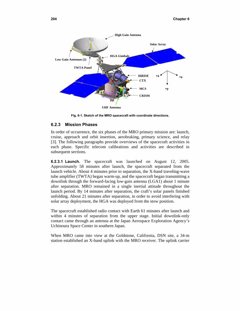
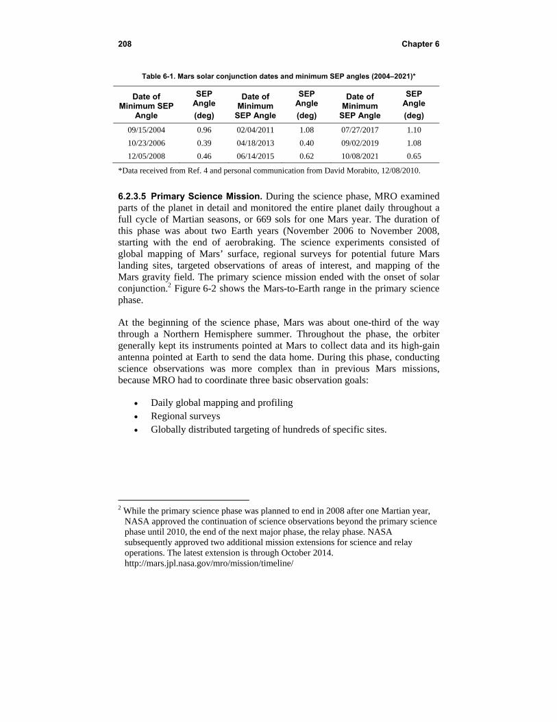
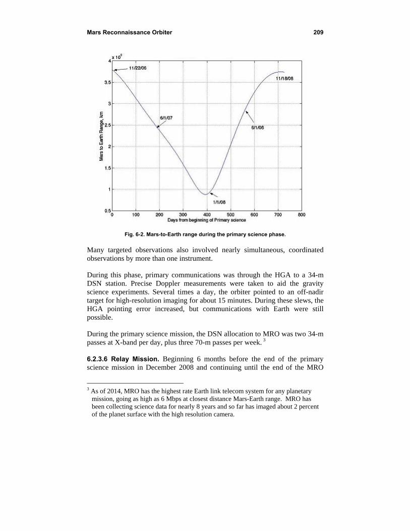
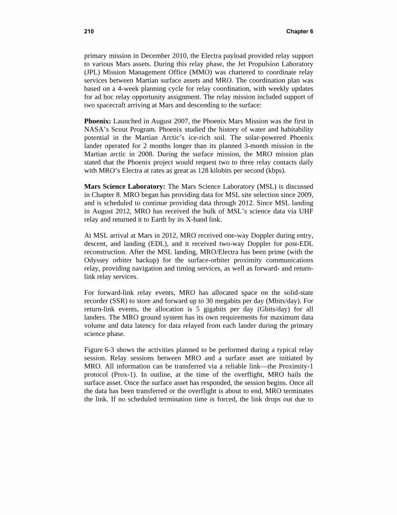
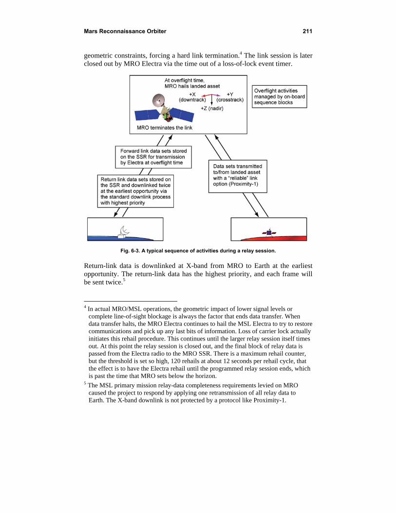
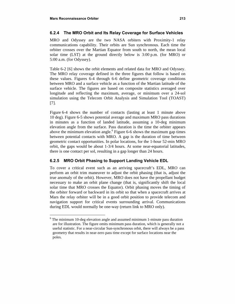
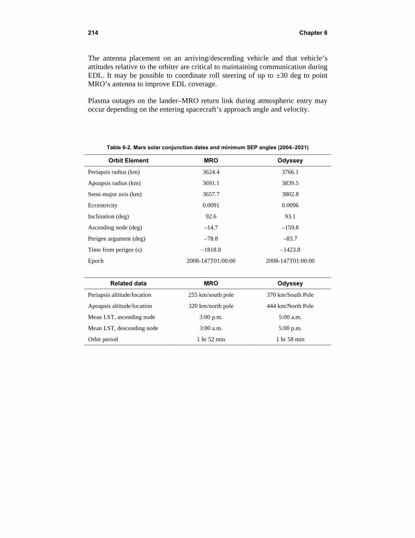
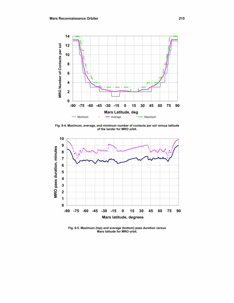
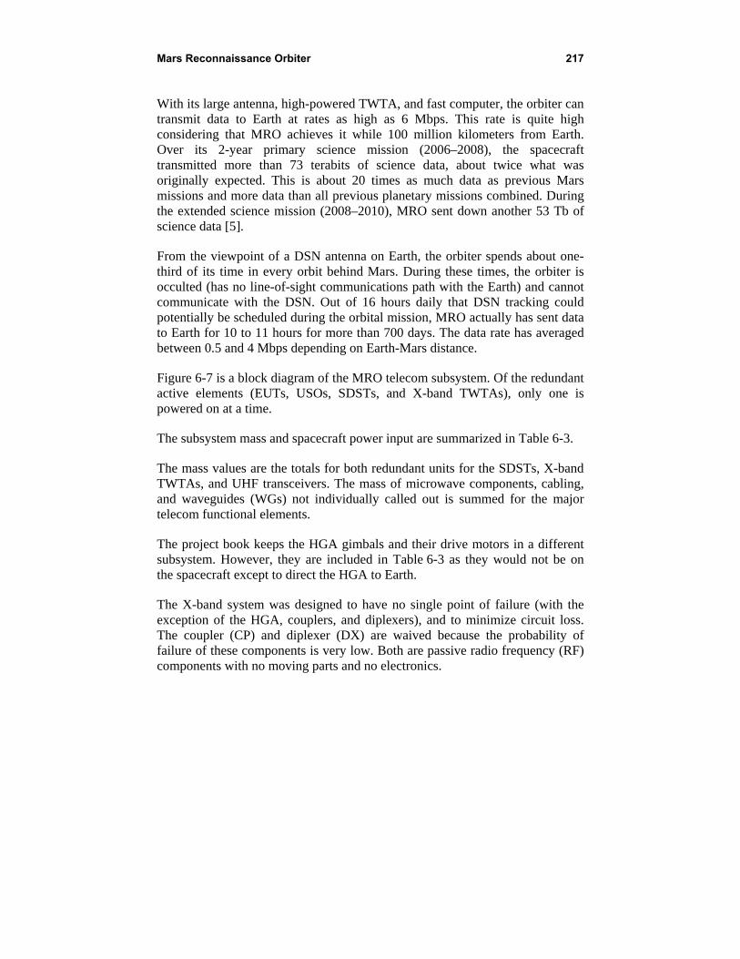
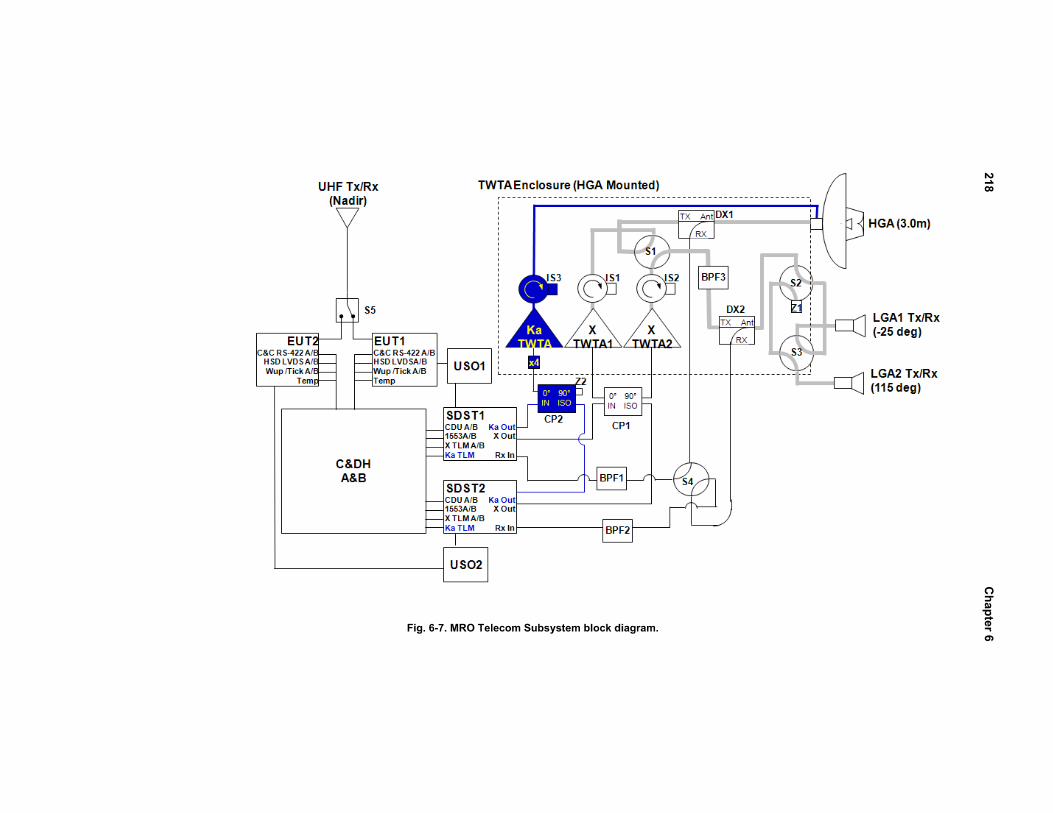
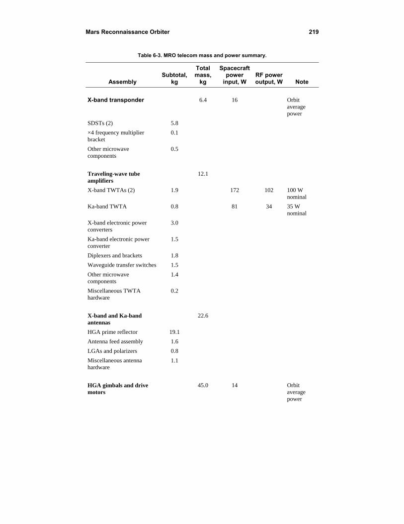
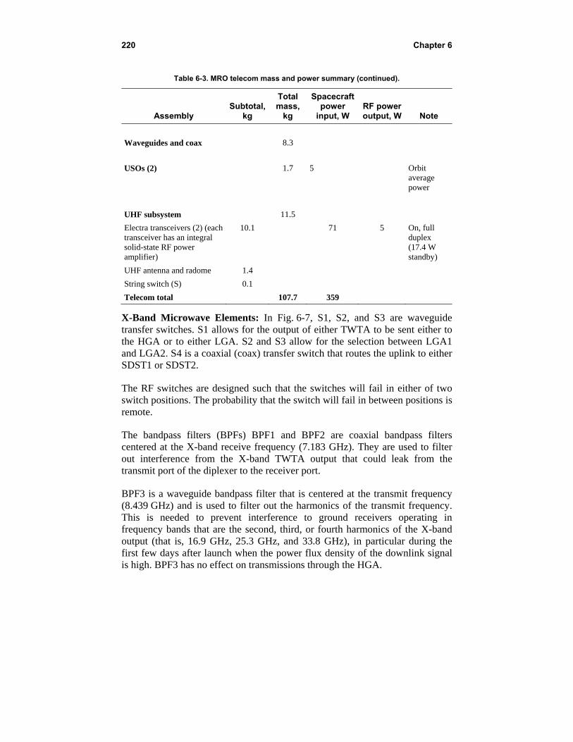
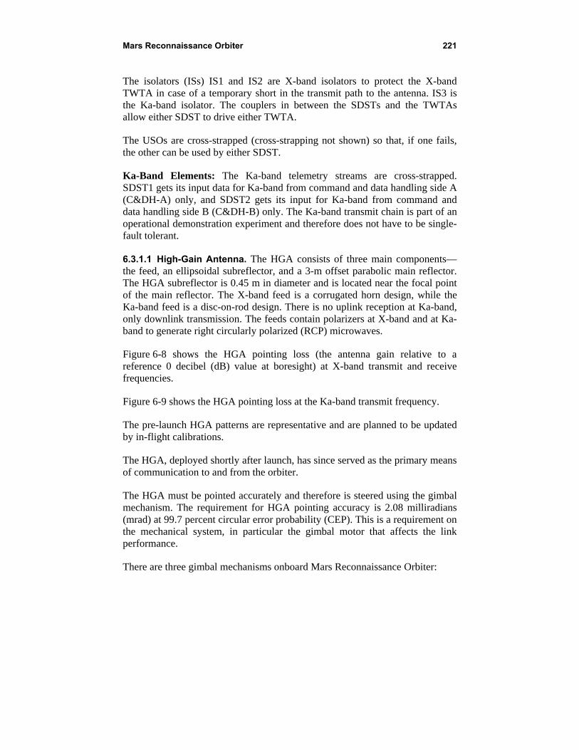
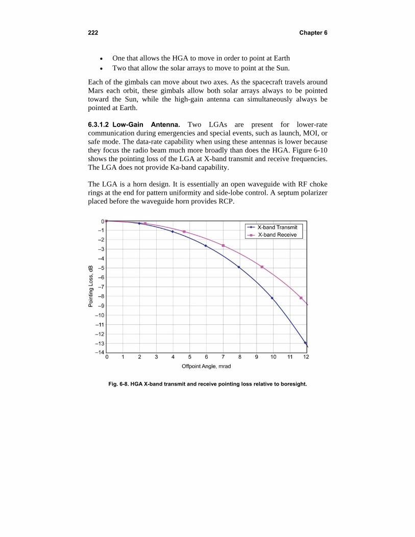
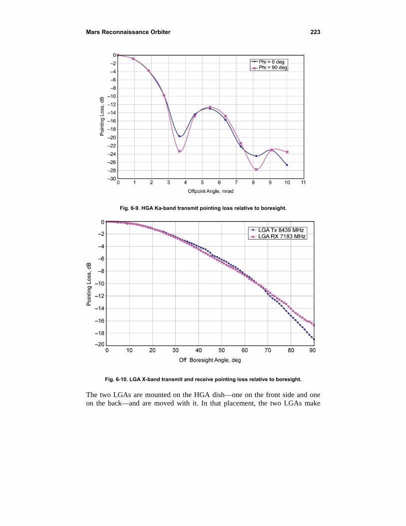
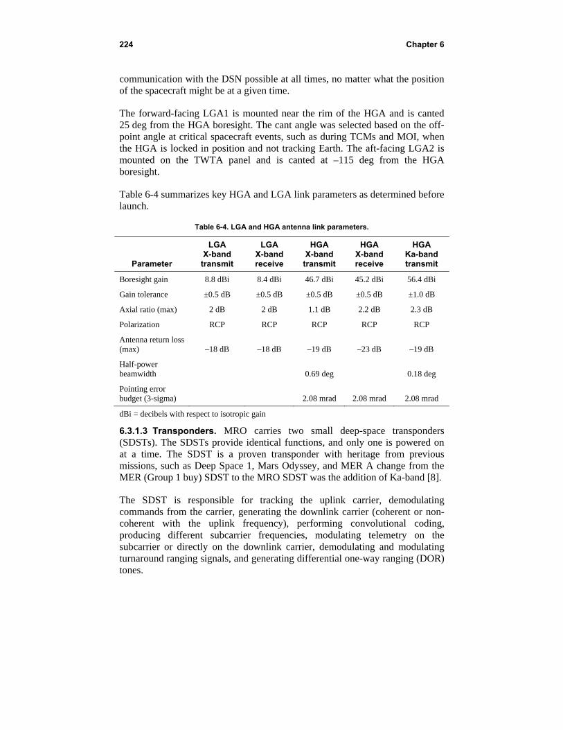
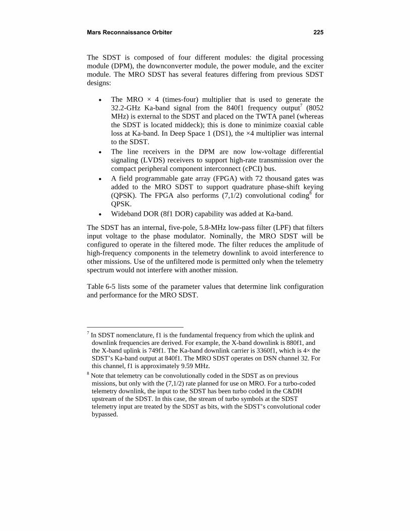
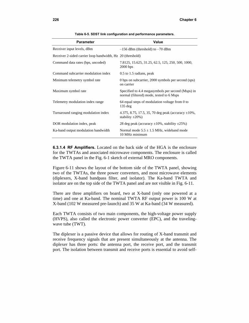
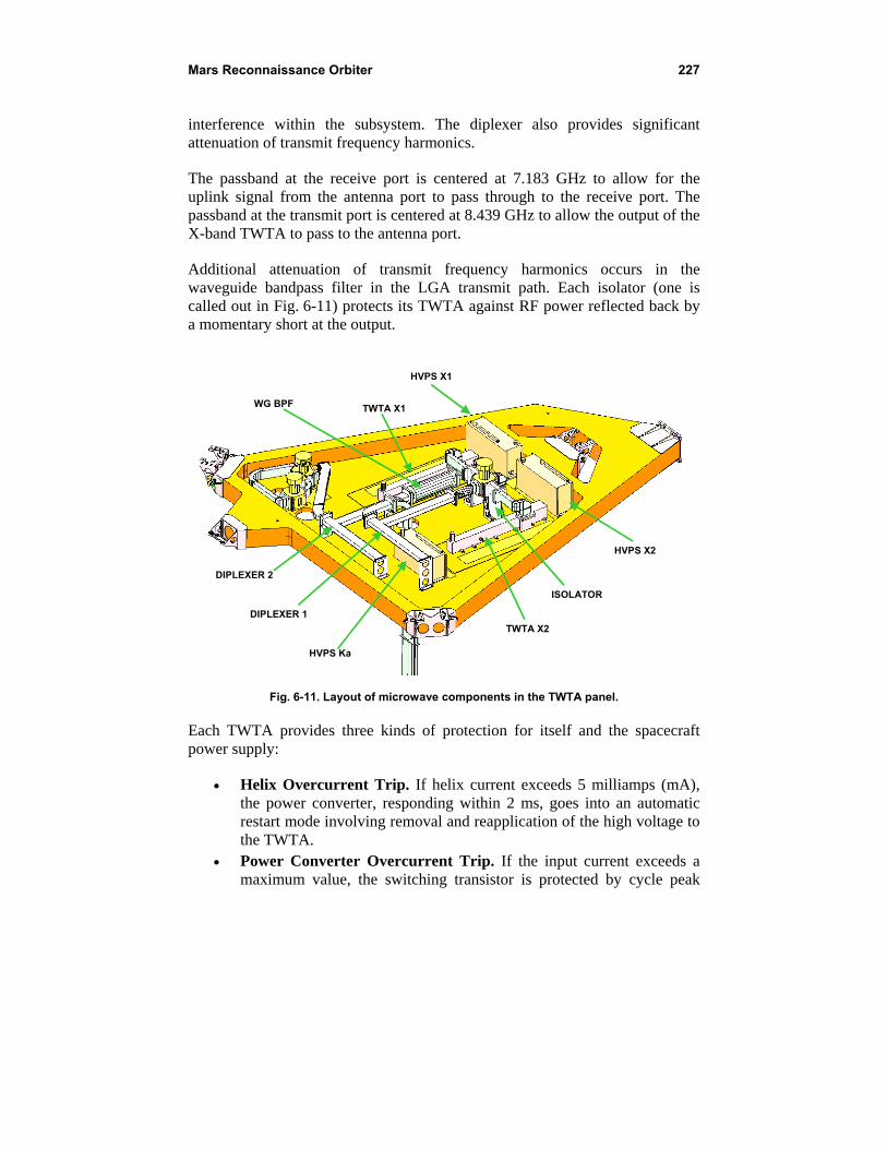
HVPS X1
HVPS X2
TWTA X1
TWTA X2
ISOLATOR
DIPLEXER 1
DIPLEXER 2
HVPS Ka
WG BPF
227 Mars Reconnaissance Orbiter
interference within the subsystem The diplexer also provides significant attenuation of transmit frequency harmonics
The passband at the receive port is centered at 7183 GHz to allow for the uplink signal from the antenna port to pass through to the receive port The passband at the transmit port is centered at 8439 GHz to allow the output of the X-band TWTA to pass to the antenna port
Additional attenuation of transmit frequency harmonics occurs in the waveguide bandpass filter in the LGA transmit path Each isolator (one is called out in Fig 6-11) protects its TWTA against RF power reflected back by a momentary short at the output
HVPS X1
HVPS X2
TWTA X1
TWTA X2
ISOLATOR
DIPLEXER 1
DIPLEXER 2
HVPS Ka
WG BPF
Fig 6-11 Layout of microwave components in the TWTA panel
Each TWTA provides three kinds of protection for itself and the spacecraft power supply
Helix Overcurrent Trip If helix current exceeds 5 milliamps (mA) the power converter responding within 2 ms goes into an automatic restart mode involving removal and reapplication of the high voltage to the TWTA
Power Converter Overcurrent Trip If the input current exceeds a maximum value the switching transistor is protected by cycle peak
228 Chapter 6
current limitation Also after about 2 ms the converter goes into the automatic restart mode
Bus Undervoltage Trip If the bus voltage at the converter input drops below 205 V the high voltage switches off and an undervoltage trip status flag is set When the bus voltage rises above 215 V again the TWTA startup sequence is initiated and preheating begins The preheating lasts about 210 seconds The nominal bus voltage is 28 V
632 UHF Proximity Relay Communications As shown in Fig 6-12 the Electra payload in MRO becomes a network node in the Mars network constellation that provides efficient relay of high-rate in-situ mission science and engineering data The first landing vehicles that are planned to use MROElectra operationally are Phoenix and MSL
Figure 6-13 is a block diagram of the MRO UHF system and its interfaces (IFs) with the command and data handling (CampDH) and SSR systems The EUTs and the USOs (which also support the X-band and Ka-band systems) are redundant The diagram shows the allowable combinations of redundant USOs and EUTs with the CampDH sides and the redundant SSRs
Figure 6-14 is a sketch of the EUT
MARS
EARTH
DSN 34M DSN 70M
PROBE
SCIENCE ORBITER
SCOUT ROVER
ELECTRA PAYLOAD ON-BOARD
Fig 6-12 MRO Electra payload operations concept
MMRROO CampDHCampDH ++
USOB
USO B EUTEUT
SSR-SSR-AA USOA
USO A
Passive
MMRROO CampDHCampDH ++ EUTEUT
Cross-strap
AA
UHFSwitch
UHF Switch
SSR-BSSR-B BB
229 Mars Reconnaissance Orbiter
Fig 6-13 MROElectra UHF block diagram and interfaces with CampDH and SSR
Fig 6-14 Electra UHF transceiver (EUT) assembly
The EUT assembly consists of five modular slices From top to bottom the slices are
Half-duplex overlay (HDO) receiver filter and UHF diplexer Filtering and switch unit (FSU) UHF radio frequency module (RFM the receiver and transmitter) Baseband processor module (BPM) Power supply module (PSM) with integral power amplifier module
The FSU slice in the MRO EUT consists of a high-isolation diplexer the HDO receivetransmit (RT) switch and the coaxial transfer switch The BPM slice interfaces directly with MRO CampDH the MRO SSR the USO and the modules that comprise the EUT
The RFM slice consists of a single-channel UHF transmitter and receiver
230 Chapter 6
The PSM slice consists of the power supply and the driverpower amplifier The PSM provides power to the BPM and under BPM control to the elements of the RFM The PSM slice also includes a power amplifier that amplifies the modulated signal to the appropriate RF output level
The BPM performs all signal processing provides overall EUT control and services the external spacecraft interfaces
Figure 6-15 summarizes the functionality of the modem processor (MP) portion of the BPM in block diagram form which was updated from Ref [9]
ADC = analog-to-digital converter AGC = automatic gain control CLK GEN = clock generator DTTL = data transition tracking loop GSE = ground support equipment SPARC = scalable processor architecture
Fig 6-15 Electra transceiver block diagram
The BPM consists of a 32-bit microprocessor two radiation-hardened program-once field programmable gate arrays (FPGAs) and a large (~1 million gates (Mgate)) reprogrammable FPGA along with a substantial amount of dynamic and static memory The reprogrammable FPGA contains the modem functions
231 Mars Reconnaissance Orbiter
and is reprogrammable post-launch The 32-bit microprocessor manages the EUT and the relay Prox-1 protocol9
In concept one side of the BPM handles the spacecraft interfaces A dedicated 1553 transceiver chip supports the command and telemetry interface to the host CampDH An LVDS interface supports high-rate relay and radiometric data transfers through the high-speed data (HSD) FPGA The other side of the BPM handles the EUT with the housekeeper (HK) FPGA managing control and telemetry signals to and from the EUT front end and the MP FPGA
The main functions of the MP FPGA include
Coding and decoding Modulation and demodulation Carrier symbol and decoder synchronization Prox-1 frame synchronization detection Prox-1 transmit (Tx) and receive (Rx) user data and control data
buffering Receive signal level management automatic gain control (AGC) Radiometric Doppler and open-loop record functions Clock (CLK) and timestamp functions Implementation of the physical layer of the communication link from
baseband to an intermediate frequency (IF)
The MRO Electra does not have an internal clock The clocks for the BPM FPGAs including bit symbol and sample rate clocks are derived from the external USO
Table 6-6 [6] defines the major operating modes functions and constraints for the MRO EUT
MRO Electra implements frequency agility and swappable transmit and receive bands The EUT complies with the CCSDS Prox-1 channel definitions for eight frequency pairs In all Electra supports 16 preset frequency pairs as defined in Table 6-7 [10]
In addition to the 16 preset pairs the MRO Electra radio has the capability to tune its Tx and Rx frequencies across the entire 390-MHz-to-450-MHz band
9 The EUT complies with the Proximity-1 protocol defined by the Consultative Committee for Space Data Standards (CCSDS) in Ref 11 In this chapter the protocol is abbreviated Prox-1
232 Chapter 6
thus any frequency pair combination within this band is possible For half-duplex operation any pair of frequencies will work as an operational pair For full-duplex operation the Tx frequency must be chosen in the range of 435 MHz to 450 MHz and the Rx frequency must be chosen in the range of 390 to 405 MHz
Table 6-6 MROElectra modes functions and performance
Capability Values
Protocol Prox-1 (reliable and expedited link layer protocols)
Frequencies See next section (including Table 6-7)
Modes of operation Half-duplex10 Rx and Tx (no Prox-1 protocol in half duplex)
Full-duplex transceiver
Full-duplex carrier modes Coherent noncoherent
Transceiver RF output power 50 W full duplex 70 W half duplex
Circuit loss EUT to antenna ndash042 dB
Receiver thresholds at ndash1308 dBm (1 kbps) to ndash996 dBm (1024 kbps) coded antenna ndash1260 dBm (1 kbps) to ndash911 dBm (2048 kbps) uncoded
Carrier modulation modes Suppressed carrier residual carrier (60 deg mod index)
Modulation types Residual carrier binary phase-shift keying (BPSK) with bishyphase-L (Manchester) Suppressed-carrier BPSK
Frequency reference Ultra stable oscillator
Rx and Tx symbol rates 1 2 4 8 16 32 64 128 256 512 1024 2048 thousand symbols per second (ksps)
Also adaptive data rate mode
Received signal power range ndash140 to ndash70 dBm
Encoding Uncoded (k = 7 r = 12) convolutional differential symbol coding
Decoding Uncoded (k = 7 r = 12) convolutional (3-bit soft decode)
Scramblingdescrambling V38
Acquisition and tracking Second-order phase locked loop (PLL) with loop bandwidth loop 10 Hz to 10 kHz (for received signal from ndash140 dBm to ndash
70 dBm)
Tracking range and rate plusmn20 kHz plusmn200 Hzs
10 The term ldquofull duplexrdquo is used by MRO in the conventional sense of simultaneous forward and return link capability at separate frequencies The term ldquohalf duplexrdquo means that Electrarsquos transmitter and receiver are not on simultaneously even though the forward and return links may be on separate frequencies
233 Mars Reconnaissance Orbiter
The MRO Electra payload provides a single nadir-looking (vertical down to Mars) UHF LGA The antenna shares the nadir deck with science payloads Some parts of these nearby payloads that are responsive at UHF frequencies couple with the antenna and distort its nominal gain pattern To compensate for this the MRO mission plan allows for spacecraft roll steering of up to 30 deg to point the better parts of the UHF antenna pattern toward the surface user The orbiter sets up for this pass by roll steering to a fixed roll angle The Electra payload performs the pass and then the orbiter rolls back to the standard nadir pointing position
Table 6-7 CCSDS Prox-1 ldquoBlue Bookrdquo channel numbers and ldquopresetrdquo Electra frequencies
CCSDS MRO Preset CCSDS MRO Preset Forward Forward Return Return
Channel Number
Frequency (MHz)
Frequency (MHz)
Frequency (MHz)
Frequency (MHz)
0 4371 4371 401585625 401585625
1 4356 4356 4044 4044
2 4392 4392 3975 3975
3 4446 4446 3939 3939
4 435 to 450 436 390 to 405 4014
5 435 to 450 438 390 to 405 402
6 435 to 450 440 390 to 405 4026
7 435 to 450 441 390 to 405 4032
8 442 391
9 4425 392
10 443 393
11 445 395
12 446 3955
13 447 396
14 448 399
15 449 400
Figures 6-16 (4371 MHz) and 6-17 (4016 MHz) show antenna gain in dBi versus angle from boresight These angles from boresight are called cone or theta angles In each figure the solid curve is the average gain over cuts made in the axis orthogonal to cone Angles in the orthogonal axis are called clock or phi angles The dotted curves above and below the solid curve are the gains for
Off boresight angle (theta) degrees
Fig 6-16 MRO 4371-MHz gain pattern
-4
-3
-2
-1
0
1
2
3
4
-5
-3
-2
-1
0
1
2
3
4
5
6
MR
O 4
371
MH
z (r
cp) g
ain
dB
I
0 15 30 45 60
MR
O 4
016
MH
z (r
cp) g
ain
dB
i
75
234 Chapter 6
the best-case and worst-case clock cut respectively The antenna is RCP for both the forward and return links
The MRO Electra transceiver is compatible with the CCSDS Proximity-1 Space Link Protocol [10 11] Prox-1 transfer frames are sent on both the forward link (from the orbiter to the surface vehicle) and the return link (surface back to the orbiter) using the Prox-1 protocol link management in either reliable (retransmission) or expedited (no retransmission) mode In retransmission mode an automatic repeat queuing (ARQ) protocol is utilized to request retransmission of any proximity frames that are not received error-free MRO also provides a relay service (called ldquoraw datardquo) not utilizing the Prox-1 protocol The orbiter also provides a form of Doppler data and a form of open-loop data These data types or services are defined in the following
0 15 30 45 60 75 Off boresight angle (theta) degrees
Fig 6-17 MRO 4016-MHz gain pattern
235 Mars Reconnaissance Orbiter
6321 Proximity-1 Data Typically the MRO Electra will initiate a Prox-1 session by sending a string of ldquohailrdquo data packets while looking for a response from the specific lander identified in the hail packet This standard operating procedure can be reversedmdashthat is lander-initiated relay sessions are possible The hail includes information describing the session operating mode for both the forward and return link directions This includes among other things operating frequency data rate and channel-coding mode
6322 Time-Stamp Packets Time-stamp data consist of snapshots of the local Electra clock corresponding to the ingress or egress times of Prox-1 frame-synchronization markers Thus time stamp data is only collected in conjunction with Prox-1 mode operations The time stamps are paired with corresponding Prox-1 frame sequence numbers and noted as arriving or departing frames If the other end of the relay link is also capable of collecting Prox-1 frame time stamps the collection of these time stamps at both ends of the link can be used as a form of dual 1-way ranging and used to correlate clocks on the lander and orbiter
6323 Raw Data In raw data mode there is no hailing or link establishment protocol nor is there any session data management or accounting protocol A link is established by time sequence transmissions and reception at both ends of the link In addition to coordinated sequence timing both sides of the link must agree beforehand to the same data link mode settingsmdashfor example frequencies data rates and coding
6324 Phase and Power Data MROrsquos Electra transceiver can sample and record the phase and power level of a phase-locked received carrier signal This radiometric information is highly accurate (being based on the MRO USO signal and with successive samples tied directly to the USO-based local clock) Each sample contains phase AGC power in-phase (I) amplitude quadrature (Q) amplitude and a USO-based time These data form the basis for a Doppler metric The 160 bit data format is shown below
Phase and Power sample format
6325 IQ (Open Loop) Record Data MROrsquos Electra transceiver can capture complex in-phasequadrature (IQ) samples of the received signal down-converted to baseband at sample rates as fast as 150000 samplessecond This mode is known as open-loop record and is primarily used in support of events like EDL where there is a concern that high signal dynamics or low signal
IQ (open loop) sample non-time-coded format
236 Chapter 6
levels will prevent real-time demodulation of the signal in the Electra transceiver These open loop record samples are passed to the MRO solid state recorder (SSR) and later forwarded to Earth where a software receiver and spectrum analysis tools can be used to demodulate the signal and to decipher the signal dynamics In addition to the complex IQ samples the AGC level is also captured for each sample This allows open loop record to work over the full receive signal level range of the Electra radio and still allow for faithful reconstruction of the received signal later on Earth
There are two data modes for open loop record The first mode captures the USO clock as part of the sample data This clock-stamped format is used for the first data sample and occasional later samples to establish a clock reference to the sample data Most of the open loop record samples do not include a time stamp and the time of each sample is inferred from the sample count and the sample frequency that is phase locked to the USO clock tick The two data formats are shown below
IQ (open loop) sample time-coded format
633 Ka-Band Operational Demonstration The MRO spacecraft has a fully functioning Ka-band downlink equipment suite comparable to that for the X-band downlink including
A one-way carrier (USO or auxiliary oscillator driven) or a two-way coherent carrier (using the X-band uplink carrier frequency reference)
Modulation of telemetry with any of the available data rates encoding types and modulation index values
Modulation of turnaround ranging from the X-band uplink with a settable modulation index
Modulation of differential one-way ranging tones more widely spaced than at X band Ka-band tones are 76 MHz from the carrier as compared with X-band tones at 19 MHz
237 Mars Reconnaissance Orbiter
The Ka-band components of the subsystem include a times4 (times-four) multiplier a Ka-band TWTA and its power converter a Ka-band feed element in the HGA and other microwave parts as defined in Section 531
Deep Space Network 34-m antennas capable of receiving Ka-band are requested twice per week during the prime science mission as part of the demonstration
64 Ground Data System
641 Deep Space Network The three primary DSN ground complexes are located near Goldstone (California) Madrid (Spain) and Canberra (Australia) The DSN antennas are categorized according to their diameter and performance During cruise and orbit operations MRO was allocated use of the 70-m antenna subnet the 34-m beam-waveguide (BWG) antenna subnet and the 34-m high-efficiency (HEF) antenna subnet
MRO used the 70-m antennas to support MOI and may require them for emergency mode communications (safe mode operations on the LGA)
MRO depends on the 34-m BWG antennas for the vast majority of the mission telemetry and commanding The BWG antennas differ from the HEF antennas in that beam-waveguide optics (mainly consisting of a series of small mirrors) are used to direct microwave energy from the region above the main reflector to a location at the base of the antenna (typically the pedestal room) This allows for easier access to the microwave equipment and the positional stability allows for use of state-of-the-art ultra-low noise amplifier and feed designs
MRO may alternatively be allocated 34-m HEF stations (one at each complex) for passes that do not require Ka-band downlink capability Because the low-noise amplifier (LNA) is located near the HEF antenna feed the gain-to-noise temperature ratio GT is about 1 dB better than in the BWG antennas
With the new X-X-Ka-band (X-band up X-band down Ka-band down) feed and LNA upgrades to the 34-m BWG antennas the upgraded 34-m BWG stations have a slightly higher gain over temperature (GT)
The gain noise temperature and pointing characteristics of the antennas are listed in the DSN Telecommunications Link Design Handbook [12]
238 Chapter 6
642 Ka-Band Demonstration Requirements The Ka-band demonstration includes an assessment of the DSNrsquos readiness to track Ka-band signals from deep-space missions One operational station (DSS-25) tracked the ldquonew technologyrdquo Ka-band downlink from Deep Space 1 in 1998ndash1999 and the DSN has tracked Ka-band sporadically for Cassini radio science activities Several of the 34-m stations have Ka-band downlink capability to support the MRO Ka-band operational demonstration These are DSS-25 and DSS-26 at Goldstone in California DSS-34 near Canberra in Australia and DSS-55 near Madrid in Spain
The 34-m BWG Ka-band beam width is less than 18 millidegrees (mdeg) The basic antenna pointing capabilities required for the Ka-band demonstration include
ldquoBlind-pointingrdquo of the antenna (computer driven without input from the received downlink) must be better than 10 mdeg [13] so that the monopulse system (active pointing) will be able to operate
The monopulse must be operational (without it pointing errors may cause link degradation of 4ndash5 dB)
Besides the normal functions of telemetry demodulation and decoding and measurements of Doppler two-way ranging and delta-DOR the Ka-band demonstration requires the following monitor data generation capabilities
Accurate measurement by the operational receiver of signal-to-noise ratio (SNR) particularly symbol SNR
Accurate measurement by the operational receiver of system noise temperature (SNT)
Sampling of receiver monitor data at the specified 5-second interval with prompt delivery of the data to the MRO database
These additional requirements will enable the demonstration to identify data outages caused by weather events and to separate them from outages caused by other phenomena
643 Ground Data Network Flow for Relay Data through Electra Figure 6-18 shows the MRO science data flow processing and accountability mechanisms In the context of the five Electra relay data types (Prox-1 data raw data time stamps phase and power data and open-loop data) all are ldquoscience datardquo The features highlighted in red identify the flow of Electra relay data to the ground
DSN Stations
Transfer Frames wrapped in SFDUs (Standard Format Data Unit)
Telemetry Processing
Packets containing DataPDUs MetadataPDUs End-of-filePDUs
TDS-based data storage
routing distribution
CFDP Processing
DOM Distributed
Object Manager
MRO Mission
Operations at JPL
DSMS Telemetry Service
DSMS CFDP Service
Re-transmission cmd Spacecraft Payload
SHARAD
ELECTRA
CTX
HiRISE
CRISM
MCS
MARCI
SSR Rate Buffer
SC Flight Computer - Data Compression - Packetization - AOS Framing - Virtual ChannelPriority - Sequence amp Cmd
Processing
Telecom Subsyst
Other SC Subsystems
Uplink Data
Relay Data Products amp Accounting File
MRO SC Operations At LMA
AOS Frame accounting
Science Ops amp Data Processing
Planetary Data System
SHARAD (ASI)
CRISM (APL)
HiRISE (UA)
Gravity (GWU)
CTX amp MARCI (MSSS)
Atmos Sci (MIT)
MCS (JPL)
PDS labeled Science Data Products
Raw Science Data Server
(RSDS)
Surface Assets Ops1
3
6
6
1
7
7
8
9
Science Product amp Accounting Files
5
3
10
b
b
a MROSPs
MROCIPs
c MRO CFDP PDUs
d
d AOS Frames
e
e Observation ID Priority etc
8
9
ONC
SSR Framed Data Storage
AOS Framed Data
Inst SW
c
a
d
Acq Time ERT SNR Etc
Electra Ops
Electra 5Gbit
5 Science Product amp Metadata Files 10CFDP Transaction Monitor amp control
APL = (Johns Hopkins University) Applied Physics Laboratory CIP and SP = instrument output data DOM = Distributed Object Manager GWU = George Washington University HiRISE = High Resolution Imaging Science Experiment LMA = Lockheed Martin Aerospace MSSS = Malin Space Science Systems UA = University of Arizona
Fig 6-18 MRO Electra science data flow
239 Mars Reconnaissance Orbiter
Electra relay return-link data are routed over a shared LVDS interface to a dedicated SSR hard partition When collecting data from Electra the SSRrsquos Electra interface software limits the amount of data to the space in the Electra partition minus the amount of not-yet-read data in the partition The software will issue a telemetry event record with the difference between actual and planned sizes of the data collection
In Fig 6-18 telemetry processing extracts from the MRO telemetry stream the CCSDS advanced orbiting systems (AOS) frames containing MRO CCSDS source packets AOS frames containing telemetry from Electra are processed to extract MRO science protocol packets
240 Chapter 6
These source packets are provided to the CCSDS File Delivery Protocol (CFDP) process running on the ground which finds the MRO CFDP protocol data units (PDUs) and reconstructs the Electra pass product Given that there may be gaps in the telemetry stream retransmissions may be requested from the spacecraft on the AOS frame level Associated with the Electra pass product will be a detached Planetary Data System (PDS) label which will contain metadata that describe the circumstances of the collection for example MRO identifier orbit and so forth There also will be a CFDP transaction report on the holes if any in the Electra pass product
A second run of the CFDP process will take the Electra pass product and search for Electra CFDP PDUs to extract the PDUs for each Electra sub-product [relay (Prox-1 data) time stamp raw data phase and power and open-loop I and Q data]
Each Electra relay telemetry product consists of a binary product file which varies for each product type as well as a CFDP transaction log file and a detached American Standard Code for Information Interchange (ASCII) label
Figure 6-19 shows the relay pass product from the Ground Data System (GDS) and Fig 6-20 shows the relay data product delivered The pass product is a binary file with the CFDP PDUs while the data product is a binary file with the Prox-1 transfer frames
Fig 6-19 Electra relay pass product output from GDS
241 Mars Reconnaissance Orbiter
Fig 6-20 Electra relay data product from GDS
65 X-Band Telecom Operations
651 Cruise Calibrations Planned telecom cruise calibrations are summarized in Table 6-8 During the X-band and Ka-band HGA calibration the spacecraft articulates the HGA through a grid-like pattern (raster scan) about the pre-launch antenna boresight By monitoring the received signal strength the calibration determines if the HGA phase center has shifted during launch
Table 6-8 Telecom cruise calibrations
Calibration type Date Comments
X-band LGA performance Launch + 9 days Perform as part of normal LGA ops Spacecraft slewing not required
X-band HGA pattern calibration Launch + 24 days Raster scan simultaneous with Ka-band HGA calibration
Ka-band HGA pattern calibration Launch + 24 days
Electra UHF pattern characterization Launch + 40 days Conical scan
Electra UHF performance Launch + 40 days
X-band Delta DOR checkout Launch + 40 days Done once per week starting at L + 40 d
Ka-band wideband delta-DOR Launch + 40 days Done once per week starting at checkout L + 40 d
242 Chapter 6
652 MOI Telecom Configurations The main engine burn for MOI began at 2124 universal time coordinated (UTC) referenced to Earth received time (ERT) the time this event was seen on the Earth Ninety minutes prior to this the telecom path was switched to LGA1 which then was used throughout the orbit insertion process Thirteen minutes prior to engine start the spacecraft began a slew to MOI attitude It ended the slew 5 minutes before engine start and its inertial attitude remained fixed at this position throughout MOI At the beginning of the burn LGA1 was boresighted at Earth By the time MRO entered solar eclipse (start + 21 minutes) and was occulted from Earth by Mars (2 minutes later) the offshyboresight angle was around 20 to 25 deg The burn ended at 2151 ERT the turn back to Earth ended at 2213 and occultation ended (downlink reached the Earth) at 2216 ERT
During the MOI itself the DSN supported downlink telemetry with two 70-m antenna stations simultaneously (DSS 14 and DSS 63 had overlapping coverage) Figure 6-21 shows the approximate elevation angles for the 70-m antennas on March 10 2006
10
20
30
40
50
60
70
80
90
Stat
ion
Elev
atio
n A
ngle
deg
DSS 63 Madrid
DSS 43 Canberra
DSS 14 Goldstone
1200 130 300 430 600 730 900 1030 1200 130 300 430 600 730 900 1030 1200 AM AM AM AM AM AM AM AM PM PM PM PM PM PM PM PM AM
Time
Fig 6-21 Station elevation angles on day of Mars Orbit Insertion
Following re-acquisition with LGA1 the X-band system was transitioned back to the HGA for spacecraft checkout Navigation began to collect two-way radiometric data and to perform orbit determination of the capture orbit
243 Mars Reconnaissance Orbiter
653 Aerobraking Telecom Configurations During aerobraking the two main activities are the drag passes and the aerobraking maneuvers (ABMs) The drag passes occur at the capture orbit perigee and the spacecraft is oriented with the velocity vector in order to maximize the drag coefficient The ABMs typically are conducted at the apogee of the capture orbit and are used to adjust the orbit after the drag pass if needed
At 16 minutes prior to the start of each drag pass an onboard sequence configures the telecom system to transmit a carrier-only downlink over LGA1 In addition the uplink bit rate is switched to 78125 bps the minimum available rate After 1 minute for the DSN to lock up to the carrier the HGA is locked into position and communications are through LGA1 throughout the duration of the drag pass Ten minutes after the end of the drag pass the sequence restores nominal downlink through the HGA
Likewise 16 minutes before the beginning of the ABM the sequence configures the telecom system to transmit a carrier-only downlink through LGA1 This remains the telecom configuration until 15 minutes after the conclusion of the ABM at which time the nominal downlink through the HGA is re-established
654 Downlink Telemetry Modulation and Coding The MRO project data volume goal for full mission success is to return more than 26 terabits of science data from Mars during its primary science phase which exceeds any previous deep-space mission by more than an order of magnitude
The following kinds of modulation are used on MRO [14]
BPSK on a subcarrier with the subcarrier modulating the carrier
BPSK directly on the carrier
QPSK directly on the carrier
QPSK modulation capability by the SDST allows for twice the data rate to be transmitted through the same bandwidth as compared with the BPSK used in previous missions Sequential tone ranging is not possible with QPSK because of the fully suppressed carrier
Error-correcting codes as defined in Tables 6-9 through 6-14 are used on the downlink to the DSN The table referenced in the title of each subsection summarizes the main MRO configuration items (bit rate and symbol rate
244 Chapter 6
modulation type modulation index and station receiver loop type) and receiver thresholds
In the following subsections the symbol rate is defined as the output of the SDST (that is channel symbols) and the information bit rate is defined as the frame bit rate coming into the CampDH (at point ldquodrdquo in Fig 6-18)
Table 6-9 Emergency mode (712) + RS (short frame) concatenated code
TLM only TLM + RNG Lo
TLM + RNG Hi
Code Type Framed Bit Rate bps
Symbol Rate sps
Modulation Type
Subcarr Freq (kHz)
Tlm Mod Index (deg)
Carrier Loop Type
Threshold PtNo
(dB-Hz)
Threshold PtNo
(dB-Hz)
Threshold PtNo
(dB-Hz) (712)+RS
(I=1) 344 80 Squarewave
Subcar 25 58 Residual 214 217 225 (712)+RS Squarewave
(I=1) 1375 320 Subcar 25 71 Residual 262 265 273
Table 6-10 (712) + RS (long frame) concatenated code
TLM only TLM + RNG Lo
TLM + RNG Hi
Code Type Framed Bit Rate bps
Symbol Rate sps
Modulation Type
Subcarr Freq (kHz)
Tlm Mod Index (deg)
Carrier Loop Type
Threshold PtNo
(dB-Hz)
Threshold PtNo
(dB-Hz)
Threshold PtNo
(dB-Hz) (712)+RS
(I=5) 5569 1280 Squarewave
Subcar 25 72 Residual 312 315 323 (712)+RS
(I=5) 17404 4000 Squarewave
Subcar 25 72 Residual 360 363 371 (712)+RS
(I=5) 278468 64000 Squarewave
Subcar 375 72 Residual 479 482 490 (712)+RS
(I=5) 870211 200000 Squarewave
Subcar 375 72 Residual 528 531 539 (712)+RS
(I=5) 1392338 320000 BPSK Direct
Mod None 72 Residual 549 552 559 (712)+RS
(I=5) 2088507 480000 BPSK Direct
Mod None 72 Residual 566 569 577 (712)+RS
(I=5) 3480844 800000 BPSK Direct
Mod None 72 Residual 588 591 599 (712)+RS
(I=5) 6961689 1600000 BPSK Direct
Mod None 72 Residual 618 622 636 (712)+RS
(I=5) 10442533 2400000 QPSK None 82 Suppressed 634 - -(712)+RS
(I=5) 13053167 3000000 QPSK None 82 Suppressed 643 - -(712)+RS
(I=5) 4786161 1100000 BPSK Direct
Mod None 72 Residual 602 606 620 (712)+RS
(I=5) 17404222 4000000 QPSK None 82 Suppressed 656 - -(712)+RS
(I=5) 26106333 6000000 QPSK None 82 Suppressed 673 - -
Table 6-11 Turbo code rate 12
TLM only TLM + RNG Lo
TLM + RNG Hi
Code Type Framed Bit Rate bps
Symbol Rate sps
Modulation Type
Subcarr Freq (kHz)
Tlm Mod Index (deg)
Carrier Loop Type
Threshold PtNo
(dB-Hz)
Threshold PtNo
(dB-Hz)
Threshold PtNo
(dB-Hz)
Turbo 12 7456454 1500000 BPSK Direct
Mod None 72 Residual 607 611 625
Turbo 12 14912908 3000000 QPSK None 82 Suppressed 635 - -
245Mars Reconnaissance Orbiter
Table 6-12 Turbo code rate 13
TLM only TLM + RNG Lo
TLM + RNG Hi
Code Type Framed Bit Rate bps
Symbol Rate sps
Modulation Type
Subcarr Freq (kHz)
Tlm Mod Index (deg)
Carrier Loop Type
Threshold PtNo
(dB-Hz)
Threshold PtNo
(dB-Hz)
Threshold PtNo
(dB-Hz)
Turbo 13 662796 200000 Squarewave
Subcar 375 72 Residual 496 499 507
Turbo 13 1325592 400000 BPSK Direct
Mod None 72 Residual 526 529 537
Turbo 13 1988388 600000 BPSK Direct
Mod None 72 Residual 544 547 555
Turbo 13 4970969 1500000 BPSK Direct
Mod None 72 Residual 583 587 601
Turbo 13 6627959 2000000 BPSK Direct
Mod None 72 Residual 596 600 614
Turbo 13 7953551 2400000 QPSK None 82 Suppressed 601 - -
Turbo 13 9941938 3000000 QPSK None 82 Suppressed 611 - -
Turbo 13 13255918 4000000 QPSK None 82 Suppressed 624 - -
Table 6-13 Turbo code rate 16
TLM only TLM + RNG Lo
TLM + RNG Hi
Code Type Framed Bit Rate bps
Symbol Rate sps
Modulation Type
Subcarr Freq (kHz)
Tlm Mod Index (deg)
Carrier Loop Type
Threshold PtNo
(dB-Hz)
Threshold PtNo
(dB-Hz)
Threshold PtNo
(dB-Hz)
Turbo 16 3313979 2000000 BPSK Direct
Mod None 72 Residual 561 565 578
Turbo 16 4970969 3000000 QPSK None 82 Suppressed 576 - -
Turbo 16 6627959 4000000 QPSK None 82 Suppressed 589 - -
Turbo 16 9941938 6000000 QPSK None 82 Suppressed 606 - -
Table 6-14 RS coding only (long frame)
TLM only TLM + RNG Lo
TLM + RNG Hi
Code Type Framed Bit Rate bps
Symbol Rate sps
Modulation Type
Subcarr Freq (kHz)
Tlm Mod Index (deg)
Carrier Loop Type
Threshold PtNo
(dB-Hz)
Threshold PtNo
(dB-Hz)
Threshold PtNo
(dB-Hz)
RS only (I=5) 1305317 150000 Squarewave
Subcar 375 72 Residual 582 585 593
RS only (I=5) 17404222 2000000 BPSK Direct
Mod None 72 Residual 695 699 712
RS only (I=5) 20885066 2400000 QPSK None 82 Suppressed 700 - -
RS only (I=5) 23930805 2750000 QPSK None 82 Suppressed 706 - -
RS only (I=5) 26106333 3000000 QPSK None 82 Suppressed 710 - -
RS only (I=5) 28716966 3300000 QPSK None 82 Suppressed 714 - -
RS only (I=5) 34808444 4000000 QPSK None 82 Suppressed 723 - -
RS only (I=5) 52212666 6000000 QPSK None 82 Suppressed 740 - -
246 Chapter 6
6541 Short Frame Concatenated (Table 6-9) The [(712) convolutional + ReedndashSolomon (RS) (short frame)] concatenated code will be used only for the emergency mode 3438 bps and a MOI data rate of 139 bps The 3438 bit rate is chosen for heritage reasons with the coded bit rate out of the CampDH uplinkndash downlink (ULDL) card at 40 bps and the SDST output symbol rate at 80 symbols per second (sps)
6542 Long-Frame Concatenated (Table 6-10) The [(712) convolutional + RS (long-frame)] concatenated code has been proven in many prior missions and is used to cover the largest span of bit rates Because of bandwidth limitations the maximum rate for the concatenated code downlink is a bit rate of 33 Mbps at the SDST input and a symbol rate of 66 megasymbols per second (Msps) at the SDST output If interference with another project is an issue maximum rates are 2 Mbps and 4 Msps
6543 Turbo Code (Tables 6-11 Through 6-13) Turbo codes are to be used for bit rates above 32 kbps This capability implemented in CampDH hardware provides more link margin as compared with convolutional codes of the same code rate Currently the maximum decode rate of the ground turbo decoder limits use of turbo codes to 16 Mbps and below If interference to another project could occur the limit is 4 Msps (SDST output channel rate)
6544 RS-Only (Table 6-14) The RS-only coding is used primarily for very high data rates in situations where MRO is close enough to Earth that coding gain is less important (such as in early cruise and during MarsndashEarth closest approach) The maximum rate for RS-only data is 66 Mbps (66 Msps) If interference to another project could occur the limit is 4 Mbps (4 Msps)
655 Coordinating MRO and MER X-Band Operations The MRO SDST operates on DSN channel 32 When it became apparent that MER-A (also on channel 32) and MER-B (on channel 29) were likely to still be active on Mars at MRO arrival a coordination plan was agreed to between the projects The original agreement excerpted below focused on the MRO MOI period It has been extended to the MRO aerobraking phase and likely will require updates for the primary science phase
According to the general agreement as shown in Table 6-15 MER-A (ldquoSpiritrdquo) would forego use of the DSN during the MOI and aerobraking critical event periods This agreement to ensure MRO safety documents the dates chosen for MER-A to use (and not use) DSN during this period
Prior to the start of the critical aerobraking period (MarchndashSeptember 2006) MRO and MER jointly developed a coordination plan to reduce the chances of
247 Mars Reconnaissance Orbiter
an inadvertent MRO channel 32 uplink interfering with MER channel 32 commanding or vice versa The plan called for MER to define a one-hour period for each MER-A sol when the project would do any required X-band commanding for that sol This period is outlined in Fig 6-22 Times in the figure go from left to right on two rows The top row is spacecraft event time at Mars The bottom row is Earth transmit time at the station
Table 6-15 MROndashMER agreement on channel 32 X-band uplink use
Schedule Agreement
Before February 28 MER-A operates normally X-band downlink (direct to Earth) and uplink (direct from Earth) as needed
Starting February 28 2006-059T0000 - 2006-060T0000
No MER-A X-band operations on channel 32
March 1ndash5 MER-A X-band uplink allowed
March 6ndash12 2006-065T0000 - 2006-072T0000
(MOI was March 10) No MER-A X-band operations on channel 32
March 13 through aerobraking MER-A X-band uplink coordinated weekly with Mission exit (ABX) ndash 2 weeks Planning and Sequencing Team (MPST) to avoid overlaps with
MRO uplink windows MER-A will not use X-band uplinks if in conflict with MRO uplink windows
ABX ndash 2 weeks through ABX No MER X-band operations (UHF with Odyssey)
Figure 6-22 and the acronym MUKOW (MRO uplink keep out window) define the goal of this coordination11 The term ldquokeep outrdquo refers to scheduling the DSN uplink to MRO to be turned off at an agreed-to time to keep it out of the MER SDST receiver when MER uplinking is required and to scheduling the uplink to MER to be turned off to keep it out of the MRO SDST receiver when MRO uplinking is required The scheduling is required as part of the coordination agreement between the projects because the projects have individual planning processes and the DSN stations allocated to different projects are operated separately
Every two weeks MER delivers a spreadsheet file with two entries in each row (1) the time the DSN transmitter supporting MRO is to be turned off and (2) the time the DSN transmitter subsequently supporting MER-A is to be turned off
11 The MUKOW coordination process has continued through the extended science phase (ending September 2010) and will continue into subsequent mission phases of the MRO and MER projects as long as DSN support of MRO spacecraft and the Spirit Rover X-band activity continues
248 C
hapter 6Fig 6-22 MRO uplink keep out window (MUKOW) timing
249 Mars Reconnaissance Orbiter
The MER and MRO SDSTs have a ldquoState 1 timeoutrdquo duration of 10 minutes between when the SDST receiver goes one way (in response to the station transmitter turn off) and when it forces its phase-locked loop (PLL) to best-lock frequency Each project uses a ldquosweep acquisitionrdquo uplink frequency profile by the station to ensure the stationrsquos uplink carrier goes through the actual (temperature-dependent) best-lock frequency
The coordination process as developed on a basic weekly schedule allows for negotiated updates (including cancellations or additions) of keep-out times to meet significant needs of either project These could include changes in MRO aerobraking times or anomalies that occur with either project
Although the agreement primarily affects uplink operations both MER spacecraft occasionally require a direct-to-Earth (DTE) X-band downlink for onboard spacecraft clock correlation with UTC Also both MER spacecraft rely on the detection by the DSN station of an unmodulated X-band downlink carrier (ldquobeeprdquo) to verify the success of the ldquoin the blindrdquo direct-from-Earth (DFE) command session and the consequent hand off by flight software to the new solrsquos master sequence [15]12
Successful lock-up of MER DTE passes requires coordination with MRO because the MRO downlink signal level is much greater than the MER HGA DTE downlink When MER-A needs to do a DTE it needs to use a specific communications mode (504 bps or lower on a 25 kHz subcarrier (712) convolutional code) During the time of the MER-A downlink MRO needs to reduce its telemetry rate and be on the USO (achieved by the MUKOW ground transmitter coordination)
For a MER-B (ldquoOpportunityrdquo) DFE uplink (three channels away) MRO can continue its normal uplink During the time of a MER-B downlink (three channels away) it has been recommended that the coordination include the absence of uplink ranging modulation to MRO This is achieved by defining the station configuration for the MRO pass to not include ranging
Though the MUKOW process continues with the MER project MRO aerobraking exit (ABX) was completed in September 2006 after which the
12 MER beep detection does not require any special MRO configuration or action It does require (for both MER-A and MER-B) that the station tracking MER narrow the receiverrsquos fast Fourier transform (FFT) in both bandwidth and signal level range to reduce the effects of MRO spectral components near the beep frequency The beep frequency is precisely known because the beep is two-way coherent with the uplink
250 Chapter 6
instruments were given a check and configured for solar conjunction that began in October 2006
66 Ka-Band Cruise Verification
661 Ka-Band Operations Overview The MRO Ka-band mission activity was planned to have two components an engineering verification of basic spacecraft and station Ka-band functionality during the MRO cruise to Mars and a communications operational demonstration during the orbital mission Before orbital operations began an onboard Ka-band exciter anomaly occurred on May 26 2006 [16] and an X-band waveguide transfer switch anomaly occurred on August 16 2006 [17] The project has elected not accept the risk of conducting the Ka-band operational demonstration during either the primary or extended orbital mission
This section describes primarily the activities planned executed and documented during cruise At the end is a summary of the objectives of the operational demonstration relative to what had been started during the Deep Space 1 mission (Chapter 4)
662 Ka-Band Link Prediction and Performance during Cruise MRO and four 34-m BWG stations participated in a total of 10 passes dedicated to Ka band during cruise All three sites participated DSS 25 DSS 34 and DSS 55 each had three passes and DSS 26 had one
The maximum Ka-band data rate achievable throughout the entire mission with a 3-dB margin is 331 kbps In fact a wide variety of data rates and modes was used during cruise These were changed by the background sequence with modulation index also changed by real-time command as described in the next section To simulate the occultation of MRO by Mars and to verify the ability of the stations to reacquire the Ka-band downlink the Ka-band TWTA was turned off and back on
During the dedicated pass on October 7 2005 DSS-25 decoded turbo-coded data from the Ka-band downlink for the first time During the pass on October 31 DSS-55 received a total of 133 Gbits from Ka-band at rates as high as 6 Mbps these represent the largest data volume and the highest data rate from deep space to date
In the critical area of station antenna pointing the best performance to date has been with DSS-34 which consistently achieved 4- to 5-mdeg blind-pointing
Mars Reconnaissance Orbiter 251
error according to the monopulse systemrsquos correction offsets It appears that DSS-34 has the best sky models for blind-pointing in the regions for MRO during cruise
The MRO Ka-band team demonstrated functionality and characterized at both bands the performance of the radiometric data types used for navigation and radio science Two-way Doppler and ranging performance (both downlink bands using the X-band uplink) were comparable at X-band and Ka-band and met or exceeded project requirements
The two sets of shadow passes operated with both X-band and Ka-band set for 550 kbps RS and (712) convolutional concatenated coding Table 6-10 shows the information rate was ~480 kbps in this mode and the SDST output symbol rate was 11 Msps Ranging was off for Ka-band in the first set of shadow passes and at 175-deg modulation index for the second set The station monopulse system (not required for X-band) was not used in the first set of shadow passes but was tried for some of the passes in the second set Significant findings from the cruise tests included the following
Ka-band SNT measurements are sufficiently accurate when the monopulse works at signal levels corresponding to the shortest Earthndash Mars distance
The MRO Ka-band system (35-W RF) can outperform the X-band system (100-W RF) in good weather as shown in Fig 6-23 [13]
Fig 6-23 Comparison of Ka-band and X-band telemetry (DSS 34 December 26 2005)
252 Chapter 6
The lessons learned section describes some of the other findings from the cruise tests [18]
663 Ka-Band Communications Demonstration Plans The motivation for verifying the operational use of Ka-band was to build upon the results from Deep Space 1 and the MRO cruise experiment to achieve increased available bandwidth and therefore a higher available data rate The deep-space allocation at X-band (84ndash845 GHz) is 50 MHz and that at Ka-band (318ndash323 GHz) is 500 MHz However weather effects cause much larger fluctuations on Ka-band than on X-band This characteristic makes the traditional link design for data return power inefficient for Ka-band The traditional method involves a single downlink rate per pass and assigns a margin sufficient to provide a required data availability and to overcome a defined weather-effects severity The margin is larger than required most of the time By testing the operational use of Ka-band MRO could have demonstrated the potential for greater average data rate using a concept of operations requiring significantly less power for the same total data volume Several variations of this concept [19] use optimization techniques involving multiple data rates during a tracking pass The rate-selection criteria account for the station elevation-angle profile as well as the distance of the spacecraft to Earth during each pass
The MRO test was planned in the form of a telecommunications technology demonstration The purpose of the demonstration was to develop operational procedures specific for Ka-band that account for the weather variations and are still compatible with the way the MRO flight team sequences the spacecraft The demonstration would involve the use of data rate (and coding and modulation index) selection algorithms with input from time-variable weather models (and possibly forecasts) On the ground the MRO cruise mission phase had already shown how the ability to point the station antenna accurately enough and to monitor signal-to-noise ratio and system noise temperature are factors to be resolved in order to determine the operational feasibility of using Ka-band for future missions
The Ka-band experiment team planned to characterize and create or update models of Ka-band link performance The operational demonstration planned to determine
The accuracy of existing Ka-band models Effects of weather forecastingpredicting on Ka-band telemetry Benefits of data-rate optimization during Ka-band passes Ka-band link performance during solar conjunction
253 Mars Reconnaissance Orbiter
Differences in ranging and Doppler performance between X-band and Ka-band
None of these plans were accomplished because the MRO Ka-band was not switched on during orbital operations
664 Spacecraft X-Band and Ka-Band Constraints and Operational Factors
Considering one link (X-band or Ka-band) at a time the codes available in the CampDH are
Turbo codes with block length 8920 bits and rates 12 13 and 16
(255223) RS block code
The SDST has the capability to concatenate a (712) convolutional code on the RS making a third coding type available
The CampDH imposes the following limits on the coding and data rates available The channel symbol rate is defined at the SDST output so these limits refer to convolutional code symbols for the concatenated code
If the X-band and Ka-band downlinks have different data types (carry non-identical data streams) one has to use turbo coding and the other has to use RS coding
If X-band and Ka-band carry different data types the combined channel symbol rate of the two bands should not exceed 6 Msps
If both bands carry identical data the symbol rate on each band cannot exceed 6 Msps
The ground turbo decoder limits the rate 12 code to a maximum bit rate of 15 Mbps
At Mars to minimize interference to missions in the same station antenna beamwidth and operating on nearby channels X-band uses QPSK modulation for symbol rates higher than 2 Msps For Ka-band BPSK modulation is always used
During the prime science mission the MRO mission plan was to allocate the Ka-band demonstration two passes per week and one delta-DOR pass a month The SDST allows for independently configurable telemetry subcarrier frequencies and modulation index values independent control of DOR (onoff) turnaround ranging (onoff) and ranging modulation index
254 Chapter 6
The operations demonstration concept was based on maximizing the average data return subject to minimum availability Three different scenarios were planned [19]
1) Nominal link operations using link designs (predictions) based on long-term monthly or weekly statistics
2) Link operations using short-term forecasts 3) Link operations during superior solar conjunction
The demonstration was planned to take advantage of the fact the spacecraft can be sequenced through two different procedures background sequencing and mini-sequencing [13] The approved sequence represents the onboard programming that controls subsystem configuration and operation In addition real-time commands can be used to change simple functions such as Ka-band modulation index Use of real-time commands is very limited because of possible interaction with the planned sequences that must be validated before being uploaded
The lead time for normal MRO sequencing meant that it would have been a challenge to incorporate very short term (1ndash2 days) weather forecasting into any Ka-band operational concept Normal background sequencing programs the spacecraft for 28 days and a background sequence goes through a 28-day cycle to design test and upload During the cruise experiment the Ka-band linkrsquos data rate and modulation index were changed according to the background sequence
Mini-sequencing programs the spacecraft for specific events such as instrument calibrations or trajectory correction maneuvers A second important use of the mini-sequence is to modify an already executing background sequence according to later information available to the project The development cycle for mini-sequences typically takes a week Using mini-sequencing MRO Ka-band telecom parameters such as data rate profile and modulation index could be changed weekly ndash at best ndash rather than monthly [18]
665 Delta-DOR X-Band and Ka-Band Operations and Performance
Data at both X-band and Ka-band were acquired for seven delta-DOR passes during MRO cruise
At X-band the technique of delta differential one-way ranging (delta-DOR) has proved to be valuable for supporting deep-space cruise navigation especially for missions with tight targeting requirements at Mars [13] To make a delta-DOR measurement a very long baseline interferometry (VLBI) system at each
255 Mars Reconnaissance Orbiter
of two stations makes high rate recordings of signals from the spacecraft and angularly nearby radio sources Driven by a sequence of events called the DSN Keywords File the antennas at both stations point alternately every few minutes at the spacecraft and at the radio source in synchronism as the recordings are made The radio source observations calibrate the system For each source the difference in signal arrival time between stations is determined and delivered to the navigation team constituting the measurement Operational X-band measurements are specified to provide an angular position accuracy of 25 nanoradians (nrad) [20]
The wider spectrum allocation at Ka-band can enable an advance in delta-DOR accuracy To achieve a substantial improvement in accuracy at Ka-band it was necessary to improve antenna-pointing performance at the ground stations increase the frequency of the DOR tone at Ka-band increase the sample rate for the VLBI data recordings and continue work on surveying radio sources at Kashyband These were accomplished as follows for the cruise experiment
Radio source flux surveys were made by the National Radio Astronomy Observatory (NRAO) at 24 GHz and 43 GHz
The VLBI receiverrsquos front-end bandwidth was widened to accommodate the plusmn76 MHz spanned by the MRO DOR tones
Initial models for station antenna ldquoblind-pointingrdquo were developed for pointing to the radio sources where monopulse could not be used
Except for a few radio source observations that were degraded due to known ground station pointing problems the measurement accuracy at Ka-band was comparable to the accuracy at X band and within expectations The factor-ofshyfour increase in the DOR tone frequency for MRO at Ka-band relative to X-band was just enough to offset the lower SNR for sources at Ka band relative to X-band
666 Planned Solar Conjunction Experiments Communications experiments were planned to compare X-band with Ka-band during the two solar conjunctions that bracketed the primary science mission These conjunctions were in OctoberndashNovember 2006 and Novemberndash December 2008 The minimum SunndashEarthndashprobe (SEP) angles were 039 deg on October 23 2006 and 046 deg on December 5 2008 Because the Ka-band exciter anomaly and the waveguide transfer switch anomaly occurred prior to the first solar conjunction no formal experiments were done Similar to other projects MRO invoked for each solar conjunction an uplink command moratorium and planned X-band data rate reductions based on the profile of SEP angles
256 Chapter 6
The solar conjunction communications experiment would have primarily been at DSS-25 at Goldstone where Earth weather (tropospheric) effects are usually minimal The experiment plan built upon data from previous missions by characterizing the solar charged-particle effects on the Ka-band and X-band carrier and telemetry links At both frequency bands the effect of the solar charged particles increases as the Sun-Earth-probe (SEP) angle decreases The primary objectives were
To evaluate Ka-band performance as a function of SEP angle against the concurrent X-band performance
To measure any degradation to the link that occurred during solar coronal transient activity such as coronal mass ejections
Solar effects are smaller at Ka-band than at X-band and this advantage of using Ka-band was known from previous in-flight experiments One goal was to determine how low the SEP angle could possibly go (for each band) while maintaining carrier lock and achieving reasonably reliable telemetry (with care given to telemetry modulation index and station receiver loop bandwidth parameters) An X-band link using BPSK begins to degrade near a 2-deg SEP angle Based on comparable solar effects it is believed that a Ka-band link would begin to degrade somewhere near 1 deg
To isolate the downlink effects from the uplink the experiment planned to use the USO as the downlink frequency reference for passes when the SEP angle was 5 deg or less
Below 1-deg SEP angle the experiment plan included simulated frequency shift-keying (FSK) modulation using the carrier to demonstrate information flow at the equivalent of 1 bps
67 Lessons Learned The initial MRO X-band and Ka-band lessons learned were documented in the MRO Post-Launch Assessment Review (PLAR) [21] which was held in October 2005 Some of these problems have subsequently been resolved or worked around As the project documents additional lessons documentation updates will continue
The major after-launch telecom hardware issues discussed on previous pages include
The Ka-band exciter anomaly The X-band waveguide transfer switch anomaly
257 Mars Reconnaissance Orbiter
The use of an SDST operating on the same X-band channel as the SDST on another active Mars mission and the consequent need for inter-project coordination between MRO and MER
In addition to these other issues have arisen during flight Some issues have subsequently been resolved or worked around The following paragraphs briefly summarize the MRO issues in terms of lessons-learned by frequency band X-band Ka-band and UHF
671 X-Band Earth Network Bandwidth (from DSN stations to JPL) The term ldquobandwidthrdquo refers both to the maximum bit rate a channel can carry and the longest time delays from one end of the channel to the other
The MRO requirements are as follows
The Deep Space Mission System (DSMS) shall provide the capability to ensure that a version of a payload product set containing any data can be made available within 24 hours of receipt of the Earth-receive time of that data
For the aerobraking phase the project requests a guarantee of real-time data at a rate of at least 220 kbps
The MRO project documented their concerns and worked with the DSN to resolve them prior to the critical aerobraking mission activity These concerns regarded the timely transfer of spacecraft data from the stations to the mission operations and the computational horsepower required to process the data for subsequent aerobraking sequences Generalized to a lesson-learned as missions become more and more bandwidth intensive these concerns are
The station-to-JPL link may at times have too much data transfer delay to support critical engineering and primary science rates The data links are provided by the NASA Integrated Services Network (NISN)
Computing power may not be sufficient to unwrap real-time engineering packets during planning activities with very short turnaround times
Reliable Network Service (RNS) may not be able to handle the full downlink rate from station to project particularly when one site (for example Madrid) might be tracking several spacecraft each with high rate downlinks
258 Chapter 6
672 Ka-Band In-Flight HGA Calibration The first HGA calibration was performed over DSS-55 on September 9 2005 The calibration point spacing (1 deg by 1 deg) was too large to resolve the Ka-band antenna pattern The calculated Ka-band boresight had an error of 01 deg This is equivalent to an uncertainty (loss) in effective isotropic radiated power (EIRP) of 5 dB
The received downlink Ka-band signal level was too high for a normally configured station to measure the antenna pattern accurately
Station antenna pointing errors and atmospheric effects could significantly affect the calibration Active measures to reduce or account for their impact are recommended
673 UHF Electromagnetic interference (EMI) to the Electra receiver The EMI problem was documented as a result of pre-launch testing it was subsequently confirmed in cruise phase testing it was a continuing concern during the primary science phase and it remains a concern in the relay phase
Pre-flight EMI tests showed that almost all unwanted MRO payload and MRO spacecraft subsystem UHF output appeared as tones Box level testing of various science payloads during MRO development revealed interferers that produced tones exceeding a specification threshold signal level of ndash140 dBm with perhaps hundreds of tones in total One tone from the CRISM instrument inside the nominal Electra receive band was measured at ndash70 dBm centered near 400 MHz The power in this single EMI tone is higher than any signal level we expect to receive from any Mars lander The tones have been identified as harmonic overtones of switching power supplies data buses or clock mechanisms
For return-link communications at rates of less than 256 kbps the Electra radio team reprogrammed the MRO FGPA modem post launch to include a digital filter that partially suppresses this large interference tone and allows relay support at the standard 4016 MHz return-link frequency For data rates greater than 256 kbps the prescribed approach is to move the return-link center frequency more than 3 MHz away from the 400-MHz interference tone Doing this allows the surface acoustic wave (SAW) filter in Electra to eliminate this tone completely This approach is used for MSL support using a return link center frequency of 391 MHz
259 Mars Reconnaissance Orbiter
References [1] J Taylor D K Lee S Shambayati Mars Reconnaissance Orbiter
Telecommunications DESCANSO Design and Performance Summary Series Article 12 Jet Propulsion Laboratory California Institute of Technology Pasadena California September 2006 httpdescansojplnasagovDPSummarysummaryhtml (accessed October 30 2014)
[2] ldquoMars Reconnaissance Orbiter public homepagerdquo Jet Propulsion Laboratory California Institute of Technology Pasadena California httpmarsjplnasagovmro (Accessed December 29 2010)
[3] R Lock and R Sharrow MRO Mission Plan Rev C JPL D-22239 (internal document) Jet Propulsion Laboratory California Institute of Technology Pasadena California July 2005
[4] David Morabito ldquoCommunicating with Mars During Periods of Solar Conjunctionrdquo Jet Propulsion Laboratory California Institute of Technology Pasadena California March 11 2002 httptrsshynewjplnasagovdspacebitstream201411771102-0400pdf (Accessed December 29 2010)
[5] P Varghese MRO Mission JPL D-68093 (internal document) Jet Propulsion Laboratory California Institute of Technology Pasadena California December 2010
[6] J Taylor and D Bell Mars Relay Description for Scout 2007 Proposals JPL D-93013 (internal document) Jet Propulsion Laboratory California Institute of Technology Pasadena California April 2006
[7] C H Lee K-M Cheung C Edwards S J Kerridge G K Noreen and A Vaisnys ldquoOrbit Design Based on Global Maps of Telecom Metricsrdquo Aerospace 2005 IEEE Conference Big Sky Montana March 5ndash12 2005
[8] G Glass Small Deep Space Transponder (SDST) Evolution D-689094 (internal document) Jet Propulsion Laboratory California Institute of Technology Pasadena California July 18 2005
[9] E Satorius T Jedrey D Bell A Devereaux T Ely E Grigorian I Kuperman and A Lee ldquoThe Electra Radiordquo Chapter 2 Autonomous Software-Defined Radio Receivers for Deep Space Applications J Hamkins and M K Simon eds Jet Propulsion Laboratory California Institute of Technology Pasadena California httpdescansojplnasagovDPSummarysummaryhtml (accessed October 30 2014) also John Wiley amp Sons Hoboken New Jersey 2006
[10] Proximity-1 Space Link ProtocolmdashPhysical Layer Recommendation for Space Data System Standards CCSDS 2111-B-4 (Blue Book)
260 Chapter 6
Consultative Committee for Space Data Systems May 2004 httppublicccsdsorgpublicationsarchive211x1b4pdf (accessed October 30 2014)
[11] Proximity-1 Space Link ProtocolmdashData Link Layer Recommendation for Space Data System Standards CCSDS 2110-B-5 (Blue Book) Consultative Committee for Space Data Systems December 2013 httppublicccsdsorgpublicationsarchive211x0b5pdf (accessed October 30 2014)
[12] DSN Telecommunications Link Design Handbook Rev E JPL 810-005 (D-19379) Jet Propulsion Laboratory California Institute of Technology Pasadena California [Note the document has the organizational name of DSN (Deep Space Network) in the early 2000s it was DSMS for Deep Space Mission Systems] August 25 2006 httpdeepspacejplnasagovdsndocs810-005 (accessed December 29 2010)
[13] S Shambayati D Morabito J S Border F Davarian D Lee R Mendoza M Britcliffe and S Weinreb ldquoMars Reconnaissance Orbiter Ka-band (32 GHz) Demonstration Cruise Phase Operationsrdquo AIAA 2006-5786 AIAA SpaceOps 2006 Rome Italy June 18ndash23 2006 American Institute of Aeronautics and Astronautics 2006
[14] D K Lee MRO Telecom Design Control Document Rev A JPL Dshy22724 (internal document) Jet Propulsion Laboratory California Institute of Technology Pasadena California July 18 2005
[15] J Taylor A Makovsky A Barbieri R Tung P Estabrook and A G Thomas Mars Exploration Rover Telecommunications DESCANSO Design and Performance Summary Series Article 10 Jet Propulsion Laboratory California Institute of Technology Pasadena California October 2005 httpdescansojplnasagovDPSummarysummaryhtml (accessed October 30 2014)
[16] E D Archer MRO Small Deep Space Transponder Ka-band Exciter Anomaly Final Report JPL D-31195 (internal document) Jet Propulsion Laboratory California Institute of Technology Pasadena California May 15 2007
[17] T Bayer and L Epp Mars Reconnaissance Orbiter Waveguide Transfer Switch Anomaly Final Report JPL D-31194 (internal document) Jet Propulsion Laboratory California Institute of Technology Pasadena California March 30 2007
[18] S Shambayati J Boder D Morabito and R Mendoza ldquoMRO Ka-and Demonstration Cruise Phase Lessons Learnedrdquo IEEE Aerospace Conference 2007 Big Sky Montana June 18 2007
[19] S Shambayati F Davarian and D Morabito ldquoLink Design and Planning for Mars Reconnaissance Orbiter (MRO) Ka-band (32 GHz) Telecom
261 Mars Reconnaissance Orbiter
Demonstrationrdquo IEEEAC paper 1383 IEEE Aerospace Conference Big Sky Montana March 5ndash12 2005
[20] J S Border Innovations in Delta Differential One-way Range From Viking to Mars Science Laboratory Proceedings of 21st ISSFD (International Symposium on Space Flight Dynamics) Toulouse France September 28ndashOctober 2 2009 httpwwwpdf4menetviewphpurl=httpwwwmediatecshydifcomissfdOrbitdIBorderpdf (accessed April 19 2011)
[21] MRO Post-Launch Assessment Review (internal document) Jet Propulsion Laboratory California Institute of Technology Pasadena California April 24 2006
[22] T-H You E Graat A Halsell D Highsmith S Long R Bhat S Demcak E Higa N Mottinger and M Jah ldquoMars Reconnaissance Orbiter Interplanetary Cruise Navigationrdquo 20th International Symposium on Space Flight Dynamics Annapolis Maryland 2007 httpissfdorgISSFD_20073-4pdf (accessed July 24 2014)
[23] B Arnold and D Bell MROStanford UHF Test Report JPL D-31161 (internal document) Jet Propulsion Laboratory California Institute of Technology Pasadena California February 23 2006
262 Chapter 6
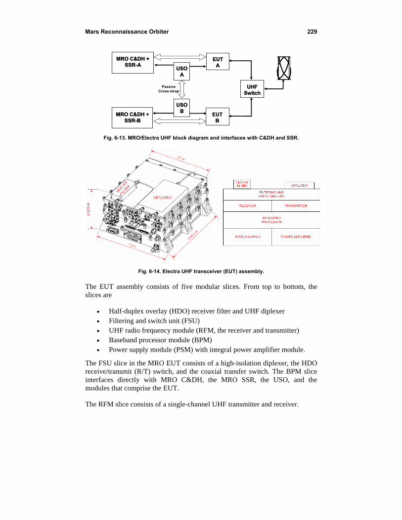
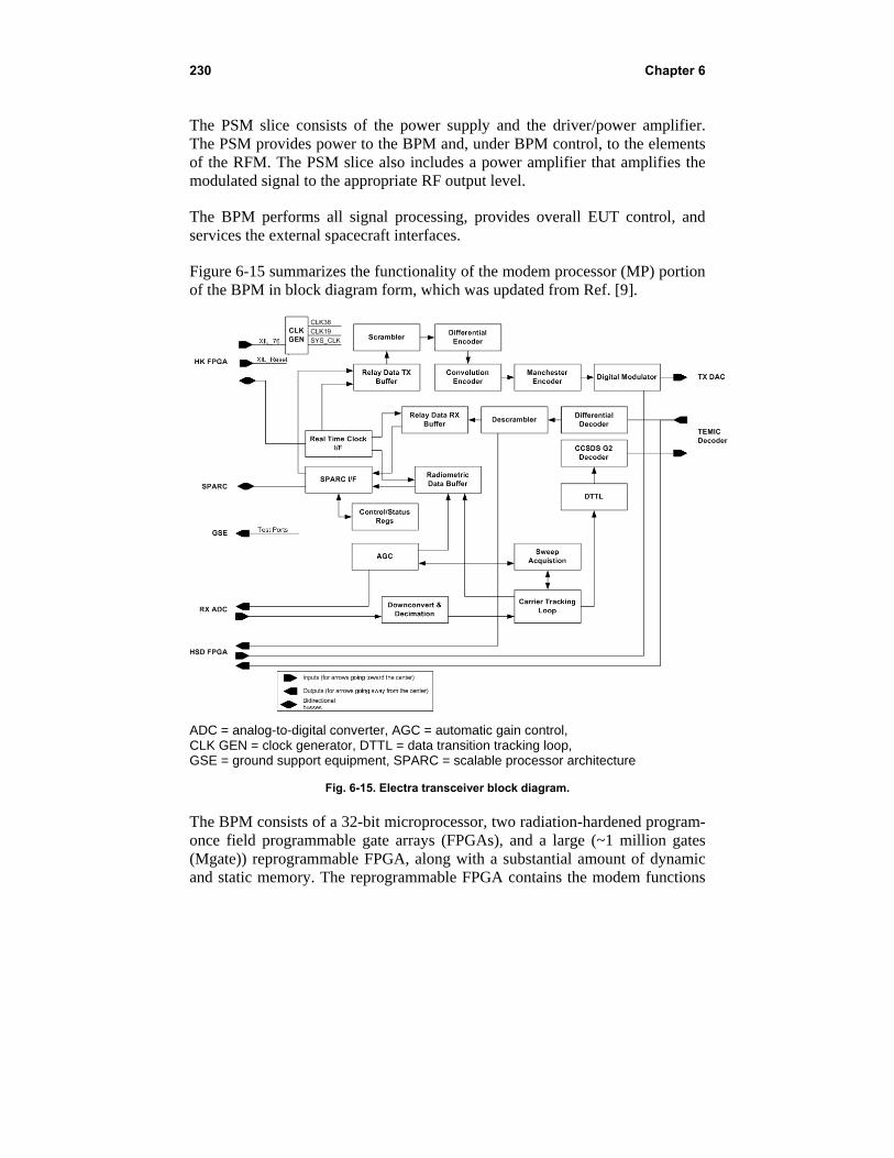
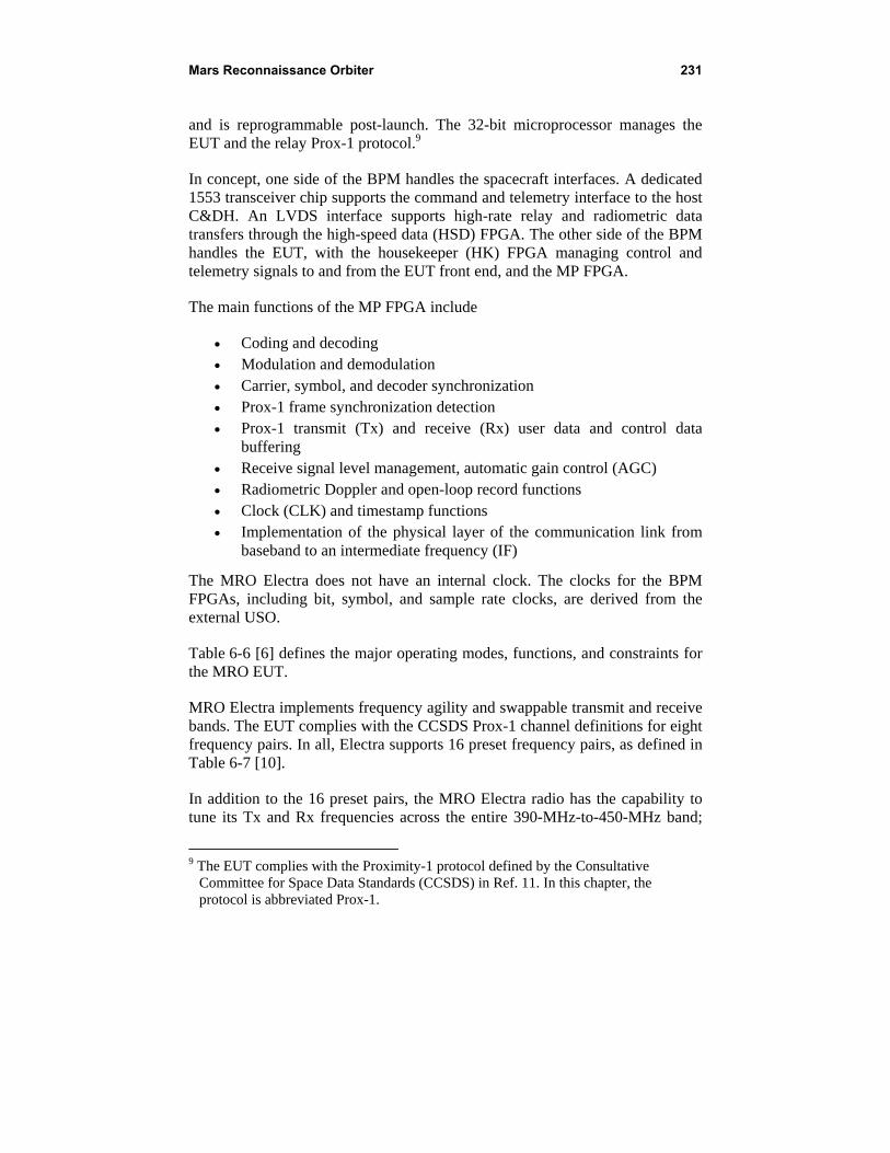
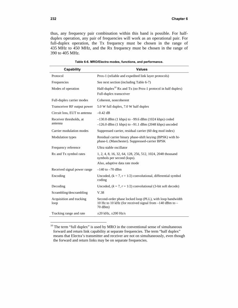
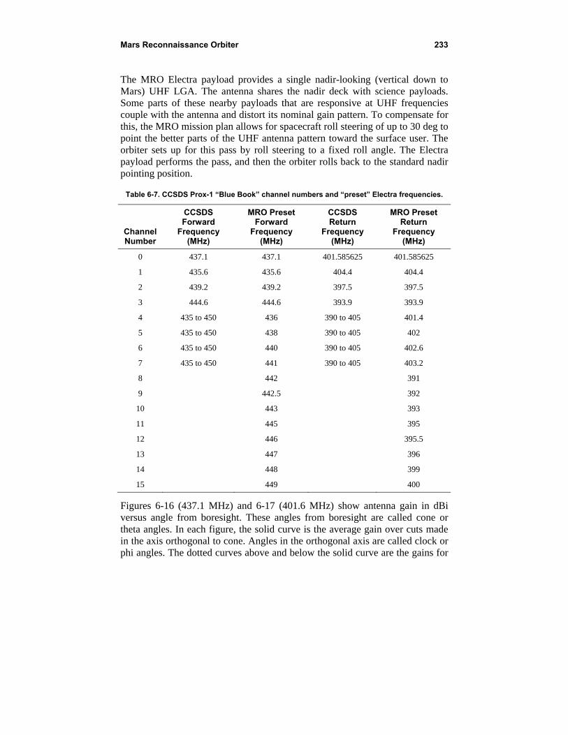
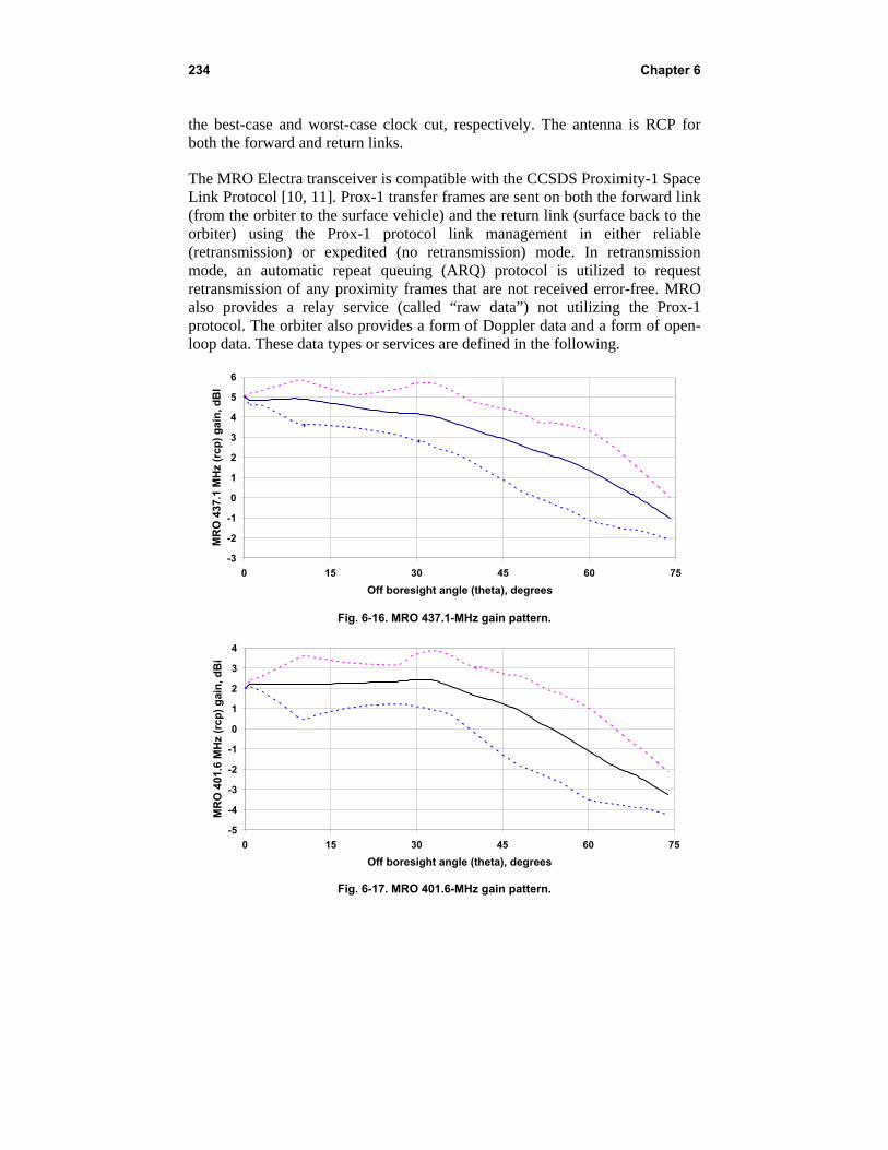
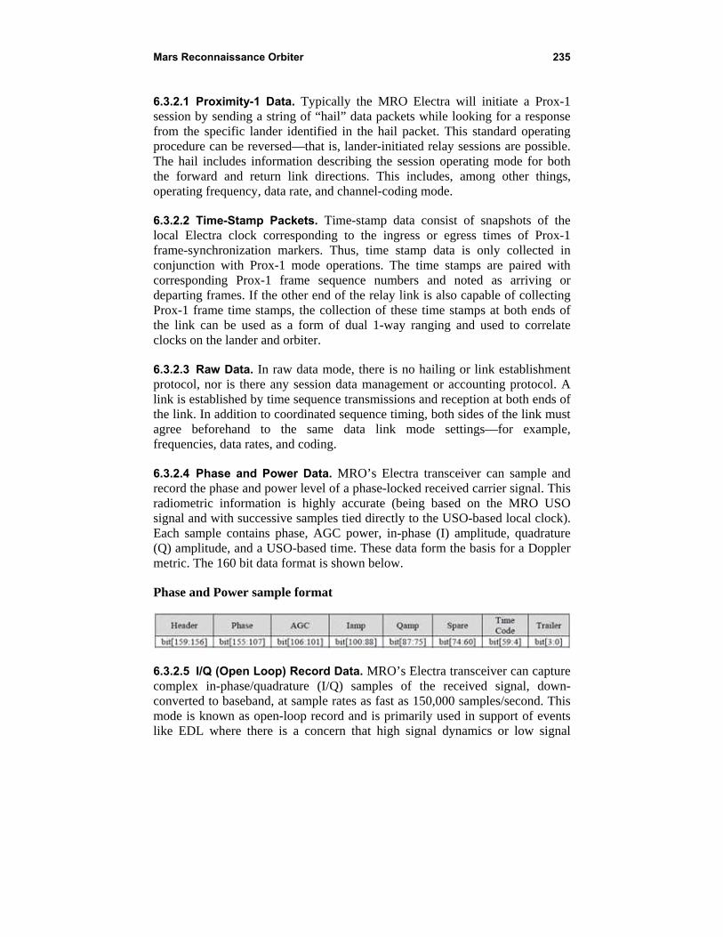
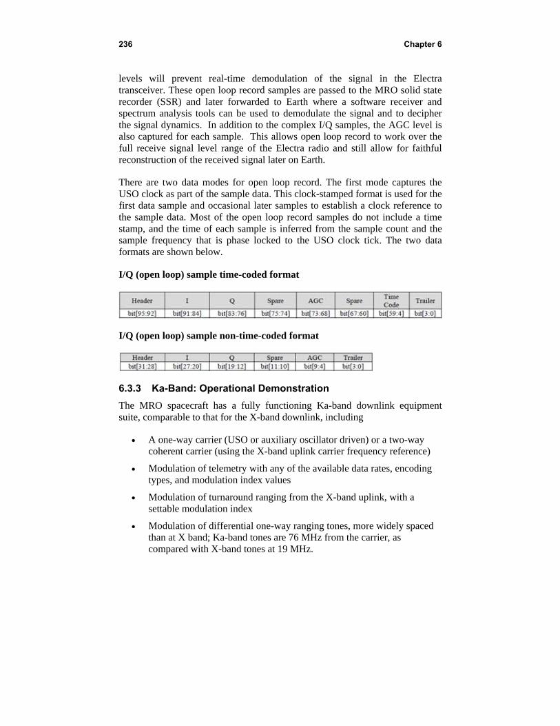
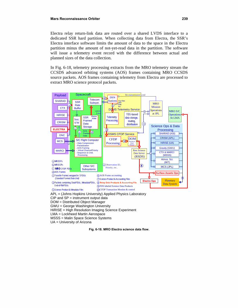
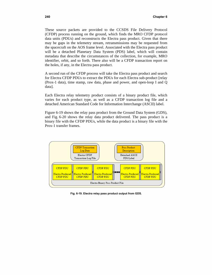
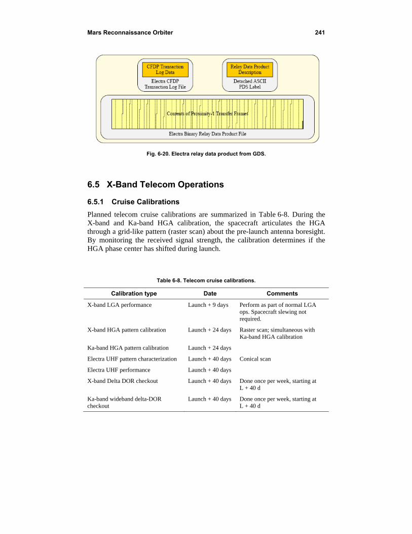
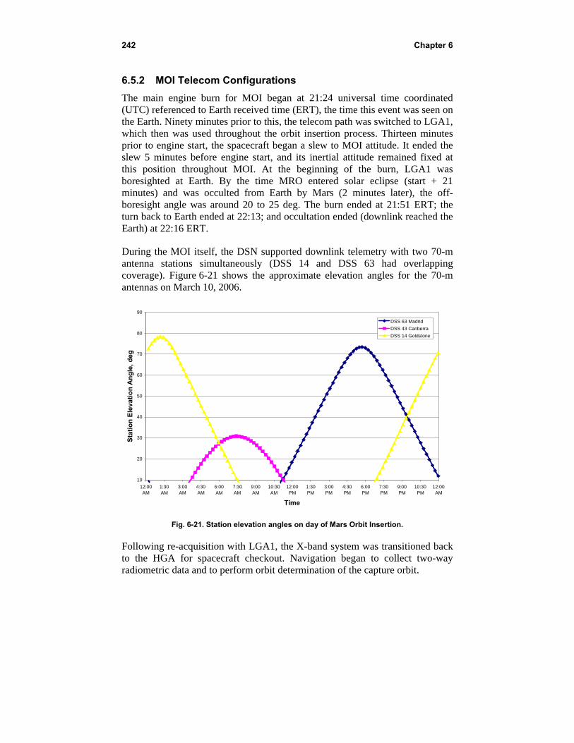
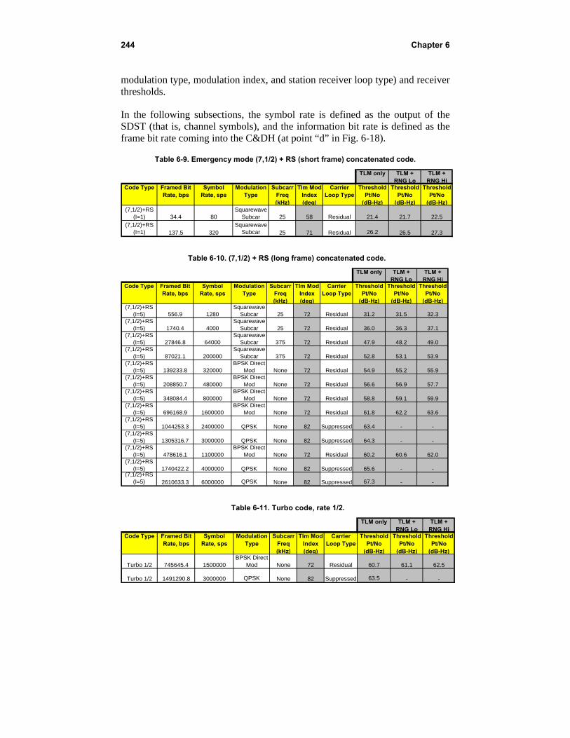
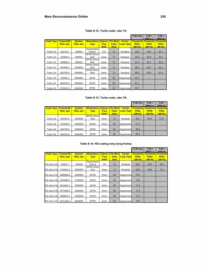
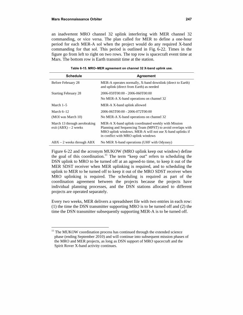
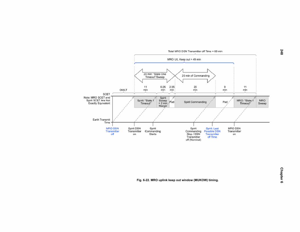
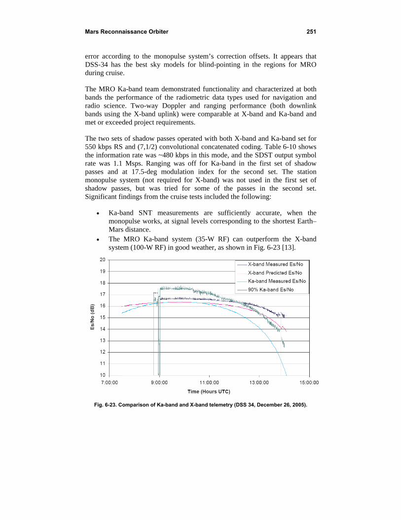
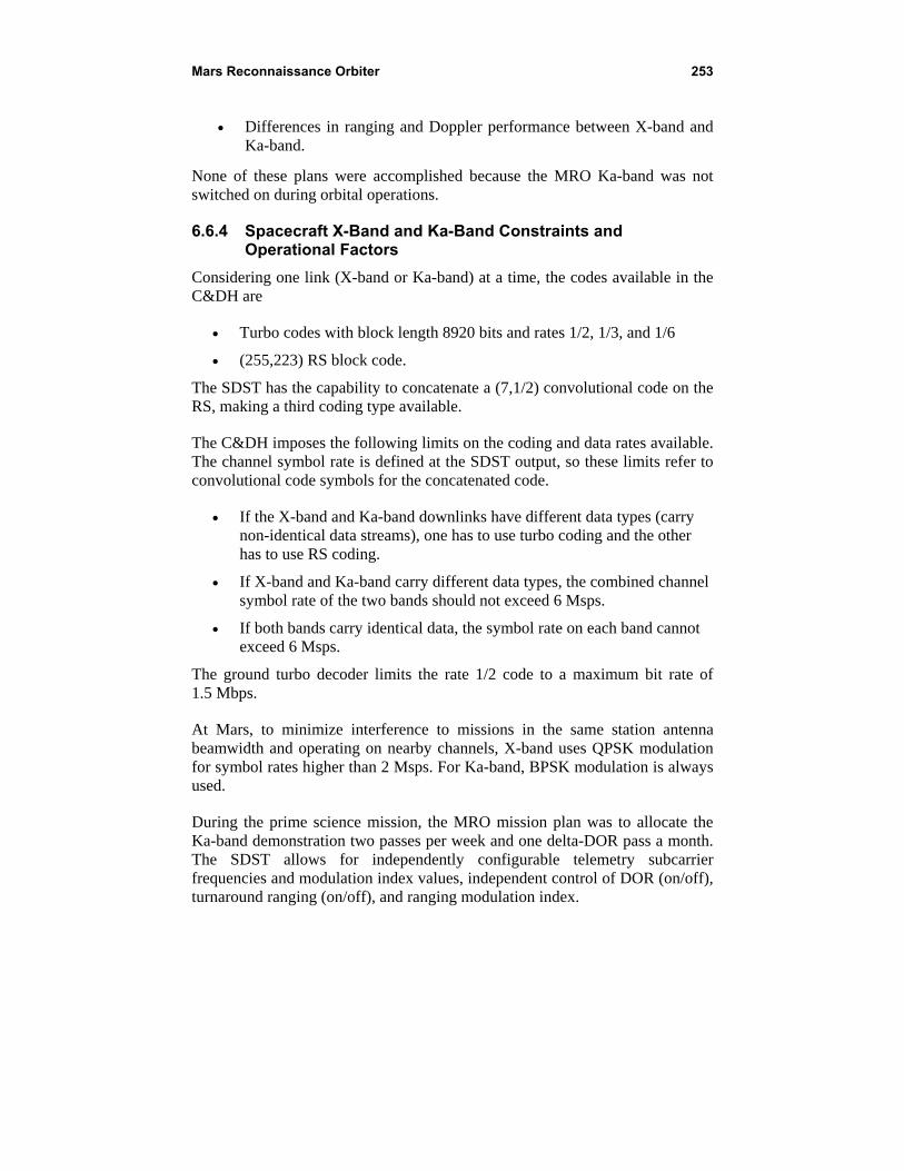

262 Chapter 6