Embed Size (px)
Citation preview
59
Chapter 6 Investigator Equipment Packages This chapter is intended to provide investigators with complete information about structural and electrical guidelines that must be followed as part of the design and construction of research equipment for the GV. While the content of this chapter is intended to be as comprehensive as possible to enable developers to construct fully compliant equipment, investigators should also be aware that EOL personnel can assist investigators with meeting all of the requirements set forth herein for the GV. Contact information for appropriate EOL personnel is provided throughout this chapter in order to facilitate communications between users and EOL staff. Research equipment design should follow the guidance in FAA Advisory Circular 20-168 and RTCA DO-313. These documents standardize and streamline the process for demonstrating compliance with airworthiness requirements for non-Essential, non-required aircraft cabin systems and equipment. Normal operation of the equipment, or failure of it to perform its intended function, cannot adversely affect the safety of the aircraft or its occupants, or the proper functioning of required equipment and systems.
6.1 Structural Considerations This section sets forth the guidelines to be followed for the design, fabrication, and approval of investigator research equipment to be flown onboard the NSF/NCAR GV. The design, modification, and installation of airborne research equipment is one of the more demanding and time consuming aspects of airborne research. Newly designed, commercially purchased, and other equipment not designed for aircraft use must be evaluated for structural integrity and, if necessary, be modified or strengthened to comply with the criteria outlined in this section. Also, all equipment designed for aircraft use will be reviewed for conformity to design and installation specifications. In addition to structural considerations, any wiring in user-supplied equipment must adhere to guidelines established and outlined herein. All equipment must also be designed or modified to attach to the various mounting points and instrument racks on the NSF/NCAR GV. Properly securing all equipment and ensuring that the equipment loads can be reacted to by the aircraft is a mandated requirement to ensure the safety of each crew member and the safe operation of the aircraft. While this requirement is self evident, when combined with the design goal of minimizing weight, it can pose a challenging design problem. A detailed description of the aircraft mounting points and equipment rack capabilities is provided in Chapter 2 of this handbook. Equipment designs that fail to comply with the guidelines of this handbook or hardware that fails to conform to the design documentation will not be installed on the aircraft until the deficiencies are corrected. In the event that the deficiencies cannot be corrected, the equipment will not be permitted on board the aircraft for flight research. RAF Aeronautical Engineering personnel will assist users in understanding and complying with the requirements of this section.
60
6.1.1 Design Criteria Design criteria refers to the general design philosophy that specifies appropriate margins of safety, special analytical factors of safety, and design loads. All equipment and attachment hardware on the NSF/NCAR GV must be substantiated for structural strength by analysis at a minimum. In general, classic hand-stress analysis techniques and calculations are acceptable. However, for systems possessing a high degree of redundancy (multiple load paths), a finite element analysis may be necessary. In the event a finite element analysis is utilized, the internal loads should be extracted from the finite element analysis and hand techniques used to determine the final margins of safety.
6.1.1.1 Margins and Factors In aeronautical design it is customary to compute the margin of safety for particular structural components and attachments. The margin of safety is defined as the ratio of the strength of the member to the applied load multiplied by any factors minus 1, or: MS = (Allowable/(Actual x Factor1 x Factor2 x )) – 1 In lieu of structural tests, a minimum margin of safety of +0.20 in the analysis must be maintained for flight and landing conditions. Emergency landing load conditions are excluded from this “no-test” margin of safety requirement and need show only a positive margin of safety (+0.00). Equipment and attachments substantiated by test also require a minimum analytical margin of safety of +0.00. In addition to the margin of safety requirement, additional factors are applicable for analysis of research equipment and installations. These additional factors are given in Table 6.1 and it should be noted that multiple factors might apply.
Type Application Symbol Value
Factor of Safety
Applied to limit loads F.S. 1.50
Aerodynamic Load Factor
Applied to aerodynamic loads not verified by wind tunnel testing when evaluating primary structure.(1)
Caero 1.25
Equipment Mass Factor
Applied to black box mass to account for structural, wire bundle, and any other miscellaneous mass.(2)
Cmass 1.25
Fitting Factor, General
Applied to Margin of Safety equation for structural joint evaluations not verified by test and applicable to all conditions.
F.F. 1.15
Fitting Factor, Quick Change Items
Applied to Margin of Safety equation for the attachment of frequently installed/ removed fixed equipment.
F.F. 1.33
61
Table 6.1: Analytical Factors
Note 1: The aerodynamic load factor is not used for load conditions where air loads are relieving. When aerodynamic loads are relieving, either ignore the air loads entirely (most conservative) or use a factor of 1.0 if air loads are known to exist for the given flight condition. Note 2: This factor accounts for inaccuracies between the actual and assumed center of gravity location, which is assumed to be at the approximate geometric center of the equipment. Additional bearing and/or casting factors may also be applicable depending on the design. Investigators should contact RAF Aeronautical Engineering for additional factor values if required.
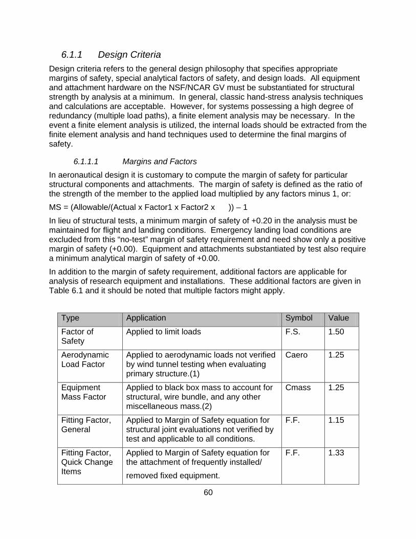
6.1.1.2 Loads Equipment installed on aircraft is subject to a variety of loading conditions. These loads can be the result of emergency landing, inertia loading (maneuvering, gust, normal landing), handling loads, pressurization, and aerodynamic lift and drag. All equipment must be analyzed for the required and expected loading conditions and must show a positive margin of safety as described previously. Emergency landing loads are defined as loading that occurs during other than a normal landing, such as a wheels-up landing or veering off the runway. All equipment (including racks, instruments, pallets, tie-downs, etc.) and supporting structure that attaches to the aircraft in an occupied area (cockpit, cabin) that could cause injury to an occupant if it broke loose must be restrained for the emergency landing conditions listed in Table 6.2. The emergency landing condition loads act separately and are ultimate loads. These loads act independent of the flight loads and pressurization loads.
Direction Emergency Landing Load Factor (Ultimate)
Up (Normal to Airplane Longitudinal Axis) 3.0g
Forward (Parallel to Airplane Longitudinal Axis) 9.0g
Sideward (Normal to Airplane Symmetry Plane) ±3.0g (Airframe) ±4.0g (Seats & Seat Attachments)
Downward (Normal to Airplane Longitudinal Axis) 6.0g
Rearward (Parallel to Airplane Longitudinal Axis) 1.5g
Table 6.2: 14 CFR Part 25, Emergency Landing Load Factors
62
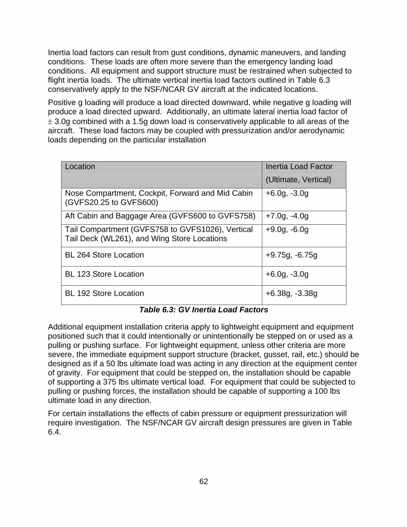
Inertia load factors can result from gust conditions, dynamic maneuvers, and landing conditions. These loads are often more severe than the emergency landing load conditions. All equipment and support structure must be restrained when subjected to flight inertia loads. The ultimate vertical inertia load factors outlined in Table 6.3 conservatively apply to the NSF/NCAR GV aircraft at the indicated locations. Positive g loading will produce a load directed downward, while negative g loading will produce a load directed upward. Additionally, an ultimate lateral inertia load factor of ± 3.0g combined with a 1.5g down load is conservatively applicable to all areas of the aircraft. These load factors may be coupled with pressurization and/or aerodynamic loads depending on the particular installation
Location Inertia Load Factor (Ultimate, Vertical)
Nose Compartment, Cockpit, Forward and Mid Cabin (GVFS20.25 to GVFS600)
+6.0g, -3.0g
Aft Cabin and Baggage Area (GVFS600 to GVFS758) +7.0g, -4.0g
Tail Compartment (GVFS758 to GVFS1026), Vertical Tail Deck (WL261), and Wing Store Locations
+9.0g, -6.0g
BL 264 Store Location +9.75g, -6.75g
BL 123 Store Location +6.0g, -3.0g
BL 192 Store Location +6.38g, -3.38g
Table 6.3: GV Inertia Load Factors
Additional equipment installation criteria apply to lightweight equipment and equipment positioned such that it could intentionally or unintentionally be stepped on or used as a pulling or pushing surface. For lightweight equipment, unless other criteria are more severe, the immediate equipment support structure (bracket, gusset, rail, etc.) should be designed as if a 50 lbs ultimate load was acting in any direction at the equipment center of gravity. For equipment that could be stepped on, the installation should be capable of supporting a 375 lbs ultimate vertical load. For equipment that could be subjected to pulling or pushing forces, the installation should be capable of supporting a 100 lbs ultimate load in any direction. For certain installations the effects of cabin pressure or equipment pressurization will require investigation. The NSF/NCAR GV aircraft design pressures are given in Table 6.4.
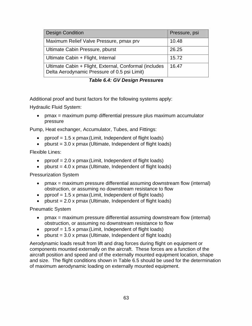
63
Design Condition Pressure, psi
Maximum Relief Valve Pressure, pmax prv 10.48
Ultimate Cabin Pressure, pburst 26.25
Ultimate Cabin + Flight, Internal 15.72
Ultimate Cabin + Flight, External, Conformal (includes Delta Aerodynamic Pressure of 0.5 psi Limit)
16.47
Table 6.4: GV Design Pressures
Additional proof and burst factors for the following systems apply: Hydraulic Fluid System:
• pmax = maximum pump differential pressure plus maximum accumulator pressure
Pump, Heat exchanger, Accumulator, Tubes, and Fittings:
• pproof = 1.5 x pmax (Limit, Independent of flight loads) • pburst = 3.0 x pmax (Ultimate, Independent of flight loads)
Flexible Lines:
• pproof = 2.0 x pmax (Limit, Independent of flight loads) • pburst = 4.0 x pmax (Ultimate, Independent of flight loads)
Pressurization System
• pmax = maximum pressure differential assuming downstream flow (internal) obstruction, or assuming no downstream resistance to flow
• pproof = 1.5 x pmax (Limit, Independent of flight loads) • pburst = 2.0 x pmax (Ultimate, Independent of flight loads)
Pneumatic System
• pmax = maximum pressure differential assuming downstream flow (internal) obstruction, or assuming no downstream resistance to flow
• pproof = 1.5 x pmax (Limit, Independent of flight loads) • pburst = 3.0 x pmax (Ultimate, Independent of flight loads)
Aerodynamic loads result from lift and drag forces during flight on equipment or components mounted externally on the aircraft. These forces are a function of the aircraft position and speed and of the externally mounted equipment location, shape and size. The flight conditions shown in Table 6.5 should be used for the determination of maximum aerodynamic loading on externally mounted equipment.
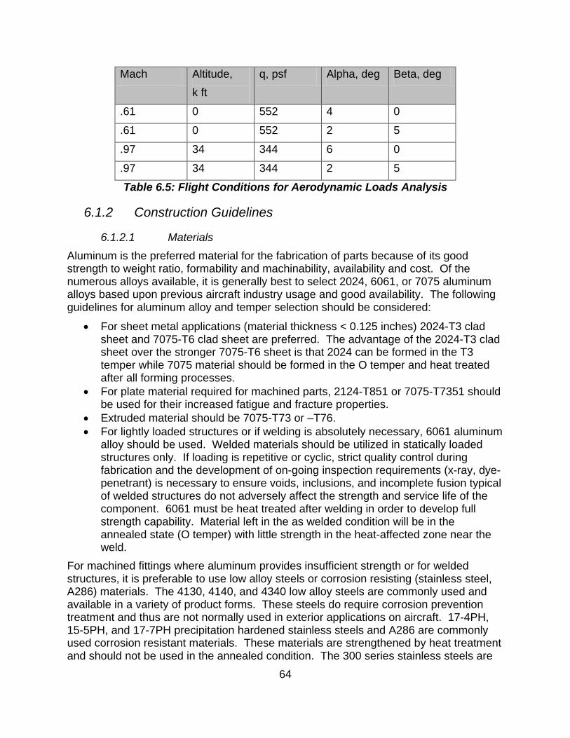
64
Mach Altitude, k ft
q, psf Alpha, deg Beta, deg
.61 0 552 4 0
.61 0 552 2 5
.97 34 344 6 0
.97 34 344 2 5
Table 6.5: Flight Conditions for Aerodynamic Loads Analysis
6.1.2 Construction Guidelines
6.1.2.1 Materials Aluminum is the preferred material for the fabrication of parts because of its good strength to weight ratio, formability and machinability, availability and cost. Of the numerous alloys available, it is generally best to select 2024, 6061, or 7075 aluminum alloys based upon previous aircraft industry usage and good availability. The following guidelines for aluminum alloy and temper selection should be considered:
• For sheet metal applications (material thickness < 0.125 inches) 2024-T3 clad sheet and 7075-T6 clad sheet are preferred. The advantage of the 2024-T3 clad sheet over the stronger 7075-T6 sheet is that 2024 can be formed in the T3 temper while 7075 material should be formed in the O temper and heat treated after all forming processes.
• For plate material required for machined parts, 2124-T851 or 7075-T7351 should be used for their increased fatigue and fracture properties.
• Extruded material should be 7075-T73 or –T76. • For lightly loaded structures or if welding is absolutely necessary, 6061 aluminum
alloy should be used. Welded materials should be utilized in statically loaded structures only. If loading is repetitive or cyclic, strict quality control during fabrication and the development of on-going inspection requirements (x-ray, dye-penetrant) is necessary to ensure voids, inclusions, and incomplete fusion typical of welded structures do not adversely affect the strength and service life of the component. 6061 must be heat treated after welding in order to develop full strength capability. Material left in the as welded condition will be in the annealed state (O temper) with little strength in the heat-affected zone near the weld.
For machined fittings where aluminum provides insufficient strength or for welded structures, it is preferable to use low alloy steels or corrosion resisting (stainless steel, A286) materials. The 4130, 4140, and 4340 low alloy steels are commonly used and available in a variety of product forms. These steels do require corrosion prevention treatment and thus are not normally used in exterior applications on aircraft. 17-4PH, 15-5PH, and 17-7PH precipitation hardened stainless steels and A286 are commonly used corrosion resistant materials. These materials are strengthened by heat treatment and should not be used in the annealed condition. The 300 series stainless steels are
65
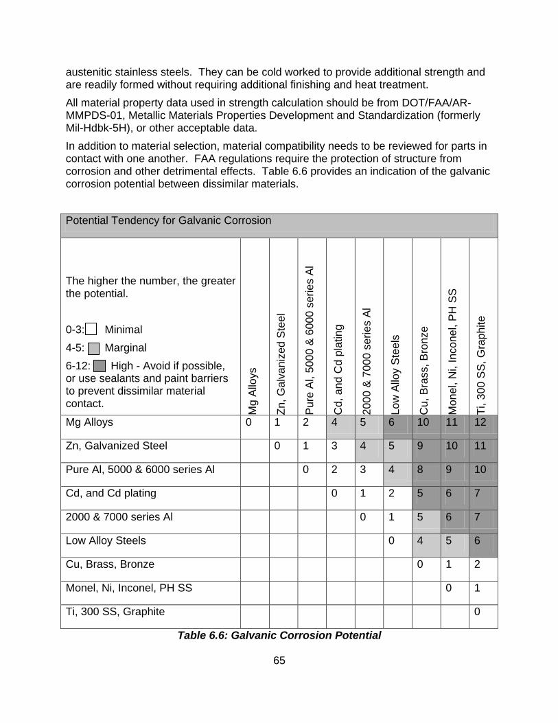
austenitic stainless steels. They can be cold worked to provide additional strength and are readily formed without requiring additional finishing and heat treatment. All material property data used in strength calculation should be from DOT/FAA/AR-MMPDS-01, Metallic Materials Properties Development and Standardization (formerly Mil-Hdbk-5H), or other acceptable data. In addition to material selection, material compatibility needs to be reviewed for parts in contact with one another. FAA regulations require the protection of structure from corrosion and other detrimental effects. Table 6.6 provides an indication of the galvanic corrosion potential between dissimilar materials.
Potential Tendency for Galvanic Corrosion
The higher the number, the greater the potential. 0-3: Minimal 4-5: Marginal 6-12: High - Avoid if possible, or use sealants and paint barriers to prevent dissimilar material contact.
Mg
Allo
ys
Zn, G
alva
nize
d St
eel
Pure
Al,
5000
& 6
000
serie
s Al
Cd,
and
Cd
plat
ing
2000
& 7
000
serie
s Al
Low
Allo
y St
eels
Cu,
Bra
ss, B
ronz
e
Mon
el, N
i, In
cone
l, PH
SS
Ti, 3
00 S
S, G
raph
ite
Mg Alloys 0 1 2 4 5 6 10 11 12
Zn, Galvanized Steel 0 1 3 4 5 9 10 11
Pure Al, 5000 & 6000 series Al 0 2 3 4 8 9 10
Cd, and Cd plating 0 1 2 5 6 7
2000 & 7000 series Al 0 1 5 6 7
Low Alloy Steels 0 4 5 6
Cu, Brass, Bronze 0 1 2
Monel, Ni, Inconel, PH SS 0 1
Ti, 300 SS, Graphite 0
Table 6.6: Galvanic Corrosion Potential
66
6.1.2.2 Fasteners All fasteners should be aircraft quality hardware (to AN, MS, or NAS standards and specifications). Table 6.7 provides information on more commonly used aircraft fasteners.
Designation Fastener Description
Conventional Rivets MS20470AD MS20426AD NAS1097
Protruding Head Solid Rivet Flush, Full Size Head Flush, Reduced Head
HI-Loks HL18 HL19 HL70 HL20 HL21 HL86
Protruding Shear Head Pin Flush Shear Head Pin Shear Collar Protruding Tension Head Pin Flush Tension Head Pin Tension Collar
Bolts/Screws AN3-AN20 NAS6203-NAS6220 MS24694 NAS517 AN525 MS27039 NAS623
Hex Head Bolt (125 ksi) Hex Head Bolt (160 ksi) Flush Head, Phillips Drive (125 ksi) Flush Head, Phillips Drive (160 ksi) Washer Head, Phillips Drive Screw Pan Head, Phillips Drive (125 ksi) Pan Head, Phillips Drive (160 ksi)
Washers NAS1149 AN970
Plain Washer Large Area Flat Washer
Nuts MS21042 MS21044 NAS1804
Hex Nut, Low Height, Self Lock (160 ksi tension) Hex Head, Full Height, Nylon Lock (125 ksi tension) 12 point, Full height (180 ksi tension)
67
MS21059 MS21075 MS21061 NAS1473 NAS1474
Floating Nutplate, Std Spacing Floating Nutplate, Mini Spacing Floating Nutplate, Std Spacing, One Lug Self Sealing Nutplate, Std Spacing Self Sealing Nutplate, Mini Spacing
Inserts MS21209 MS51830 MS51831 MS51832
Locking Helical Coil Wire Screw Thread, Key Locked, Regular Duty (Keensert) Screw Thread, Key Locked, Heavy Duty (Keensert) Screw Thread, Key Locked, Extra Heavy Duty (Keensert)
Blind Fasteners NAS1669 NAS1670 M7885/2 M7885/3 M7885/13
Hex Head Blind Bolt (Jo-Bolt) Flush Head Blind Bolt (Jo-Bolt) Protruding Head Blind Rivet (Cherry-Max CR3213)) Flush Head Blind Rivet (Cherry Max CR3212) Flush Shear Head Blind Rivet
Table 6.7: Aircraft-Quality Fasteners
6.1.2.3 Welding While bolting and/or riveting are the preferred methods of assembly, welding may be required in some special situations. The following guidelines should be observed for welded structures:
• Materials should be suitable for welding (see material section above). • Welded structures must be heat treated in order to develop full strength. • Welding should only be done by currently certified personnel.
6.1.2.4 Lines and Fittings Lines and fittings for hydraulic and pneumatic systems should be aircraft quality and appropriately rated for the expected operating service loads and the required test loads given in Section 6.1.1.2 above.
6.1.3 Installation
6.1.3.1 Main Cabin Equipment Racks and other cabin installations The majority of equipment in the cabin will be mounted in standard racks designed by NCAR that attach to the floor and ceiling tracks in the GV aircraft. The racks are
68
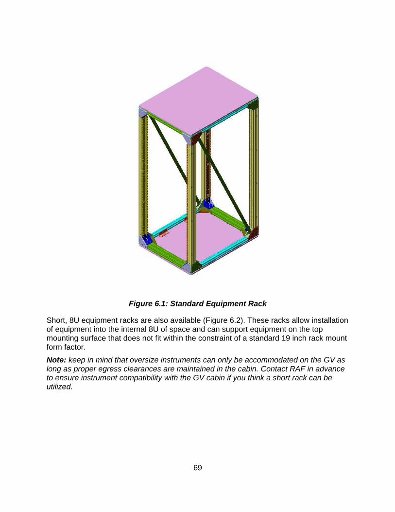
designed to accept standard 19 inch wide rack mountable equipment. Mounting rails conforming to the universal spacing of EIA Standard RS-310 are provided on each side of the rack both forward and aft facing. The racks are 50 inches high, 21.5 inches wide and 28 inches deep. There are 24U (42 inch) mounting rails on the forward and aft faces for standard 19 inch rack mountable equipment. The mounting rails are symmetrically centered vertically on the rack. The mounting faces of the rails are flush with the forward and aft faces of the rack. The panel mounting rails enable equipment to be face mounted on the forward or aft rack face, rail, or plate mounted at each vertical frame member. The particular mounting option will be determined by the equipment weight and mass properties. A 3/8 inch panel is attached to the top and bottom and can also be used for equipment mounting. These aluminum honeycomb panels require inserts to enable equipment mounting. There is 3.6 inches of clearance between the ends of the mounting rails and the inner surfaces of the panels. The bottom plate of the MCE rack can be bear equipment by modifying it to install potted threaded inserts. This type of installation is highly recommended for heavy components such as pumps. Equipment attached to the bottom plate has a zero inch CG height in the rack and does not contribute to the overturning moment (although it does contribute to the total weight, which is limited by the maximum GV floor loading). The upper MCE rack plate can be removed to allow limited protrusion of components from the rack internal space. Upper plates should be installed on all racks that do not have such protruding parts, for equipment protection. Figure 6.1 shows a standard cabin equipment rack. The maximum allowable equipment weight is 350 lbs. The maximum allowable equipment overturning moment (measured from the bottom of the lower panel, i.e., the base of the rack) is 7,000 inch-lbs. Researchers should prepare a scaled layout of their rack configuration and determine:
• Individual component weight; • Individual component panel height; • Individual component center of gravity (cg) distance from panel; • Total equipment weight (S component weights); and • Total moment (S component weight x cg height from base).
A rack attached to the floor seat track and ceiling rail (not available at all floor stations, contact RAF for more information) can support 340 lbs of equipment with the CG located at 25 inches above floor level (8,400 in-lbs overturning moment). RAF has designs and actual parts for additional hardware for rackmount installations. Full length and half length aluminum shelves are available with a 70 lbs and 20 lbs load capacity, respectively. Laptop mounting trays and storage drawers are also available.
69
Figure 6.1: Standard Equipment Rack
Short, 8U equipment racks are also available (Figure 6.2). These racks allow installation of equipment into the internal 8U of space and can support equipment on the top mounting surface that does not fit within the constraint of a standard 19 inch rack mount form factor. Note: keep in mind that oversize instruments can only be accommodated on the GV as long as proper egress clearances are maintained in the cabin. Contact RAF in advance to ensure instrument compatibility with the GV cabin if you think a short rack can be utilized.
70
Figure 6.2: Short (8U) equipment rack drawing. A full size MCE rack is shown in
gray scale for comparison. All dimensions in inches.
For installation of large optical instruments in the proximity of the optical viewports in the forward cabin there exists a design for a longer, half height rack that can accommodate a large instrument on the top, more equipment in the rack and spans two floor stations L1 and L2. The existing rack is instrument specific and cannot be used for other installations, however the design is approved and certified can be replicated if necessary. This design also includes a cantilever mounting for a telescope aligned with the forward coaxial viewports. To expedite the project upload process, all racks should be flight ready (equipment and instrumentation installed and power/communications ground checked) prior to installation on the aircraft. Failure to do so may lengthen the installation and approval process and could impact the project start date. Racks can be obtained from EOL in advance for pre-deployment build-up by contacting the appropriate RAF Project Manager. As an alternative, users expecting to fly on the GV frequently may wish to purchase a rack from NCAR or fabricate a standard rack from NCAR-provided drawings and specifications. The NCAR/EOL Design and Fabrication Services (DFS) Manager can provide additional information on these latter two options. Face mounted equipment weight and moment (weight x center of gravity distance from the mounting panel) must fall below the maximum allowable curves given in Figure 6.3. For example, equipment weighing 75 lbs would require a 2U (3.75 inch) panel for forward face mounting or a 3U (5.25 inch) panel for aft face mounting. Per Figure 6.3, equipment weighing 50 lbs and 8 inches deep (center of gravity = 8 / 2 = 4 inches from the mounting panel) would produce a moment at the face of 200 inch-lbs (Moment = 50 x 4 = 200 inch-lbs) and would require a 3U (5.25 inch) mounting panel height minimum.
71
For equipment that falls above these allowable curves, additional internal support and bracing (longitudinal mounting rails or trays) will be required. Two types of trays for supporting non-rack mountable and/or heavy equipment are available. Aeronautical Engineering can assist the researcher in determining the proper support requirements.
Figure 6.3: Allowable equipment weight for mounting to face chart
Modifications to standard equipment racks are not permitted under any circumstances. Stress analysis of the rack structure, track attachments, and floor structure is not required, except for nonstandard installations. User-supplied racks and other nonstandard installations (optical benches, etc.), will require stress analysis of the support structure, equipment attachment locations, and floor/ceiling attachments. Due to the level of effort required to approve special racks, early coordination with RAF Aeronautical Engineering is necessary. Maximum equipment weight for the cabin floor cannot exceed any of the following parameters:
• 49 lbs per square foot uniformly distributed, • 98 lbs per square foot with a 20 inch central clear aisle, or • 200 lbs per square foot (187 lbs per square foot on the center aisle) applied to
one isolated square foot at least 30 inches from another load.
0
50
100
150
200
250
300
350
0 1.75 3.5 5.25 7 8.75 10.5 12.25 14
Panel Height, in
Equi
pmen
t Wei
ght,
lbs
FwdAft
72
Figure 6.4: Allowable face-mounted equipment moment chart
6.1.3.2 Non-Personnel Occupied Compartments There is limited room in the nose area, baggage compartment, and tail deck for equipment installations. Equipment in the nose area and the tail deck will be secured to shelves that are attached to structure in this region. Contact the RAF Aeronautical Engineering group for interface and capability information. A floor to ceiling open rack standard type per EIA Standard RS-310 will be available. The allowable equipment weight for the rack in the baggage area is 150 lbs with a maximum moment at the floor of 4,200 inch-lbs.
6.1.3.3 Wing Stores Refer to Section 5.1.5 above for the overview of available wing store configurations.
6.1.3.4 Fuselage Exterior The numerous fuselage pads, hardpoints, and apertures were described in Chapter 2 of this handbook. Table 6.8 presents the structural capabilities for the various locations.
0
100
200
300
400
500
600
700
800
900
1000
0 1.75 3.5 5.25 7 8.75 10.5 12.25
Panel Height, in
Equi
pmen
t Mom
ent,
in-lb
s
73
Location Static Load, lbs
Frontal Area, sq. in., Or Envelope, L in. x W in. x H in.
CG from A/C Skin, inches
Forward Fuselage Pad 2 18 9
Center Fuselage Mounts 25 24 20
Apertures External Equipment Internal Eqt, Upper Internal Eqt, Lower
50 25 25
54 16 x 16 x 8 13.5 x 10.5 x 9.5 inbd, 7.5 outbd
12 8 16
GVFS290.5 Optical Ports 90 NA
GVFS339.5 Optical Port Optical Insert External Equipment
90 36
NA 65
10
Table 6.8: External Mounting Provision Capabilities
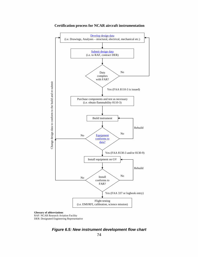
6.1.4 Certification The instrument provider is responsible for ensuring that their equipment package meets the design criteria of this handbook. Failure to follow these guidelines may require rework of research equipment packages that may affect project cost and schedule. Equipment that cannot be approved for flight research will not be permitted onboard the aircraft. Following the new instrument development flowchart shown on Figure 6.5 will help ensure that the design process is tied with the necessary certification steps and minimize the wasted effort.
74
Figure 6.5: New instrument development flow chart
Certification process for NCAR aircraft instrumentation
Submit design data (i.e. to RAF, contract DER)
Build instrument
Flight testing (i.e. EMI/RFI, calibration, science mission)
Install equipment on GV
Purchase components and test as necessary (i.e. obtain flammability 8110-3)
Data complies
with FAR?
Equipment conforms to
data?
Install conforms to
FAR?
Develop design data (i.e. Drawings, Analyses – structural, electrical, mechanical etc.)
Yes (FAA 8110-3 is issued)
No
Yes (FAA 337 or logbook entry)
No
Yes (FAA 8130-3 and/or 8130-9)
No
No
No
Rebuild
Rebuild
Cha
nge
desi
gn d
ata
to c
onfo
rm to
the
build
and
re-s
ubm
it
Glossary of abbreviations RAF: NCAR Research Aviation Facility DER: Designated Engineering Representative
75
RAF will be responsible for the final approval and/or certification of all aircraft modifications and equipment installations. It is expected that the majority of research equipment will be considered miscellaneous, non-required electrical equipment per FAA Advisory Circular AC25-10. This finding will simplify the approval process for installations while maintaining an appropriate level of safety. In order to accomplish the approval/certification process, the RAF will require the following data package from the research scientist for each equipment installation:
6.1.4.1 Descriptive Data Component, assembly, and installation drawings are preferred. However, with cost and schedule constraints, marked up photographs, sketches, written descriptions, marked-up excerpts from manufacturers’ parts catalogs, or similar document excerpts are acceptable. The data must be sufficient to completely describe the individual equipment components and complete assembly/installation. The data will generally include dimensional geometry, weight and balance information, materials, fasteners used and attachment location, vendor data for off the shelf items, ratings and power requirements, etc. Scaled and dimensioned layouts of equipment mounted in standard racks, with weight and moment information will be required. Any special processes or specifications used in the fabrication of the research equipment package should also be described.
6.1.4.2 Substantiating Data The substantiating data package will be comprised of analyses and test plans and reports if necessary. The basic load conditions for the GV and allowable material strength data have been previously discussed in this handbook. Thus, a structural analysis and electrical loads analysis is generally all that is required. The researcher should ensure that the analytical methods and assumptions are appropriate, that all applicable loading conditions are checked, and that sufficient margin of safety exists for all structural elements and electrical components. RAF Aeronautical Engineering can usually assist the researcher with the structural analysis report depending on workload. RAF’s Electrical and Instrumentation Group can assist with the electrical loads analysis, again depending on workload. Early coordination and planning will be required in order to determine the appropriate level of effort for both the research and the RAF staff so project schedules are not adversely affected. For typical equipment packages, all data should be submitted to the RAF prior to the start of fabrication in order to reduce the risk of rework being required. Additionally, all required data must be provided to the RAF at least eight weeks prior to the start of equipment installation on the aircraft. A longer lead time may be required for complex or unusual installations. Additional review will be required for the following hazardous equipment/materials:
• Lasers • RF Emitters • Cryogens (oxygen, hydrogen, methane, ethane, and ethylene prohibited) • Compressed Gases
76
• Toxic Gases (may require containment) • Batteries • Pressure Vessels/Systems • Motors/Pumps (except for small fan units in commercial electronic equipment –
400 Hz motors rated explosion proof or totally enclosed non-ventilated are preferred; DC brush-type motors are generally not acceptable)
• Heaters (surfaces >130oF require shielding and labeling) • Power Distribution Equipment • Radioactive Materials • Flammable/Noxious Materials (PVC jacketed wire [except in commercial units]
and cable or plumbing is not acceptable - Teflon based materials should be used; consult RAF Safety Committee concerning material acceptability)
Researchers should prepare and submit safety documentation and coordinate with the RAF Project Management to ensure that appropriate approvals are obtained prior to the start of operations.
6.2 Electrical Considerations The following sections provide guidance to investigators for the electrical design of equipment intended for flight on board the NSF/NCAR GV. Electrical components within a research system can be the source of potentially hazardous situations in flight, the latter of which can include interference with basic aircraft systems, fire, shock, etc. Correspondingly, care must be taken during the equipment selection and wiring processes in order to minimize these risks.
6.2.1 Materials Selection and Testing Because the GV will be maintained and operated as a certified civil aircraft, all wiring insulation used in investigator equipment packages must comply with Federal Aviation Regulations (FAR) Part 25.869(a) (4), Fire Protection: Systems. This regulation requires insulation on electrical wire and electrical cable to be self-extinguishing when tested in accordance with Part I of Appendix F of FAR Part 25. Investigators can view the FARs (which are contained in Title 14 – Aeronautics and Space – of the Code of Federal Regulations [CFR]) on-line at http://ecfr.gpoaccess.gov. RAF personnel will assist investigators in complying with regulatory requirements. However, it should be noted that the investigator is ultimately responsible for providing the proper documentation as to the type of wire that has been used in the equipment package and verification that the wire meets the requirements outlined above. The RAF will stock some wire and cable in-house that has passed the requisite flammability testing. Small quantities of approved wiring from RAF stock can be provided to investigators under special circumstances. However, investigators should not assume that the RAF will provide the wiring needed for all user equipment needs. Below, guidelines for compliance with applicable FAA requirements are given, and it is the responsibility of investigators and instrument builders to follow these guidelines in order to ensure that approved wiring is used in equipment to be deployed on the GV. Investigators are also strongly encouraged to contact the Certification Engineer of the
77
RAF Engineering and Instrumentation group early in the instrumentation design/project payload configuration process for assistance in interpreting and complying with these requirements. The following wire types meet FAA requirements and can be used on the GV:
• Wiring specifically listed in FAA Advisory Circular 43.13-1B, Table 11-11 (Open Wiring) and Table 11-12 (Protected Wiring). A copy of FAA Advisory Circular 43.13-1B can be downloaded at http://www.faa.gov/certification/aircraft/av-info/dst/43-13/default.htm.
• Wiring for which an existing FAA Form 8110-3 can be supplied. This form – when signed by a qualified person (i.e., a FAA Designated Engineering Representative, or DER) – is used to document that the wire/cabling in question meets the requirements of FAR Part 25.869(a) (4).
• Wiring from the approved wire list provided in Appendix C or from the updated List of Approved Wire and Materials on the RAF web site: http://www.eol.ucar.edu/instrumentation/aircraft/G-V/documentation/approved-wire.
The following wire types are exempt from the testing requirements outlined above and can be used on the GV:
• Wiring installed within commercial off the shelf (COTS) equipment chassis, computers, monitors, etc. Commercial power strips are the exception and are not acceptable, unless they have been modified to incorporate an aircraft approved circuit breaker and aircraft approved wire.
• Wiring provided by a manufacturer to interconnect two or more COTS units (i.e. keyboard and mouse wires, monitor cables, etc.).
Instrument builders must demonstrate that all user-fabricated interconnecting wire (e.g., from component to component, component to aircraft interface, etc.) complies with the requisite FAA requirements. Wire and cable types referred to here include any special types of wire, such as high-speed data wire, fiber optic cable, coax cable, etc. NCAR recommends that Teflon jacketed wire be used by investigators to construct special purpose wire and cable as such wire is known to meet flammability testing requirements. Polyvinyl chloride (PVC) wiring is not permitted for these applications without specific approval due to hazards associated with smoke and noxious fumes generated when such wiring burns. In the case of existing research equipment (defined here as equipment that has been flown on a research aircraft prior to January 1, 2005), the FAA Denver Aircraft Certification Office (ACO) has agreed that demonstration of compliance with electrical wire insulation flammability requirements (via burn testing and/or the submission of Forms 8110-3) will not be required provided that the following conditions are met:
• Wiring and associated electrical components are enclosed in a metal box suitable for containing a fire;
• The box is positioned such that it is clearly visible in the aircraft cabin; and • Power to the box can be easily disconnected via a main power switch or an
aircraft grade circuit breaker.
78
Investigators should note, however, that FAA compliance will be required for any modifications made to pre-existing (previously flown) research equipment. Additionally, it must be emphasized that compliance will continue to be required for all user-fabricated interconnecting wiring (including the wire, tubing, chafe protection materials, etc.) that is external to a metal enclosure and that is located inside the GV cabin.
6.2.2 Flammability Non-Essential, Non-required Equipment must meet flammability requirements. Enclosure in a six sided metal case or containment device or burn testing from an FAA-accepted testing lab. Non-metallic and/or vented cases and/or exposed panels (> 36 square inches) and significant internal components such as circuit boards ( > 36 square inches) must be flammability tested. Small parts (knobs, handles, rollers, fasteners, clips, grommets, rub strips, pulleys, and small electrical parts) and components with a UL label and a volume < 50 cubic inches are exempt. Wire compliance must be demonstrated by the provision of data that clearly defines the wire by manufacturer and part number. Additionally, a Form 8110-3 from a FAA authorized burn test facility must also be provided for the wire or cable. It should be noted that manufacturer data sheets stating that the wire is in compliance with FAA flammability requirements are not sufficient and will not be accepted by NCAR and the FAA. In selecting wire to use in the development of equipment for the GV, investigators should note that some wire manufacturers burn test their wire and can provide the necessary Form 8110-3. PIC Wire & Cable (www.picwire.com) and Electronic Cable Specialists (www.ecsdirect.com) are two companies that perform such testing and can provide the requisite forms. PIC Wire & Cable uses a company called Skandia, Inc. (815-393-4600) to perform their wire flammability testing, and Skandia will supply the Form 8110-3 for PIC wire they have previously tested for a small fee. In the case where investigators elect to use wire that has not received prior FAA approval, a sample of the wire will need to submitted for flammability testing. This process involves a sample (approximately 10 feet in length) of the wire and identifying documentation from the manufacturer being submitted to a designated burn test facility. A packing list for the wire that includes information regarding the type of wire purchased, the manufacturer, and the manufacturer’s part number will suffice for identifying documentation. When submitting the wire and identifying documentation, the following information must also be provided with the request for testing: Make of the aircraft: Gulfstream Model: GV Serial Number: 677 Aircraft Registration Number: N677F Companies such as Flame Out (402-795-2122), Skandia, Inc. (815-393-4600) or any other certified to conduct FAA approved flammability testing can be contacted to perform wire testing and to generate the required Form 8110-3 for wire and cable used in NCAR installations on the GV. When selecting a burn test facility, investigators must
79
make sure that the facility in question has an in-house flammability DER to witness the testing and to provide the FAA Form 8110-3. Once burn testing has been completed – and if the wire passes – the test facility will issue the Form 8110-3. This 8110-3 will reference the tested wire by manufacturer and part number and will also reference the GV by make, model, and serial number. Copies of all requisite 8110-3 forms for wire used in research equipment must be provided to the RAF by investigators.
6.2.3 Electrical Requirements, System Wiring, Marking & Placards Circuit Protection – Wiring must be protected by an appropriately rated Circuit Breaker Wire Selection and Identification – Wire must be properly sized, designed for airborne use and properly identified. Marking & Placards – Circuit breakers or switches shall be clearly marked or placarded Flammability – Must meet applicable flammability requirements
6.2.4 Electromagnetic Compatibility (EMC/EMI) Non-Essential, Non-required Equipment should be tested to ensure it does not interfere with aircraft systems.
6.2.5 Stress Certification, Crashworthiness and Structural Integrity Installation must be structurally secured and validated by design data, analysis and/or test of the unit enclosure. Glass - components must be tempered or contained; sizes above 15 inches diagonal must pass a static abuse load and dynamic ball test or be suitably protected with a shield. This also applies to all LCD computer monitors and laptop screens.
6.2.6 Arc Protection Reduced atmospheric pressure increases the possibility that arcing may occur between high voltage components and ground. (In fact, arcing is four times more likely to occur at 40,000 ft. than at sea level.) Consequently, investigators are required to take the following specific steps to prevent such arcing:
• High voltage leads must be sufficiently insulated; • In the case of equipment mounted in unpressurized canisters open to the outside
atmosphere, appropriate electrical system design procedures (including sufficient lead separation, the insulation of high voltage components, and the avoidance of sharp bends and solder “peaks”) must be employed; and
• All contacts on terminals carrying voltage must have guards to prevent accidental human contact.
6.2.7 Equipment Bonding and Grounding Proper bonding – provide a low-impedance path to the aircraft basic structure. Electrical - Output neutrals of the powers supply should not be tied to the input neutral, the input and output neutral should not be tied to the airframe. The ground of the three
80
wire power can be tied to chassis, rack airframe. Signal shields should not be tied to output neutral.
6.2.8 Clamping All cabling inside equipment racks must be clamped to inhibit movement. Existing holes and/or openings on racks can be used for such clamping. Channel inserts for rack frames and clamps are available at RAF to assist with this task.
6.2.9 Electrical Equipment Guidelines Batteries: It is permissible for research equipment to make use of small numbers of AA, AAA or D-type alkaline or nickel-cadmium (Ni-Cd) batteries without special approval from the RAF. All other usage of batteries on the aircraft requires advance approval by RAF flight safety personnel. The RAF strongly recommends that investigators select batteries with benign chemistries that are hermetically sealed. The following battery types are recommended:
• Alkaline • Silver-zinc (Ag-Zn) • Nickel-cadmium (Ni-Cd) • Sealed lead acid
When designing equipment that requires batteries, investigators should take into account the following considerations when making a battery selection:
• Battery assembly (see discussion above); • Battery shipment into the field, including packaging requirements, safety issues,
applicable shipping restrictions, battery shelf life limitations, and final disposal (hazardous material) requirements.
Specific RAF approval of battery use is required for batteries that make use of hazardous materials and/or in cases where the number of batteries to be used exceeds six (6). Additionally, investigators should be aware that approval of battery usage is dependent upon the total aircraft configuration and the assessed risk for all potential hazardous items on board the GV. Approval will be given for a specific GV project configuration or flight. Investigators are required to submit complete vendor specifications data sheets to the RAF Safety Committee for review prior to installation of the batteries and associated instrumentation on the aircraft. Large batteries are not acceptable for flight installations unless they carry a Technical Standard Order (TSO)-C173 certification. Further FAA certification and approval may be required; users should contact RAF in advance if their equipment relies upon the use of such batteries.
6.2.9.1 Uninterruptible Power Supplies (UPS) UPS’s are currently not acceptable for use on the GV.
81
6.2.9.2 Electric Motors Early consultation with RAF personnel during the electric motor selection process is essential and will help to avoid problems at the time of equipment installation. Each electric motor to be used on board the GV must be reviewed and approved by the RAF Safety Committee. For all equipment that utilize high energy rotor devices (i.e., pumps), investigators will need to provide confirmation to the RAF that failure of the rotor(s) at high operating speeds will not adversely affect aircraft systems, structures, or occupants. Advisory Circular 25-22, Section 25.1461, Equipment Containing High Energy Rotors, details the procedures and requirements that must be met to ensure satisfactory operation of high energy rotor devices. Investigators can view and download this Advisory Circular online at http://www.gofir.com/fars/advisory_circulars/frame2.htm. Confirmation provided to the RAF can be in the form of a written manufacturer’s statement, results of rotor device testing at an outside test facility, or results generated from investigator-conducted device testing witnessed by an NCAR engineer. The usage of 400 Hz motors is preferred, as such motors do not introduce starting transient loads on the 60 Hz power converters employed on the aircraft. Larger motors (e.g., those used in vacuum pumps) must be protected by a thermal overload device. Additionally, single-phase motors must be equipped with solid state switches to inhibit arcing at the contacts during start up. In the absence of arc suppressors, motors must be shown to be spark free during operation. Motors that are rated as explosion-proof or totally enclosed and non-ventilated are recommended for use on the GV. However, many fractional horsepower, AC permanent split-capacitor motors are acceptable for use on the aircraft depending on their application and location and if they are proven to be safe in the event of motor failure. Large DC brush-type motors are generally not acceptable due to electrical arcing that occurs at the brushes.
6.2.9.3 Heaters All heaters to be used on the GV must be reviewed by the RAF to ensure that electrical safety requirements are met, that proper circuit protection devices are used, and that any high temperature, exposed surfaces that might serve as ignition points for flammable gases or that may cause injury to flight personnel are identified. Exposed surfaces with temperatures above 54º C (130° F) are generally considered safety hazards and must be surrounded by adequate shielding and be labeled with caution signs.
6.2.10 High Voltage Components Following guidance of Advisory Circular AC 25-10 (i) Guidance for installation of Miscellaneous, Non-required Electrical Instrumentation, “Because of the possibility of airplane decompression, a means must be provided for either automatic removal of power from all components containing CRT’s or the installation of a barometric switch for each component using a CRT, unless the high voltage circuits and components have been shown to be free of arcing under appropriate environmental tests specified in
82
RTCA DO-160B dated July 1984, or equivalent tests receiving prior approval by the FAA.” High voltage is considered to be any piece of equipment using high voltage, 1000 volts or higher and with a current draw of more than 1.0 amp, used inside and/or outside the cabin. With the advent of flat panel technology as most display CRT’s have become obsolete, other instruments may use some form of a CRT and they would need to comply. Consequently any instrument using high voltage will be required to automatically remove power from the high voltage source if decompression is a possibility. Other acceptable means are to prove that there is no arcing potential or enclose the high voltage section, wiring and associated electrical components in a metal box suitable for containing a fire. Some forms of potting/conformal coating may be acceptable if the materials are proven to pass the 25.853(a). Investigators can choose to remove the power from only the high voltage section of the instrument or the whole instrument. Typically, the barometric switch is used to control a relay to remove power. They are relatively small and fairly economical, more so that enclosing in a certified metal box and are available from various suppliers such as http://umainstruments.com/ (under Flight Instruments, Pressure Warning Switches).
6.3 Air Flow Modeling Data and Availability As part of the effort to identify suitable locations for the various GV fuselage modifications and for the wing hard points, NCAR personnel worked with the GAC Aero/Icing Group to generate air flow and particle trajectory data for the aircraft fuselage and wings. Because these data are considered proprietary by GAC, they cannot be published in this handbook or distributed to investigators. However, GAC has agreed that NCAR can discuss the results with members of the scientific community and can answer specific questions that investigators may have regarding air flow characteristics and particle trajectories at selected locations, air speeds, and flight altitudes. Questions about available air flow and particle trajectory data products should be directed to RAF Aeronautical Engineering. Below is a summary of the air flow and particle trajectory data products that EOL has in its possession:
• Streamlines generated from the aircraft environmental outflow valve located on the forward right side of the aircraft;
• Particle concentration factors, concentration ratios, and accelerations on a vertical plane at the wing hard points for particle sizes of 20, 100, and 1000 microns;
• Particle concentration factors, concentration ratios, and accelerations on vertical (BL 3) and horizontal (WL 100, 145) planes through the fuselage for particle sizes of 20, 100 and 1000 microns;
• Boundary layer thickness along streamlines generated over the fuselage from the tip of the GV nose to the empennage. Except for deviations around protrusions (e.g., the wing-to-body fairing), the boundary layer thickness follows the basic
83
rule of thumb of one inch of depth increase per each 100 inches of fuselage length (with fuselage length measured from the tip of the GV radome);
• Velocity magnitude contour plots, streamline plots, and velocity vector plots with the locations the same as those detailed in bullets 2 and 3, above; and
• Locations of supersonic regions at mach 0.77 and an aircraft angle of attack (AOA) of 2º.