Embed Size (px)
Citation preview

41
CHAPTER 6 DUKE UNIVERSITY
Pratt School of Engineering Department of Biomedical Engineering
Duke University 136 Hudson Hall
Durham, NC 27708
Principal Investigator:
Larry Bohs
919-660-5155
42 NSF 2008 Engineering Senior Design Projects to Aid Persons with Disabilities
WHEELCHAIR-MOUNTED LEAF BLOWER Designers: Benjamin Ahlers, Thomas Feehan, Joshua Napora
Supervising Professor: Larry Bohs Department of Biomedical Engineering
Duke University Durham, NC 27708
INTRODUCTION Our client is an active woman who was born with spina bifida. She enjoys working in her yard, but has difficulty removing fallen leaves because she uses a manual wheelchair. The Wheelchair-Mounted Leaf Blower mounts to the wheelchair using an L-bracket that slides into a mating receptacle mounted on the wheelchair. The design incorporates an articulating arm for lateral movement and a tripod head for swivel motion and angle adjustment. Using this device, the client can independently blow leaves in the yard while operating her wheelchair.
SUMMARY OF IMPACT The client previously struggled with operating a corded leaf blower simultaneously with her wheelchair or had to pay someone to blow the leaves from her yard and driveway. She commented “It helps me feel more independent. Since I‟ve been in the chair, I haven‟t been able to do all of the things that I used to do, but this gives me some of that back, even if it is just blowing the leaves.”
TECHNICAL DESCRIPTION The Wheelchair-Mounted Leaf Blower (Figure 6.1) includes four parts: an L-bracket slot, a mount, a tray, and a commercial cordless leaf blower. The L-bracket slot is a 2 x 12 3/8 x 3/8” piece of aluminum with a 1” wide, 1/8” deep slot milled through the entire length to allow for attachment to either side of the slot. Four hose clamps are screwed into the ends of the L-bracket slot. These clamps wrap around the horizontal bars beneath the seat of the wheelchair and are secured in place with screws.
The mount consists of three components: an L-bracket for attachment, an articulating arm, and a tripod head for free range of motion. The L-bracket is bolted to the wall plate of a Sanus Full-Motion Wall Mount Model #VM3b, which provides for lateral movement. A Dynex 60” Universal Tripod Model #DX-TRP60 was modified by unscrewing the
legs and cutting off the shaft to a length of 2 3/4”. A larger hole was drilled into the end of the articulating arm to custom-fit a solid 5/8” diameter aluminum rod, which connects the arm to the tripod shaft. The rod was placed within the inner diameter of the arm and tripod shaft and secured in place using a bolt through the arm and two screws through the tripod shaft.
The tray is made from a 8.5” x 15” x 1/2” sheet of high-density polyethylene (HDPE) with a cutout in the center that is custom-fit to the Black & Decker Cordless Hard Surface Sweeper Model #NS118. The cutout includes an oval hole 6” long and 4 3/4" wide to fit the base, as well as a 4” long and 2 1/2" wide slot to fit the nozzle of the leaf blower. A 1” x 2 5/8” x 1 3/4” block of HDPE attached to the back of the tray provides additional support of the leaf blower battery. A 6 x 4 5/8” U-bolt attached to the bottom of the tray limits the angle of the tripod head, thereby preventing the leaf blower tip from striking the ground. Four 1” slots milled in the front and back of the tray allow two straps and buckles to secure the leaf blower in place. Finally, a beveled connector from the tripod is screwed into the bottom
Fig. 6.1. Wheelchair-mounted leaf blower.

Chapter 6: Duke University 43
of the tray to connect the tray to the tripod head mount.
The Black & Decker Cordless Hard Surface Sweeper weighs 5.5 lbs. and operates on an 18 volt battery, giving approximately 15 minutes of battery life. A
second battery provided to the client doubles the operating time. Figure 6.2 shows the client using the device. Cost of parts for the device was $312.
Fig. 6.2. Client using wheelchair-mounted leaf blower.
44 NSF 2008 Engineering Senior Design Projects to Aid Persons with Disabilities
PLAY CHAIR Client Coordinator: Diane Scoggins, Hilltop Home
Designers: Carol Chen, Eugene Kim, and David Wu Supervising Professor: Larry Bohs
Department of Biomedical Engineering Duke University
Durham, NC 27708
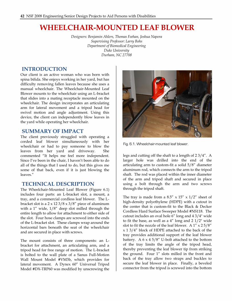
INTRODUCTION Our client is a six-year old boy with multiple physical and mental disabilities. He seeks independent movement and outside stimuli, desires that were satisfied through inappropriate, self-injurious behaviors. The Play Chair is a modified booster seat suspended from a custom frame with toy attachment points. The client can generate his own rocking movement, and play with the novel toys presented to him through the device.
SUMMARY OF IMPACT Since he outgrew his baby rocker, our client has not had an adequate, dependable, and safe way to satisfy his desires for independent movement and external stimuli. The Play Chair fills these, and provides a change from his confining wheelchair, where he spends a significant portion of his day. His primary caretaker says, “(He) loves the chair! It has been wonderful to have an additional positioning option for this very active little boy. He thoroughly enjoys the sensory input that he receives from using this chair.”
TECHNICAL DESCRIPTION The frame of the Play Chair (Figure 6.3) is constructed with 6105-T5 aluminum alloy from 80/20 Inc. Two aluminum side beams connected by a crossbeam make up the base of the frame. Two vertical beams are attached to each side beam. Joining plates hold the frame together. Custom-made Delrin plastic blocks secure four locking swivel casters to the bottom of the frame.
To serve as armrests, two 1”×4” spruce planks are mounted on top of the four vertical beams by corner brackets. To prevent the client from injuring himself when he hits the armrests with his hands, these wooden planks are padded with polyurethane. Waterproof vinyl fabric covers the armrests so that the client‟s caretakers can easily clean up any spills. U-bolts, cushioned with clear plastic tubing, are
fastened to the armrests to provide attachment points for toys. Additionally, two strips of Velcro are attached to each armrest to allow for more toys to be connected. The U-bolts and Velcro strips allow toys to be changed to continuously provide a novel source of entertainment for the client.
The seat of the Play Chair is a modified commercial booster seat (Evenflo Model No. 3341791A). An easily adjustable 3-strap seat belt is attached, holding the client comfortably and securely in the seat. To reinforce the seat base-to-back connection, two wooden back braces are attached. A wooden wedge inserted into the cavity between the base and the back significantly increases the rigidity of the base-to-back connection.
Two rubber straps suspend the booster seat within the frame. Carabiners connect the rubber straps to eyehooks on the vertical supports. The straps are
Fig. 6.3. Play chair.

Chapter 6: Duke University 45
strung through holes drilled in the base of the booster seat. Custom grommets made of high-density polyethylene plastic reinforce the holes where the rubber straps go through the chair.
To prevent the client from rocking too far forward or backward, two springs are attached from the shoulder section of the booster seat to the eye hooks
on the rear vertical beams via carabiners. Plastic tubing covers these springs so that they cannot scratch or pinch the client. Figure 6.4 shows the client sitting in the Play Chair. The cost for the chair is approximately $350.
Fig. 6.4. Client in play chair.

46 NSF 2008 Engineering Senior Design Projects to Aid Persons with Disabilities
SHOE HELPER Designers: Andy Huang, John Perkins and Alyx Rosen
Supervising Professor: Larry Bohs Department of Biomedical Engineering
Duke University Durham, NC 27708
INTRODUCTION Our client, a woman with cerebral palsy and limited mobility in her legs, requires up to 30 minutes putting on her shoes. The Shoe Helper, made from thermoplastic, consists of a shoehorn pivoting on top of a heel cup. While the heel cup prevents the heel of the shoe from folding under, the extra-wide shoehorn supports the client‟s heel and guides the foot into the shoe, regardless of the foot‟s entry angle. A string attached to the shoehorn allows the client to manipulate the hinge connecting the two plastic parts. The top of the shoehorn also serves as a sock aid, minimizing the number of dressing aids needed. The product is portable, adaptable to all shoes, and inexpensive to produce. Using the device, the client now puts on both socks and shoes in under four minutes.
SUMMARY OF IMPACT The client commented, “The combo sock/shoe assist works perfectly and saves me up to 30 minutes each time I use it. I never have to worry about the time it will take to put on shoes. It just takes a couple of minutes at most for both shoes. This device is life changing!”
TECHNICAL DESCRIPTION The Shoe Helper (Figure 6.5) includes a shoehorn and a heel cup, connected together with a metal hinge. Both the shoehorn and heel cup are constructed from hand-molded 1/8” thick thermoplastic. The shoehorn guides the user‟s heel and also serves as the main component of the sock
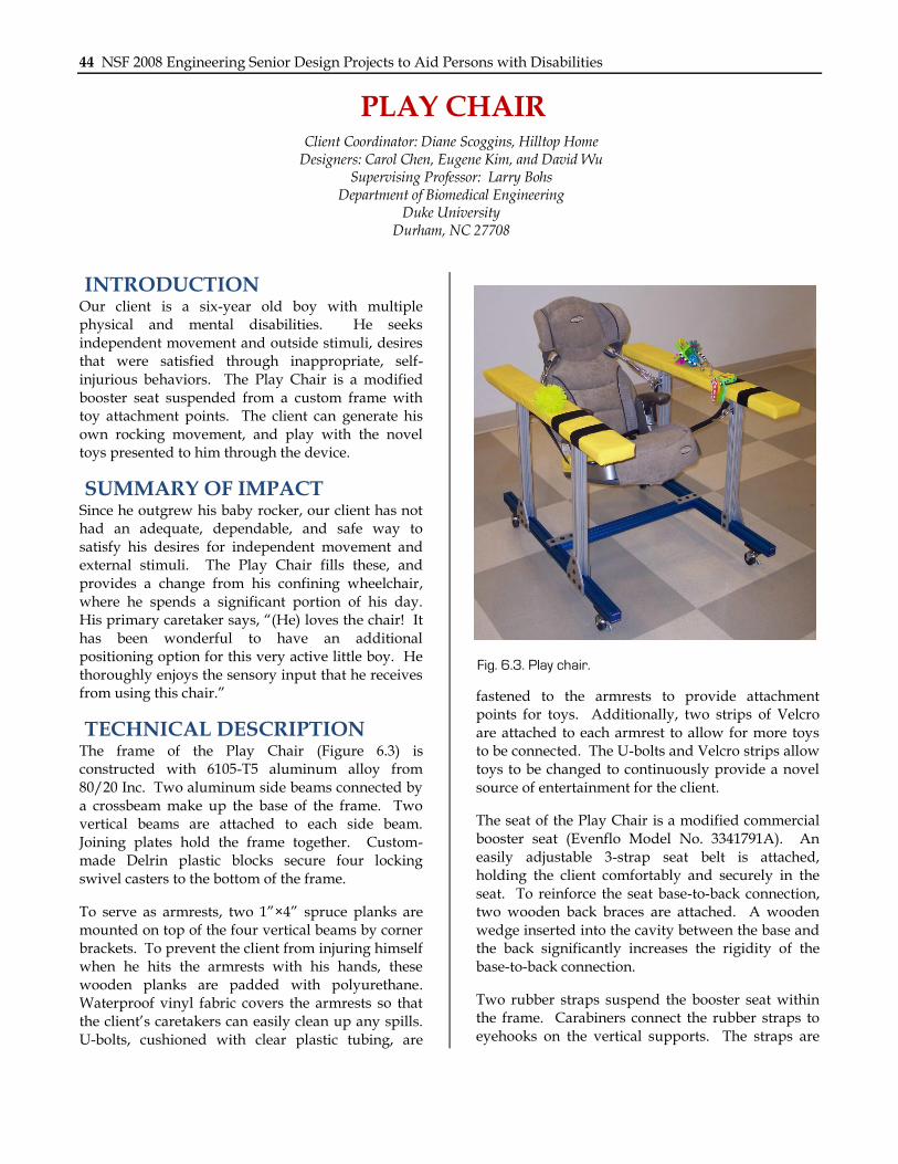
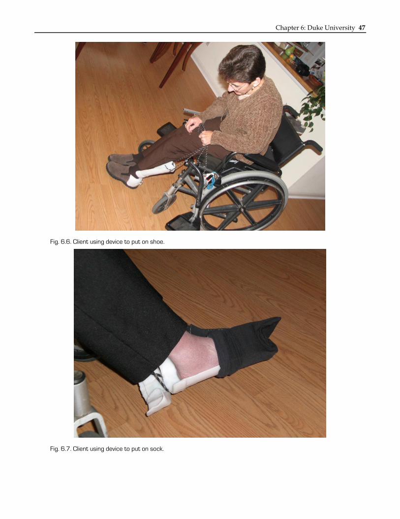
aid. The heel cup provides a rigid structure that prevents the heel of the shoe from collapsing. The widened rim allows the device to fit around a variety of different shoes. The shoehorn and heel cup are connected via a 2” steel strap hinge, sandwiched in place with thermoplastic. A 72” hiker‟s lace is attached to the top of the shoehorn to allow for rotation. For use as a sock aid, the string is first threaded through a thermoplastic bracket attached to the back of the heel cup, visible in Figure 6.6. This allows the user to pull forcefully on the string from the heel cup end of the device. Figure 6.6 shows the client using the device as a shoe helper. Figure 6.7 shows the client using the device as a sock aid. The device costs approximately $18 to replace.
Fig. 6.5. Shoe helper.
Chapter 6: Duke University 47
Fig. 6.6. Client using device to put on shoe.
Fig. 6.7. Client using device to put on sock.

48 NSF 2008 Engineering Senior Design Projects to Aid Persons with Disabilities
PORTABLE SUPPORT SEAT Client Coordinators: Nancy Curtis, Keri McCauley
Designers: Kristen Bova, Matt Hoover, Jesse Sandberg Supervising Professor: Larry Bohs
Department of Biomedical Engineering Duke University
Durham, NC 27708
INTRODUCTION Our client, an eight-year-old boy diagnosed with autism and cerebral palsy, can sit in a chair independently but needs help correcting his posture. Specifically, he needs assistance with proper hip placement and lateral trunk and spine support. We constructed the Portable Support Seat using high density polyethylene plastic (HDPE). The seat includes a hip belt and small side supports, and allows for adjustments to the seat angle as well as the seat depth. The Portable Support Seat is
lightweight and can be easily and efficiently attached to a wide variety of chairs using secure and safe lock straps. The device folds in half for easy transport and storage.
SUMMARY OF IMPACT Our client can now sit at the dinner table with proper and optimum posture. He no longer pushes his hips forward nor falls off the side of his chair. Since he is fully upright and able to have both arms on the table, he is more actively engaged in
Fig. 6.8. Portable support seat.

Chapter 6: Duke University 49
dinnertime activities, and his parents now have an easier time bringing him out to dinner with the rest of the family. According to our client‟s mother, “I am looking forward to taking our new chair on vacation with us to Disney World!”
TECHNICAL DESCRIPTION The frame of the Portable Support Seat (Figure 6.8) is made of two rectangular blocks of ½” HDPE. The seat bottom is 14.5”x12”x0.5” and the vertical back support is 14”x15”x0.5”. The seat and back support are connected with two 16 in-lbs. torque friction hinges. The vertical back support is mounted on a bottom support base of HDPE that is 16”x2”x0.5”. The back support is screwed into the support base with five 1.5” 10-32 flat head screws.
A length-adjustable padded lap belt is attached seven inches from the back of the seat bottom. Four webbing straps attach the seat to a supporting chair: two on either side of the underside of the seat bottom and two on the back of either side of the vertical back support. All of the webbing straps attach together via squeeze-release buckles. The straps are adjustable in length to allow for various seat sizes and to accommodate for the client‟s continued growth. Adjustable feet are mounted on 1.25”x1.5”x1.25” blocks of HDPE at the four corners of the seat bottom. The adjustable feet have heads that rotate and non-slip rubber bottoms. Each can be retracted and extended from its supporting HDPE block, thereby changing the angle between the seat and back of the chair.
On the underside of the seat bottom, a system is built into the chair to that allows the necessary adjustments to optimize the user‟s proper knee placement at rest. The adjustment system consists of two quarter- inch deep and half-inch wide milled square channels. In each channel, a 5.25”x0.5”x0.5” aluminum bar is positioned to slide through the channel. The two slide bars are connected by a 14”x0.5”x0.5” extension cross bar. This cross bar is padded with pipe insulation and covered with vinyl. The slide bars stay in place using two 1.5”x5”x0.5” blocks of aluminum. Each block has a 0.25” inch deep and 0.5” wide square channel milled vertically along its center. The milled channels in the aluminum support bases are each fit over one slide bar and screwed into the HDPE seat bottom. Each slide bar is held in place by two 0.25” set screws when the bars are in the proper position.
One and a half inches down from the top of either side of the vertical back support are two 3”x5.5”x0.25” HDPE lateral supports, which help support the client‟s trunk from side-to-side motion. A 0.25” deep and 5.5” long slot is milled into either side of the vertical back support. A 1”x5.5”.0.25” HDPE side support extender is fit into each slot. The lateral supports are aligned with these side support extenders and the entire side support system is screwed in place.
Lastly, the seat bottom, vertical back support, and lateral side supports are all covered with padded cushions. The seat cushion is 14”x10.75”.0.25”, the vertical back cushion is 14”x7”x0.25”, and the side cushions are each 5”x2”x0.25”. The cushions are constructed from ¼” plywood and layers of cotton sheets. They are wrapped in navy vinyl that is attached to the plywood with ¼” staples. Each cushion is attached to the HPDE via Velcro.
The Portable Support Seat weighs 10.5 lbs. Figure 6.9 shows our client in the device at the dinner table. The replacement cost is $260.
Fig. 6.9. Client using portable support seat.
50 NSF 2008 Engineering Senior Design Projects to Aid Persons with Disabilities
SILICONE TUBE CUTTER Client Coordinators: Alan Pitstick, John Wiltshire, Jon Kuniholm
Designers: Jason Liu, Meagan Gray, and Pallavi Kansal Supervising Professor: Larry Bohs
Department of Biomedical Engineering Duke University
Durham, NC. 27708
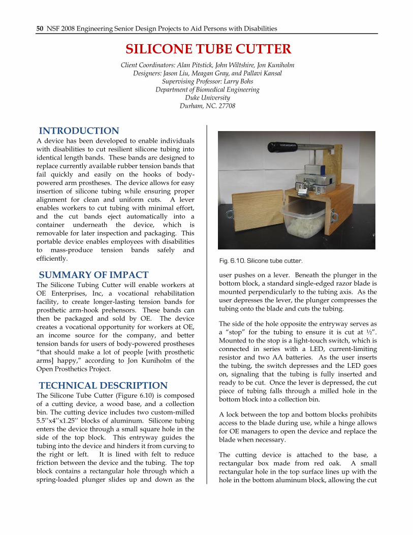
INTRODUCTION A device has been developed to enable individuals with disabilities to cut resilient silicone tubing into identical length bands. These bands are designed to replace currently available rubber tension bands that fail quickly and easily on the hooks of body-powered arm prostheses. The device allows for easy insertion of silicone tubing while ensuring proper alignment for clean and uniform cuts. A lever enables workers to cut tubing with minimal effort, and the cut bands eject automatically into a container underneath the device, which is removable for later inspection and packaging. This portable device enables employees with disabilities to mass-produce tension bands safely and efficiently.
SUMMARY OF IMPACT The Silicone Tubing Cutter will enable workers at OE Enterprises, Inc, a vocational rehabilitation facility, to create longer-lasting tension bands for prosthetic arm-hook prehensors. These bands can then be packaged and sold by OE. The device creates a vocational opportunity for workers at OE, an income source for the company, and better tension bands for users of body-powered prostheses “that should make a lot of people [with prosthetic arms] happy,” according to Jon Kuniholm of the Open Prosthetics Project.
TECHNICAL DESCRIPTION The Silicone Tube Cutter (Figure 6.10) is composed of a cutting device, a wood base, and a collection bin. The cutting device includes two custom-milled 5.5‟‟x4‟‟x1.25‟‟ blocks of aluminum. Silicone tubing enters the device through a small square hole in the side of the top block. This entryway guides the tubing into the device and hinders it from curving to the right or left. It is lined with felt to reduce friction between the device and the tubing. The top block contains a rectangular hole through which a spring-loaded plunger slides up and down as the
user pushes on a lever. Beneath the plunger in the bottom block, a standard single-edged razor blade is mounted perpendicularly to the tubing axis. As the user depresses the lever, the plunger compresses the tubing onto the blade and cuts the tubing.
The side of the hole opposite the entryway serves as a “stop” for the tubing to ensure it is cut at ½”. Mounted to the stop is a light-touch switch, which is connected in series with a LED, current-limiting resistor and two AA batteries. As the user inserts the tubing, the switch depresses and the LED goes on, signaling that the tubing is fully inserted and ready to be cut. Once the lever is depressed, the cut piece of tubing falls through a milled hole in the bottom block into a collection bin.
A lock between the top and bottom blocks prohibits access to the blade during use, while a hinge allows for OE managers to open the device and replace the blade when necessary.
The cutting device is attached to the base, a rectangular box made from red oak. A small rectangular hole in the top surface lines up with the hole in the bottom aluminum block, allowing the cut
Fig. 6.10. Silicone tube cutter.

Chapter 6: Duke University 51
bands to fall into the collection bin, a commercial plastic container. A hinged door on the front of the base is locked during use so that workers cannot insert hands into the cutting area.
The lever is constructed from 2.5‟ of ¾” steel electrical conduit. A 1.5x3.5x7.5‟‟ piece of wood serves as the lever fulcrum. A key-shaped hole allows the plunger bolt to insert easily and slide as the plunger arm pivots. An OE Enterprise manager can easily remove the lever by unscrewing the fulcrum bolt and then sliding the lever towards its
fulcrum, thereby allowing access to the cutting chamber.
The tubing must be held with its natural curvature as shown in Figure 6.11 for the most accurate cuts. This can be done by the user, as shown, or a reel of tubing can be mounted above the device. Cost of materials for the Silicone Tube Cutter was approximately $160.
Fig. 6.11. Client using the device.
52 NSF 2008 Engineering Senior Design Projects to Aid Persons with Disabilities
CYLINDRICAL BOTTLE LABEL APPLICATOR Client Coordinators: Joe Bumgarner, John Wiltshire
Designers: Matthew Dekow, Gregory Meyers, Cameron Smith Supervising Professor: Larry Bohs
Department of Biomedical Engineering Duke University
Durham, NC 27708
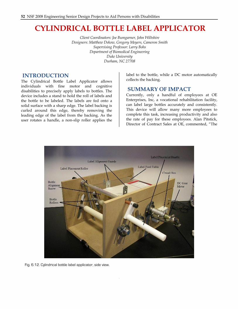
INTRODUCTION The Cylindrical Bottle Label Applicator allows individuals with fine motor and cognitive disabilities to precisely apply labels to bottles. The device includes a stand to hold the roll of labels and the bottle to be labeled. The labels are fed onto a solid surface with a sharp edge. The label backing is curled around this edge, thereby removing the leading edge of the label from the backing. As the user rotates a handle, a non-slip roller applies the
label to the bottle, while a DC motor automatically collects the backing.
SUMMARY OF IMPACT Currently, only a handful of employees at OE Enterprises, Inc, a vocational rehabilitation facility, can label large bottles accurately and consistently. This device will allow many more employees to complete this task, increasing productivity and also the rate of pay for these employees. Alan Pitstick, Director of Contract Sales at OE, commented, “The
Fig. 6.12. Cylindrical bottle label applicator, side view.

Chapter 6: Duke University 53
use of the machine will allow more of the workforce to be involved in bottle labeling which is central to the mission of OE Enterprises.”
TECHNICAL DESCRIPTION Our design, shown in Figure 6.12 and Figure 6.13, includes a label holder, backing removal mechanism, label placement apparatus, and label alignment guards. The label holder includes a tailpipe expander, two flange bearings, a friction clutch, a socket, and an aluminum rod. The tailpipe expander allows label rolls with differing shank diameters to be held securely. The friction clutch is attached to the tailpipe expander, providing the rotational friction necessary to keep tension on the sheet of labels for the label backing removal mechanism.
The label backing removal mechanism separates the backing from the adhesive label by curling the label backing around the end of the label feed table, a sheet of ¼” thick acrylic. The label backing collector, a wooden dowel with an axial slit, resides underneath the table and collects the backing to be discarded. A DC gear motor applies a constant torque, slightly less than that required to remove labels from the backing, but sufficient to wind the backing onto the collector.
The label placement apparatus includes two silicone rubber-sheathed aluminum rods, the bottle rollers, supported by flange bearings mounted to angled
height-adjustment tracks routed in the sideboards. This arrangement allows the height and separation of the bottle rollers to be easily adjusted to accommodate bottles of different sizes. A label placement roller secures the bottle from the top and firmly rolls the label onto the bottle. Two extension springs add downward tension to the roller, allowing the user to simultaneously rotate the bottle and apply the label by turning a handle.
The bottle and the label are held in alignment with the label alignment guards and two bottle alignment screws. The label alignment guards are 1” L-brackets that face the center of the label feed table. The bottle alignment screws prevent the bottle from sliding along the axis of the bottle rollers, and can be moved to various set positions corresponding to different bottle sizes. Once appropriately set for a particular bottle size, these components make it simple for the user to align the bottle and label, and then to gently press the edge of the label onto the bottle to initiate contact between the adhesive side of the label and the bottle. The user then slides a finger down the edge of the label and rotates the bottle using the handle on the label placement roller, causing the remainder of the label to adhere to the surface of the bottle. The roller pushes down on the bottle, removing any bubbles that have formed at the label-bottle interface. As this process occurs, the label backing collector automatically collects the excess label backing. Cost of parts for the device was $325.
Fig. 6.13. Cylindrical bottle labeler, front view.

54 NSF 2008 Engineering Senior Design Projects to Aid Persons with Disabilities
CUSTOM TRICYCLE Designers: Alex Feng, Lola Xie, Jessica Zinck
Supervising Professors: Kevin Caves, Richard Goldberg Department of Biomedical Engineering
Duke University Durham, NC 27708
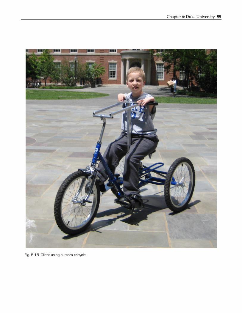
INTRODUCTION Our client, an 8-year-old boy with Thrombocytopenia Absent Radius (TAR) Syndrome, cannot use a standard tricycle independently because his arms are weak and very short. Braking is difficult due to his limited ability to squeeze a hand brake. Additionally, his right leg has limited range of motion and he cannot effectively pedal with that leg. We modified a commercial tricycle intended for older children so that he could ride it easily. We made modifications to the steering, braking, and the hub.
SUMMARY OF IMPACT The client‟s mother commented, “No one who has normal children ever realizes how much it breaks your heart when your child says to you „Mommy and Daddy, I want to ride a bike like my brother and sister‟ and they are physically unable to do this due to special needs. These students and North Carolina Sports for Special Kids (NCSSK), have made this a possibility for [my son]. This bike has enabled him to become just a „normal‟ kid in one aspect of his life and that is something that is so valuable to our family that few will ever know.”
TECHNICAL DESCRIPTION The handle bars were removed from a commercially available Triaid tricycle and replaced with a four-bar linkage steering mechanism (Figure 6.14). The four-bar linkage moves the point of rotation of the handlebars back, so our client can use his considerable trunk rotation to steer the bike. The steering system was fabricated from 7/8” aluminum square tubes due to their light weight, low cost and corrosion resistance. A round, hollow vertical stabilizing rod made of the same aluminum alloy was added to the tricycle to stabilize the 4-bar linkage at the center horizontal bar. Both the vertical stabilizing rod and the long steering bars are adjustable in length to accommodate the client as he continues to grow. Finally, mountain bike hand
grips were added to the ends of the steering mechanism to provide a larger surface for the rider to push against and stabilize him by gripping with his hands and fingers.
Because the client has poor range of motion on his right leg, he could not use the right foot to pedal. We removed that pedal and put a platform in its place to rest his foot. In addition, the client is not able to effectively use hand brakes, so we connected one end of the brake cable to that platform. When he presses on the platform, it pulls on the brake cable to activate the cantilever brakes. This allows the client to brake using his right foot, while pedaling with the left foot. In addition, the rear gear sprocket was changed to a smaller, free wheel system to allow the bike to move faster and to coast like a standard bicycle. The overall design focused on ease of use, independence, versatility, cost-effectiveness, and aesthetic appeal.
Figure 6.15 shows the client using the Custom Tricycle. Cost of the commercial tricycle was covered by a donation from NCSSK. The cost of the parts for the modification of the steering, braking and gearing was approximately $300.
Fig. 6.14. Custom tricycle.
Chapter 6: Duke University 55
Fig. 6.15. Client using custom tricycle.

56 NSF 2008 Engineering Senior Design Projects to Aid Persons with Disabilities
PROSTHETIC CLIMBING AID Designers: Clark Daniel, Ben Haynes, Archana Ramireddy, and Karli Spetzler
Supervising Professor: Kevin Caves and Richard Goldberg Department of Biomedical Engineering
Duke University Durham, NC 27708
INTRODUCTION Our client is an adult with a below elbow amputation on his left side, who wants to regain his ability to rock climb. He has full shoulder motion, but only flexion/extension at his left elbow. He also lacks the ability to pronate and supinate his prosthetic forearm. The goal of this project was to design an attachment to his carbon fiber socket that will increase his ability to rock climb both indoor and outdoor surfaces. The Prosthetic Climbing Aid uses a set of modified ice axe blades that are set in a rotating aluminum block. The block has 60 degrees of motion and simulates the inversion/eversion motion of the wrist to give him as much range of motion as possible. The device rotates freely when unloaded, but it locks into one of 5 set positions when weight is placed on the arm to prevent it from slipping from the desired grip.
SUMMARY OF IMPACT The client commented, “The device the students built allows for a couple things. Because of the lateral movement available in the wrist I have a wider variety of holds I can get to, as well as being able to attain some angles of attack that were previously unavailable. And the increased surface area of the “fingers” allows me a more stable position to work from. All in all, it provides for a better degree of mechanical advantage which in turns makes climbing a little more solid and stable for me.”
TECHNICAL DESCRIPTION Climbing Prosthesis A ¾” diameter aluminum rod was used to attach to the climbing prosthesis to client‟s existing carbon fiber socket. The rod fits into the rotation mechanism which is made from two pieces of 6061 Aluminum Alloy and holds three custom fabricated ice axe blades made from Type 303 stainless steel (Figure 6.16).
Fig. 6.16. Prosthetic climbing aid attached to the client’s
existing carbon fiber prosthetic arm.

Chapter 6: Duke University 57
An hourglass-shaped hole has been machined to allow the rod to fit inside the rotation mechanism. A barrel bolt provides a pivot point for the rotation of the device. Figure 6.17 shows the inner face of the rotation mechanism where there are a series of 3/16” grooves that accept a 1/8” coiled spring pin attached to the aluminum rod. The pin slides into one of the slots when the arm is pulled on a rock surface. This locks the rotation mechanism when loaded. When the device is unloaded, the rotation mechanism is free to rotate, but when loaded, the device slides up the rod and the coiled pin rests into one of five grooves, locking it in the specific angle. The weight-bearing element is the coiled spring pin that is rated for 2,000 lbs. of double shear stress. The length of the rod puts the ice axe blades in the same plane as the fingers of his right hand, allowing him a more stable, natural climbing experience.
Device Harness The device harness is used to reduce the amount of stress placed on the elbow strap of the prosthesis. It is not intended as a weight-bearing device. A bungee cord is used to transfer weight from the prosthesis to the harness. A tricep cuff that attaches to the prosthesis was provided by our client. A ¼”-diameter bungee cord attaches the harness to this cuff and is always in tension. The cuff remains snuggly on our client‟s upper arm using a 1” elastic
band with a Velcro attachment. The material for the major straps is 1” nylon webbing rated at 14 kN tensile strength. To keep the harness from sliding up his body and getting out of position, this harness is connected to the client‟s actual climbing harness with two cinch lock buckles in the back and two side release buckles in the front. The side release buckles were used to allow for frequent adjustment that can be manipulated with one hand.
Figure 6.18 shows the client climbing with the device. Cost of parts for the device was approximately $170.
Fig. 6.18. Client using climbing prosthesis.
Fig. 6.17. Inside face of the climbing prosthesis.

58 NSF 2008 Engineering Senior Design Projects to Aid Persons with Disabilities
FLIGHT SIMULATION STATION Designers: Alexa Issa, Neha Krishnamohan, and Swara Paranjape
Supervising Professors: Kevin Caves and Richard Goldberg Department of Biomedical Engineering
Duke University Durham, NC 27708
INTRODUCTION Our client is an active retiree with a slow progressing form of Amyotropic Lateral Sclerosis (ALS). He worked in the aerospace industry, and now enjoys playing flight simulator computer games. He uses a wheelchair for mobility and has limited strength in his arms. He has special flight controls that allow him to more realistically control the simulator. These flight simulator controllers had been mounted to a plywood base. Due to his weakened arms, however, it became difficult for him to switch between using the flight simulator controllers and using the computer keyboard and mouse. We developed a device that provided for ergonomic positioning of the controllers, mouse and other equipment needed for the flight simulator game. The device also is easily stored when the computer was needed for other activities.
SUMMARY OF IMPACT The client stated that “it‟s going to make it just a lot easier, because my hands are lower to start with, and I am more relaxed because usually I am sitting up at my computer desk and now I can sit back and still move the controls around, it is going to be a big help. The system is great for me as I now can easily move my hands onto the controls as they now sit at a level that is comfortable with my arms resting on the wheelchair arm rests. Also, as it is closer to my body, I am better positioned in my chair- not having to lean forward to reach the controls when they were on the computer table before. Having the place for the mouse between the control elements makes it easy to access the on-screen icons to make changes in the flight simulation conditions such as weather, location, plane selection, etc. I can sit back and still move the controls around. This project has made my continued enjoyment of flight simulation possible for a long time to come.”
TECHNICAL DESCRIPTION The Flight Simulation Station (Figure 6.19) is made from an acrylic tray that holds the flight simulator
controls. When not in use, the tray can slide and pivot to a storage position using two drawer slides and a lazy Susan pivot. The lazy Susan is attached to an oak platform, which is bolted into the client‟s computer desk. The device is designed so that the client can rotate and slide the flight controls independently and at the most comfortable position. This allows him to easily switch between using the flight controls, and using the standard keyboard and mouse.
The device is attached to the right side of his computer desk. The 25'' by 7.25'' acrylic tray rotates thru an angle of about 110 degrees on the lazy Susan, and extends 20” on the two drawer slides.
To make the device stable, a docking platform was attached to the left side of the client‟s wheelchair. The left edge of the acrylic tray slides into this dock and holds the tray and control steady. The right side also has a locking bar that prevents rotation of the tray while in use. Additionally, pair of rollers was attached to the underside of the oak support that provides a counter force to resist the moment of the extended tray.
Fig. 6.19. Flight simulation station.

Chapter 6: Duke University 59
The flight simulator controls are attached to the acrylic tray via Velcro. The system enables the client stowed and extended his controls independently
and with ease. Figure 6.20 shows the client using the Flight Simulation Station. Cost of parts for the device was approximately $217.
Fig. 6.20. Client using flight simulation station.
60 NSF 2008 Engineering Senior Design Projects to Aid Persons with Disabilities
PORTABLE MINI-GOLF WITH PUTTING ASSIST Client Coordinator: Marc Roth
Designers: Christine Bestvina and Danial Bokhari Supervising Professors: Kevin Caves and Richard Goldberg
Department of Biomedical Engineering Duke University
Durham, NC 27708
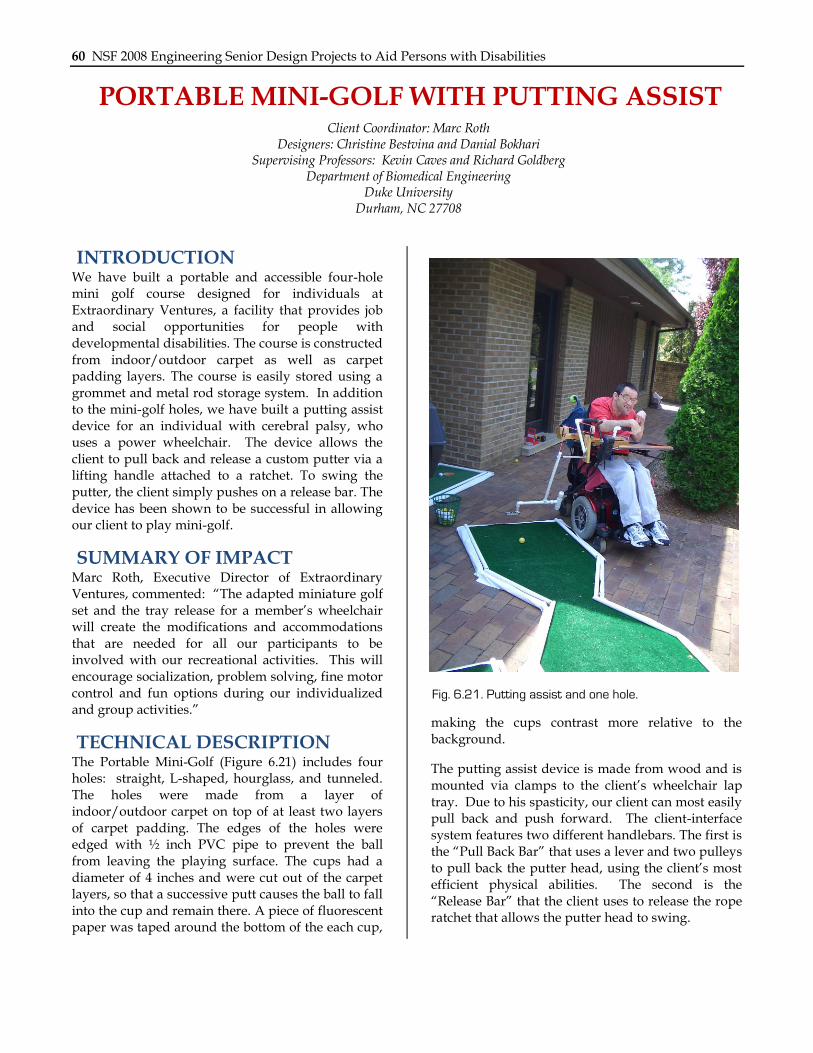
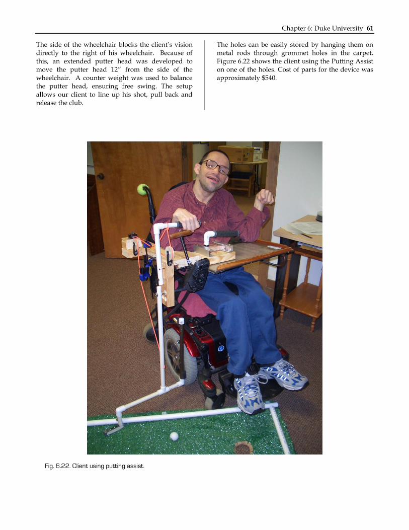
INTRODUCTION We have built a portable and accessible four-hole mini golf course designed for individuals at Extraordinary Ventures, a facility that provides job and social opportunities for people with developmental disabilities. The course is constructed from indoor/outdoor carpet as well as carpet padding layers. The course is easily stored using a grommet and metal rod storage system. In addition to the mini-golf holes, we have built a putting assist device for an individual with cerebral palsy, who uses a power wheelchair. The device allows the client to pull back and release a custom putter via a lifting handle attached to a ratchet. To swing the putter, the client simply pushes on a release bar. The device has been shown to be successful in allowing our client to play mini-golf.
SUMMARY OF IMPACT Marc Roth, Executive Director of Extraordinary Ventures, commented: “The adapted miniature golf set and the tray release for a member‟s wheelchair will create the modifications and accommodations that are needed for all our participants to be involved with our recreational activities. This will encourage socialization, problem solving, fine motor control and fun options during our individualized and group activities.”
TECHNICAL DESCRIPTION The Portable Mini-Golf (Figure 6.21) includes four holes: straight, L-shaped, hourglass, and tunneled. The holes were made from a layer of indoor/outdoor carpet on top of at least two layers of carpet padding. The edges of the holes were edged with ½ inch PVC pipe to prevent the ball from leaving the playing surface. The cups had a diameter of 4 inches and were cut out of the carpet layers, so that a successive putt causes the ball to fall into the cup and remain there. A piece of fluorescent paper was taped around the bottom of the each cup,
making the cups contrast more relative to the background.
The putting assist device is made from wood and is mounted via clamps to the client‟s wheelchair lap tray. Due to his spasticity, our client can most easily pull back and push forward. The client-interface system features two different handlebars. The first is the “Pull Back Bar” that uses a lever and two pulleys to pull back the putter head, using the client‟s most efficient physical abilities. The second is the “Release Bar” that the client uses to release the rope ratchet that allows the putter head to swing.
Fig. 6.21. Putting assist and one hole.
Chapter 6: Duke University 61
The side of the wheelchair blocks the client‟s vision directly to the right of his wheelchair. Because of this, an extended putter head was developed to move the putter head 12” from the side of the wheelchair. A counter weight was used to balance the putter head, ensuring free swing. The setup allows our client to line up his shot, pull back and release the club.
The holes can be easily stored by hanging them on metal rods through grommet holes in the carpet. Figure 6.22 shows the client using the Putting Assist on one of the holes. Cost of parts for the device was approximately $540.
Fig. 6.22. Client using putting assist.
62 NSF 2008 Engineering Senior Design Projects to Aid Persons with Disabilities
SENSORY STATION Client Coordinator: Shauneille Smith
Designers: Tiffany Chang, Craig Silverman, Wailan Yip Supervising Professor: Kevin Caves and Richard Goldberg
Department of Biomedical Engineering Duke University
Durham, NC 27708
INTRODUCTION This project was designed for two elementary aged children in a special education classroom. These children have severe and profound mental and physical disabilities that include being non-verbal, non-ambulatory, low-vision, and cognitively impaired. The children are developing their cognitive and perceptive abilities through the use of cause-and-effect toys and sensory stimuli. Their teacher requested a sensory environment that will minimize distractions from the classroom and will aid them in achieving their educational goals. We built a tent structure and electronics package to assist developing manipulation skills, keeping the child‟s head in a raised position, increasing perceptive abilities, and allowing the child to make a preference for which toy he would enjoy most.
SUMMARY OF IMPACT The classroom teacher reports: “The station provides an opportunity for students to be in an upright and seated position; while being engaged in activities free from distractions. The enclosed station assists in having students sharpened their sense of hearing; as well as focus on manipulation within the station rather than focus on other activities within the classroom setting.”
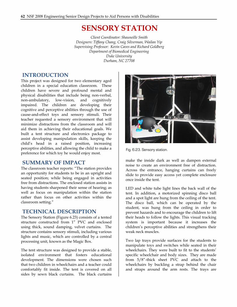
TECHNICAL DESCRIPTION The Sensory Station (Figure 6.23) consists of a tented structure constructed from 1” PVC and enclosed using thick, sound damping, velvet curtains. The structure contains sensory stimuli, including various lights and music, which are controlled by a central processing unit, known as the Magic Box.
The tent structure was designed to provide a stable, isolated environment that fosters educational development. The dimensions were chosen such that two children in wheelchairs and a teacher could comfortably fit inside. The tent is covered on all sides by sewn black curtains. The black curtains
make the inside dark as well as dampen external noise to create an environment free of distraction. Across the entrance, hanging curtains can freely slide to provide easy access yet complete enclosure once inside the tent.
LED and white tube light lines the back wall of the tent. In addition, a motorized spinning disco ball and a spot light are hung from the ceiling of the tent. The disco ball, which can be operated by the student, was hung from the ceiling in order to prevent hazards and to encourage the children to lift their heads to follow the lights. This visual tracking system is important because it increases the children‟s perceptive abilities and strengthens their weak neck muscles.
Two lap trays provide surfaces for the students to manipulate toys and switches while seated in their wheelchairs. They were built to fit to the students‟ specific wheelchair and body sizes. They are made from 5/8”-thick sheet PVC and attach to the wheelchairs by buckling a strap behind the chair and straps around the arm rests. The trays are
Fig. 6.23. Sensory station.
Chapter 6: Duke University 63
durable, easily sanitized, and can be quickly installed and uninstalled.
The Magic Box functions as a cause-effect control box. When the child presses a switch, the Magic Box activates the appropriate stimulation according to one of the 5 teacher-selectable operating modes:
1. Play Cassette/Radio (5 second duration)
2. Play Cassette/Radio (15 second duration)
3. Operate Switch Adapted Toys (5 second duration)
4. Play CD Boom Box (play/pause)
5. Auditory Tracking
Modes 1, 2 and 4 enable the child to control a switched-enabled CD Boom Box (Enabling Devices, Hastings on Hudson, NY). Modes 1-3 have a duration time, and when that time has elapsed, the
Magic Box automatically turns off the stimulation. This forces the child to pick up his hand and to re-press the switch if he wants the stimulation to continue. In this way, this mode encourages the children to actively move their hands, one of their key educational goals.
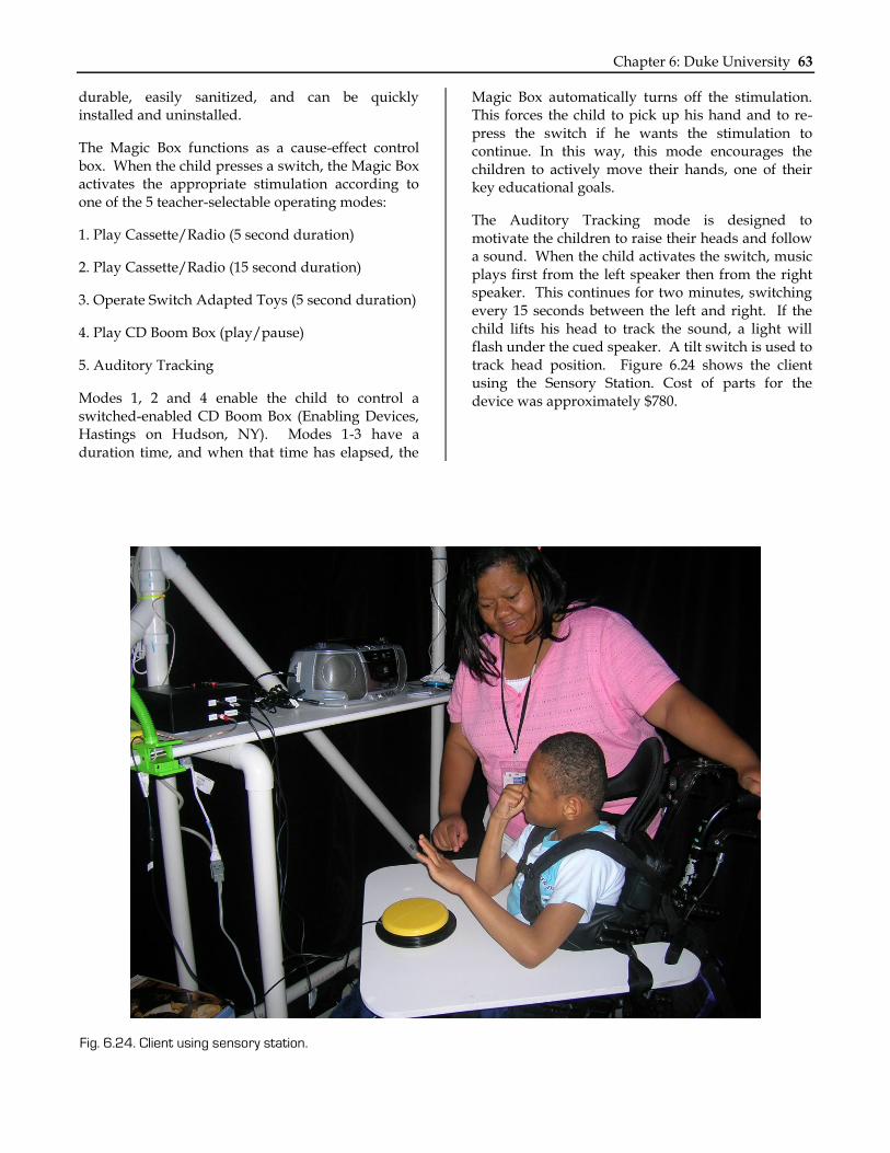
The Auditory Tracking mode is designed to motivate the children to raise their heads and follow a sound. When the child activates the switch, music plays first from the left speaker then from the right speaker. This continues for two minutes, switching every 15 seconds between the left and right. If the child lifts his head to track the sound, a light will flash under the cued speaker. A tilt switch is used to track head position. Figure 6.24 shows the client using the Sensory Station. Cost of parts for the device was approximately $780.
Fig. 6.24. Client using sensory station.

64 NSF 2008 Engineering Senior Design Projects to Aid Persons with Disabilities
MULTI-FUNCTION WORK TABLE Designers: Jeff Barry, Joseph Kuo, Peter Zolides
Supervising Professors: Kevin Caves, Richard Goldberg Department of Biomedical Engineering
Duke University Durham, NC 27708
INTRODUCTION Our client has a slow progressing form of amyotrophic lateral sclerosis, which results in weakness in his upper arms and legs. As such, he spends much of his time in a wheelchair. He likes to read and work on crossword puzzles but it is awkward for him to rest his book or puzzle on a table or a TV tray because it strains his neck. We designed a portable table that attaches to the clients wheelchair and tilts, allowing him to position his book or crossword puzzle in a comfortable, ergonomic position.
SUMMARY OF IMPACT Our client stated, “I haven‟t been able to read more than one book since moving here; with this new table, I‟m looking forward to getting back to reading on a regular basis.”
TECHNICAL DESCRIPTION The Multi-Function Work Table (Figure 6.25) is made from quarter-inch thick sheet of Acrylite. It is attached to a furniture grade PVC tube frame that enables the tray to tilt and swing to the side. The tray has a wrist rest at the edge closest to the client, which also serves as a book support when the tray is in book reading mode.
The table consists of two main parts: a mount that is semi-permanently attached to the chair, and a table that is easily attached and removed. A 1” diameter steel tube was attached to the wheelchair via custom plastic mounts that hold the table at the correct height. The table has a ¾” steel bar that inserts into the 1” tube on the wheelchair. The tubes are machined such that the tray can be flipped up 100 degrees to the side, so the client can get out of his chair without removing the tray.
The surface of the tray can be tilted toward the client and locks into place at an angle of 55 degrees. The
padded wrist rest serves as a book rest when in this position. The book rest slides in slots milled into the tray surface and can be moved to three different positions to accommodate books of different sizes.
The writing surface is made from Acrylite, a durable and light and surface for writing. It is covered by a sheet of custom-fit InvisibleShield®. This is a material used to coat expensive electronic devices to protect them from scratches. Two section of Stickypad® are attached to the upper left and right corners of the tray, providing a non-slip surface for items such as a pencil or cell phone. Cost of parts was about $240.
Fig. 6.25. Multi-function work table.

Chapter 6: Duke University 65
Fig. 6.26. Client using multi-function work table.

66 NSF 2008 Engineering Senior Design Projects to Aid Persons with Disabilities