Embed Size (px)
Citation preview
Copyright © by Holt, Rinehart and Winston. All rights reserved.
ResourcesChapter menu
Table of Contents
Chapter 6 Chemical Bonding
Section 1 Introduction to Chemical Bonding
Section 2 Covalent Bonding and Molecular Compounds
Section 3 Ionic Bonding and Ionic Compounds
Section 4 Metallic Bonding
Section 5 Molecular Geometry
Copyright © by Holt, Rinehart and Winston. All rights reserved.
ResourcesChapter menu
Objectives
• Define chemical bond.
• Explain why most atoms form chemical bonds.
• Describe ionic and covalent bonding.
• Explain why most chemical bonding is neither purely
ionic nor purely covalent.
• Classify bonding type according to
electronegativity differences.
Section 1 Introduction to
Chemical BondingChapter 6
Copyright © by Holt, Rinehart and Winston. All rights reserved.
ResourcesChapter menu
Visual Concepts
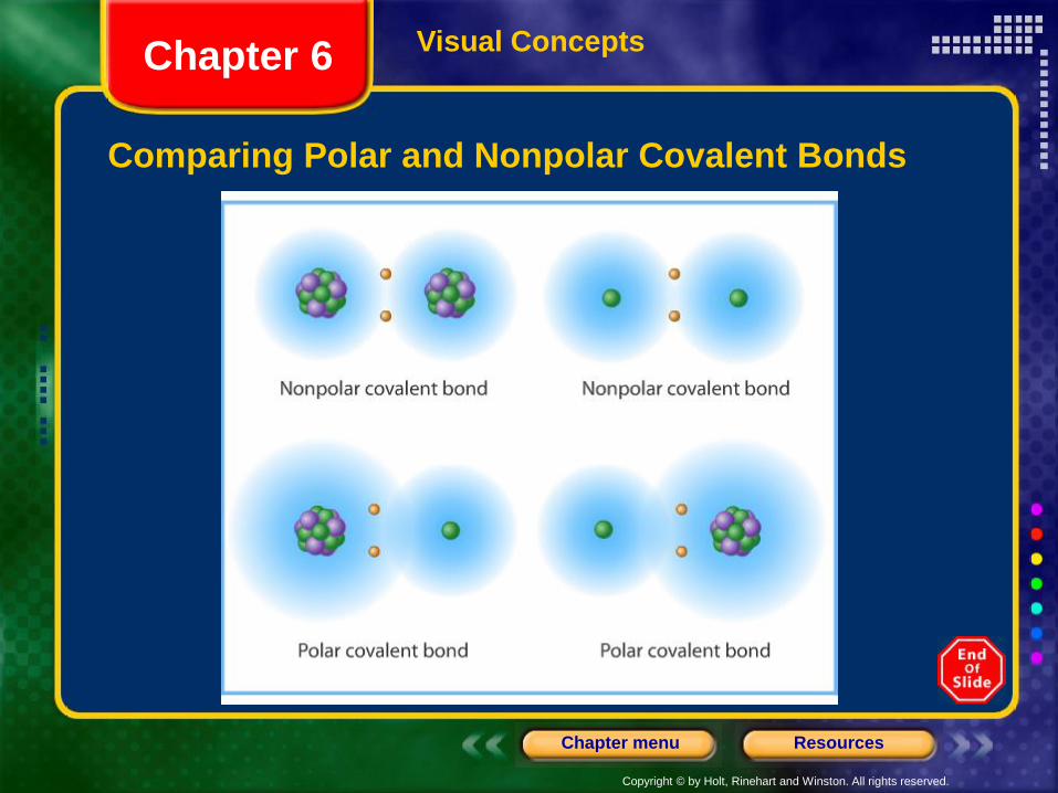
Comparing Polar and Nonpolar Covalent Bonds
Chapter 6
Copyright © by Holt, Rinehart and Winston. All rights reserved.
ResourcesChapter menu
Visual Concepts
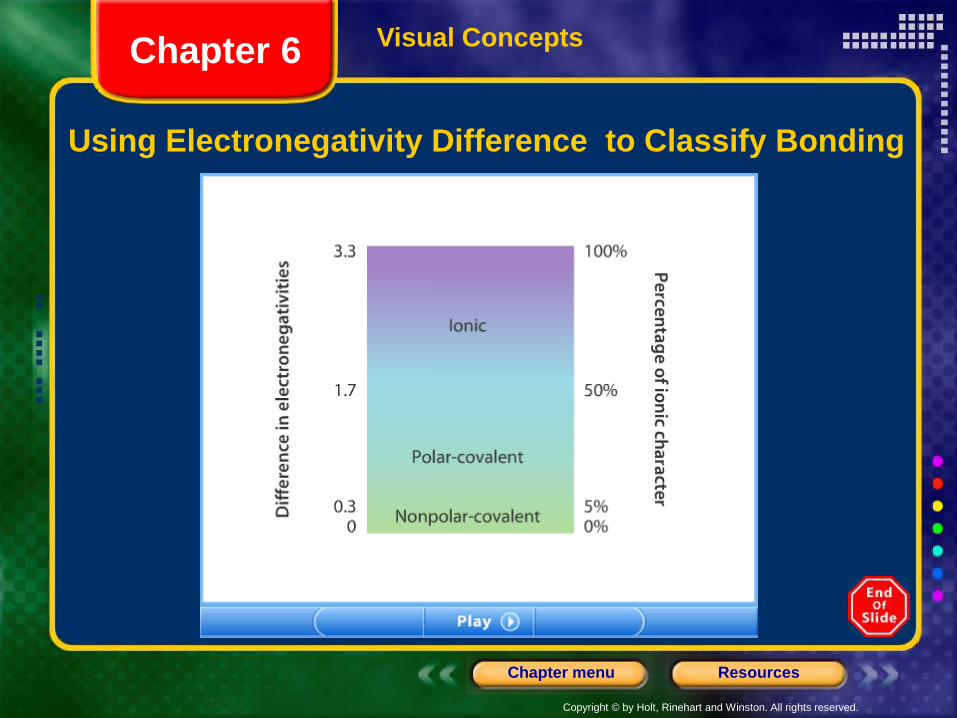
Using Electronegativity Difference to Classify Bonding
Chapter 6
Copyright © by Holt, Rinehart and Winston. All rights reserved.
ResourcesChapter menu
Chemical Bonding, continued
Sample Problem A
Use electronegativity values listed in Figure 20 from the
previous chapter in your book, on page 161, and Figure
2 in your book, on page 176, to classify bonding
between sulfur, S, and the following elements:
hydrogen, H; cesium, Cs; and chlorine, Cl. In each pair,
which atom will be more negative?
Section 1 Introduction to
Chemical BondingChapter 6
Copyright © by Holt, Rinehart and Winston. All rights reserved.
ResourcesChapter menu
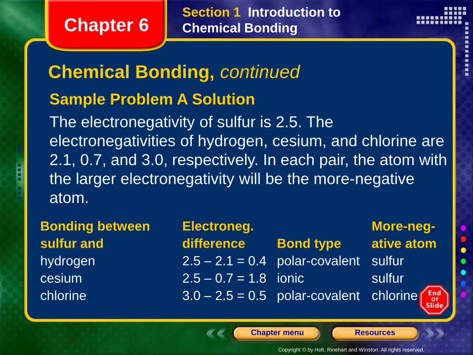
Sample Problem A Solution
The electronegativity of sulfur is 2.5. The
electronegativities of hydrogen, cesium, and chlorine are
2.1, 0.7, and 3.0, respectively. In each pair, the atom with
the larger electronegativity will be the more-negative
atom.
Section 1 Introduction to
Chemical BondingChapter 6
Bonding between Electroneg. More-neg-
sulfur and difference Bond type ative atom
hydrogen 2.5 – 2.1 = 0.4 polar-covalent sulfur
cesium 2.5 – 0.7 = 1.8 ionic sulfur
chlorine 3.0 – 2.5 = 0.5 polar-covalent chlorine
Chemical Bonding, continued
Copyright © by Holt, Rinehart and Winston. All rights reserved.
ResourcesChapter menu
Objectives
• Define molecule and molecular formula.
• Explain the relationships among potential energy,
distance between approaching atoms, bond length,
and bond energy.
• State the octet rule.
Chapter 6Section 2 Covalent Bonding and
Molecular Compounds
Copyright © by Holt, Rinehart and Winston. All rights reserved.
ResourcesChapter menu
Objectives, continued
• List the six basic steps used in writing
Lewis structures.
• Explain how to determine Lewis structures for
molecules containing single bonds, multiple bonds,
or both.
• Explain why scientists use resonance structures to
represent some molecules.
Section 2 Covalent Bonding and
Molecular CompoundsChapter 6
Copyright © by Holt, Rinehart and Winston. All rights reserved.
ResourcesChapter menu
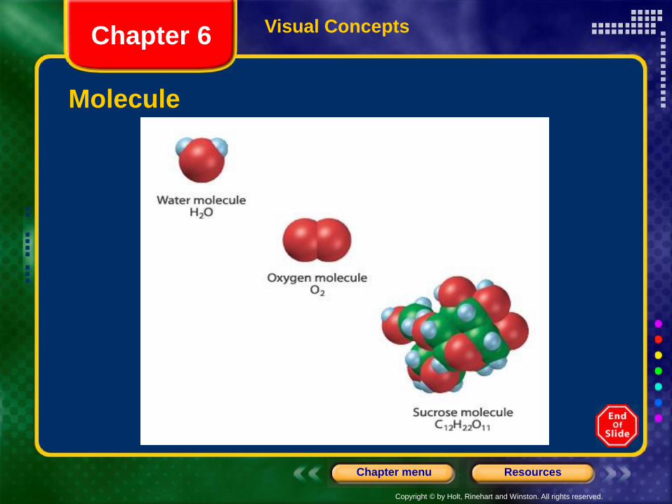
Molecular Compounds
• A molecule is a neutral group of atoms that are held
together by covalent bonds.
• A chemical compound whose simplest units are
molecules is called a molecular compound.
Section 2 Covalent Bonding and
Molecular CompoundsChapter 6
Copyright © by Holt, Rinehart and Winston. All rights reserved.
ResourcesChapter menu
Visual Concepts
Molecule
Chapter 6
Copyright © by Holt, Rinehart and Winston. All rights reserved.
ResourcesChapter menu
Molecular Compounds
• The composition of a compound is given by its
chemical formula.
• A chemical formula indicates the relative numbers of
atoms of each kind in a chemical compound by using
atomic symbols and numerical subscripts.
• A molecular formula shows the types and numbers
of atoms combined in a single molecule of a
molecular compound.
Section 2 Covalent Bonding and
Molecular CompoundsChapter 6
Copyright © by Holt, Rinehart and Winston. All rights reserved.
ResourcesChapter menu
Visual Concepts
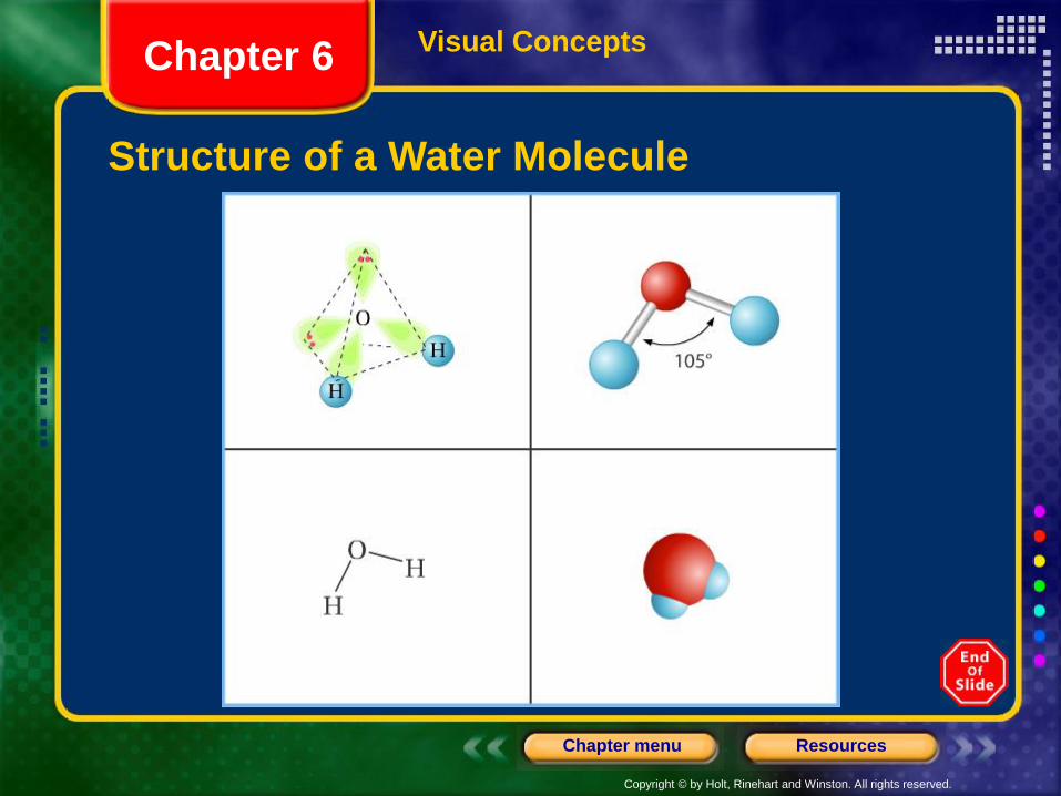
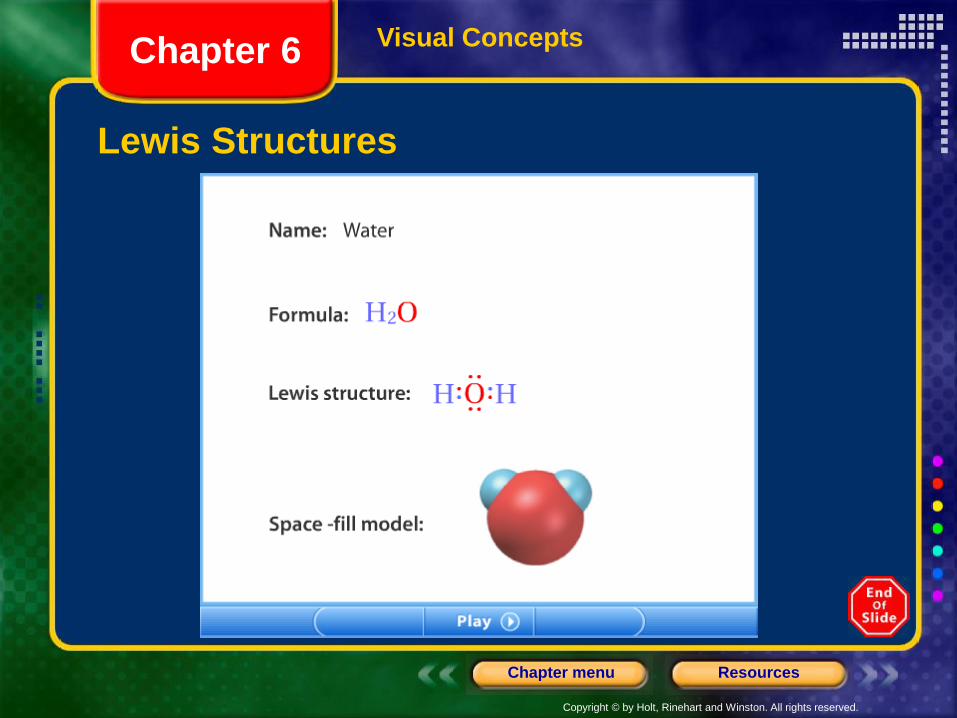
Structure of a Water Molecule
Chapter 6
Copyright © by Holt, Rinehart and Winston. All rights reserved.
ResourcesChapter menu
Visual Concepts
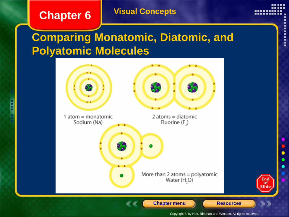
Comparing Monatomic, Diatomic, and
Polyatomic Molecules
Chapter 6
Copyright © by Holt, Rinehart and Winston. All rights reserved.
ResourcesChapter menu
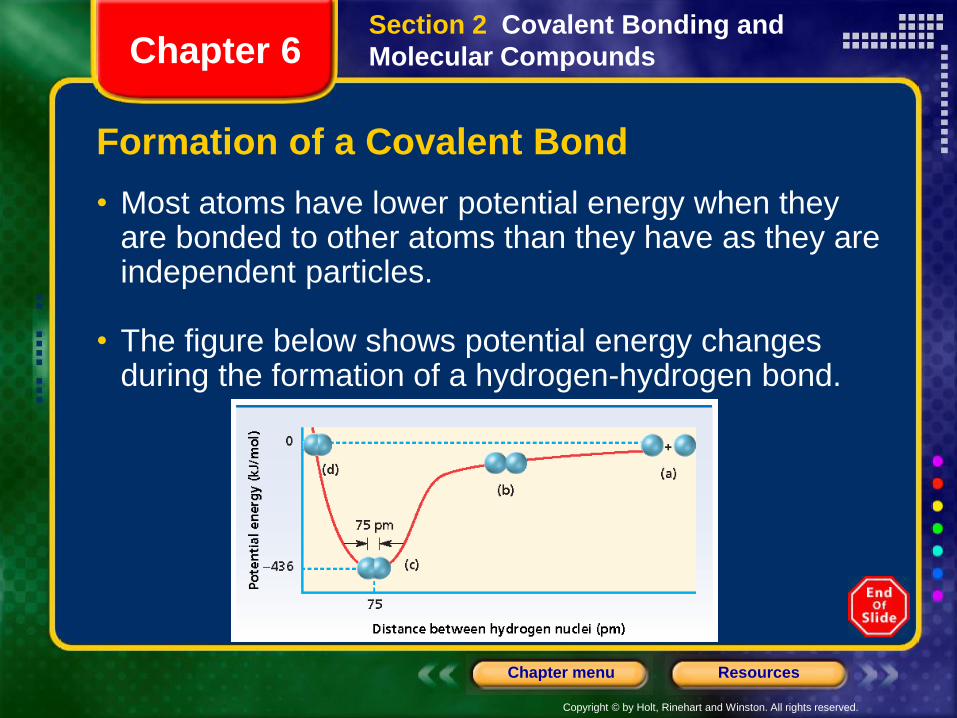
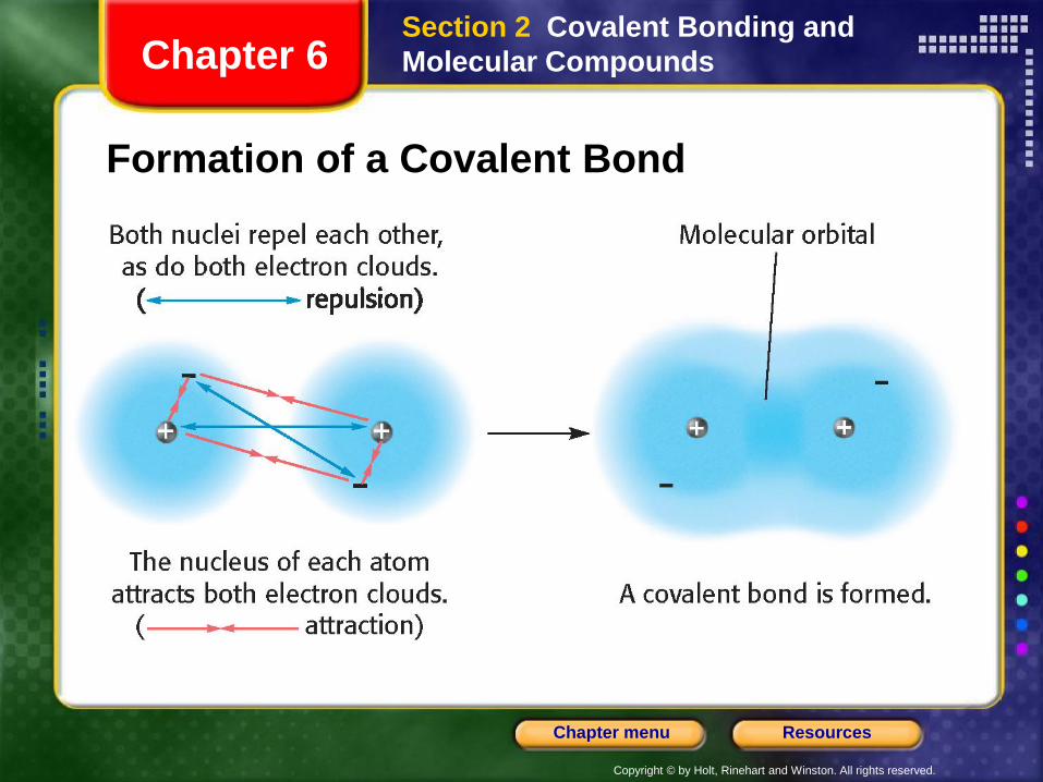
Formation of a Covalent Bond
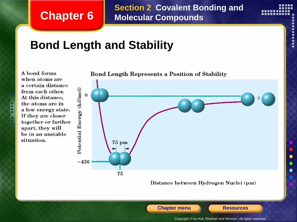
• Most atoms have lower potential energy when they are bonded to other atoms than they have as they are independent particles.
• The figure below shows potential energy changes during the formation of a hydrogen-hydrogen bond.
Section 2 Covalent Bonding and
Molecular CompoundsChapter 6
Copyright © by Holt, Rinehart and Winston. All rights reserved.
ResourcesChapter menu
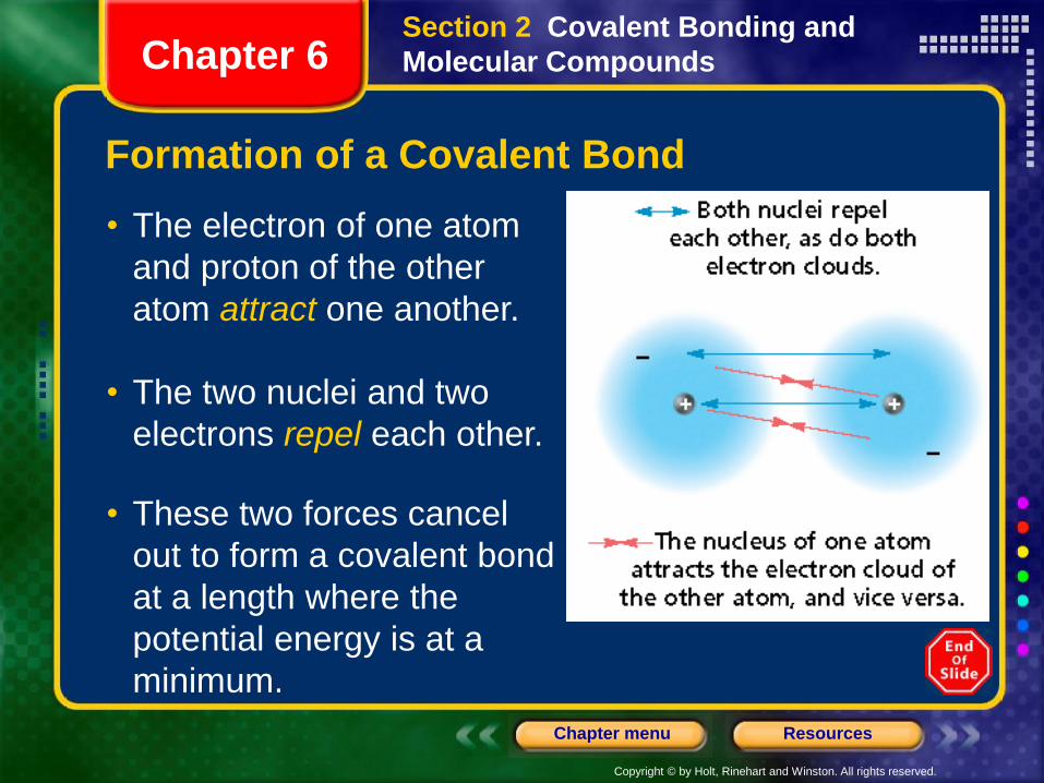
Formation of a Covalent Bond
• The electron of one atom
and proton of the other
atom attract one another.
Section 2 Covalent Bonding and
Molecular CompoundsChapter 6
• The two nuclei and two
electrons repel each other.
• These two forces cancel
out to form a covalent bond
at a length where the
potential energy is at a
minimum.
Copyright © by Holt, Rinehart and Winston. All rights reserved.
ResourcesChapter menu
Formation of a Covalent Bond
Section 2 Covalent Bonding and
Molecular CompoundsChapter 6
Copyright © by Holt, Rinehart and Winston. All rights reserved.
ResourcesChapter menu
Characteristics of the Covalent Bond
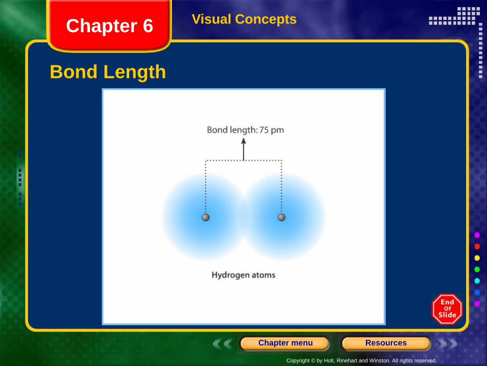
• The distance between two bonded atoms at their
minimum potential energy (the average distance
between two bonded atoms) is the bond length.
• In forming a covalent bond, the hydrogen atoms
release energy. The same amount of energy must be
added to separate the bonded atoms.
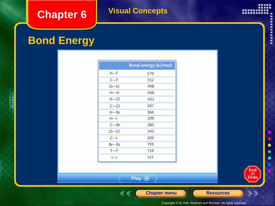
• Bond energy is the energy required to break a
chemical bond and form neutral isolated atoms.
Section 2 Covalent Bonding and
Molecular CompoundsChapter 6
Copyright © by Holt, Rinehart and Winston. All rights reserved.
ResourcesChapter menu
Visual Concepts
Bond Length
Chapter 6
Copyright © by Holt, Rinehart and Winston. All rights reserved.
ResourcesChapter menu
Visual Concepts
Bond Energy
Chapter 6
Copyright © by Holt, Rinehart and Winston. All rights reserved.
ResourcesChapter menu
Bond Length and Stability
Section 2 Covalent Bonding and
Molecular CompoundsChapter 6
Copyright © by Holt, Rinehart and Winston. All rights reserved.
ResourcesChapter menu
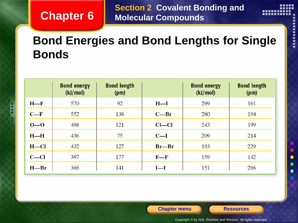
Bond Energies and Bond Lengths for Single
Bonds
Section 2 Covalent Bonding and
Molecular CompoundsChapter 6
Copyright © by Holt, Rinehart and Winston. All rights reserved.
ResourcesChapter menu
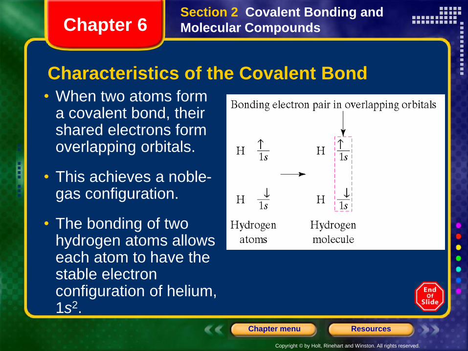
Characteristics of the Covalent Bond
• When two atoms form a covalent bond, their shared electrons form overlapping orbitals.
• This achieves a noble-gas configuration.
• The bonding of two hydrogen atoms allows each atom to have the stable electron configuration of helium, 1s2.
Section 2 Covalent Bonding and
Molecular CompoundsChapter 6
Copyright © by Holt, Rinehart and Winston. All rights reserved.
ResourcesChapter menu
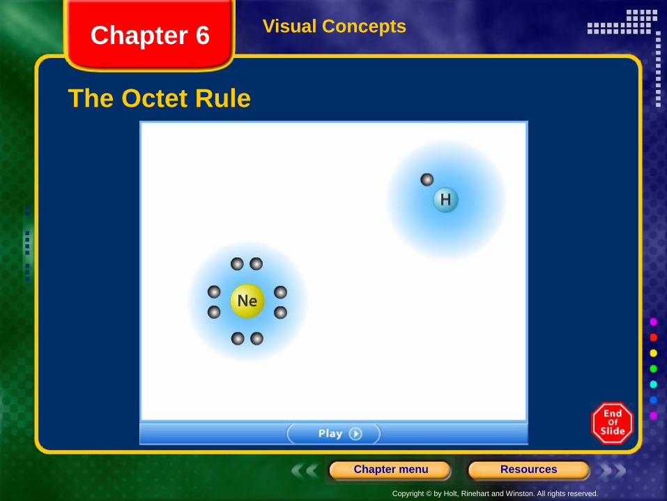
The Octet Rule
• Noble gas atoms are unreactive because their electron configurations are especially stable.
• This stability results from the fact that the noble-gas atoms’ outer s and p orbitals are completely filled by a total of eight electrons.
• Other atoms can fill their outermost s and p orbitals by sharing electrons through covalent bonding.
• Such bond formation follows the octet rule:Chemical compounds tend to form so that each atom, by gaining, losing, or sharing electrons, has an octet of electrons in its highest energy level.
Section 2 Covalent Bonding and
Molecular CompoundsChapter 6
Copyright © by Holt, Rinehart and Winston. All rights reserved.
ResourcesChapter menu
Visual Concepts
The Octet Rule
Chapter 6
Copyright © by Holt, Rinehart and Winston. All rights reserved.
ResourcesChapter menu
The Octet Rule, continuedExceptions to the Octet Rule
• Exceptions to the octet rule include those for atoms that
cannot fit eight electrons, and for those that can fit more
than eight electrons, into their outermost orbital.
• Hydrogen forms bonds in which it is surrounded by only
two electrons.
• Boron has just three valence electrons, so it tends to
form bonds in which it is surrounded by six electrons.
• Main-group elements in Periods 3 and up can form
bonds with expanded valence, involving more than eight
electrons.
Section 2 Covalent Bonding and
Molecular CompoundsChapter 6
Copyright © by Holt, Rinehart and Winston. All rights reserved.
ResourcesChapter menu
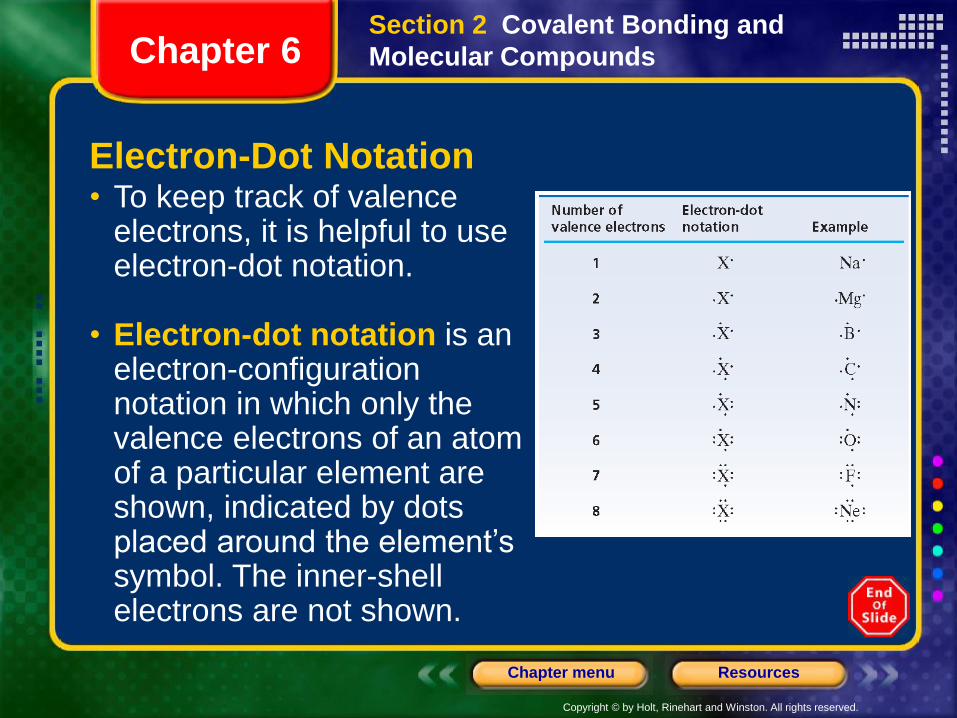
Electron-Dot Notation • To keep track of valence
electrons, it is helpful to use electron-dot notation.
• Electron-dot notation is an electron-configuration notation in which only the valence electrons of an atom of a particular element are shown, indicated by dots placed around the element’s symbol. The inner-shell electrons are not shown.
Section 2 Covalent Bonding and
Molecular CompoundsChapter 6
Copyright © by Holt, Rinehart and Winston. All rights reserved.
ResourcesChapter menu
Electron-Dot Notation, continued
Sample Problem B
a. Write the electron-dot notation for hydrogen.
b. Write the electron-dot notation for nitrogen.
Section 2 Covalent Bonding and
Molecular CompoundsChapter 6
Copyright © by Holt, Rinehart and Winston. All rights reserved.
ResourcesChapter menu
Electron-Dot Notation, continued
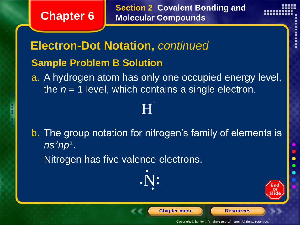
Sample Problem B Solution
a. A hydrogen atom has only one occupied energy level,
the n = 1 level, which contains a single electron.
H
N
Section 2 Covalent Bonding and
Molecular CompoundsChapter 6
b. The group notation for nitrogen’s family of elements is
ns2np3.
Nitrogen has five valence electrons.
Copyright © by Holt, Rinehart and Winston. All rights reserved.
ResourcesChapter menu
Lewis Structures
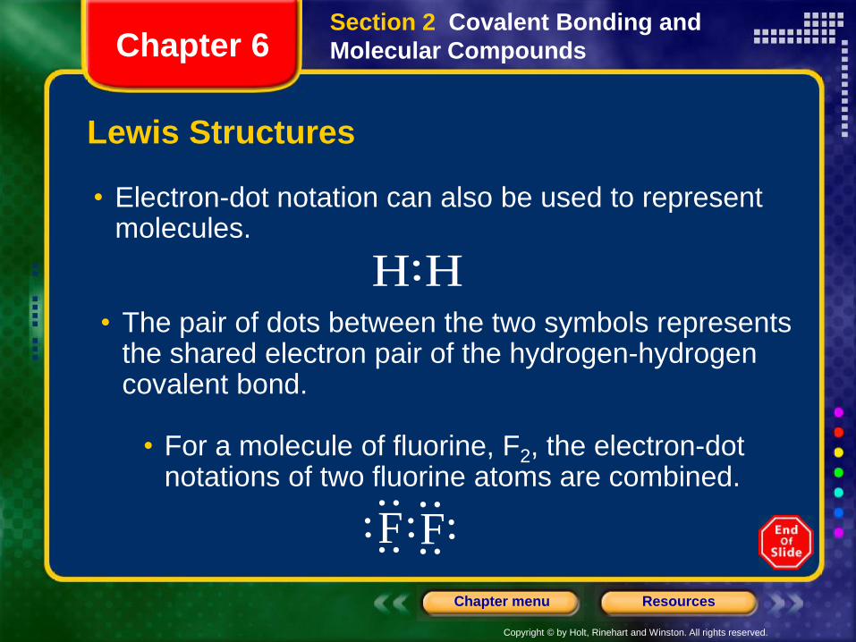
• Electron-dot notation can also be used to represent molecules.
F F
H H
Section 2 Covalent Bonding and
Molecular CompoundsChapter 6
• The pair of dots between the two symbols represents the shared electron pair of the hydrogen-hydrogen covalent bond.
• For a molecule of fluorine, F2, the electron-dot notations of two fluorine atoms are combined.
Copyright © by Holt, Rinehart and Winston. All rights reserved.
ResourcesChapter menu
Lewis Structures
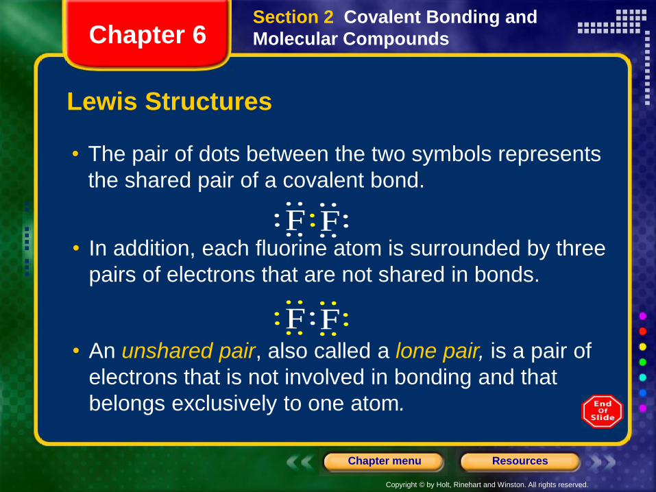
• The pair of dots between the two symbols represents
the shared pair of a covalent bond.
F F
F F
Section 2 Covalent Bonding and
Molecular CompoundsChapter 6
• In addition, each fluorine atom is surrounded by three
pairs of electrons that are not shared in bonds.
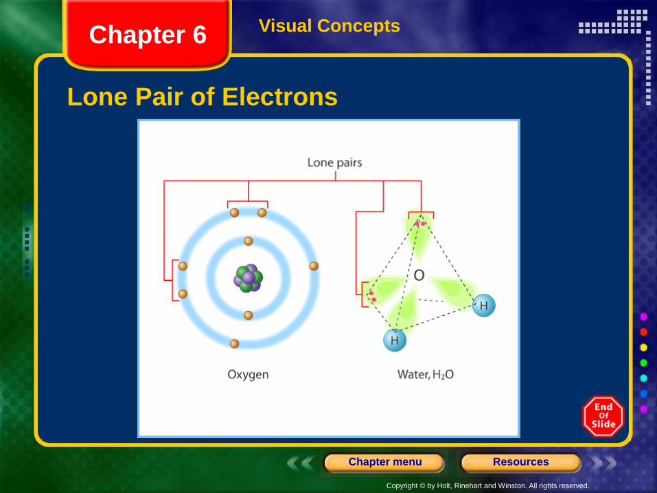
• An unshared pair, also called a lone pair, is a pair of
electrons that is not involved in bonding and that
belongs exclusively to one atom.
Copyright © by Holt, Rinehart and Winston. All rights reserved.
ResourcesChapter menu
Visual Concepts
Lewis Structures
Chapter 6
Copyright © by Holt, Rinehart and Winston. All rights reserved.
ResourcesChapter menu
Visual Concepts
Lone Pair of Electrons
Chapter 6
Copyright © by Holt, Rinehart and Winston. All rights reserved.
ResourcesChapter menu
Lewis Structures
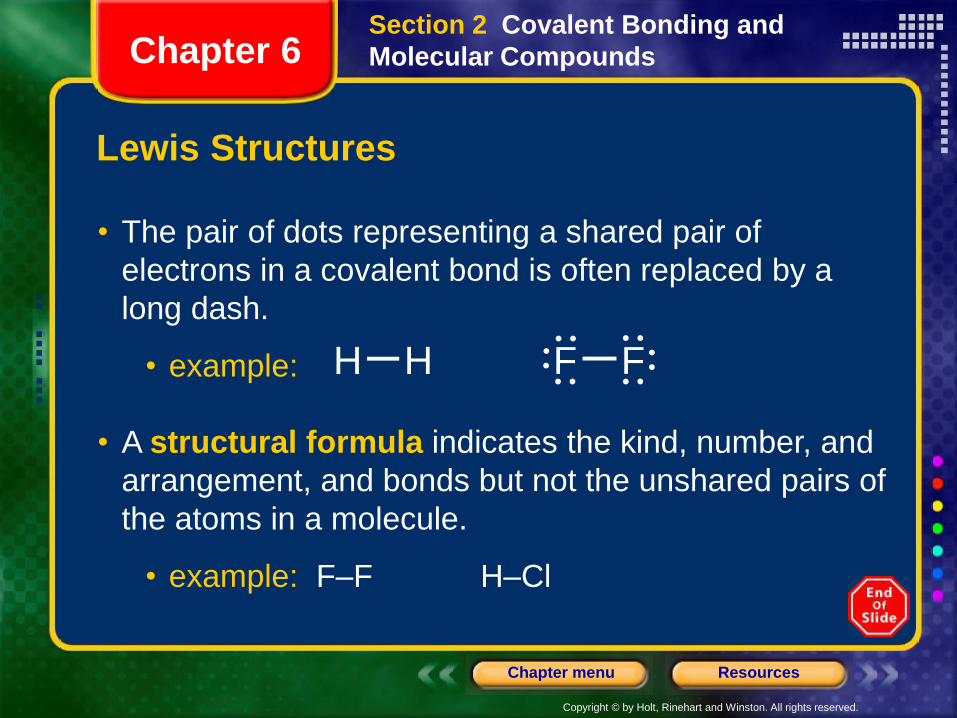
• The pair of dots representing a shared pair of
electrons in a covalent bond is often replaced by a
long dash.
• example: H H F F
Section 2 Covalent Bonding and
Molecular CompoundsChapter 6
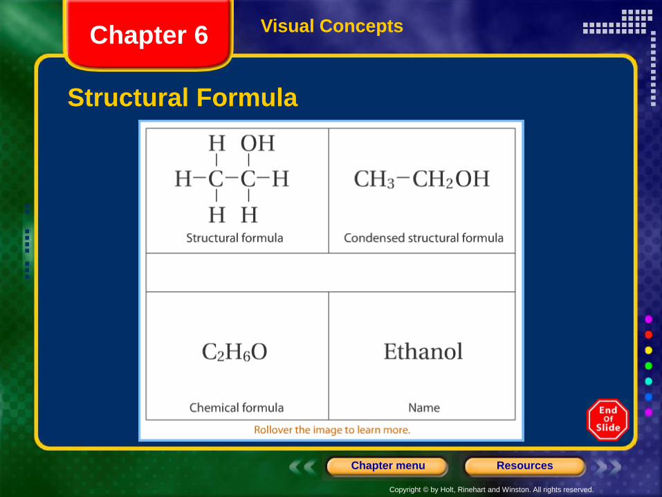
• A structural formula indicates the kind, number, and
arrangement, and bonds but not the unshared pairs of
the atoms in a molecule.
• example: F–F H–Cl
Copyright © by Holt, Rinehart and Winston. All rights reserved.
ResourcesChapter menu
Visual Concepts
Structural Formula
Chapter 6
Copyright © by Holt, Rinehart and Winston. All rights reserved.
ResourcesChapter menu
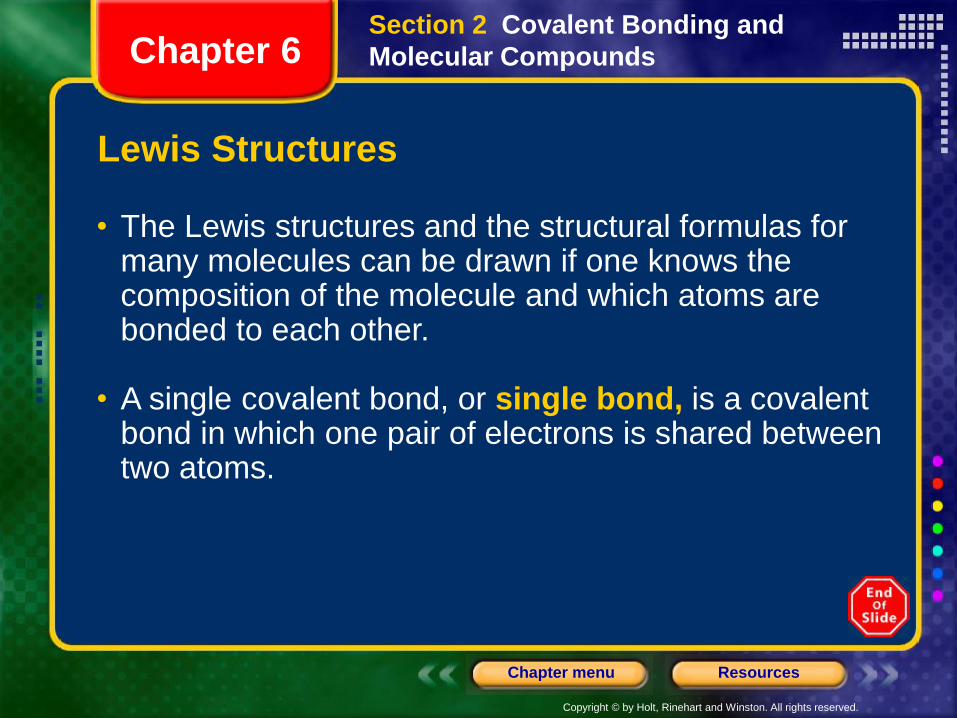
• The Lewis structures and the structural formulas for many molecules can be drawn if one knows the composition of the molecule and which atoms are bonded to each other.
• A single covalent bond, or single bond, is a covalent bond in which one pair of electrons is shared between two atoms.
Section 2 Covalent Bonding and
Molecular CompoundsChapter 6
Lewis Structures
Copyright © by Holt, Rinehart and Winston. All rights reserved.
ResourcesChapter menu
Lewis Structures, continued
Sample Problem C
Draw the Lewis structure of iodomethane, CH3I.
Section 2 Covalent Bonding and
Molecular CompoundsChapter 6
Copyright © by Holt, Rinehart and Winston. All rights reserved.
ResourcesChapter menu
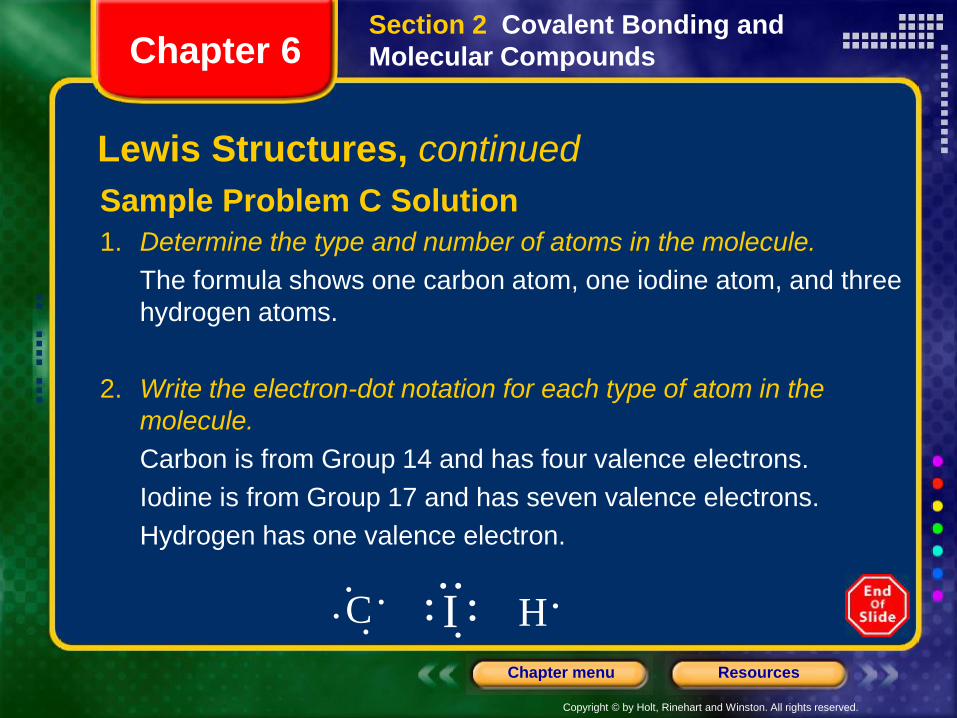
Sample Problem C Solution
1. Determine the type and number of atoms in the molecule.
The formula shows one carbon atom, one iodine atom, and three
hydrogen atoms.
2. Write the electron-dot notation for each type of atom in the
molecule.
Carbon is from Group 14 and has four valence electrons.
Iodine is from Group 17 and has seven valence electrons.
Hydrogen has one valence electron.
C I H
Section 2 Covalent Bonding and
Molecular CompoundsChapter 6
Lewis Structures, continued
Copyright © by Holt, Rinehart and Winston. All rights reserved.
ResourcesChapter menu
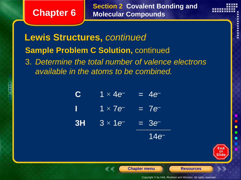
Sample Problem C Solution, continued
3. Determine the total number of valence electrons
available in the atoms to be combined.
C 1 × 4e– = 4e–
I 1 × 7e– = 7e–
3H 3 × 1e– = 3e–
14e–
Section 2 Covalent Bonding and
Molecular CompoundsChapter 6
Lewis Structures, continued
Copyright © by Holt, Rinehart and Winston. All rights reserved.
ResourcesChapter menu
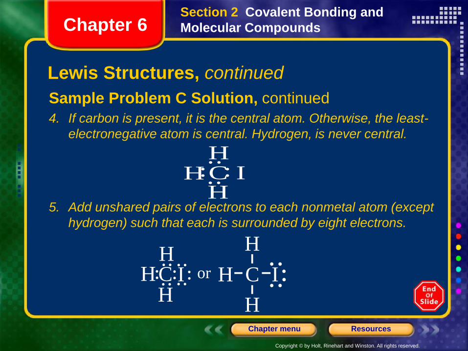
Sample Problem C Solution, continued
4. If carbon is present, it is the central atom. Otherwise, the least-
electronegative atom is central. Hydrogen, is never central.
CHH
HI
HC IH
Hor H C
H
I
H
Section 2 Covalent Bonding and
Molecular CompoundsChapter 6
Lewis Structures, continued
5. Add unshared pairs of electrons to each nonmetal atom (except
hydrogen) such that each is surrounded by eight electrons.
Copyright © by Holt, Rinehart and Winston. All rights reserved.
ResourcesChapter menu
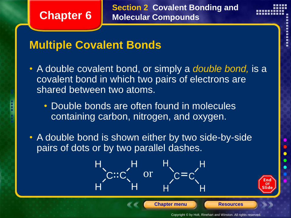
Multiple Covalent Bonds
• A double covalent bond, or simply a double bond, is a covalent bond in which two pairs of electrons are shared between two atoms.
• Double bonds are often found in molecules containing carbon, nitrogen, and oxygen.
• A double bond is shown either by two side-by-side pairs of dots or by two parallel dashes.
H
CH H
C
Hor
H
C
H
C
H
H
Section 2 Covalent Bonding and
Molecular CompoundsChapter 6
Copyright © by Holt, Rinehart and Winston. All rights reserved.
ResourcesChapter menu
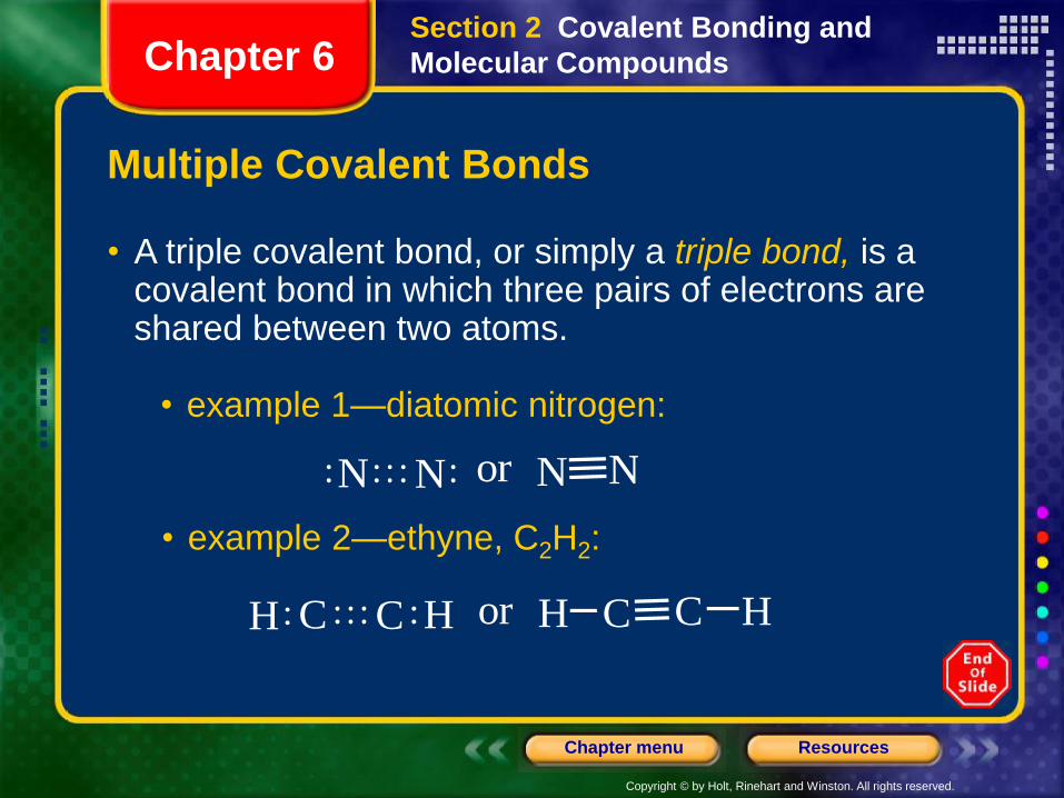
Multiple Covalent Bonds
• A triple covalent bond, or simply a triple bond, is a covalent bond in which three pairs of electrons are shared between two atoms.
• example 1—diatomic nitrogen:
N N or N N
C C or C CH H H H
Section 2 Covalent Bonding and
Molecular CompoundsChapter 6
• example 2—ethyne, C2H2:
Copyright © by Holt, Rinehart and Winston. All rights reserved.
ResourcesChapter menu
Multiple Covalent Bonds
• Double and triple bonds are referred to as multiple
bonds, or multiple covalent bonds.
• In general, double bonds have greater bond energies and
are shorter than single bonds.
• Triple bonds are even stronger and shorter than
double bonds.
• When writing Lewis structures for molecules that
contain carbon, nitrogen, or oxygen, remember that
multiple bonds between pairs of these atoms
are possible.
Section 2 Covalent Bonding and
Molecular CompoundsChapter 6
Copyright © by Holt, Rinehart and Winston. All rights reserved.
ResourcesChapter menu
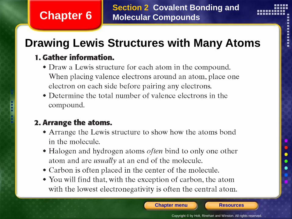
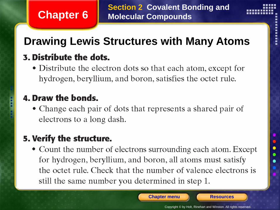
Drawing Lewis Structures with Many Atoms
Section 2 Covalent Bonding and
Molecular CompoundsChapter 6
Copyright © by Holt, Rinehart and Winston. All rights reserved.
ResourcesChapter menu
Drawing Lewis Structures with Many Atoms
Section 2 Covalent Bonding and
Molecular CompoundsChapter 6
Copyright © by Holt, Rinehart and Winston. All rights reserved.
ResourcesChapter menu
Multiple Covalent Bonds, continued
Sample Problem D
Draw the Lewis structure for methanal, CH2O, which is
also known as formaldehyde.
Section 2 Covalent Bonding and
Molecular CompoundsChapter 6
Copyright © by Holt, Rinehart and Winston. All rights reserved.
ResourcesChapter menu
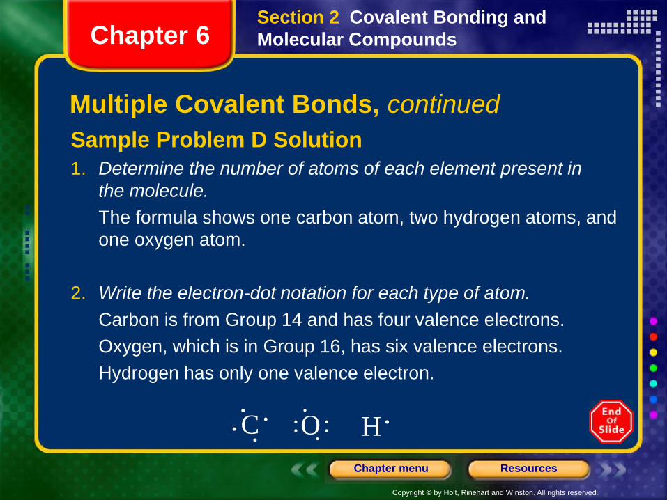
Sample Problem D Solution
1. Determine the number of atoms of each element present in
the molecule.
The formula shows one carbon atom, two hydrogen atoms, and
one oxygen atom.
2. Write the electron-dot notation for each type of atom.
Carbon is from Group 14 and has four valence electrons.
Oxygen, which is in Group 16, has six valence electrons.
Hydrogen has only one valence electron.
C HO
Section 2 Covalent Bonding and
Molecular CompoundsChapter 6
Multiple Covalent Bonds, continued
Copyright © by Holt, Rinehart and Winston. All rights reserved.
ResourcesChapter menu
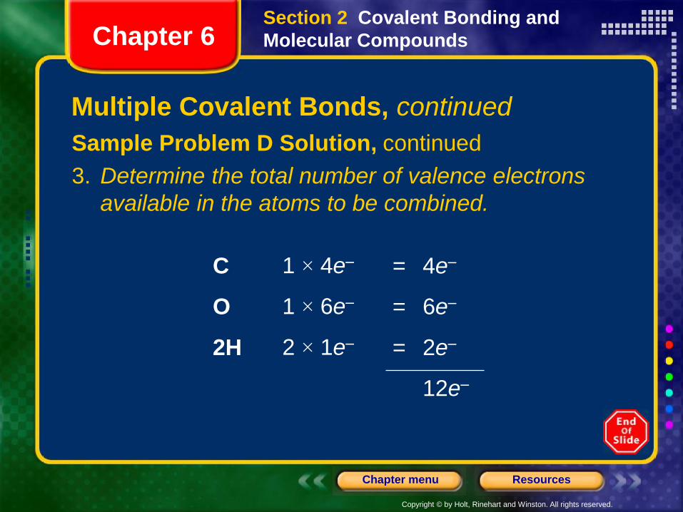
Sample Problem D Solution, continued
3. Determine the total number of valence electrons
available in the atoms to be combined.
C 1 × 4e– = 4e–
O 1 × 6e– = 6e–
2H 2 × 1e– = 2e–
12e–
Section 2 Covalent Bonding and
Molecular CompoundsChapter 6
Multiple Covalent Bonds, continued
Copyright © by Holt, Rinehart and Winston. All rights reserved.
ResourcesChapter menu
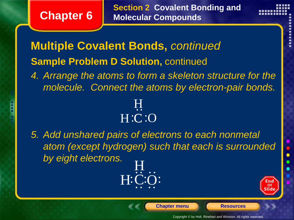
Sample Problem D Solution, continued
4. Arrange the atoms to form a skeleton structure for the
molecule. Connect the atoms by electron-pair bonds.
5. Add unshared pairs of electrons to each nonmetal
atom (except hydrogen) such that each is surrounded
by eight electrons.
CCH C OH
H C OH
Section 2 Covalent Bonding and
Molecular CompoundsChapter 6
Multiple Covalent Bonds, continued
Copyright © by Holt, Rinehart and Winston. All rights reserved.
ResourcesChapter menu
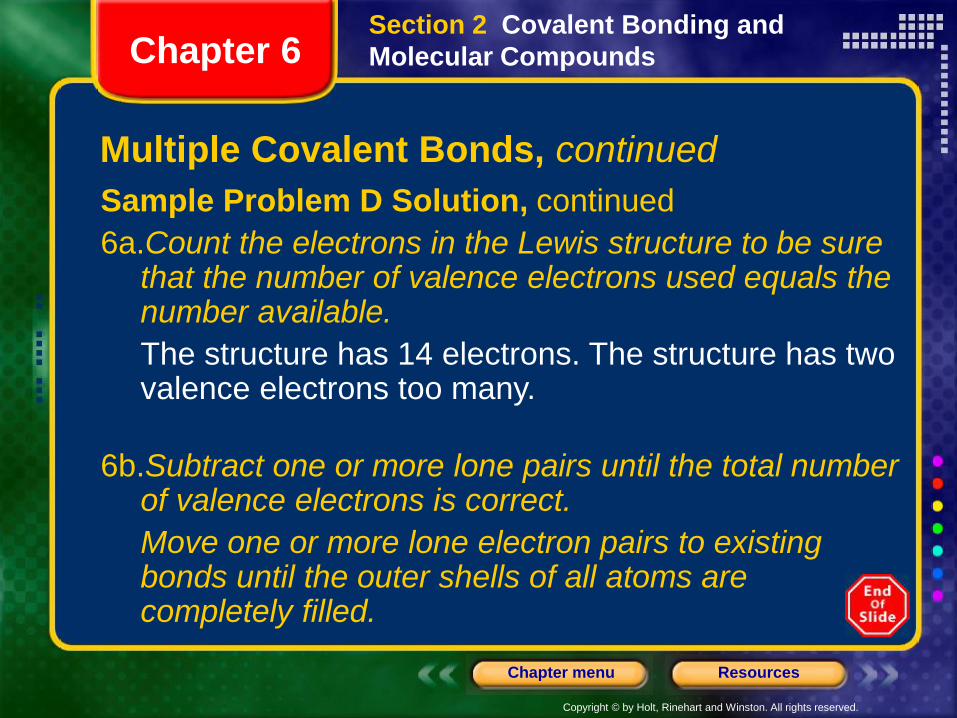
Sample Problem D Solution, continued
6a.Count the electrons in the Lewis structure to be sure that the number of valence electrons used equals the number available.
The structure has 14 electrons. The structure has two valence electrons too many.
6b.Subtract one or more lone pairs until the total number of valence electrons is correct.
Move one or more lone electron pairs to existing bonds until the outer shells of all atoms are completely filled.
Section 2 Covalent Bonding and
Molecular CompoundsChapter 6
Multiple Covalent Bonds, continued
Copyright © by Holt, Rinehart and Winston. All rights reserved.
ResourcesChapter menu
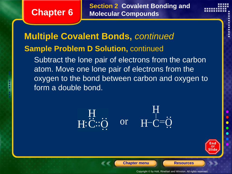
Sample Problem D Solution, continued
Subtract the lone pair of electrons from the carbon
atom. Move one lone pair of electrons from the
oxygen to the bond between carbon and oxygen to
form a double bond.
H C OH
H C O
Hor
Section 2 Covalent Bonding and
Molecular CompoundsChapter 6
Multiple Covalent Bonds, continued
Copyright © by Holt, Rinehart and Winston. All rights reserved.
ResourcesChapter menu
Objectives
• Compare a chemical formula for a molecular
compounds with one for an ionic compound.
• Discuss the arrangements of ions in crystals.
• Define lattice energy and explain its significance.
• List and compare the distinctive properties of ionic
and molecular compounds.
• Write the Lewis structure for a polyatomic ion given
the identity of the atoms combined and other
appropriate information.
Section 3 Ionic Bonding and
Ionic CompoundsChapter 6
Copyright © by Holt, Rinehart and Winston. All rights reserved.
ResourcesChapter menu
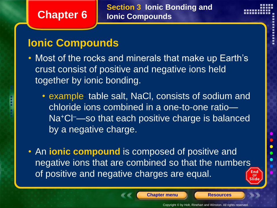
Ionic Compounds
• Most of the rocks and minerals that make up Earth’s
crust consist of positive and negative ions held
together by ionic bonding.
• example: table salt, NaCl, consists of sodium and
chloride ions combined in a one-to-one ratio—
Na+Cl–—so that each positive charge is balanced
by a negative charge.
• An ionic compound is composed of positive and
negative ions that are combined so that the numbers
of positive and negative charges are equal.
Section 3 Ionic Bonding and
Ionic CompoundsChapter 6
Copyright © by Holt, Rinehart and Winston. All rights reserved.
ResourcesChapter menu
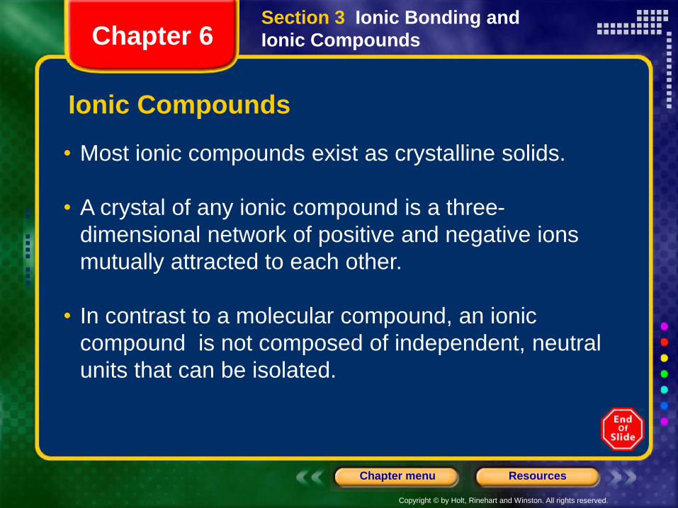
Ionic Compounds
• Most ionic compounds exist as crystalline solids.
• A crystal of any ionic compound is a three-
dimensional network of positive and negative ions
mutually attracted to each other.
• In contrast to a molecular compound, an ionic
compound is not composed of independent, neutral
units that can be isolated.
Section 3 Ionic Bonding and
Ionic CompoundsChapter 6
Copyright © by Holt, Rinehart and Winston. All rights reserved.
ResourcesChapter menu
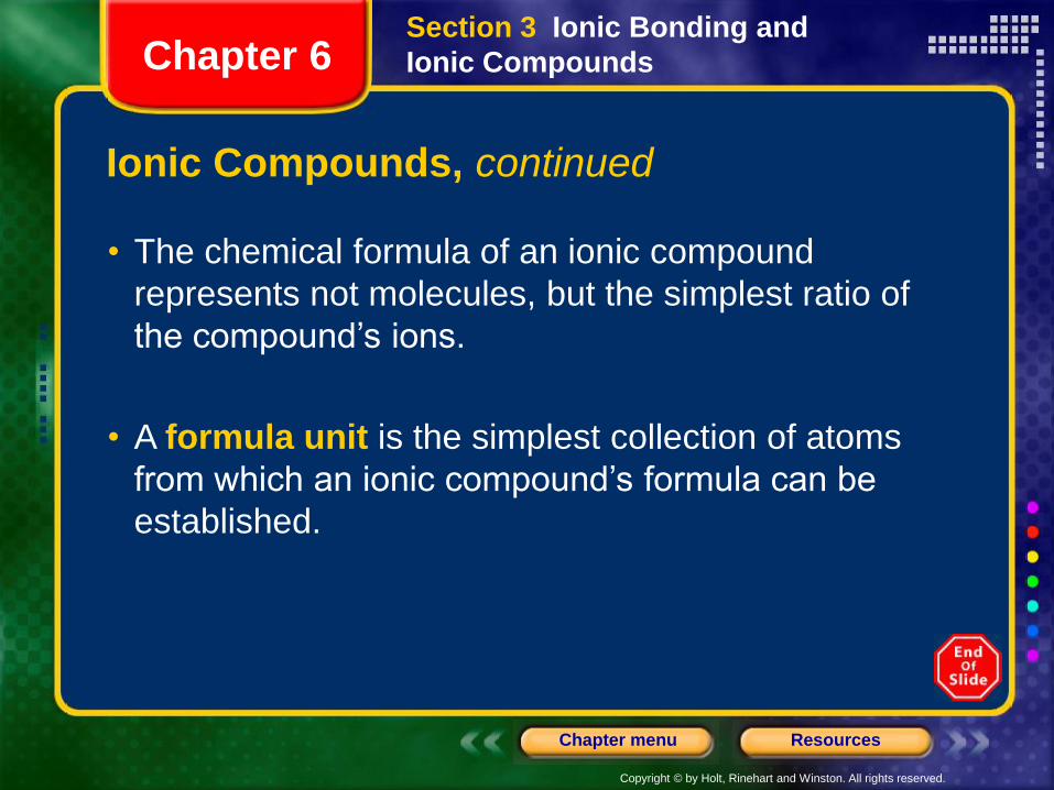
Ionic Compounds, continued
• The chemical formula of an ionic compound
represents not molecules, but the simplest ratio of
the compound’s ions.
• A formula unit is the simplest collection of atoms
from which an ionic compound’s formula can be
established.
Section 3 Ionic Bonding and
Ionic CompoundsChapter 6
Copyright © by Holt, Rinehart and Winston. All rights reserved.
ResourcesChapter menu
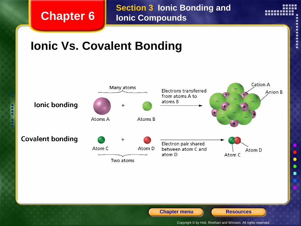
Ionic Vs. Covalent Bonding
Section 3 Ionic Bonding and
Ionic CompoundsChapter 6
Copyright © by Holt, Rinehart and Winston. All rights reserved.
ResourcesChapter menu
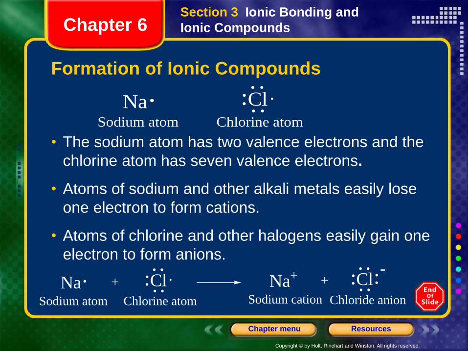
Formation of Ionic Compounds
• The sodium atom has two valence electrons and the
chlorine atom has seven valence electrons.
• Atoms of sodium and other alkali metals easily lose
one electron to form cations.
• Atoms of chlorine and other halogens easily gain one
electron to form anions.
Na ClSodium atom Chlorine atom
Na ClSodium atom Chlorine atom
+ Na+
Sodium cation
ClChloride anion
+-
Section 3 Ionic Bonding and
Ionic CompoundsChapter 6
Copyright © by Holt, Rinehart and Winston. All rights reserved.
ResourcesChapter menu
Formation of Ionic Compounds, continued
• In an ionic crystal, ions minimize their potential energy by combining in an orderly arrangement known as a crystal lattice.
• Attractive forces exist between oppositely charged ions within the lattice.
• Repulsive forces exist between like-charged ions within the lattice.
• The combined attractive and repulsive forces within a crystal lattice determine:
• the distances between ions
• the pattern of the ions’ arrangement in the crystal
Section 3 Ionic Bonding and
Ionic CompoundsChapter 6
Copyright © by Holt, Rinehart and Winston. All rights reserved.
ResourcesChapter menu
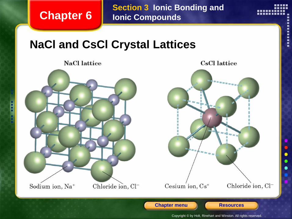
NaCl and CsCl Crystal Lattices
Section 3 Ionic Bonding and
Ionic CompoundsChapter 6
Copyright © by Holt, Rinehart and Winston. All rights reserved.
ResourcesChapter menu
Visual Concepts
Lattice Energy
Chapter 6
Copyright © by Holt, Rinehart and Winston. All rights reserved.
ResourcesChapter menu
A Comparison of Ionic and Molecular
Compounds
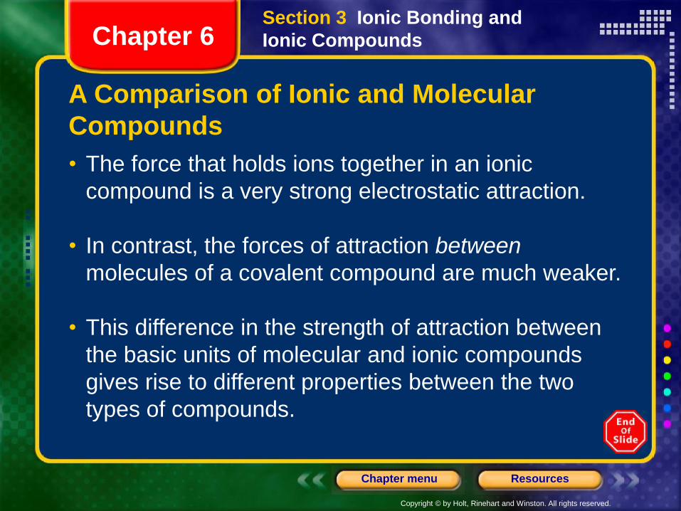
• The force that holds ions together in an ionic
compound is a very strong electrostatic attraction.
• In contrast, the forces of attraction between
molecules of a covalent compound are much weaker.
• This difference in the strength of attraction between
the basic units of molecular and ionic compounds
gives rise to different properties between the two
types of compounds.
Section 3 Ionic Bonding and
Ionic CompoundsChapter 6
Copyright © by Holt, Rinehart and Winston. All rights reserved.
ResourcesChapter menu
A Comparison of Ionic and Molecular
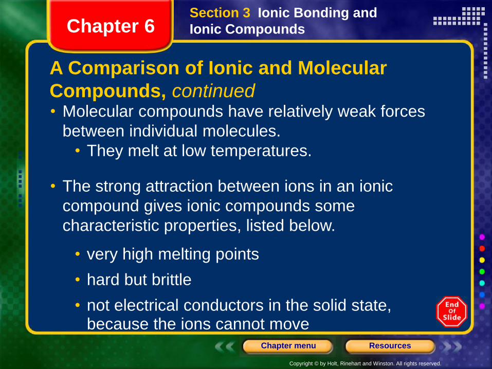
Compounds, continued• Molecular compounds have relatively weak forces
between individual molecules.
• They melt at low temperatures.
• The strong attraction between ions in an ionic
compound gives ionic compounds some
characteristic properties, listed below.
• very high melting points
• hard but brittle
• not electrical conductors in the solid state, because the ions cannot move
Section 3 Ionic Bonding and
Ionic CompoundsChapter 6
Copyright © by Holt, Rinehart and Winston. All rights reserved.
ResourcesChapter menu
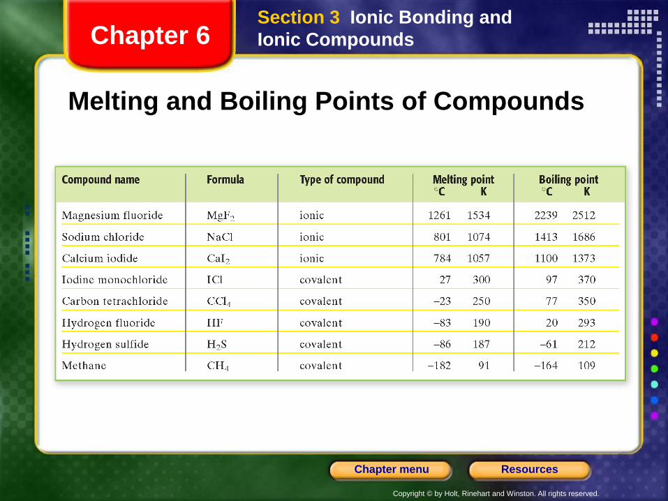
Melting and Boiling Points of Compounds
Section 3 Ionic Bonding and
Ionic CompoundsChapter 6
Copyright © by Holt, Rinehart and Winston. All rights reserved.
ResourcesChapter menu
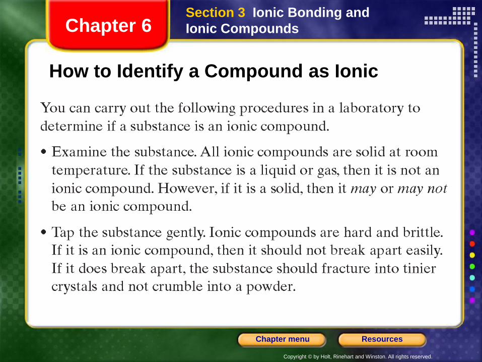
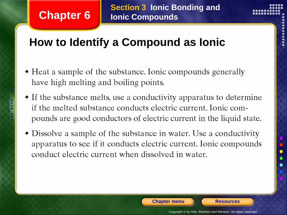
How to Identify a Compound as Ionic
Section 3 Ionic Bonding and
Ionic CompoundsChapter 6
Copyright © by Holt, Rinehart and Winston. All rights reserved.
ResourcesChapter menu
Section 3 Ionic Bonding and
Ionic CompoundsChapter 6
How to Identify a Compound as Ionic
Copyright © by Holt, Rinehart and Winston. All rights reserved.
ResourcesChapter menu
Polyatomic Ions
• Certain atoms bond covalently with each other to form
a group of atoms that has both molecular and ionic
characteristics.
• A charged group of covalently bonded atoms is
known as a polyatomic ion.
• Like other ions, polyatomic ions have a charge that
results from either a shortage or excess of electrons.
Section 3 Ionic Bonding and
Ionic CompoundsChapter 6
Copyright © by Holt, Rinehart and Winston. All rights reserved.
ResourcesChapter menu
Polyatomic Ions
• An example of a polyatomic ion is the ammonium
ion: . It is sometimes written as to show
that the group of atoms as a whole has a charge of
1+.
+
4NH+
4[NH ]
Section 3 Ionic Bonding and
Ionic CompoundsChapter 6
• The charge of the ammonium ion is determined
as follows:
• The seven protons in the nitrogen atom plus the four protons in the four hydrogen atoms give the ammonium ion a total positive charge of 11+.
Copyright © by Holt, Rinehart and Winston. All rights reserved.
ResourcesChapter menu
Polyatomic Ions, continued
• The charge of the ammonium ion is determined as follows, continued:
• When nitrogen and hydrogen atoms combine to form an ammonium ion, one of their electrons is lost, giving the polyatomic ion a total negative charge of 10–.
• The total charge is therefore (11+) + (10–) = 1+.
Section 3 Ionic Bonding and
Ionic CompoundsChapter 6
Copyright © by Holt, Rinehart and Winston. All rights reserved.
ResourcesChapter menu
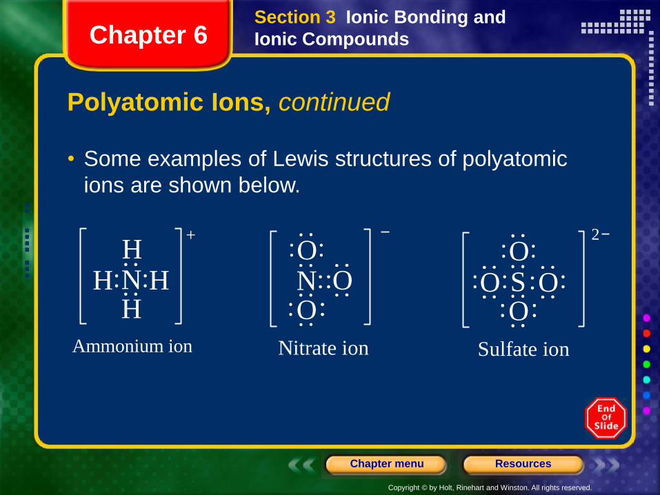
• Some examples of Lewis structures of polyatomic
ions are shown below.
N HH
HH
+
N OO
O
Ammonium ion Nitrate ion
S OO
O
Sulfate ion
2
O
Section 3 Ionic Bonding and
Ionic CompoundsChapter 6
Polyatomic Ions, continued
Copyright © by Holt, Rinehart and Winston. All rights reserved.
ResourcesChapter menu
Visual Concepts
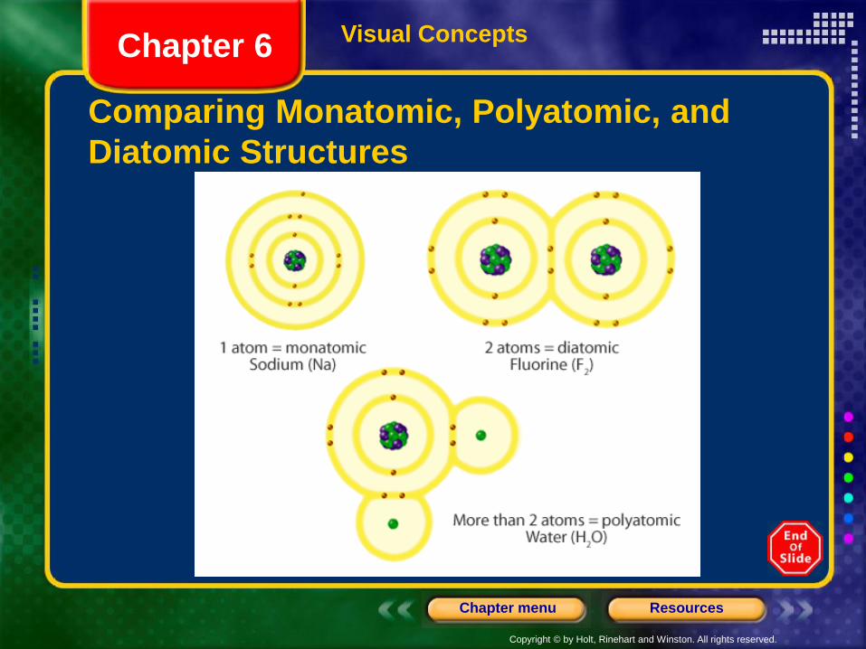
Comparing Monatomic, Polyatomic, and
Diatomic Structures
Chapter 6
Copyright © by Holt, Rinehart and Winston. All rights reserved.
ResourcesChapter menu
Objectives
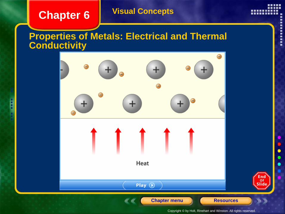
• Describe the electron-sea model of metallic bonding,
and explain why metals are good electrical
conductors.
• Explain why metal surfaces are shiny.
• Explain why metals are malleable and ductile but
ionic-crystalline compound are not.
Section 4 Metallic BondingChapter 6
Copyright © by Holt, Rinehart and Winston. All rights reserved.
ResourcesChapter menu
Metallic Bonding
• Chemical bonding is different in metals than it is in
ionic, molecular, or covalent-network compounds.
• The unique characteristics of metallic bonding gives
metals their characteristic properties, listed below.
• electrical conductivity
• thermal conductivity
• malleability
• ductility
• shiny appearance
Section 4 Metallic BondingChapter 6
Copyright © by Holt, Rinehart and Winston. All rights reserved.
ResourcesChapter menu
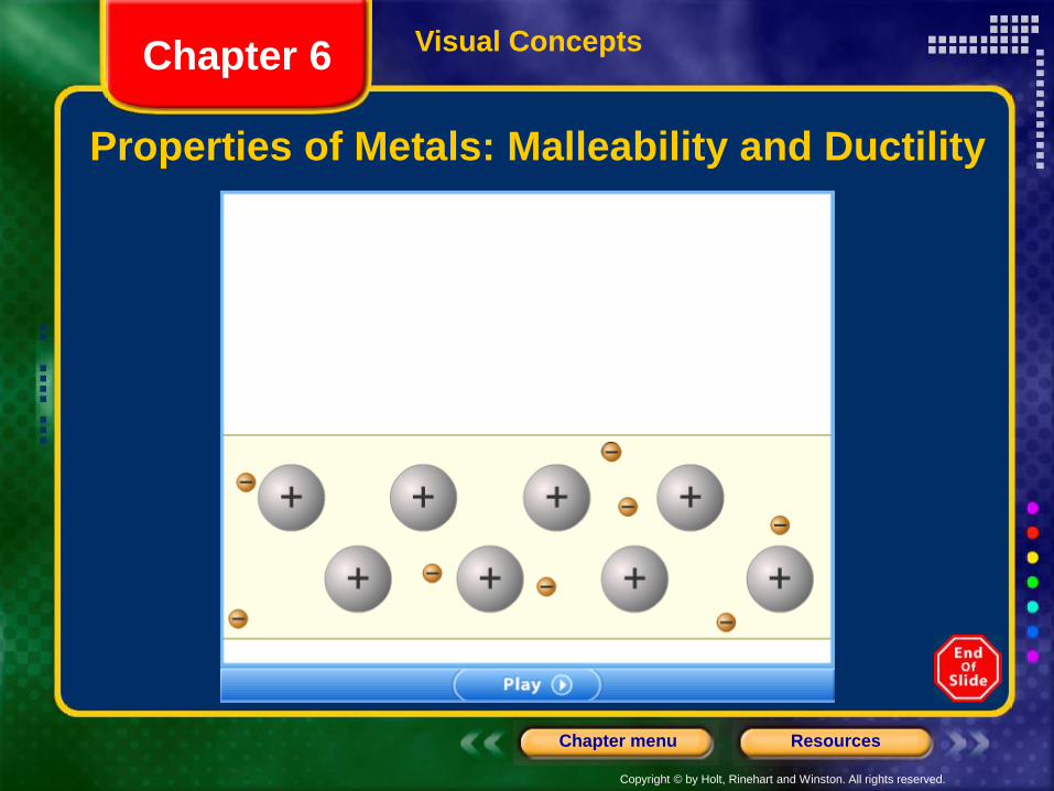
Metallic Bonding, continued
• Malleability is the ability of a substance to be
hammered or beaten into thin sheets.
• Ductility is the ability of a substance to be drawn,
pulled, or extruded through a small opening to
produce a wire.
Section 4 Metallic BondingChapter 6
Copyright © by Holt, Rinehart and Winston. All rights reserved.
ResourcesChapter menu
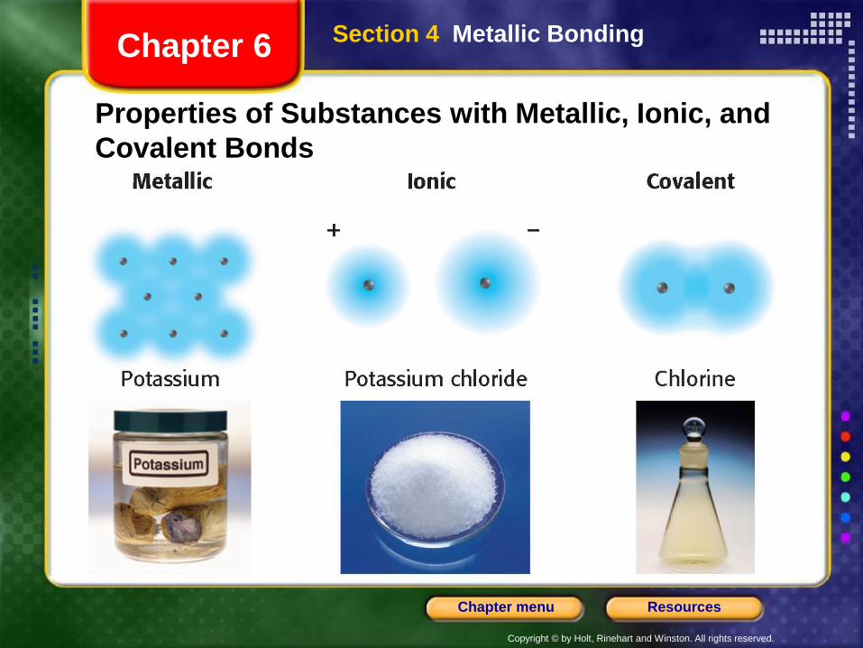
Properties of Substances with Metallic, Ionic, and
Covalent Bonds
Section 4 Metallic BondingChapter 6
Copyright © by Holt, Rinehart and Winston. All rights reserved.
ResourcesChapter menu
The Metallic-Bond Model
• In a metal, the vacant orbitals in the atoms’ outer
energy levels overlap.
• This overlapping of orbitals allows the outer electrons
of the atoms to roam freely throughout the entire metal.
• The electrons are delocalized, which means that they
do not belong to any one atom but move freely about
the metal’s network of empty atomic orbitals.
• These mobile electrons form a sea of electrons around
the metal atoms, which are packed together in a
crystal lattice.
Section 4 Metallic BondingChapter 6
Copyright © by Holt, Rinehart and Winston. All rights reserved.
ResourcesChapter menu
The Metallic-Bond Model, continued
• The chemical bonding that results from the attraction
between metal atoms and the surrounding sea of
electrons is called metallic bonding.
Section 4 Metallic BondingChapter 6
Copyright © by Holt, Rinehart and Winston. All rights reserved.
ResourcesChapter menu
Visual Concepts
Properties of Metals: Malleability and Ductility
Chapter 6
Copyright © by Holt, Rinehart and Winston. All rights reserved.
ResourcesChapter menu
Visual Concepts
Properties of Metals: Electrical and Thermal Conductivity
Chapter 6
Copyright © by Holt, Rinehart and Winston. All rights reserved.
ResourcesChapter menu
Objectives
• Explain VSEPR theory.
• Predict the shapes of molecules or polyatomic ions
using VSEPR theory.
• Explain how the shapes of molecules are accounted
for by hybridization theory.
Section 5 Molecular GeometryChapter 6
Copyright © by Holt, Rinehart and Winston. All rights reserved.
ResourcesChapter menu
Objectives, continued
• Describe dipole-dipole forces, hydrogen bonding,
induced dipoles, and London dispersion forces and
their effects on properties such as boiling and
melting points.
• Explain the shapes of molecules or polyatomic ions
using VSEPR theory.
Section 5 Molecular GeometryChapter 6
Copyright © by Holt, Rinehart and Winston. All rights reserved.
ResourcesChapter menu
Molecular Geometry
• The properties of molecules depend not only on the bonding
of atoms but also on molecular geometry: the three-
dimensional arrangement of a molecule’s atoms.
• The polarity of each bond, along with the geometry of the
molecule, determines molecular polarity, or the uneven
distribution of molecular shape.
• Molecular polarity strongly influences the forces that act
between molecules in liquids and solids.
• A chemical formula, by itself, reveals little information about
a molecule’s geometry.
Section 5 Molecular GeometryChapter 6
Copyright © by Holt, Rinehart and Winston. All rights reserved.
ResourcesChapter menu
VSEPR Theory
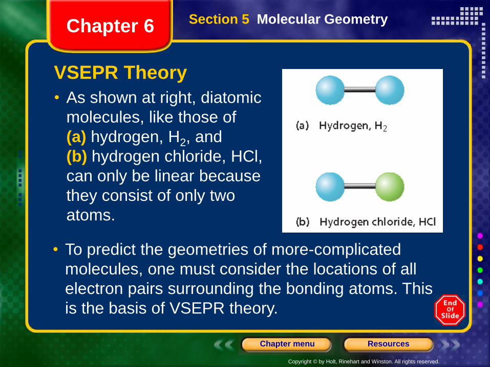
• As shown at right, diatomic
molecules, like those of
(a) hydrogen, H2, and
(b) hydrogen chloride, HCl,
can only be linear because
they consist of only two
atoms.
• To predict the geometries of more-complicated
molecules, one must consider the locations of all
electron pairs surrounding the bonding atoms. This
is the basis of VSEPR theory.
Section 5 Molecular GeometryChapter 6
Copyright © by Holt, Rinehart and Winston. All rights reserved.
ResourcesChapter menu
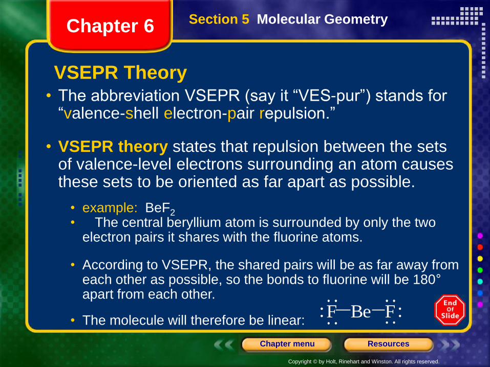
VSEPR Theory• The abbreviation VSEPR (say it “VES-pur”) stands for
“valence-shell electron-pair repulsion.”
• VSEPR theory states that repulsion between the sets of valence-level electrons surrounding an atom causes these sets to be oriented as far apart as possible.
• example: BeF2
• The central beryllium atom is surrounded by only the two electron pairs it shares with the fluorine atoms.
• According to VSEPR, the shared pairs will be as far away from each other as possible, so the bonds to fluorine will be 180°apart from each other.
• The molecule will therefore be linear:BeF F
Section 5 Molecular GeometryChapter 6
Copyright © by Holt, Rinehart and Winston. All rights reserved.
ResourcesChapter menu
VSEPR Theory
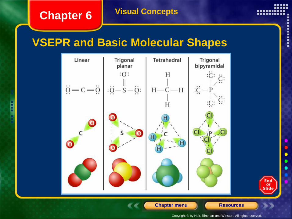
• Representing the central atom in a molecule by A and the atoms bonded to the central atom by B, then according to VSEPR theory, BeF2 is an example of an AB2 molecule, which is linear.
• In an AB3 molecule, the three A–B bonds stay farthest apart by pointing to the corners of an equilateral triangle, giving 120° angles between the bonds.
• In an AB4 molecule, the distance between electron pairs is maximized if each A–B bond points to one of four corners of a tetrahedron.
Section 5 Molecular GeometryChapter 6
Copyright © by Holt, Rinehart and Winston. All rights reserved.
ResourcesChapter menu
Visual Concepts
VSEPR and Basic Molecular Shapes
Chapter 6
Copyright © by Holt, Rinehart and Winston. All rights reserved.
ResourcesChapter menu
VSEPR Theory, continued
Sample Problem E
Use VSEPR theory to predict the molecular geometry of
boron trichloride, BCl3.
Section 5 Molecular GeometryChapter 6
Copyright © by Holt, Rinehart and Winston. All rights reserved.
ResourcesChapter menu
VSEPR Theory, continued
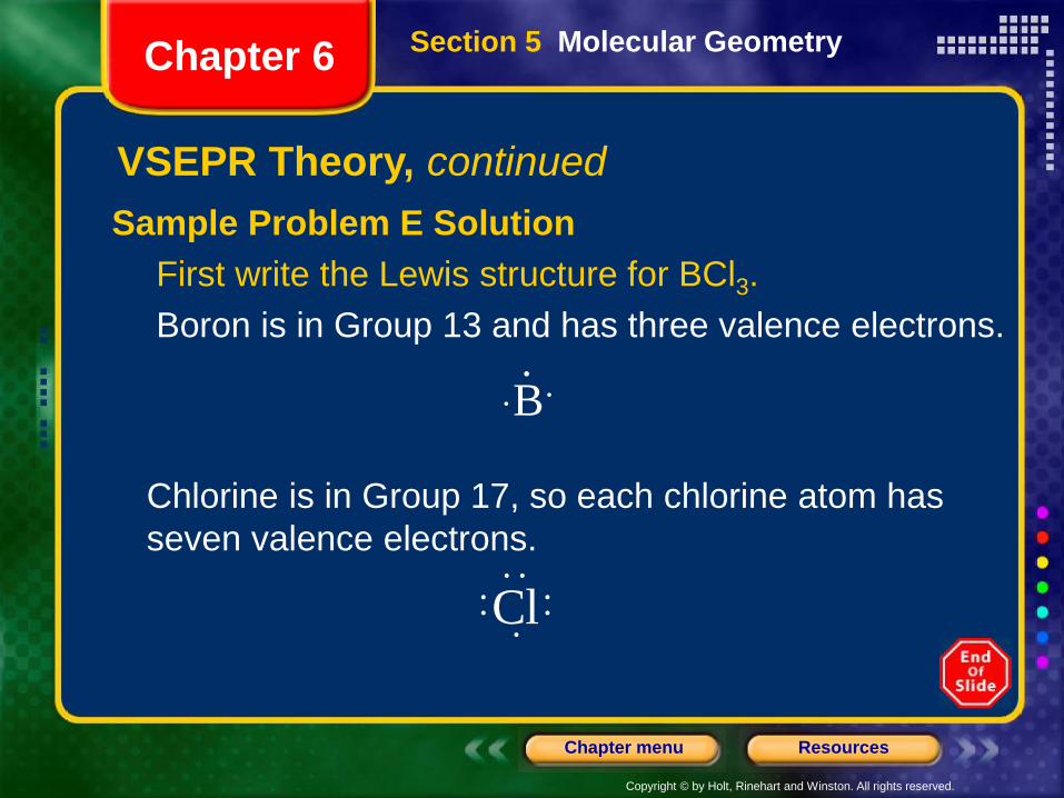
Sample Problem E Solution
First write the Lewis structure for BCl3.
Boron is in Group 13 and has three valence electrons.
B
Cl
Section 5 Molecular GeometryChapter 6
Chlorine is in Group 17, so each chlorine atom has
seven valence electrons.
Copyright © by Holt, Rinehart and Winston. All rights reserved.
ResourcesChapter menu
VSEPR Theory, continued
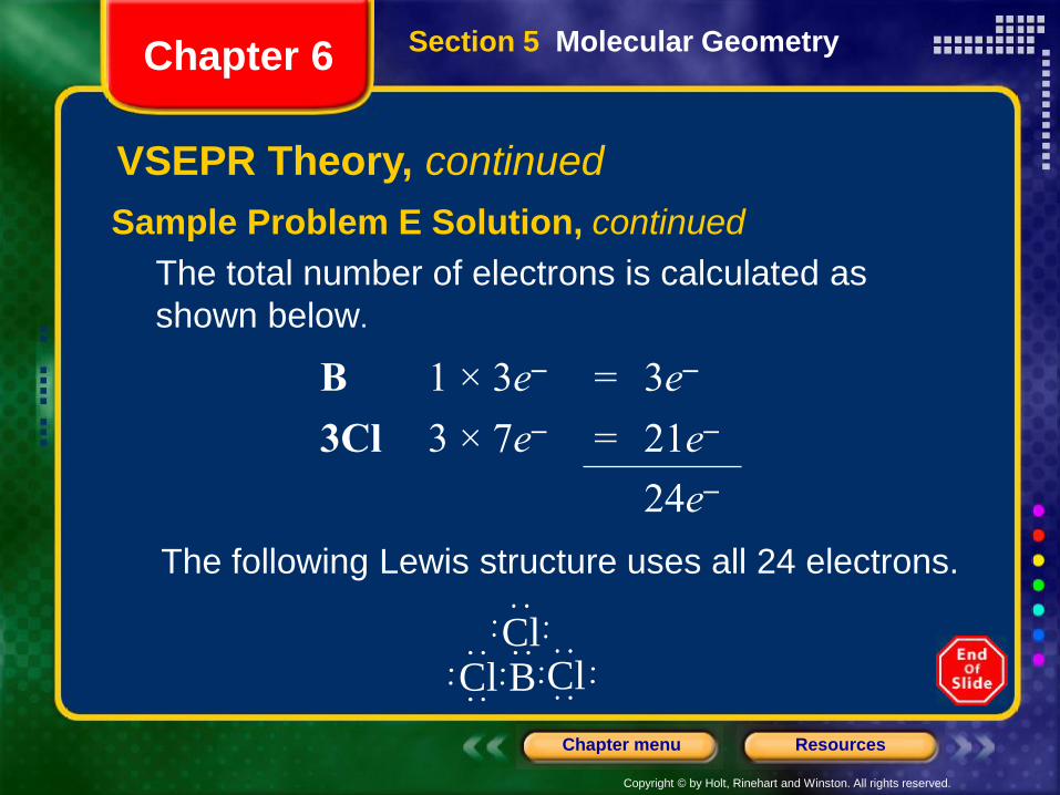
Sample Problem E Solution, continued
The total number of electrons is calculated as
shown below.
B 1 × 3e– = 3e–
3Cl 3 × 7e– = 21e–
24e–
The following Lewis structure uses all 24 electrons.
BCl
ClCl
Section 5 Molecular GeometryChapter 6
Copyright © by Holt, Rinehart and Winston. All rights reserved.
ResourcesChapter menu
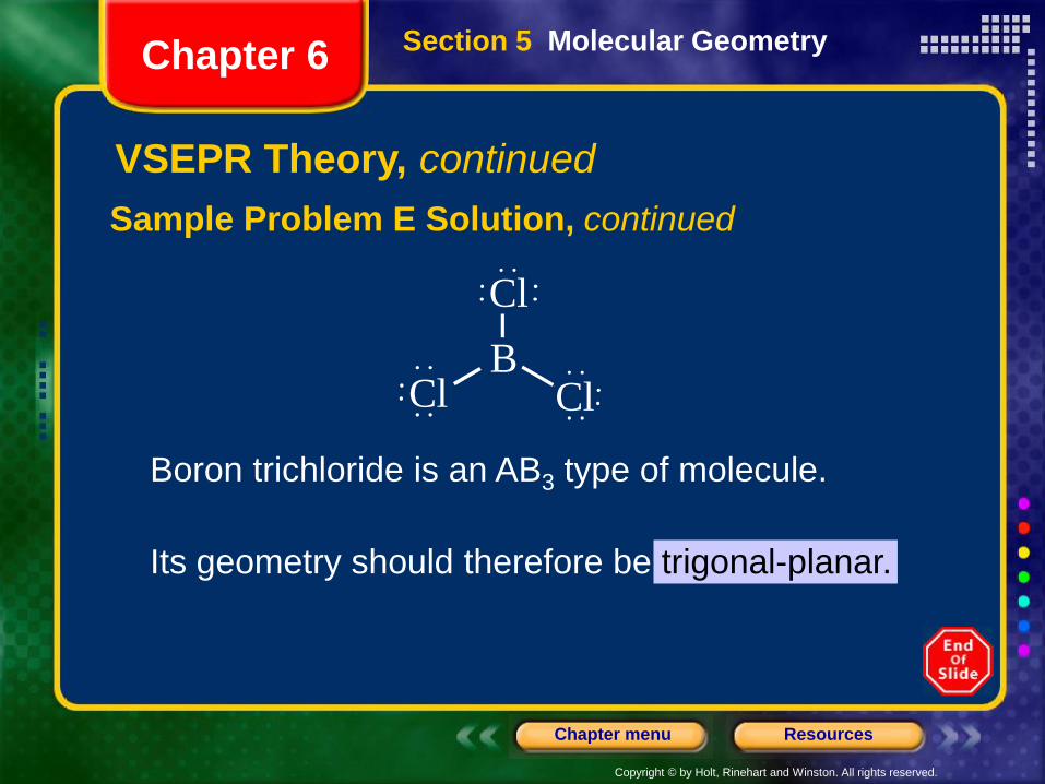
VSEPR Theory, continued
Sample Problem E Solution, continued
B
Cl
ClCl
Section 5 Molecular GeometryChapter 6
Boron trichloride is an AB3 type of molecule.
Its geometry should therefore be trigonal-planar.
Copyright © by Holt, Rinehart and Winston. All rights reserved.
ResourcesChapter menu
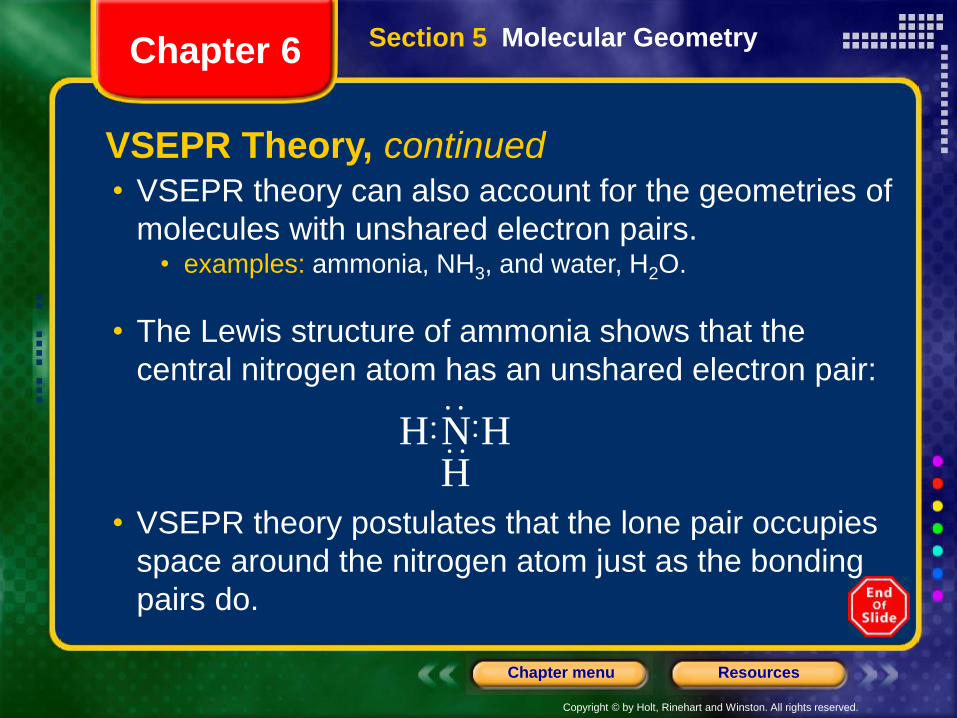
• VSEPR theory can also account for the geometries of
molecules with unshared electron pairs.• examples: ammonia, NH3, and water, H2O.
• The Lewis structure of ammonia shows that the
central nitrogen atom has an unshared electron pair:
• VSEPR theory postulates that the lone pair occupies
space around the nitrogen atom just as the bonding
pairs do.
N HHH
Section 5 Molecular GeometryChapter 6
VSEPR Theory, continued
Copyright © by Holt, Rinehart and Winston. All rights reserved.
ResourcesChapter menu
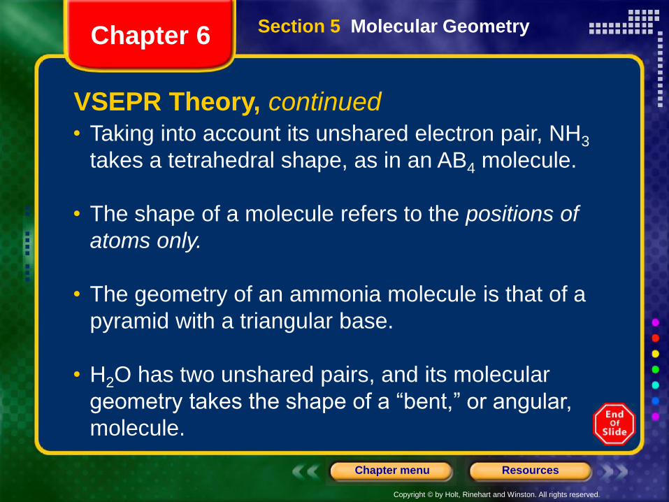
• Taking into account its unshared electron pair, NH3
takes a tetrahedral shape, as in an AB4 molecule.
• The shape of a molecule refers to the positions of
atoms only.
• The geometry of an ammonia molecule is that of a
pyramid with a triangular base.
• H2O has two unshared pairs, and its molecular
geometry takes the shape of a “bent,” or angular,
molecule.
Section 5 Molecular GeometryChapter 6
VSEPR Theory, continued
Copyright © by Holt, Rinehart and Winston. All rights reserved.
ResourcesChapter menu
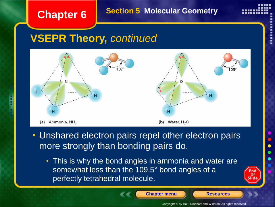
• Unshared electron pairs repel other electron pairs more strongly than bonding pairs do.
• This is why the bond angles in ammonia and water are somewhat less than the 109.5° bond angles of a perfectly tetrahedral molecule.
Section 5 Molecular GeometryChapter 6
VSEPR Theory, continued
Copyright © by Holt, Rinehart and Winston. All rights reserved.
ResourcesChapter menu
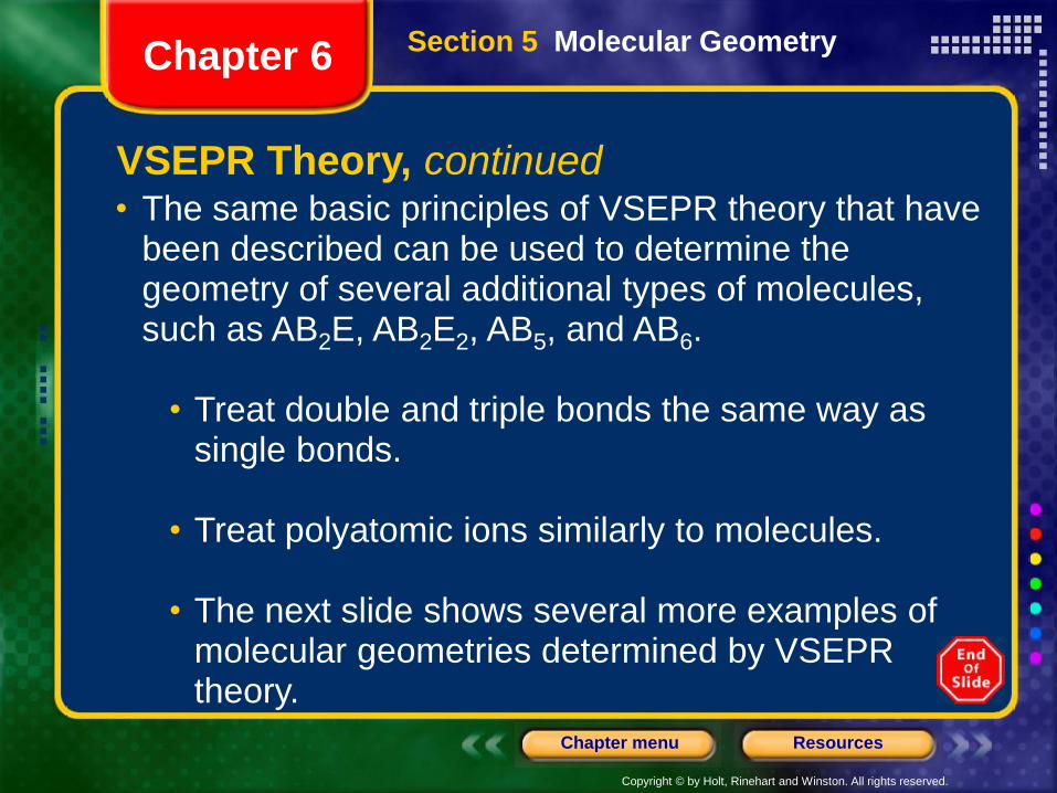
• The same basic principles of VSEPR theory that have been described can be used to determine the geometry of several additional types of molecules, such as AB2E, AB2E2, AB5, and AB6.
• Treat double and triple bonds the same way as single bonds.
• Treat polyatomic ions similarly to molecules.
• The next slide shows several more examples of molecular geometries determined by VSEPR theory.
Section 5 Molecular GeometryChapter 6
VSEPR Theory, continued
Copyright © by Holt, Rinehart and Winston. All rights reserved.
ResourcesChapter menu
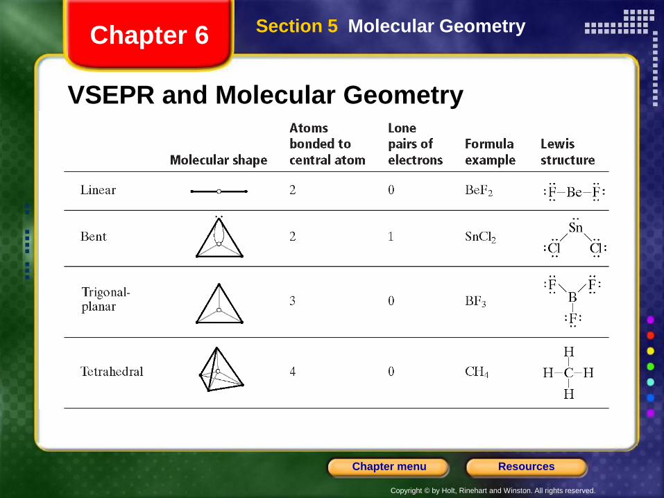
VSEPR and Molecular Geometry
Section 5 Molecular GeometryChapter 6
Copyright © by Holt, Rinehart and Winston. All rights reserved.
ResourcesChapter menu
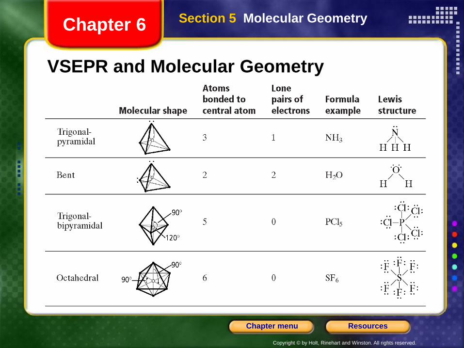
VSEPR and Molecular Geometry
Section 5 Molecular GeometryChapter 6
Copyright © by Holt, Rinehart and Winston. All rights reserved.
ResourcesChapter menu
Sample Problem F
a. Use VSEPR theory to predict the shape of a molecule
of carbon dioxide, CO2.
b. Use VSEPR theory to predict the shape of a chlorate
ion, .
Section 5 Molecular GeometryChapter 6
VSEPR Theory, continued
3ClO
Copyright © by Holt, Rinehart and Winston. All rights reserved.
ResourcesChapter menu
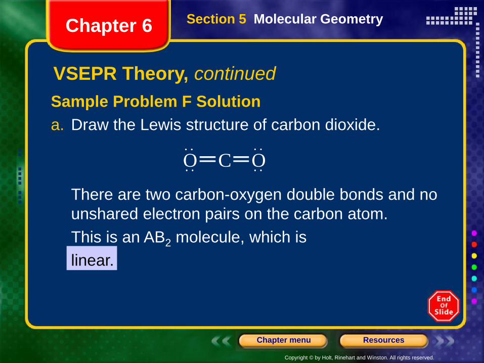
Sample Problem F Solution
a. Draw the Lewis structure of carbon dioxide.
There are two carbon-oxygen double bonds and no
unshared electron pairs on the carbon atom.
This is an AB2 molecule, which is
linear.
C OO
Section 5 Molecular GeometryChapter 6
VSEPR Theory, continued
Copyright © by Holt, Rinehart and Winston. All rights reserved.
ResourcesChapter menu
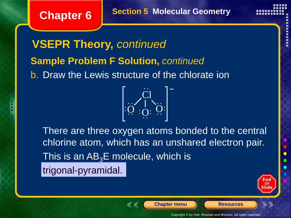
Sample Problem F Solution, continued
b. Draw the Lewis structure of the chlorate ion.
There are three oxygen atoms bonded to the central
chlorine atom, which has an unshared electron pair.
This is an AB3E molecule, which is
trigonal-pyramidal.
Cl
OOO
Section 5 Molecular GeometryChapter 6
VSEPR Theory, continued
Copyright © by Holt, Rinehart and Winston. All rights reserved.
ResourcesChapter menu
Hybridization
• VSEPR theory is useful for predicting and explaining the shapes of molecules.
• A step further must be taken to explain how the orbitals of an atom are rearranged when the atom forms covalent bonds.
• For this purpose, we use the model of hybridization,which is the mixing of two or more atomic orbitals of similar energies on the same atom to produce new hybrid atomic orbitals of equal energies.
Section 5 Molecular GeometryChapter 6
Copyright © by Holt, Rinehart and Winston. All rights reserved.
ResourcesChapter menu
Hybridization• Take the simple example of methane, CH4. The
carbon atom has four valence electrons, two in the 2sorbital and two in 2p orbitals.
• Experiments have determined that a methane molecule is tetrahedral. How does carbon form four equivalent, tetrahedrally arranged, covalent bonds?
• Recall that s and p orbitals have different shapes. To achieve four equivalent bonds, carbon’s 2s and three 2p orbitals hybridize to form four new, identical orbitals called sp3
orbitals.
• The superscript 3 on the p indicates that there are three porbitals included in the hybridization. The superscript 1 on the s is left out, like in a chemical formula.
Section 5 Molecular GeometryChapter 6
Copyright © by Holt, Rinehart and Winston. All rights reserved.
ResourcesChapter menu
Hybridization, continued
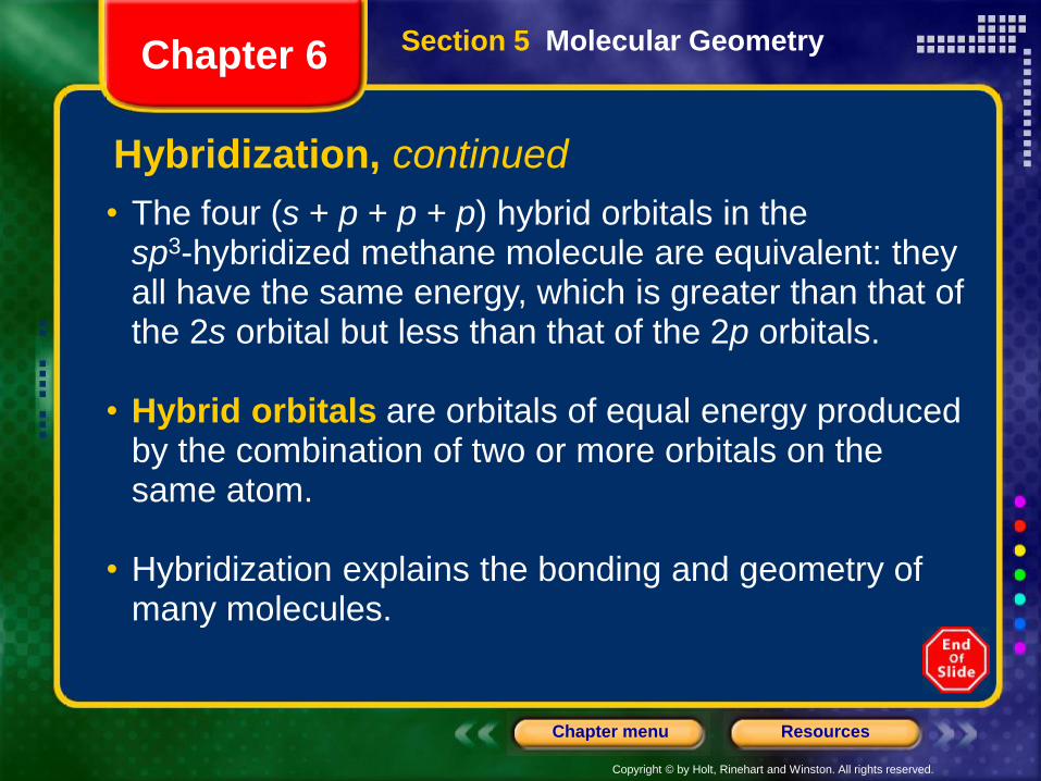
• The four (s + p + p + p) hybrid orbitals in the sp3-hybridized methane molecule are equivalent: they all have the same energy, which is greater than that of the 2s orbital but less than that of the 2p orbitals.
• Hybrid orbitals are orbitals of equal energy produced by the combination of two or more orbitals on the same atom.
• Hybridization explains the bonding and geometry of many molecules.
Section 5 Molecular GeometryChapter 6
Copyright © by Holt, Rinehart and Winston. All rights reserved.
ResourcesChapter menu
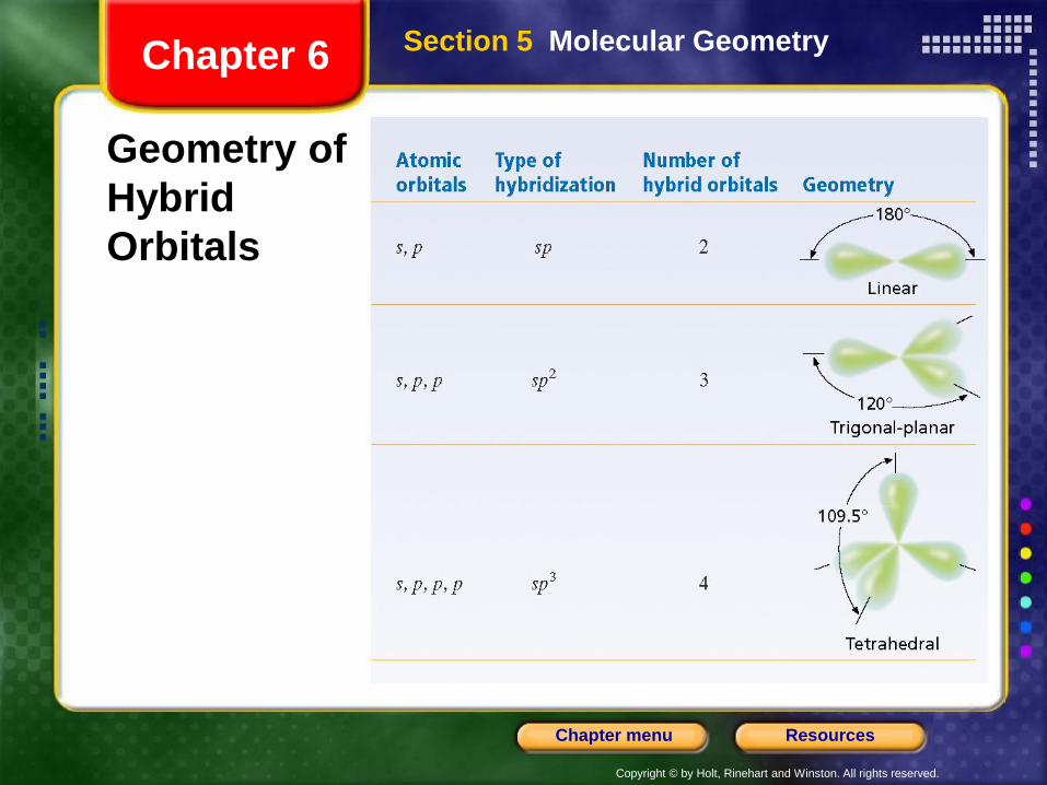
Geometry of
Hybrid
Orbitals
Section 5 Molecular GeometryChapter 6
Copyright © by Holt, Rinehart and Winston. All rights reserved.
ResourcesChapter menu
Intermolecular Forces
• The forces of attraction between molecules are known as intermolecular forces.
• The boiling point of a liquid is a good measure of the intermolecular forces between its molecules: the higher the boiling point, the stronger the forces between the molecules.
• Intermolecular forces vary in strength but are generally weaker than bonds between atoms within molecules, ions in ionic compounds, or metal atoms in solid metals.
• Boiling points for ionic compounds and metals tend to be much higher than those for molecular substances: forces between molecules are weaker than those between metal atoms or ions.
Section 5 Molecular GeometryChapter 6
Copyright © by Holt, Rinehart and Winston. All rights reserved.
ResourcesChapter menu
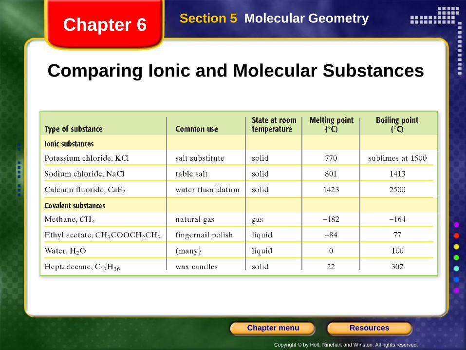
Comparing Ionic and Molecular Substances
Section 5 Molecular GeometryChapter 6
Copyright © by Holt, Rinehart and Winston. All rights reserved.
ResourcesChapter menu
Intermolecular Forces, continued
• The strongest intermolecular forces exist between polar molecules.
• Because of their uneven charge distribution, polar molecules have dipoles. A dipole is created by equal but opposite charges that are separated by a short distance.
• The direction of a dipole is from the dipole’s positive pole to its negative pole.
Section 5 Molecular GeometryChapter 6
Copyright © by Holt, Rinehart and Winston. All rights reserved.
ResourcesChapter menu
Intermolecular Forces, continued
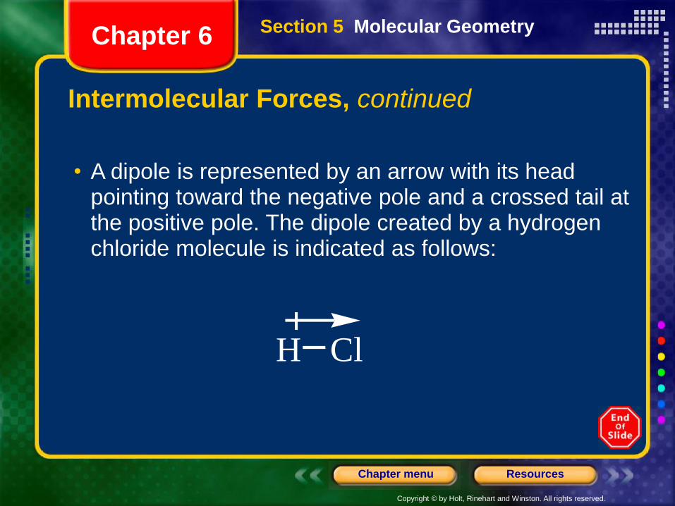
• A dipole is represented by an arrow with its head pointing toward the negative pole and a crossed tail at the positive pole. The dipole created by a hydrogen chloride molecule is indicated as follows:
H Cl
Section 5 Molecular GeometryChapter 6
Copyright © by Holt, Rinehart and Winston. All rights reserved.
ResourcesChapter menu
Intermolecular Forces, continued
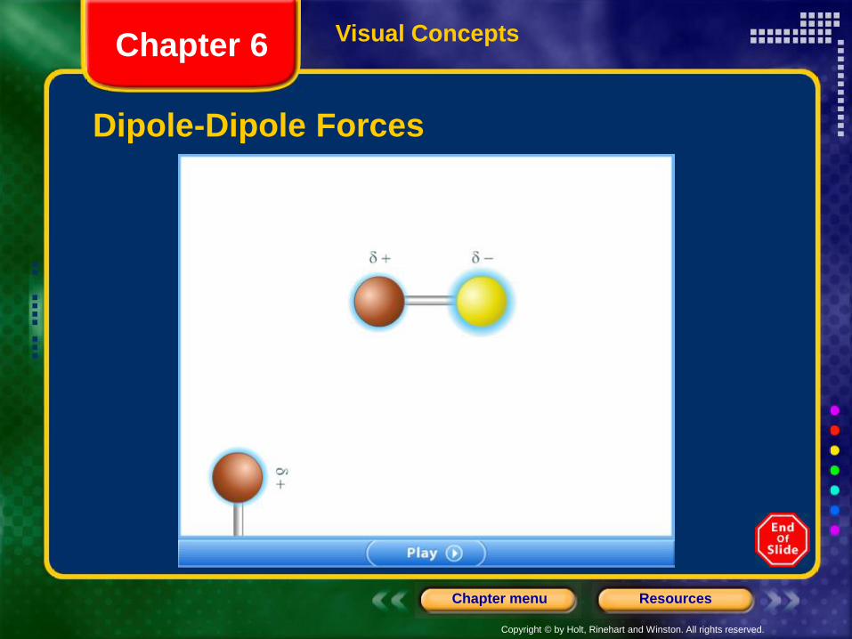
• The negative region in one polar molecule attracts the positive region in adjacent molecules. So the molecules all attract each other from opposite sides.
• Such forces of attraction between polar molecules are known as dipole-dipole forces.
• Dipole-dipole forces act at short range, only between nearby molecules.
• Dipole-dipole forces explain, for example the difference between the boiling points of iodine chloride, I–Cl (97°C), and bromine, Br–Br (59°C).
Section 5 Molecular GeometryChapter 6
Copyright © by Holt, Rinehart and Winston. All rights reserved.
ResourcesChapter menu
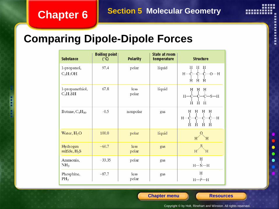
Comparing Dipole-Dipole Forces
Section 5 Molecular GeometryChapter 6
Copyright © by Holt, Rinehart and Winston. All rights reserved.
ResourcesChapter menu
Visual Concepts
Dipole-Dipole Forces
Chapter 6
Copyright © by Holt, Rinehart and Winston. All rights reserved.
ResourcesChapter menu
Intermolecular Forces, continued
• A polar molecule can induce a dipole in a nonpolar molecule by temporarily attracting its electrons.
• The result is a short-range intermolecular force that is somewhat weaker than the dipole-dipole force.
• Induced dipoles account for the fact that a nonpolar molecule, oxygen, O2, is able to dissolve in water, a polar molecule.
Section 5 Molecular GeometryChapter 6
Copyright © by Holt, Rinehart and Winston. All rights reserved.
ResourcesChapter menu
Intermolecular Forces, continued
• Some hydrogen-containing compounds have unusually high boiling points. This is explained by a particularly strong type of dipole-dipole force.
• In compounds containing H–F, H–O, or H–N bonds, the large electronegativity differences between hydrogen atoms and the atoms they are bonded to make their bonds highly polar.
• This gives the hydrogen atom a positive charge that is almost half as large as that of a bare proton.
Section 5 Molecular GeometryChapter 6
Copyright © by Holt, Rinehart and Winston. All rights reserved.
ResourcesChapter menu
Intermolecular Forces, continued
• The small size of the hydrogen atom allows the atom to come very close to an unshared pair of electrons in an adjacent molecule.
• The intermolecular force in which a hydrogen atom that is bonded to a highly electronegative atom is attracted to an unshared pair of electrons of an electronegative atom in a nearby molecule is known as hydrogen bonding.
Section 5 Molecular GeometryChapter 6
Copyright © by Holt, Rinehart and Winston. All rights reserved.
ResourcesChapter menu
Intermolecular Forces
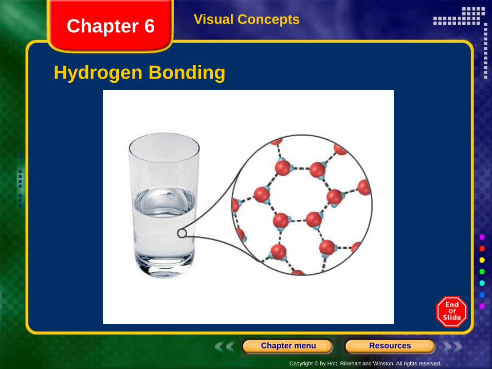
• Hydrogen bonds are usually represented by dotted lines connecting the hydrogen-bonded hydrogen to the unshared electron pair of the electronegative atom to which it is attracted.
• An excellent example of hydrogen bonding is that which occurs between water molecules. The strong hydrogen bonding between water molecules accounts for many of water’s characteristic properties.
Section 5 Molecular GeometryChapter 6
Copyright © by Holt, Rinehart and Winston. All rights reserved.
ResourcesChapter menu
Visual Concepts
Hydrogen Bonding
Chapter 6
Copyright © by Holt, Rinehart and Winston. All rights reserved.
ResourcesChapter menu
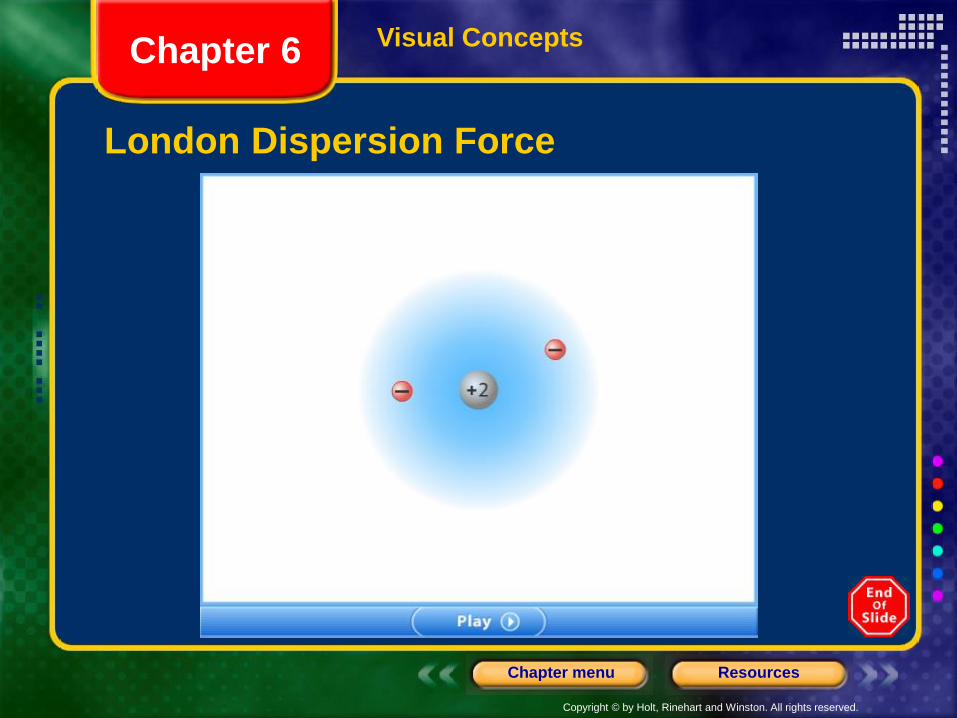
Intermolecular Forces, continuedLondon Dispersion Forces
• Even noble gas atoms and nonpolar molecules can experience weak intermolecular attraction.
• In any atom or molecule—polar or nonpolar—the electrons are in continuous motion.
• As a result, at any instant the electron distribution may be uneven. A momentary uneven charge can create a positive pole at one end of an atom of molecule and a negative pole at the other.
Section 5 Molecular GeometryChapter 6
Copyright © by Holt, Rinehart and Winston. All rights reserved.
ResourcesChapter menu
Intermolecular Forces, continuedLondon Dispersion Forces, continued
• This temporary dipole can then induce a dipole in an adjacent atom or molecule. The two are held together for an instant by the weak attraction between temporary dipoles.
• The intermolecular attractions resulting from the constant motion of electrons and the creation of instantaneous dipoles are called London dispersion forces.
• Fritz London first proposed their existence in 1930.
Section 5 Molecular GeometryChapter 6
Copyright © by Holt, Rinehart and Winston. All rights reserved.
ResourcesChapter menu
Visual Concepts
London Dispersion Force
Chapter 6
Copyright © by Holt, Rinehart and Winston. All rights reserved.
ResourcesChapter menu
End of Chapter 6 Show