Embed Size (px)
Citation preview
Chapter 5Vibration Energy Harvesting and ItsApplication for Nano- and Microrobotics
Junjun Ding, Vinod R. Challa, M. G. Prasadand Frank T. Fisher
Abstract In this chapter, the concept of vibration energy harvesting and its potentialutilization as a power source for micro/nanorobots is introduced and discussed. Whilebatteries are commonly used as power sources for electronic devices, the limitedlifetime and relatively large dimensional structure of batteries constrain its applica-tions in micro/nanodevices. On the other hand, while capacitors have an extremelycompact structure, the power stored is generally considered too low to power micro/nanorobots for a sufficiently long period of time. Hence, energy harvesting approaches,either alone or in conjunction with more traditional power sources, are being inves-tigated to provide sufficient power for micro/nanorobots over the design lifetime of thesystem. In general, several varieties of energy harvesting techniques and devices havebeen developed to transfer different energy sources that may be present in a particularenvironment into electrical power; for example, solar, thermal, mechanical vibration,and even wind energy can be used as the source for energy harvesting devices inappropriate applications. However, specifically considering micro/nanodevices forbiomedical applications greatly restricts the potential energy sources that can beharvested for system power. In this case, mechanical (vibration) energy may serve as auseful environmental source for energy harvesting. The purpose of this chapter is tofirst introduce the reader to the general field of energy harvesting, after which thediscussion will focus on mechanical vibration energy harvesting and other techniqueswith potentially greater application to biomedical nano/microrobotics. In particular,different vibration energy harvesting mechanisms, such as electromagnetic, electro-static, and piezoelectric techniques, will then be presented. The chapter concludes withrecent work being done in the field of nanotechnology to further extend these energyharvesting approaches to size scales compatible with nano/micro devices and systems.
J. Ding � V. R. Challa � M. G. Prasad � F. T. Fisher (&)Department of Mechanical Engineering, Stevens Institute of Technology,Hoboken, NJ 07030, USAe-mail: [email protected]
Y. Guo (ed.), Selected Topics in Micro/Nano-Robotics for Biomedical Applications,DOI: 10.1007/978-1-4419-8411-1_5, � Springer Science+Business Media New York 2013
59
5.1 Introduction
In the most general terms, energy harvesting (also referred to as energy scavengingor power harvesting in the literature) describes a process whereby energy in agiven environment is transferred into a more useful form of electrical energy.Energy is the amount of power consumed, expressed in watt-hours or kilowatt-hours, while power is often expressed in watts or kilowatts. Energy is equal to thepower multiplied by the time of consumption. Thus, in specific terms energyharvesting is somewhat of a misnomer, as technically the area should be referred toas power harvesting (although following common convention the term energyharvesting will be used here). The sources of energy that can be harvested arepractically limitless, and in the most general terms can include sources such assolar energy, thermal energy, wind energy, tidal and wave energy, and mechanicaland vibration energy. Further, the scales on which energy harvesting can bepursued can vary drastically, generating anywhere from utility-level power levelsin applications such as hydroelectric dams, wind (turbine) farms, and solar (orphotovoltaic) applications to energy harvesting at much smaller scales, wheremicro- (or even nano-) watt levels of electrical energy that are generated are usefulfor a small-scale device or system. It is the latter level of energy that is of par-ticular interest for micro/nanorobots and will be the focus of the present chapter.Despite the broad, general definition of energy harvesting given above, in manycases (including in this chapter), the term energy harvesting is used in the contextof much smaller levels of power which are likely to be on the orders of milliwatts(mW) for most micro/nanorobots applications.
While the power available from mechanical vibrations in an environment isgenerally small, the power requirement of micro/nanorobots is low and thereforethis approach has great potential in the powering of micro/nanorobotic devices andsystems. For example, a particular application of interest is the powering of futurebio-microsystems that consist of low-power transducers, low-power integratedcircuits (IC), and passive sensors, specifically designed to consume low amountsof power to extend their battery life. In order to place the power needed formicroscale robots in perspective, the power consumed by insects of similar sizecan be illustrative. Results compiled in the literature [1] show that the commonfruit fly (Drosophila virilis) has a mass of 0.001 g and requires 0.03 mW of power,while insects approximately 1 g in mass require approximately 1–50 mW ofpower, resulting in specific power (power per unit mass) values on the order oftens of W/kg. On the other hand, implantable intraocular pressure microsensorswith a power consumption of 4.2 nW have been powered by microbatteries [2],while an artificial mechanical white cell of microscopic size called a microbivoremay consume up to 200 pW of continuous power while completely digestingtrapped microbes [3]. Such implantable biosensors are generally restricted in termsof the space available for power sources, thus power scavenging approaches are anattractive means to extend the operational lifetime of these systems.
60 J. Ding et al.
Methods of storing and supplying power at small length scales is a challengingtopic for micro/nanorobots, and likely represents one of the largest obstacles torealizing functional micro/nanorobots in the future. Because of the energy densityand volume of batteries, they are generally not suitable (or promising) for micro/nanorobots. Recent advances seeking to leverage nanotechnology to further batterytechnology have met with mixed reviews, and while thin-film batteries may ulti-mately enable integration with MEMS devices, they are likely to struggle withproviding a sufficiently long-term power source for micro/nanorobots. Thus, theprojected limited lifetime of microbatteries has motivated the pursuit of energyharvesting approaches as a means to provide power to these systems.
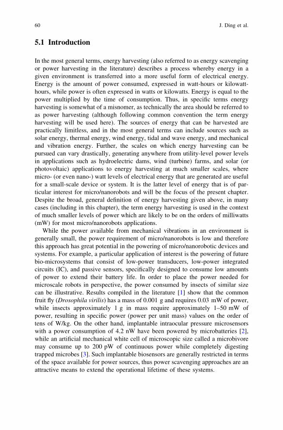
In general, an energy harvesting approach requires a transduction mechanismwhich transfers energy from the ambient environmental source into electricalenergy, and a conditioning (and/or storage) system which conditions the acquiredelectrical energy into a form which can be either immediately used by the largersystem or appropriately stored for later use (Fig. 5.1). Here, the transductionmechanism is responsible for generating electrical energy from the ambient sourceenergy, for example, mechanical vibrations or temperature gradients. Electricalcircuitry is often needed to modify the harvested electrical energy, for exampleconverting or rectifying an AC input into DC for storage in an appropriate elec-trical system, for example batteries or capacitors. Generally, the rate at which theenergy is harvested is quite low, which requires a gradual filling of the electricalstorage element until a threshold value has been achieved that indicates that suf-ficient energy is available for the desired operation. A common analogy to illus-trate this principle is slowly filling a bucket with water, where the energy harvestedand energy available in the energy storage system are represented by the waterflowing into the bucket and the overall amount of water in the bucket, respectively.
As noted above this filling process is typically quite slow, and is generallyaccomplished while the system is in a low-power consumption mode (or sleepmode). Once a sufficient level of power is available in the system, the overallsystem ‘wakes up’ and expends energy in doing its programed task, after which thesystem re-enters its sleep mode and continues harvesting energy until sufficientenergy is available for the next cycle to commence as governed by a micropro-cessor or alternative control mechanism. For example, as shown in Fig. 5.1, theharvester is used to ultimately power a sensor for data collection and a transmitterfor data transmission. Clearly, a careful balance of the energy harvested to theenergy required by the overall system will largely control the ratio of the length of
Fig. 5.1 Schematic of awireless sensor node using asmall-scale energy harvesterto power data collection andwireless data transmission
5 Vibration Energy Harvesting and Its Application for Nano- and Microrobotics 61
the sleep-to-wake cycles. Recent advances in low-power electronics related to thepower consumption for components such as the sensors, transmitters, and micro-processors are promising in this regard.
Although a new field, as advances in energy harvesting methodologies on theone hand and low-power electronics on the other converge it will greatly expandthe prospects of energy harvesting approaches for small-scale robotics applica-tions. Depending on the available energy and the power requirements of the micro/nanorobot, energy harvesting may be suitable for either a stand-alone powersource, where the entire system is powered via the harvested energy, or alterna-tively used in trickle-charge mode, where energy harvesting is used to supplement(and hence extend the lifetime of) more traditional power sources such as batteries.A key factor from an overall system design standpoint will be that the extra costand complexity associated with energy harvesting is outweighed by the enhancedsystem performance that energy harvesting adds to the system. In this sense, thelow size and power requirements and inaccessibility of micro/nanorobots whenused for biomedical applications seems to provide a suitable niche for continuedresearch in this area.
5.2 Alternative Power Sources for Micro/Nanorobotics
5.2.1 Batteries
Because of their relatively high power density, portability, and interchangeability,batteries are the most commonly used power source in electronics ranging fromsensors and cell phones to computer laptops and other consumer products. Bat-teries not only can be used as a power source, but also as a power storage device asin the case of rechargeable batteries. Batteries are in general simple to implement,can provide a continuous power supply, and can be readily replaced as necessaryin many applications where they are accessible.
Today, lithium-ion batteries are rapidly being developed to replace nickel metalhydride (NiMH) and nickel cadmium batteries for portable and hand held devices.Lithium-ion batteries can achieve specific energy levels of 120–130 Wh/kg, whichis more than 50 % higher than that of typical portable NiMH batteries [4]. Lith-ium-ion batteries have a relatively long cycle life, broad operating temperaturerange, low self-discharge rate, rapid charge capability, relatively high energydensity, high voltage output, and a lack of memory effect compared with othertypes of electrochemical batteries [5]. Disadvantages of lithium-ion batteriesinclude capacity/power degradation at high temperatures and critical safety issues.In particular, lithium-ion batteries are sensitive to overcharging, which can lead tooverheating and internal short-circuiting which adversely affects the battery per-formance. The heat released from the lithium-ion batteries is significantly largeand can be problematic in some applications [6].
62 J. Ding et al.
The primary disadvantages of current batteries are the power-to-size and power-to-weight ratios, which have not kept pace with the rate of miniaturization of elec-tronics and other components that might make up a nano/microrobot or system. Thisleads to the current situation where the relative weight of the battery, as a percentageof overall system weight, increases as the electronic device is reduced in size. Forexample, for a current generation laptop computer, the battery is 13 % of the totalmass, while in a Motorola cell phone the battery comprises up to 36 % of the totalmass [5]. Recently, microbatteries using thin- and thick-film technology have beendeveloped to decrease the volumes of batteries and to facilitate integration withComplementary Metal Oxide Semiconductor (CMOS) IC and devices such asmicroprocessors [7]. Since the amount of active material in the cells is reduced, thethin-film cell microbatteries have low current output and capacity, and thus thelifetime of microbatteries is generally limited although researchers are working toaddress this limitation [8, 9]. In many respects, battery technology is a significantbottleneck to the realization of further reductions in the size and weight of portableelectronics, as battery technology has not been able to keep up with the pace ofminiaturization of other electronics components. This limitation is clearly of criticalconcern for future micro- and nanorobotics applications.
5.2.2 Fuel Cells
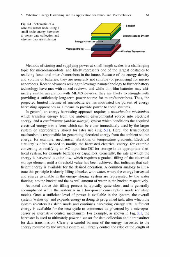
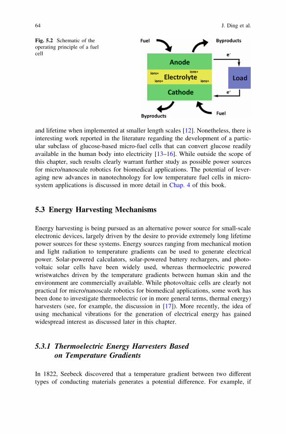
Like batteries, fuel cells generate power through an electrochemical process. Ingeneral, a fuel cell consists of an anode and cathode separated by an electrolyte asshown in Fig. 5.2. A chemical reaction takes place at the interfaces of these threeelements such that as the fuel is consumed electrical current (and hence electricalenergy) is generated and some byproducts produced. In a common hydrogen fuelcell, H2 and O2 are supplied to the anode and cathode, respectively, with thebyproduct H2O being emitted from the cathode side. For a direct methanol fuelcell, methanol and H2O and O2 are supplied to the anode and cathode, respec-tively, with CO2 and H2O byproducts generated at the anode and cathode,respectively. For example, the direct methanol fuel cell reaction equations areshown as following [10],
Anode CH3OH +H2O! 6Hþ þ 6e� þ CO2
Cathode 32 O2 þ 6Hþ þ 6e� ! 3H2O
Overall reaction CH3OH þ 32 O2 ! 2H2Oþ CO2
Large-scale fuel cells can achieve 40–70 % conversion efficiency [11]; mean-while, fuel cells operating on pure hydrogen have no emissions but water. Hence,fuel cells can provide competitive energy densities with low emissions at largerlength scales. However, due to the consumption of anode and electrolyte, thelifetime of fuel cells is limited to the availability to store the fuel. As with batteries,micro/nanoscale fuel cells generally have limitations with respect to power density
5 Vibration Energy Harvesting and Its Application for Nano- and Microrobotics 63
and lifetime when implemented at smaller length scales [12]. Nonetheless, there isinteresting work reported in the literature regarding the development of a partic-ular subclass of glucose-based micro-fuel cells that can convert glucose readilyavailable in the human body into electricity [13–16]. While outside the scope ofthis chapter, such results clearly warrant further study as possible power sourcesfor micro/nanoscale robotics for biomedical applications. The potential of lever-aging new advances in nanotechnology for low temperature fuel cells in micro-system applications is discussed in more detail in Chap. 4 of this book.
5.3 Energy Harvesting Mechanisms
Energy harvesting is being pursued as an alternative power source for small-scaleelectronic devices, largely driven by the desire to provide extremely long lifetimepower sources for these systems. Energy sources ranging from mechanical motionand light radiation to temperature gradients can be used to generate electricalpower. Solar-powered calculators, solar-powered battery rechargers, and photo-voltaic solar cells have been widely used, whereas thermoelectric poweredwristwatches driven by the temperature gradients between human skin and theenvironment are commercially available. While photovoltaic cells are clearly notpractical for micro/nanoscale robotics for biomedical applications, some work hasbeen done to investigate thermoelectric (or in more general terms, thermal energy)harvesters (see, for example, the discussion in [17]). More recently, the idea ofusing mechanical vibrations for the generation of electrical energy has gainedwidespread interest as discussed later in this chapter.
5.3.1 Thermoelectric Energy Harvesters Basedon Temperature Gradients
In 1822, Seebeck discovered that a temperature gradient between two differenttypes of conducting materials generates a potential difference. For example, if
Fig. 5.2 Schematic of theoperating principle of a fuelcell
64 J. Ding et al.
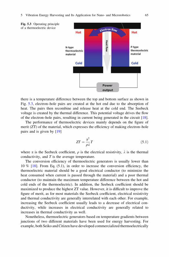
there is a temperature difference between the top and bottom surface as shown inFig. 5.3, electron–hole pairs are created at the hot end due to the absorption ofheat. The pairs then recombine and release heat at the cold end. The Seebeckvoltage is created by the thermal difference. This potential voltage drives the flowof the electron–hole pairs, resulting in current being generated in the circuit [18].
The performance of thermoelectric devices mainly depends on the figure ofmerit (ZT) of the material, which expresses the efficiency of making electron–holepairs and is given by [19]
ZT ¼ a2
qkT ð5:1Þ
where a is the Seebeck coefficient, q is the electrical resistivity, k is the thermalconductivity, and T is the average temperature.
The conversion efficiency of thermoelectric generators is usually lower than10 % [18]. From Eq. (5.1), in order to increase the conversion efficiency, thethermoelectric material should be a good electrical conductor (to minimize theheat consumed when current is passed through the material) and a poor thermalconductor (to maintain the maximum temperature difference between the hot andcold ends of the thermoelectric). In addition, the Seebeck coefficient should bemaximized to produce the highest ZT value. However, it is difficult to improve thefigure of merit, as for most materials the Seebeck coefficient, electrical resistivityand thermal conductivity are generally interrelated with each other. For example,increasing the Seebeck coefficient usually leads to a decrease of electrical con-ductivity, while increases in electrical conductivity are generally related toincreases in thermal conductivity as well.
Nonetheless, thermoelectric generators based on temperature gradients betweenjunctions of two different materials have been used for energy harvesting. Forexample, both Seiko and Citizen have developed commercialized thermoelectrically
Fig. 5.3 Operating principleof a thermoelectric device
5 Vibration Energy Harvesting and Its Application for Nano- and Microrobotics 65
powered wristwatches [20]. However, for thermal energy harvesters, one challengethat greatly limits its applicability for micro/nanoscale robotics for biomedicalapplications is the general need of a thermal gradient. Slight temperature differences,which may be lower than 1 �K, are generally found in the human body and areunlikely to be sufficient to produce sufficient power for micro/nanorobots operatinginside the body. Thus, the most promising applications of thermal energy harvesterswhere the human body is the power source are typically limited to their use on or veryclose to the skin surface.
More promising are approaches that harvest energy from kinetic sources, whichcould range anywhere from the relative movement of knees and shoulders to bloodflow in the body to the beating of the human heart. For applications where the goalis the powering of micro/nanoscale robotics within the human body, kinetic energysources that are interior to the human body are of primary interest and will be thefocus of the discussion for the remainder of this chapter.
5.3.2 Mechanical Vibration Energy Harvesters
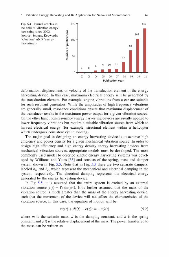
Vibrations are sources of (kinetic) mechanical energy that exist in almost everyenvironment. There are two types of vibrations, free vibrations and forcedvibrations. Free vibrations are initiated by an external source but continue tovibrate without the presence of an external force at the natural frequency of thesystem. These vibrations decrease in magnitude over time due to damping effectsthat are present in any system. On the other hand, forced vibrations are constantlysubjected to an external force or motion. In free vibrations, energy is exchangedwith the environment through damping and the process of harvesting electricalenergy from these mechanical vibrations necessarily results in the additionaldamping impacting the behavior of the system. Both free and forced vibrations areof interest from the perspective of energy harvesting, as the particular type ofvibration to be considered for a given application is predominantly based on thetypes of vibration available. One can readily observe the explosion of interest inthe field of vibration energy harvesting in the first decade of the twenty-firstcentury by examining the number of journal articles indexed per year in a popularscience citation database as shown in Fig. 5.4. Further, more recently MEMS-scalevibration energy harvesting has been pursued by a number of researchers due tothe potential benefits of harvesting at this length scale and the prevalence ofvibrations in almost all environments. A summary of recent experimental poweroutputs under different conditions for vibration energy harvesters is shown inTable 5.1.
Vibration energy harvesters generate electrical energy from mechanicalvibrations in the environment. In general, electrical energy harvested frommechanical vibration energy can be classified as resonance or non-resonance based[32]. In the resonance-based approach, the device is designed to be in resonancewith the frequency of the environmental vibration source to obtain maximum
66 J. Ding et al.
deformation, displacement, or velocity of the transduction element in the energyharvesting device. In this case, maximum electrical energy will be generated bythe transduction element. For example, engine vibrations from a car are suitablefor such resonant generators. While the amplitudes of high frequency vibrationsare generally small, resonance conditions ensure that maximum displacement ofthe transducer results in the maximum power output for a given vibration source.On the other hand, non-resonance energy harvesting devices are usually applied tolower frequency vibrations but require a suitable vibration source from which toharvest electrical energy (for example, structural element within a helicopterwhich undergoes consistent cyclic loading).
The major goal in designing an energy harvesting device is to achieve highefficiency and power density for a given mechanical vibration source. In order todesign high efficiency and high energy density energy harvesting devices frommechanical vibration sources, appropriate models must be developed. The mostcommonly used model to describe kinetic energy harvesting systems was devel-oped by Williams and Yates [33] and consists of the spring, mass and dampersystem shown in Fig. 5.5. Note that in Fig. 5.5 there are two separate dampers,labeled bm and be, which represent the mechanical and electrical damping in thesystem, respectively. The electrical damping represents the electrical energygenerated by the energy harvesting device.
In Fig. 5.5, it is assumed that the entire system is excited by an externalvibration source yðtÞ ¼ Y0 sinðxtÞ. It is further assumed that the mass of thevibration source is much greater than the mass of the energy harvesting device,such that the movement of the device will not affect the characteristics of thevibration source. In this case, the equation of motion will be
m€zðtÞ þ d _zðtÞ þ kðzÞt ¼ �m€yðtÞ ð5:2Þ
where m is the seismic mass, d is the damping constant, and k is the springconstant, and z(t) is the relative displacement of the mass. The power transferred tothe mass can be written as
Fig. 5.4 Journal articles inthe field of vibration energyharvesting since 2002.(source: Scopus, Keywords:‘vibration’ AND ‘energyharvesting’)
5 Vibration Energy Harvesting and Its Application for Nano- and Microrobotics 67
PðtÞ ¼ �m€yðtÞ½ _yðtÞ þ _zðtÞ� ð5:3Þ
Further, it can be shown that the electrical power produced by the electricaldamper can be written as [33]
Fig. 5.5 Schematic of ageneric energy harvestingdevice
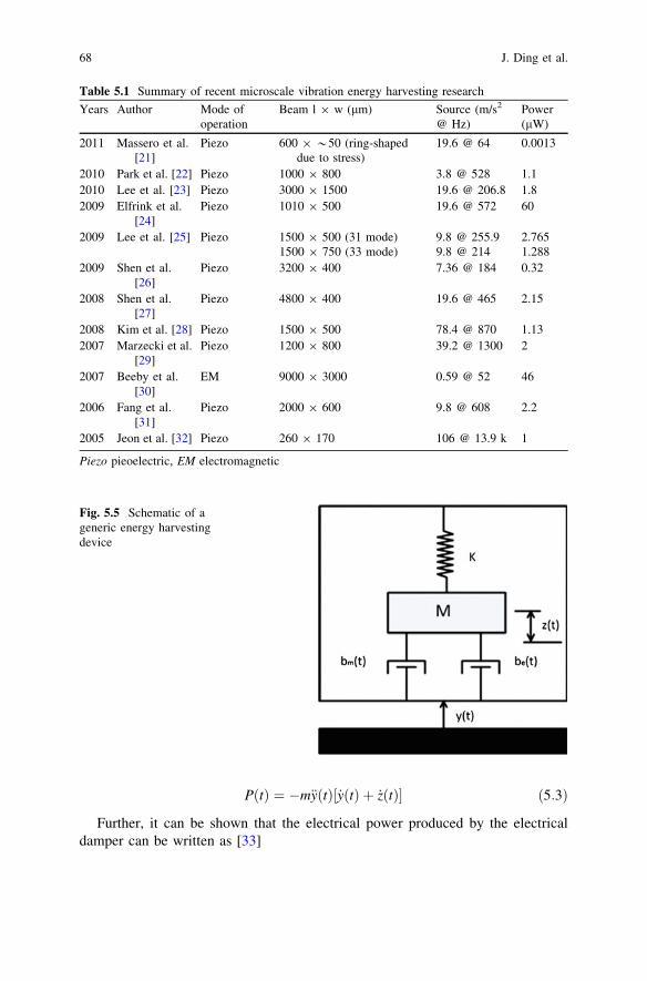
Table 5.1 Summary of recent microscale vibration energy harvesting research
Years Author Mode ofoperation
Beam l 9 w (lm) Source (m/s2
@ Hz)Power(lW)
2011 Massero et al.[21]
Piezo 600 9 *50 (ring-shapeddue to stress)
19.6 @ 64 0.0013
2010 Park et al. [22] Piezo 1000 9 800 3.8 @ 528 1.12010 Lee et al. [23] Piezo 3000 9 1500 19.6 @ 206.8 1.82009 Elfrink et al.
[24]Piezo 1010 9 500 19.6 @ 572 60
2009 Lee et al. [25] Piezo 1500 9 500 (31 mode)1500 9 750 (33 mode)
9.8 @ 255.99.8 @ 214
2.7651.288
2009 Shen et al.[26]
Piezo 3200 9 400 7.36 @ 184 0.32
2008 Shen et al.[27]
Piezo 4800 9 400 19.6 @ 465 2.15
2008 Kim et al. [28] Piezo 1500 9 500 78.4 @ 870 1.132007 Marzecki et al.
[29]Piezo 1200 9 800 39.2 @ 1300 2
2007 Beeby et al.[30]
EM 9000 9 3000 0.59 @ 52 46
2006 Fang et al.[31]
Piezo 2000 9 600 9.8 @ 608 2.2
2005 Jeon et al. [32] Piezo 260 9 170 106 @ 13.9 k 1
Piezo pieoelectric, EM electromagnetic
68 J. Ding et al.
PeðtÞ ¼mftY
2o
xxn
� �3x3
1� xxn
� �2� �2
þ 2ftxxn
h i2ð5:4Þ
where Y0 is the amplitude of vibration, x is the angular frequency of the vibrationsource, xn is the natural frequency of the device, and ft is the total damping ratioin the system (i.e. the sum of the individual damping components) such that
ft ¼ fe þ fm ð5:5Þ
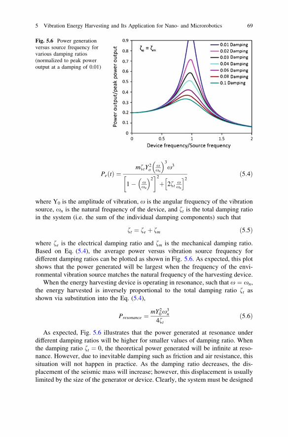
where fe is the electrical damping ratio and fm is the mechanical damping ratio.Based on Eq. (5.4), the average power versus vibration source frequency fordifferent damping ratios can be plotted as shown in Fig. 5.6. As expected, this plotshows that the power generated will be largest when the frequency of the envi-ronmental vibration source matches the natural frequency of the harvesting device.
When the energy harvesting device is operating in resonance, such that x ¼ xn,the energy harvested is inversely proportional to the total damping ratio ft asshown via substitution into the Eq. (5.4),
Presonance ¼mY2
0 x3n
4ftð5:6Þ
As expected, Fig. 5.6 illustrates that the power generated at resonance underdifferent damping ratios will be higher for smaller values of damping ratio. Whenthe damping ratio ft ¼ 0, the theoretical power generated will be infinite at reso-nance. However, due to inevitable damping such as friction and air resistance, thissituation will not happen in practice. As the damping ratio decreases, the dis-placement of the seismic mass will increase; however, this displacement is usuallylimited by the size of the generator or device. Clearly, the system must be designed
Fig. 5.6 Power generationversus source frequency forvarious damping ratios(normalized to peak poweroutput at a damping of 0.01)
5 Vibration Energy Harvesting and Its Application for Nano- and Microrobotics 69
to prevent the displacement of the mass from exceeding the maximum allowabledisplacement to protect the device from damage. Equation (5.6) suggests that themaximum power output will be obtained with the heaviest allowed seismic massthat does not result in failure of the vibrating system (such as material yielding,fatigue failure, etc.). Lastly, Eq. (5.6) shows that, for a constant excitation ampli-tude, power generation is proportional to the cubic of natural frequency, whichindicates higher frequency vibration sources produce higher power.
The discussion above has been for the case of a generic energy harvester and isindependent of the type of transduction mechanism employed in the device.Typically, vibration energy harvesting utilizes electromagnetic, electrostatic, orpiezoelectric transduction approaches as discussed below.
5.3.2.1 Electromagnetic Transduction Mechanism
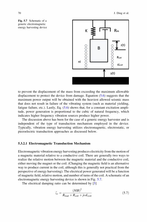
Electromagnetic vibration energy harvesting produces electricity from the motion ofa magnetic material relative to a conductive coil. There are generally two ways torealize the relative motion between the magnetic material and the conductive coil,either moving the magnet or the coil. (Changing the magnetic field is an alternativeway to produce current in the coil, although this is generally not practical from theperspective of energy harvesting). The electrical power generated will be a functionof magnetic field, relative motion, and number of turns of the coil. A schematic of anelectromagnetic energy harvesting device is shown in Fig. 5.7.
The electrical damping ratio can be determined by [5]
fe ¼ðNlBÞ2
Rload þ Rcoil þ jxLcoil
ð5:7Þ
Fig. 5.7 Schematic of ageneric electromagneticenergy harvesting device
70 J. Ding et al.
where N is the number of turns in the coil, B is the magnetic flux density, l is thecoil length per turn, Rcoil is the resistance of coil, Rload is the resistance of the load,and Lcoil is the coil inductance. By adjusting the load resistance such that theelectrical damping ratio fe is equal to the mechanical damping ratio fm, maximumpower can be obtained [5]. The maximum average power provided to the loadresistance under resonance conditions can be written as [5]
Pem�max ¼mA2
16fmxn1� Rcoil
Rload
� �ð5:8Þ
where A is the excitation acceleration and fm is the mechanical damping ratio.Since a low voltage is generally obtained from the electromagnetic technique, a
voltage up-converter is generally required for powering actual devices; the cor-responding electrical losses must be accounted for in the calculation of total powerharvested. Early work in this area includes the development of an electromagneticdevice that employs two magnets and four magnets coupled to a coil attached to acantilever beam [34]. An electromagnetic based generator for generating powerfrom ambient vibrations has also been presented [35]. Microscale electromagneticenergy harvesting devices have also been pursued [36]. The reader is directed tocomprehensive reviews available in the literature for more discussion of theelectromagnetic approach to vibration energy harvesting [5, 37].
5.3.2.2 Electrostatic Transduction Mechanism
Electrostatic vibration energy harvesters produce electrical energy by employing twoconductive plates moving relative to one another that are electrically isolated by air,vacuum, or dielectric insulator to form a capacitor. The change in capacitance can beachieved by a mechanical forcing function to generate electrical energy, either throughaltering the distance between the plates, the common area between the plates, or thedielectric material between the plates. The electrostatic energy harvesting techniqueoffers a major advantage of having the potential for implementation via silicon mi-cromachining processing allowing ease of integration with electronics.
There are two ways to convert energy from an electrostatic energy harvestingapproach, referred to as either charge (of the capacitor) constrained or voltageconstrained [38]. The voltage constrained mechanism generally provides a higherenergy output than the charge constrained approach; however, it requires anadditional voltage source which significantly complicates the device fabrication[39] (while any electrical losses due to the additional voltage source would need tobe factored into efficiency calculations for the harvester). Thus, for simplificationonly the power generated from the device for a charge constrained model isdiscussed here, which for a source frequency xs can be written as [40]
Pes ¼12
V2inxs Cmax � Cminð Þ Cmax þ Cpar
Cmin þ Cpar
� �ð5:9Þ
5 Vibration Energy Harvesting and Its Application for Nano- and Microrobotics 71
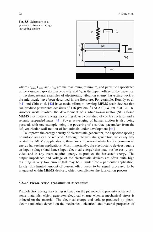
where Cmax, Cmin and Cpar are the maximum, minimum, and parasitic capacitanceof the variable capacitor, respectively, and Vin is the input voltage of the capacitor.
To date, several examples of electrostatic vibration energy harvesting work atthe microscale have been described in the literature. For example, Roundy et al.[41] and Chiu et al. [42] have made efforts to develop MEMS-scale devices thatcan produce power area densities of 116 lW cm-3 and 200 lW cm-2 at 120 Hz.Another work involves the development of a silicon-on-insulator (SOI) basedMEMS electrostatic energy harvesting device consisting of comb structures and aseismic suspended mass [43]. Power scavenging of human motion is also beingpursued, with one example being the powering of a cardiac pacemaker from theleft ventricular wall motion of lab animals under development [44].
To improve the energy density of electrostatic generators, the capacitor spacingor surface area can be reduced. Although electrostatic generators are easily fab-ricated for MEMS applications, there are still several obstacles for commercialenergy harvesting applications. Most importantly, the electrostatic devices requirean input voltage (and hence input electrical energy) that may not be easily pro-vided and in any event requires energy to produce the harvested energy. Theoutput impedance and voltage of the electrostatic devices are often quite highresulting in very low current that may be ill suited for a particular application.Lastly, this limited amount of current often needs to be signal processed to beintegrated within MEMS devices, which complicates the fabrication process.
5.3.2.3 Piezoelectric Transduction Mechanism
Piezoelectric energy harvesting is based on the piezoelectric property observed insome materials, which generates electrical charge when a mechanical stress isinduced on the material. The electrical charge and voltage produced by piezo-electric materials depend on the mechanical, electrical and material properties of
Fig. 5.8 Schematic of ageneric electrostatic energyharvesting device
72 J. Ding et al.
the piezoelectric materials and the stress applied on the material. Piezoelectric-based vibration energy harvesting is increasing in popularity due to the simplicityin capturing and storing the electrical energy generated; for example, a highvoltage output enables relatively simple circuitry for capturing the power output,although significant gains can be realized by optimizing the circuitry [45]. Becauseelectrical energy is produced simply due to the piezoelectric property of materials,such materials are typically employed as the vibrating structure. The constitutiveequations of piezoelectric energy harvesting can be written as
SD
� ¼ s
dde
� TE
� ð5:10Þ
where S is the strain in the piezoelectric material, D is the electrical displacement,s is compliance, d is piezoelectric strain coefficient, e is the dielectric, T is thestress, and E is the electric field.
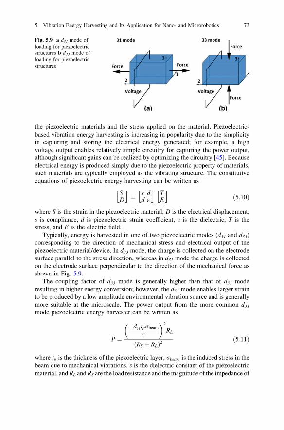
Typically, energy is harvested in one of two piezoelectric modes (d31 and d33)corresponding to the direction of mechanical stress and electrical output of thepiezoelectric material/device. In d33 mode, the charge is collected on the electrodesurface parallel to the stress direction, whereas in d31 mode the charge is collectedon the electrode surface perpendicular to the direction of the mechanical force asshown in Fig. 5.9.
The coupling factor of d33 mode is generally higher than that of d31 moderesulting in higher energy conversion; however, the d31 mode enables larger strainto be produced by a low amplitude environmental vibration source and is generallymore suitable at the microscale. The power output from the more common d31
mode piezoelectric energy harvester can be written as
P ¼
�d31 tprbeam
e
� �2
RL
ðRS þ RLÞ2ð5:11Þ
where tp is the thickness of the piezoelectric layer, rbeam is the induced stress in thebeam due to mechanical vibrations, e is the dielectric constant of the piezoelectricmaterial, and RL and RS are the load resistance and the magnitude of the impedance of
Fig. 5.9 a d31 mode ofloading for piezoelectricstructures b d33 mode ofloading for piezoelectricstructures
5 Vibration Energy Harvesting and Its Application for Nano- and Microrobotics 73
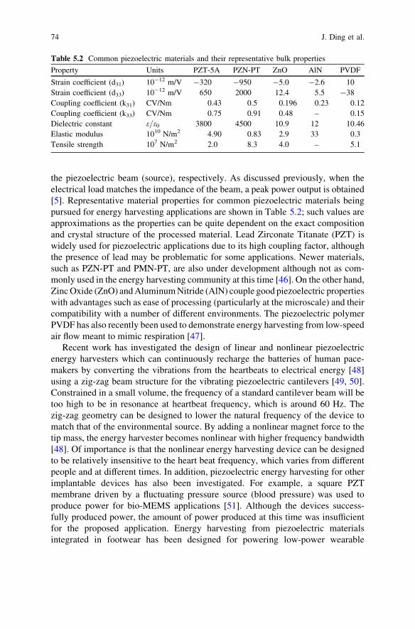
the piezoelectric beam (source), respectively. As discussed previously, when theelectrical load matches the impedance of the beam, a peak power output is obtained[5]. Representative material properties for common piezoelectric materials beingpursued for energy harvesting applications are shown in Table 5.2; such values areapproximations as the properties can be quite dependent on the exact compositionand crystal structure of the processed material. Lead Zirconate Titanate (PZT) iswidely used for piezoelectric applications due to its high coupling factor, althoughthe presence of lead may be problematic for some applications. Newer materials,such as PZN-PT and PMN-PT, are also under development although not as com-monly used in the energy harvesting community at this time [46]. On the other hand,Zinc Oxide (ZnO) and Aluminum Nitride (AlN) couple good piezoelectric propertieswith advantages such as ease of processing (particularly at the microscale) and theircompatibility with a number of different environments. The piezoelectric polymerPVDF has also recently been used to demonstrate energy harvesting from low-speedair flow meant to mimic respiration [47].
Recent work has investigated the design of linear and nonlinear piezoelectricenergy harvesters which can continuously recharge the batteries of human pace-makers by converting the vibrations from the heartbeats to electrical energy [48]using a zig-zag beam structure for the vibrating piezoelectric cantilevers [49, 50].Constrained in a small volume, the frequency of a standard cantilever beam will betoo high to be in resonance at heartbeat frequency, which is around 60 Hz. Thezig-zag geometry can be designed to lower the natural frequency of the device tomatch that of the environmental source. By adding a nonlinear magnet force to thetip mass, the energy harvester becomes nonlinear with higher frequency bandwidth[48]. Of importance is that the nonlinear energy harvesting device can be designedto be relatively insensitive to the heart beat frequency, which varies from differentpeople and at different times. In addition, piezoelectric energy harvesting for otherimplantable devices has also been investigated. For example, a square PZTmembrane driven by a fluctuating pressure source (blood pressure) was used toproduce power for bio-MEMS applications [51]. Although the devices success-fully produced power, the amount of power produced at this time was insufficientfor the proposed application. Energy harvesting from piezoelectric materialsintegrated in footwear has been designed for powering low-power wearable
Table 5.2 Common piezoelectric materials and their representative bulk properties
Property Units PZT-5A PZN-PT ZnO AlN PVDF
Strain coefficient (d31) 10-12 m/V -320 -950 -5.0 -2.6 10Strain coefficient (d33) 10-12 m/V 650 2000 12.4 5.5 -38Coupling coefficient (k31) CV/Nm 0.43 0.5 0.196 0.23 0.12Coupling coefficient (k33) CV/Nm 0.75 0.91 0.48 – 0.15Dielectric constant e=e0 3800 4500 10.9 12 10.46Elastic modulus 1010 N/m2 4.90 0.83 2.9 33 0.3Tensile strength 107 N/m2 2.0 8.3 4.0 – 5.1
74 J. Ding et al.
electronic devices [52], while the piezoelectric polymer PVDF has been applied inshoes to harvest energy from walking.
Further discussion of piezoelectric approaches to energy harvesting can befound in the excellent review articles of Beeby et al. [38], Sodano et al. [53], andAnton et al. [54], while Dutoit et al. [33] specifically discuss the design consid-erations for developing MEMS-scale piezoelectric energy harvesting devices.
In summary, vibration-based energy harvesting devices have potential appli-cations in wireless sensor networks, condition monitoring, wearable self-poweredintelligent devices, and medical implants areas. Electromagnetic and piezoelectrictransducers have been widely investigated, whereas electrostatic transducers areless commonly pursued for practical applications. Piezoelectric transducers arepromising for their simple structures and integration in MEMS using thin- or thick-film fabrication techniques, while electromagnetic transducers are not as easilyintegrated in MEMS devices due to the challenge of integrating the magnet andconductive coil within the device.
5.4 Nanofibers for Energy Harvesting Applications
It would be remiss in a chapter discussing vibration energy harvesting and itsapplication to nano- and microrobotics to not highlight some of the very excitingresearch being described in the literature with regards to the fabrication andcharacterization of multifunctional nanostructures. Nanowires are one-dimensionalmaterials with diameters of typically tens of nanometers and several microns (ormore) in length. Many different types of nanowires have been developed,including metallic (Ni, Pt, Au), semiconducting (Si, InP, GaN), and insulating(SiO2, TiO2) nanowires. Of particular interest here is the development of nano-wires based on materials that, at larger length scales, possess various propertiesthat could be useful from an energy harvesting perspective such as Zinc Oxide(ZnO) and Lead Zirconium Titanate (PZT). (See, for example, the PZT nanowiresdescribed in Chap. 2 of this book.) Here, we briefly highlight some of the recentliterature describing the development of nanofibers and nanofiber-based generatorsfor energy harvesting applications.
5.4.1 ZnO-Based Nanofibers and Nanogenerators
The piezoelectric potential of ZnO nanowires is created by the polarization of ionsin the crystal when the ZnO nanowires are elastically deformed. Unlike freemobile charges, the charges of the ions are fixed with atoms and cannot freelymove. Thus, these charges cannot be completely removed by the free carriers inthe semiconductor nanowires. For a nanowire of 50 nm in diameter and 500 nm inlength, if there is no conductivity of the nanowire, one can show that the
5 Vibration Energy Harvesting and Its Application for Nano- and Microrobotics 75
piezoelectric potential will be around 0.6 V. Considering the conductivity of ZnOwith a carrier density of 1016–1017 cm-3, the magnitude of the piezoelectricpotential will be around 0.3 V, which is sufficient to operate a Schottky diode [55].Experimental results of the piezoelectric potential were measured directly by amicrometer probe compressing the side surface of a ZnO nanowire [56].
ZnO nanowires provide a number of advantages with respect to the develop-ment of a mechanical vibration energy harvesting device [57]. ZnO nanowires canbe subjected to extremely large elastic deformation without fatigue or failure. Atthe same time, nanowires are typically free of dislocations and thus have a highresistance to fatigue due to the small diameter, which would tend to extend thelifetime of ZnO nanowire-based generators. Extremely weak mechanical distur-bances can be collected by the nanowires to produce electrical output, whichincreases the types of energy sources that can be used. In addition, ZnO is abiocompatible material that is suitable for applications in biological or medicalareas, such as powering micro/nanorobots in human body. Nanowires also providea unique opportunity for functionalization to improve the physical or chemicalproperties of the surface. Lastly, ZnO nanowires can be applied to sensors andtransducers because of its piezoelectric and semiconducting properties.
Piezoelectric nanogenerators based on ZnO nanowire arrays were first developedby Wang et al. in 2006 [56]. The efficiency of the ZnO nanowire-based generator wasestimated to be 17–30 %. The mechanism of nanowire-based generator is to couplepiezoelectric and semiconducting properties of ZnO as well as the formation of aSchottky barrier between the metal and ZnO contacts. By leveraging both piezo-electric and semiconducting properties of ZnO nanowires, ZnO nanogenerators canbe designed to convert mechanical energy into electrical energy. As highlightedbelow, two different structures of the ZnO-based nanowire nanogenerators have beenpursued: vertical nanowire and lateral nanowire integrated nanogenerators.
The lateral arrangement of ZnO nanowires appears to date to be the most commonstructure. For example, a single ZnO nanowire generator has been formed by bondingboth ends of the nanowire with metal contacts on a flexible polymer substrate [58],while as one might expect arranging an array of ZnO nanowire (also on a plasticsubstrate) resulted in a nanogenerator with larger power output [59]. For the latterexample, vertically aligned ZnO nanowires were first transferred to the plastic sub-strate to form the laterally arranged nanowires, with parallel electrode arrays thendeposited to connect the nanowires. The nanogenerator was found to produce an open-circuit voltage up to 2.03 V and a peak output power density up to 11 mW/cm3 [59].The output power is high enough to light up a commercial LED bulb, which shows thepotential practical application of the nanogenerator based on ZnO nanowires.
On the other hand, the vertical integration of ZnO nanowires provides anotherapproach to the development of nanogenerators. For example, nine vertically alignedindividual ZnO nanowires were integrated within a nanogenerator which was foundto exhibit a peak output voltage of 0.045 V and current of 2.5 nA within this singlelayer structure [60]. A vertically integrated multilayer nanogenerator can produce anoutput power density of 2.8 nW/cm2 with a peak output voltage of 0.15 V and currentof 7.2 nA [60]. Integration of individual ZnO nanogenerators into three-dimensional
76 J. Ding et al.
structures has been suggested as a means to improve the electrical power density ofthe nanogenerator. While in both cases these exciting preliminary results arepromising, significant research challenges remain in moving this technology towardfuture applications in the nano/microrobotics area.
5.4.2 PZT-Based Nanofibers and Nanogenerators
Lead Zirconate Titanate [PbZr1-xTixO3 (PZT)] is a well-known piezoelectricmaterial with a high electromechanical coupling coefficient, high dielectric con-stant, and large remnant polarization [61]. PZT exhibits a much higher dielectricconstant and piezoelectric strain coefficient than ZnO, which makes PZT apromising material for energy harvesting as shown earlier in Table 5.2. However,from recent developments in the fabrication of PZT nanofibers it has been shownthat such nanofibers may have an even higher piezoelectric voltage constant,greater bending flexibility, and higher mechanical strength than bulk PZT whichwould enable its use in nanogenerators [62]. Given these properties PZT nanofi-bers would likely generate higher voltages and power outputs than other types ofpiezoelectric materials (for a given volume and same energy source) [63].
The properties of PZT nanofibers have generated significant interest in takingadvantage of these nanofibers in the development of nanogenerators. In one suchwork, a nanogenerator based on laterally aligned electrospun PZT nanofibers oninterdigitated electrodes was demonstrated [62]. Here, the PZT nanofibers haddiameters of approximately 60 nm and lengths of 500 lm (these dimensions can tosome extent be controlled by varying the fabrication parameters used in the elec-trospinning process). The final device is covered with PDMS polymer to protect theunderlying nanowires and electrode structure. In the demonstration of the device, analternating pressure applied on the top surface of the nanogenerator is transferred tothe PZT nanofibers, such that the resulting tensile and bending stresses generate avoltage in the nanofibers. Here, an integrated electrode array is used to enhance theoutput voltage and power by combining each cell in parallel. The PZT fiber-basednanogenerator was found to experimentally produce a peak output voltage of 1.63 Vand output power of 0.03 lW with a load resistance of 6 MX [62]. While significantwork must be done to continue the development of these nanowire-based generatorstoward applications in nano- and microrobotics, the initial results demonstrated todate for both ZnO and PZT nanowires is indeed quite promising.
5 Vibration Energy Harvesting and Its Application for Nano- and Microrobotics 77
5.4.3 Other Types of Nanofibers with Applications in EnergyHarvesting
In addition to vibration energy harvesting, the development of multifunctionalnanowires is being pursued in the area of thermoelectric energy harvesting. Inpractical application, the super-thin structure of a nano/microscale thermoelectricgenerator could be integrated onto silicon chips to harvest heat energy produced inelectrical circuits. The potential ease of integration of a silicon nanowire-basedthermoelectric generator offers the prospective of an alternative way of energyharvesting. Although the output voltage of such a device would be relatively low,there may be potential applications in ultra-low, self-powered MEMS devices.
For example, a high-density silicon nanowire-based thermoelectric generator pre-pared by a top-down CMOS-compatible technique has been reported in the literature[64]. The fabricated thermoelectric generator can produce an open-circuit voltage of1.5 mV and a short-circuit current of 3.79 lA under an estimated temperature gra-dient of 0.12 K. This result is of particular interest since bulk silicon had not pre-viously been strongly considered for thermoelectric applications prior to this work;however, the efficiency of the thermoelectric modules of silicon nanowires is greatlyimproved due to the phonon boundary scattering at nanoscale [64]. The processing ofthis silicon nanowire-based thermoelectric generator is based on typical CMOS-compatible top-down processes, which is a very promising aspect of this approach.However, thermoelectric generators are based on temperature gradients (and notabsolute temperatures), and significant temperature gradients are not generallyavailable within the human body. Thus, the application of such thermoelectricnanogenerators for nano/microrobotics for biomedical applications may be limited.
In summary, nanowire-based nanogenerators provide a potential method totransfer mechanical energy in a given environment to useful levels of electricalenergy necessary to power micro/nanodevices. Both ZnO and PZT nanowires havebeen used, and the results demonstrated to date are a promising first step towardthe development of this technology for future practical applications. Due to thebiodegradable and biocompatible properties of ZnO, generators based on ZnOnanowires have a special advantage in the medical or biological arena, whereasPZT nanofibers, which have much higher dielectric constant and piezoelectricvoltage constant, can generally produce more electrical energy at this time.Nanowire technology is also being pursued to develop other energy harvestingapproaches, such as their use for thermoelectric energy harvesting highlightedbriefly here. While such work is clearly at the early stages of research, the resultsto date are quite intriguing and suggest that the idea of self-powered nano/mic-rodevices using such nanowires may be possible in the future.
78 J. Ding et al.
5.5 Conclusions and Outlook
Energy harvesting refers to the process of converting energy in a given environ-ment into a more useful form of electrical energy that can be used by the system.Because the amounts of energy which can typically be extracted in this regard arequite small, a primary challenge in the energy harvesting community is identifyingpotential applications where the amounts of energy harvested, while small, areattractive such that the benefits of an energy harvesting methodology offset theextra costs and complexity of adopting this approach. As discussed in this chapter,the power consumed by small insects can be illustrative in identifying the levels ofenergy that would be useful for nano/microrobotic applications. In particular,because the miniaturization of batteries and other electrical energy storage ele-ments has not kept pace with the advances in other areas of microsystem devel-opment, there is a concern that battery technology may represent a significantbottleneck to the realization of further reductions in the size and weight of portableelectronics. This limitation is clearly of critical concern for future micro- andnanorobotics applications. Nano- and microrobots, particularly those located ininaccessible locations within the body, are generally restricted in terms of theavailable space available for power sources, thus power scavenging approaches arean attractive means to either solely power or, alternatively, extend the operationallifetime of these systems via a trickle-charge approach.
While trends show that the term energy harvesting has recently been adapted torefer to large-scale energy sources such as solar, wind, and wave/tidal energy, inmany cases as commonly used in the literature the term suggests a kineticmechanical-to-electrical energy conversion with small levels of energy harvestedwhich, while not suitable for grid-level deployment, may find particular nicheapplications as a local, on-site power generation mechanism. When specificallyconsidering vibration energy harvesting, the three most common approaches are toutilize piezoelectric, electromagnetic, or electrostatic transduction mechanisms toconvert relative motion created by the external environment into electrical energy.A significant advantage of vibration energy harvesting is that relative motion andvibration are present in almost all environments, which is certainly the case inbiological systems of interest in this book.
Although research in this area has exploded over the past several years and sig-nificant advances have been demonstrated in the research lab, a number of areas muststill be addressed to facilitate the adaptation of this technology in practical applica-tions. For example, resonance-based vibration energy harvesting approaches requiretechniques to ensure suitable bandwidth of the device (such that appreciable levels ofenergy are harvested over a range of input vibration source frequencies) [65, 66], whilefor optimal performance and reliability, the automated tuning of a vibrational energyharvesting device is required [67]. In addition, to realize vibrational energy harvestingdevices as reliable power sources for MEMS-scale devices such as nano- and micr-orobotics requires an understanding of the lifetime stability and long-term perfor-mance of such devices. Here, a tightly coupled integration of the energy harvesting
5 Vibration Energy Harvesting and Its Application for Nano- and Microrobotics 79
component with the larger overall system is clearly required to ensure optimal systemperformance. For example, one year of resonance at 200 Hz near the yield stress of theharvester will result in 109 high amplitude, high stress deformation cycles. This sug-gests the use of resonant frequency tunability to selectively tune to a specific frequency(not necessarily resonance) to balance the power output requirements with long-termlife/performance of the harvesting device. Nonetheless, the convergence of advancesin energy harvesting methodologies and low-power electronics with the exciting recentdevelopments in the fabrication of multifunctional nanowires suggests that energyharvesting approaches show promise for the future powering of small-scale nano/microrobotics for biomedical applications.
Acknowledgments This work was supported in part by the National Science Foundation(Award No. CMMI-0846937). The authors would also like to thank Professor David Cappelleri atStevens for his contribution to this work.
References
1. Steltz E, Seeman M, Avadhanula S, Fearing (2006) RS Power electronics design choice forpiezoelectric microrobots. In: IEEE/RSJ international conference on intelligent robots andsystems, 9–15 October 2006. pp 1322–1328. doi:10.1109/IROS.2006.281897
2. Albano F, Chung MD, Blaauw D, Sylvester DM, Wise KD, Sastry AM (2007) Design of animplantable power supply for an intraocular sensor, using POWER (power optimization for wirelessenergy requirements). J Power Sour 170(1):216–224. doi:10.1016/j.jpowsour.2007.04.007
3. Freitas RA Jr (2005) Current status of nanomedicine and medical nanorobotics. J ComputTheor Nanosci 2:1–25. doi:10.1166/jctn.2005.001
4. Köhler U, Kümpers J, Ullrich M (2002) High performance nickel-metal hydride and lithium-ion batteries. J Power Sour 105(2):139–144. doi:10.1016/s0378-7753(01)00932-6
5. Cook-Chennault KA, Thambi N, Sastry AM (2008) Powering MEMS portable devices—areview of non-regenerative and regenerative power supply systems with special emphasis onpiezoelectric energy harvesting systems. Smart Mater Struct 17(4):043001. doi:10.1088/0964-1726/17/4/043001
6. Bandhauer TM, Garimella S, Fuller TF (2011) A critical review of thermal issues in lithium-ion batteries. J Electrochem Soc 158(3):R1–R25. doi:10.1149/1.3515880
7. Harb JN, LaFollette RM, Selfridge RH, Howell LL (2002) Microbatteries for self-sustainedhybrid micropower supplies. J Power Sour 104(1):46–51. doi:10.1016/s0378-7753(01)00904-1
8. Nathan M, Golodnitsky D, Yufit V, Strauss E, Ripenbein T, Shechtman I, Menkin S, Peled E(2005) Three-dimensional thin-film Li-ion microbatteries for autonomous MEMS.J Microelectromech Syst 14(5):879–885. doi:10.1109/JMEMS.2005.851860
9. Peckerar M, Dilli Z, Dornajafi M, Goldsman N, Ngu Y, Proctor RB, Krupsaw BJ, Lowy DA(2011) A novel high energy density flexible galvanic cell. Energy Environ Sci 4(5):1807–1812. doi:10.1039/C1EE01075A
10. Dohle H, Mergel J, Stolten D (2002) Heat and power management of a direct-methanol-fuel-cell (DMFC) system. J Power Sour 111(2):268–282. doi:10.1016/s0378-7753(02)00339-7
11. Steinfeld G, Maru HC, Sanderson RA (1996) High efficiency carbonate fuel cell/turbine hybridpower cycle. In: Proceedings of the 31st intersociety energy conversion engineering conference(IECEC 96), 11–16 August 1996. vol 1122, pp 1123–1127. doi:10.1109/IECEC.1996.553865
12. Heinzel A, Hebling C, Müller M, Zedda M, Müller C (2002) Fuel cells for low powerapplications. J Power Sour 105(2):250–255. doi:10.1016/s0378-7753(01)00948-x
80 J. Ding et al.
13. Stetten Fv, Kerzenmacher S, Lorenz A, Chokkalingam V, Miyakawa N, Zengerle R, Ducree J(2006) A one-compartment, direct glucose fuel cell for powering long-term medical implants.In: 19th IEEE international conference on micro electro mechanical systems, pp 934–937.doi:10.1109/memsys.2006.1627954
14. Davis F, Higson SPJ (2007) Biofuel cells—recent advances and applications. BiosensBioelectron 22(7):1224–1235. doi:10.1016/j.bios.2006.04.029
15. Kerzenmacher S, Ducrée J, Zengerle R, Stetten Fv (2008) Energy harvesting by implantableabiotically catalyzed glucose fuel cells. J Power Sour 182(1):1–17. doi:10.1016/j.jpowsour.2008.03.031
16. Kerzenmacher S, Kräling U, Metz T, Zengerle R, von Stetten F (2011) A potentiallyimplantable glucose fuel cell with Raney-platinum film electrodes for improved hydrolyticand oxidative stability. J Power Sour 196(3):1264–1272. doi:10.1016/j.jpowsour.2010.08.019
17. Sue C-Y, Tsai N-C (2012) Human powered MEMS-based energy harvest devices. ApplEnergy 93:390–403. doi:10.1016/j.apenergy.2011.12.037
18. Bell LE (2008) Cooling, heating, generating power, and recovering waste heat withthermoelectric systems. Science 321(5895):1457–1461. doi:10.1126/science.1158899
19. Carmo JP, Goncalves LM, Correia JH (2010) Thermoelectric microconverter for energyharvesting systems. IEEE Trans Industr Electron 57(3):861–867. doi:10.1109/TIE.2009.2034686
20. Bottner H, Nurnus J, Gavrikov A, Kuhner G, Jagle M, Kunzel C, Eberhard D, Plescher G,Schubert A, Schlereth KH (2004) New thermoelectric components using microsystemtechnologies. J Microelectromech Syst 13(3):414–420. doi:10.1109/JMEMS.2004.828740
21. Massaro A, De Guido S, Ingrosso I, Cingolani R, De Vittorio M, Cori M, Bertacchini A,Larcher L, Passaseo A (2011) Freestanding piezoelectric rings for high efficiency energyharvesting at low frequency. Appl Phys Lett 98(5):053502–053503. doi:10.1063/1.3551725
22. Park JC, Park JY, Lee Y-P (2010) Modeling and characterization of piezoelectric d33-mode MEMSenergy harvester. J Microelectromech Syst 19(5):1215–1222. doi:10.1109/JMEMS.2010.2067431
23. Lee BS, Lin SC, Wu WJ (2010) Fabrication and evaluation of a MEMS piezoelectricbimorph generator for vibration energy harvesting. J Mech 26(04):493–499. doi:10.1017/S172771910000469X
24. Elfrink R, Kamel TM, Goedbloed M, Matova S, Hohlfeld D, Andel YV, Schaijk RV (2009)Vibration energy harvesting with aluminum nitride-based piezoelectric devices. J MicromechMicroeng 19(9): 094005. doi:10.1088/0960-1317/19/9/094005
25. Lee BS, Lin SC, Wu WJ, Wang XY, Chang PZ, Lee CK (2009) Piezoelectric MEMSgenerators fabricated with an aerosol deposition PZT thin film. J Micromech Microeng19(6):065014. doi:10.1088/0960-1317/19/6/065014
26. Shen D, Park J-H, Noh JH, Choe S-Y, Kim S-H, Wikle Iii HC, Kim D-J (2009)Micromachined PZT cantilever based on SOI structure for low frequency vibration energyharvesting. Sens Actuators A Phys 154(1): 103–108. doi:10.1016/j.sna.2009.06.007
27. Shen D, Park J-H, Ajitsaria J, Choe S-Y, III HCW, Kim D-J (2008) The design, fabrication andevaluation of a MEMS PZT cantilever with an integrated Si proof mass for vibration energyharvesting. J Micromech Microeng 18(5): 055017. doi:10.1088/0960-1317/18/5/055017
28. Kim H, Bedekar V, Islam RA, Lee WH, Leo D, Priya S (2008) Laser-machined piezoelectriccantilevers for mechanical energy harvestingenergy harvesting. IEEE Trans UltrasonFerroelectr Freq Control 55(9):1900. doi:10.1109/TUFFC.881
29. Marzencki M, Ammar Y, Basrour S (2007) Integrated power harvesting system including aMEMS generator and a power management circuit. Sens Actuators A 145–146:363–370.doi:10.1016/j.sna.2007.10.073
30. Beeby SP, Torah RN, Tudor MJ, Glynne-Jones P, O’Donnell T, Saha CR, Roy S (2007) Amicro electromagnetic generator for vibration energy harvesting. J Micromech Microeng17(7):1257. doi:10.1088/0960-1317/17/7/007
31. Fang H-B, Liu J-Q, Xu Z-Y, Dong L, Wang L, Chen D, Cai B-C, Liu Y (2006) Fabricationand performance of MEMS-based piezoelectric power generator for vibration energyharvesting. Microelectron J 37(11):1280–1284. doi:10.1016/j.mejo.2006.07.023
5 Vibration Energy Harvesting and Its Application for Nano- and Microrobotics 81
32. Jeon YB, Sood R, Jeong Jh, Kim SG (2005b) MEMS power generator with transverse modethin film PZT. Sens Actuators A 122(1):16–22. doi:10.1016/j.sna.2004.12.032
33. Dutoit NE, Wardle BL, Kim S-G (2005) Design considerations for MEMS-scale piezoelectricmechanical vibration energy harvesters. Integr Ferroelectr Int J 71(1):121–160. doi:10.1080/10584580590964574
34. Williams CB, Yates RB (1996) Analysis of a micro-electric generator for microsystems. SensActuators A 52(1–3):8–11. doi:10.1016/0924-4247(96)80118-x
35. Glynne-Jones P, Tudor M, Beeby S, White N (2004) An electromagnetic, vibration-poweredgenerator for intelligent sensor systems. Sens Actuators A 110(1–3):344–349. doi:10.1016/j.sna.2003.09.045
36. Saha CR, O’Donnell T, Loder H, Beeby S, Tudor J (2006) Optimization of an electromagneticenergy harvesting device. IEEE Trans Magn 42(10):3509–3511. doi:10.1109/TMAG.2006.879447
37. Serre C, Pérez-Rodríguez A, Fondevilla N, Morante JR, Montserrat J, Esteve J (2007)Vibrational energy scavenging with Si technology electromagnetic inertial microgenerators.Microsyst Technol 13(11–12):1655–1661. doi:10.1007/s00542-006-0338-1
38. Beeby SP, Tudor MJ, White NM (2006) Energy harvesting vibration sources for microsystemsapplications. Meas Sci Technol 17(12):R175. doi:10.1088/0957-0233/17/12/R01
39. Roundy S (2005) On the effectiveness of vibration-based energy harvesting. J Intell MaterSyst Struct 16(10):809–823. doi:10.1177/1045389x05054042
40. Meninger S, Mur-Miranda JO, Amirtharajah R, Chandrakasan AP, Lang JH (2001)Vibration-to-electric energy conversion. IEEE Trans Very Large Scale Integr (VLSI) Syst9(1): 64–76. doi:10.1109/92.920820
41. Roundy S, Wright PK, Pister KSJ (2002) Micro-electrostatic vibration-to-electricityconverters. In: ASME 2002 international mechanical engineering congress and exposition(IMECE2002). New Orleans, Louisiana, pp 487–496. doi:10.1115/IMECE2002-39309
42. Chiu Y, Kuo C-T, Chu Y-S (2007) MEMS design and fabrication of an electrostaticvibration-to-electricity energy converter. Microsyst Technol 13(11):1663–1669. doi:10.1007/s00542-006-0348-z
43. Bartsch U, Trautmann A, Ruther P, Gaspar J, Paul O (2007) Electrostatic transducers formicro energy harvesting based on SOI technology. In: Solid-state sensors, actuators andmicrosystems conference. pp 141–144. doi:10.1109/SENSOR.2007.4300091
44. Tashiro R, Kabei N, Katayama K, Ishizuka Y, Tsuboi F, Tsuchiya K (2000) Development ofan electrostatic generator that harnesses the motion of a living body: use of a resonantphenomenon. JSME Int J Ser C 43(4):916–922
45. Han J, Von Jouanne A, Le T, Mayaram K, Fiez TS (2004) Novel power conditioning circuitsfor piezoelectric micro power generators. In: IEEE applied power electronics conference andexposition—APEC. pp 1541–1546. doi:10.1109/APEC.2004.1296069
46. Ivan IA, Rakotondrabe M, Agnus J, Bourquin R, Chaillet N, Lutz P, Poncot JC, Duffait R, BauerO (2010) Comparative material study between PZT ceramic and newer crystalline PMN-PT andPZN-PT materials for composite bimorph actuators. Rev Adv Mat Sci 24(1–2):1–9
47. Sun C, Shi J, Bayerl DJ, Wang X (2011) PVDF microbelts for harvesting energy fromrespiration. Energy Environ Sci 4(11):4508–4512. doi:10.1039/C1EE02241E
48. Karami MA, Inman DJ (2012a) Powering pacemakers from heartbeat vibrations using linear andnonlinear energy harvesters. Appl Phys Lett 100(4):042901–042904. doi:10.1063/1.3679102
49. Karami MA, Inman DJ (2011) Analytical modeling and experimental verification of thevibrations of the zigzag microstructure for energy harvesting. J Vib Acoust 133(1):011002–011010. doi:10.1115/1.4002783
50. Karami MA, Inman DJ (2012b) Parametric study of zigzag microstructure for vibrational energyharvesting. J Microelectromech Syst 21(1):145–160. doi:10.1109/JMEMS.2011.2171321
51. Ramsay MJ, Clark WW (2001) Piezoelectric energy harvesting for bio-MEMS applications.In: McGowan A-MR (ed) Smart structures and materials 2001: industrial and commercialapplications of smart structures technologies SPIE, pp 429–438. doi:10.1117/12.429684
82 J. Ding et al.
52. Rocha JG, Goncalves LM, Rocha PF, Silva MP, Lanceros-Mendez S (2010) Energyharvesting from piezoelectric materials fully integrated in footwear. IEEE Trans Ind Electron57(3). doi:10.1109/TIE.2009.2028360
53. Sodano HA, Inman DJ, Park G (2004) A review of power harvesting from vibration usingpiezoelectric materials. Shock Vib Dig 36(3):197–205. doi:10.1177/0583102404043275
54. Anton SR, Sodano HA (2007) A review of power harvesting using piezoelectric materials(2003–2006). Smart Mater Struct 16(3):R1. doi:10.1088/0964-1726/16/3/R01
55. Gao Y, Wang ZL (2009) Equilibrium potential of free charge carriers in a bent piezoelectricsemiconductive nanowire. Nano Lett 9(3):1103–1110. doi:10.1021/nl803547f
56. Wang ZL, Song J (2006) Piezoelectric nanogenerators based on zinc oxide nanowire arrays.Science 312(5771):242–246. doi:10.1126/science.1124005
57. Wang ZL (2008) Towards self-powered nanosystems: from nanogenerators tonanopiezotronics. Adv Funct Mater 18(22):3553–3567. doi:10.1002/adfm.200800541
58. Yang R, Qin Y, Dai L, Wang ZL (2009) Power generation with laterally packagedpiezoelectric fine wires. Nat Nanotechnol 4(1):34–39. doi:10.1038/nnano.2008.314
59. Zhu G, Yang R, Wang S, Wang ZL (2010a) Flexible high-output nanogenerator based onlateral ZnO nanowire array. Nano Lett 10(8):3151–3155. doi:10.1021/nl101973h
60. Yu A, Li H, Tang H, Liu T, Jiang P, Wang ZL (2011) Vertically integrated nanogeneratorbased on ZnO nanowire arrays. Phys Status Solidi Rapid Res Lett 5(4):162–164. doi:10.1002/pssr.201105120
61. Xu S, Shi Y, Kim S-G (2006) Fabrication and mechanical property of nano piezoelectricfibres. Nanotechnology 17(17):4497. doi:10.1088/0957-4484/17/17/036
62. Chen X, Xu S, Yao N, Shi Y (2010) 1.6 V nanogenerator for mechanical energy harvestingusing PZT nanofibers. Nano Let 10(6):2133–2137. doi:10.1021/nl100812k
63. Chen X, Xu S, Yao N, Xu W, Shi Y (2009) Potential measurement from a single leadzirconate titanate nanofiber using a nanomanipulator. Appl Phys Lett 94(25):253113–253113.doi:10.1063/1.3157837
64. Li Y, Buddharaju K, Singh N, Lo GQ, Lee SJ (2011) Chip-level thermoelectric powergenerators based on high-density silicon nanowire array prepared with top-down CMOStechnology. Electron Device Let 32(5):674–676. doi:10.1109/LED.2011.2114634
65. Zhu D, Tudor MJ, Beeby SP (2010b) Strategies for increasing the operating frequency rangeof vibration energy harvesters: a review. Meas Sci Technol 21(2):022001. doi:10.1088/0957-0233/21/2/022001
66. Challa VR, Prasad MG, Shi Y, Fisher FT (2008) A vibration energy harvesting device withbidirectional resonance frequency tunability. Smart Mater Struct 17(1):015035. doi:10.1088/0964-1726/17/01/015035
67. Challa VR, Prasad MG, Fisher FT (2011) Towards an autonomous self-tuning vibrationenergy harvesting device for wireless sensor network applications. Smart Mater Struct20(2):025004. doi:10.1088/0964-1726/20/2/025004
5 Vibration Energy Harvesting and Its Application for Nano- and Microrobotics 83