Embed Size (px)
Citation preview

5-1
Chapter 5
������������� ���� ������� ��
� �������
������� �������
This chapter describes technologies for treating former MGP residues. Thesetechnologies have either been proven successful and cost effective or are newand promising for use at former MGP sites. The technologies described
below destroy or encapsulate MGP residuals in the vadose zone, reducing oreliminating the threat that chemicals from these materials will reach groundwateror human populations and thus limiting or reducing the responsible party’sliability. (This is in contrast to past methods of disposal that often involvedsending wastes to landfills where the responsible parties continue to bear long-term responsibility for the waste’s environmental and health effects.)
The technologies discussed in this chapter are summarized in the following table.Although each technology is discussed independently, multiple treatmenttechnologies may be applied at a site to address the various chemical components.For example, soil vapor extraction (SVE) may be applied at a former MGP site toremediate the volatile components of the MGP residues concurrent with or prior toin situ stabilization (which will treat the heavier, less mobile chemicalcompounds). Multiple technologies applied concurrently or sequentially are oftenreferred to as treatment trains, and are often formed to address an overall siteremediation.
The costs provided in this section are based on limited data and are dynamic.Many variables will affect the cost of a remediation technology as applied to aspecific site or set of sites. The cost information provided herein reflects an order-of-magnitude guide to cost, and is provided on an informational basis.
This document does not address the treatment of NAPLs or MGP contaminants ingroundwater. These issues may be addressed in a future volume of this document.However, remediation at a site should address all the site’s contaminants,including those present in both soil and groundwater.
������������������ ���� ������� ���� �������
The following sections contain specific information pertaining to each of thetechnologies for treating residuals and contaminated soil from former MGP sites.

5-2
Sou
rce
Mat
eria
l Tre
atm
ent T
ech
nol
ogie
s
Nam
eD
escr
iptio
nB
enef
itsLi
mita
tions
App
roxi
mat
eCo
st *
Co-B
urni
ngC
ombu
stio
n of
MG
P re
sidu
es w
ithco
al in
util
ity b
oile
rs a
nd c
emen
tki
lns.
• R
ecyc
les
was
tes
• D
estro
ys o
rgan
ic c
onta
min
ants
• C
ost e
ffect
ive
• Lo
ng-te
rm im
pact
s on
boi
ler e
ffici
ency
,m
aint
enan
ce, a
nd o
pera
tion
is u
nkno
wn
$44-
$309
/ton
Ther
mal
Tre
atm
ent P
roce
sses
Ex S
itu T
herm
al D
esor
ptio
nD
esor
ptio
n an
d/or
des
truct
ion
ofor
gani
c co
ntam
inan
ts in
exc
avat
edso
il by
hea
ting.
• D
emon
stra
ted
PAH
and
org
anic
cont
amin
ant r
educ
tion
• M
ovea
ble
units
ava
ilabl
e fo
r ons
itetre
atm
ent
• H
azar
dous
leve
ls o
f con
tam
inan
ts m
ay n
otbe
acc
epte
d at
offs
ite fa
cilit
ies
• W
et o
r sat
urat
ed m
edia
requ
ires
dew
ater
ing
prio
r to
treat
men
t•
Soil
with
hig
h or
gani
c co
nten
t is
unsu
itabl
efo
r tre
atm
ent
• Ai
r em
issi
ons
cont
rol m
ay b
e re
quire
d
$100
-$20
0/to
n
In S
itu T
herm
al P
roce
sses
Dyn
amic
Und
ergr
ound
Stri
ppin
g(D
US)
Inje
ctio
n of
ste
am in
to s
ubsu
rface
cont
amin
ants
to v
olat
ilize
and
mob
ilize
cont
amin
ants
.
• M
inim
al d
isru
ptio
n to
site
ope
ratio
ns•
Rem
oves
con
tam
inan
ts u
nder
exi
stin
gst
ruct
ures
• W
orks
wel
l und
er w
ide
rang
e of
soi
lty
pes
• U
tility
cos
ts m
ay b
e hi
gh•
Suffi
cien
t con
tam
inan
t mas
s m
ay n
ot b
ere
mov
ed d
urin
g tre
atm
ent
$110
/cy
In S
itu T
herm
al D
esor
ptio
n (IS
TD)
Soil
heat
ing
via
in-w
ell h
eate
r or
elec
trode
s to
vap
oriz
e/vo
latil
ize
fluid
s an
d co
ntam
inan
ts.
• M
inim
al d
isru
ptio
n to
site
ope
ratio
ns•
Rem
oves
con
tam
inan
ts u
nder
exi
stin
gst
ruct
ures
• W
orks
wel
l und
er w
ide
rang
e of
soi
lty
pes
• U
tility
cos
ts m
ay b
e hi
gh•
Wor
ks b
est i
n un
satu
rate
d co
nditi
ons
$120
-$30
0/cy
Con
tain
ed R
ecov
ery
of O
ilyW
aste
s (C
RO
W)
Hot
wat
er fl
ushi
ng/d
ispl
acem
ent
and
extra
ctio
n of
sub
surfa
ceco
ntam
inan
ts.
• M
inim
al d
isru
ptio
n to
site
ope
ratio
ns•
Rem
oves
con
tam
inan
ts u
nder
exi
stin
gst
ruct
ures
• W
orks
wel
l und
er w
ide
rang
e of
soi
lty
pes
• U
tility
cos
ts m
ay b
e hi
gh•
Suffi
cien
t con
tam
inan
t mas
s m
ay n
ot b
ere
mov
ed d
urin
g tre
atm
ent
N/A

5-3
Sou
rce
Mat
eria
l Tre
atm
ent T
ech
nol
ogie
s, c
onti
nu
ed
Nam
eD
escr
iptio
nB
enef
itsLi
mita
tions
App
roxi
mat
eCo
st *
Asph
alt B
atch
ing
Col
d-M
ix A
spha
lt Ba
tchi
ngEn
caps
ulat
ion
of c
onta
min
ant b
ybl
endi
ng re
sidu
es, w
et a
ggre
gate
and
asph
alt e
mul
sion
at a
mbi
ent
tem
pera
ture
.
• R
euse
s m
ater
ials
• Im
mob
ilizes
PAH
s•
Viab
le tr
eatm
ent t
echn
olog
y fo
r coa
l tar
s
• C
urin
g tim
es c
an b
e af
fect
ed b
y te
mpe
ratu
re•
Not
via
ble
for f
ine-
grai
ned
mat
eria
ls (e
.g.,
clay
s)•
Phys
ical
pro
perti
es o
f fin
al p
rodu
ct n
ot a
lway
sap
prop
riate
for t
raffi
c re
use
$40-
$70/
ton
Hot
-Mix
Asp
halt
Batc
hing
Enca
psul
atio
n of
con
tam
inan
t by
blen
ding
resi
dues
, wet
agg
rega
tean
d as
phal
t em
ulsi
on a
t hig
hte
mpe
ratu
re.
• R
euse
s m
ater
ials
• Im
mob
ilizes
PAH
s•
Viab
le tr
eatm
ent t
echn
olog
y fo
r coa
l tar
s
• C
urin
g tim
es c
an b
e af
fect
ed b
y te
mpe
ratu
re•
Not
via
ble
for f
ine-
grai
ned
mat
eria
ls (e
.g.,
clay
s)•
Phys
ical
pro
perti
es o
f fin
al p
rodu
ct n
ot a
lway
sap
prop
riate
for t
raffi
c re
use
$40-
$70/
ton
Bior
emed
iatio
n/ C
hem
ical
ly E
nhan
ced
Bior
emed
iatio
n
Ex S
itu B
iore
med
iatio
n
Land
farm
ing
Des
truct
ion
of o
rgan
ic c
ompo
unds
in c
onta
min
ated
soi
l by
mic
roor
gani
sms.
Tre
atm
ent o
ccur
son
line
d be
ds d
urin
g co
ntam
inat
edso
il til
ling
and
irrig
atio
n.
• Sh
orte
r tre
atm
ent p
erio
ds th
an in
situ
bior
emed
iatio
n al
tern
ativ
es•
Red
uces
con
tam
inan
t con
cent
ratio
ns
• N
ot e
ffect
ive
for h
ighe
r mol
ecul
ar-w
eigh
thy
droc
arbo
ns•
May
be
slow
er th
an a
ltern
ativ
e tre
atm
ent
tech
nolo
gies
$75/
cy e
xclu
sive
of
lab
and
pilo
t stu
dies
Biop
iles
Des
truct
ion
of o
rgan
ic c
ompo
unds
in c
onta
min
ated
soi
l by
mic
roor
gani
sms.
Tre
atm
ent o
ccur
sth
roug
h so
il am
endm
ent a
ndst
ockp
iling.
• Sh
orte
r tre
atm
ent p
erio
ds th
an in
situ
bior
emed
iatio
n al
tern
ativ
es•
Red
uces
con
tam
inan
t con
cent
ratio
ns
• N
ot e
ffect
ive
for h
ighe
r mol
ecul
ar-w
eigh
thy
droc
arbo
ns•
May
be
slow
er th
an a
ltern
ativ
e tre
atm
ent
tech
nolo
gies
$100
-$20
0/cy
excl
usiv
e of
lab
and
pilo
t stu
dies
Bior
eact
orD
estru
ctio
n of
org
anic
com
poun
dsin
con
tam
inat
ed s
oil b
ym
icro
orga
nism
s. T
reat
men
t occ
urs
in a
n en
clos
ed re
acto
r ves
sel.
• Sh
orte
r tre
atm
ent p
erio
ds th
an in
situ
bior
emed
iatio
n al
tern
ativ
es•
Red
uces
con
tam
inan
t con
cent
ratio
ns
• N
ot e
ffect
ive
for h
ighe
r mol
ecul
ar-w
eigh
thy
droc
arbo
ns•
May
be
slow
er th
an a
ltern
ativ
e tre
atm
ent
tech
nolo
gies
$216
/cy
excl
usiv
e of
lab
and
pilo
t stu
dies
In S
itu B
iore
med
iatio
n/Bi
oven
ting
Des
truct
ion
of o
rgan
ic c
ompo
unds
in s
ubsu
rface
con
tam
inat
ed s
oil b
ym
icro
orga
nism
s.
• G
ener
ally
inex
pens
ive
• M
inim
al d
isru
ptio
n of
exi
stin
g op
erat
ions
• R
emov
es c
onta
min
ants
from
und
erex
istin
g st
ruct
ures
• Ve
rific
atio
n of
des
truct
ion
is s
omet
imes
diff
icul
t•
Not
effe
ctiv
e fo
r hig
her m
olec
ular
-wei
ght
hydr
ocar
bons
• Tr
eatm
ent u
nifo
rmity
unc
erta
in b
ecau
se o
fsu
bsur
face
var
iabl
es
$10-
$70/
cy e
xclu
sive
of la
b an
d pi
lot
stud
ies

5-4
Sou
rce
Mat
eria
l Tre
atm
ent T
ech
nol
ogie
s, c
onti
nu
ed
Nam
eD
escr
iptio
nB
enef
itsLi
mita
tions
App
roxi
mat
eCo
st *
Cont
ainm
ent
Con
tain
men
t or c
appi
ng o
fco
ntam
inat
ed s
oil t
o pr
even
t or
sign
ifica
ntly
redu
ce c
onta
min
ant
mig
ratio
n an
d to
pre
vent
hum
an a
ndan
imal
exp
osur
e.
• Q
uick
inst
alla
tion
• D
oes
not r
equi
re s
oil e
xcav
atio
n•
Prev
ents
ver
tical
infil
tratio
n of
wat
er•
Prev
ents
hum
an a
nd a
nim
al e
xpos
ure
• C
onta
ins
was
tes;
doe
s no
t red
uce
cont
amin
ant
conc
entra
tion
• R
equi
res
oper
atio
n an
d m
aint
enan
ce p
rogr
am•
Typi
cally
requ
ires
inst
itutio
nal c
ontro
ls (e
.g.,
deed
rest
rictio
n)
$45,
000-
$170
,000
/ac
Stab
iliza
tion/
Solid
ifica
tion
In S
itu S
/SEn
caps
ulat
ion
of c
onta
min
ant b
y in
situ
ble
ndin
g w
ith c
hem
ical
bin
ders
to im
mob
ilize
cont
amin
ant o
fco
ncer
n.
• Im
mob
ilizes
con
tam
inan
ts•
Neu
traliz
es s
oil
• Im
prov
es b
earin
g ca
paci
ty o
r she
arst
reng
th o
f tre
ated
are
a
• Po
ssib
le le
achi
ng o
f vol
atile
or m
obile
cont
amin
ants
• C
reat
ion
of c
oncr
ete-
like
mat
eria
l in
subs
urfa
ce•
Effe
ctiv
e in
situ
mix
ing
may
be
diffi
cult
$40-
$60/
cy in
shal
low
app
licat
ions
,ex
clus
ive
of la
b an
dpi
lot s
tudi
es
Ex S
itu S
/SEn
caps
ulat
ion
of c
onta
min
ants
inex
cava
ted
soil
by b
lend
ing
with
chem
ical
bin
ders
to im
mob
ilize
cont
amin
ant o
f con
cern
.
• Im
mob
ilizes
con
tam
inan
ts•
Perfo
rman
ce d
epen
dent
upo
n ch
emic
alco
mpo
sitio
n of
was
tes
• Lo
ng-te
rm im
mob
ilizat
ion
of c
onta
min
ant m
aybe
affe
cted
by
envi
ronm
enta
l con
ditio
ns
$100
/ton
excl
usiv
eof
lab
and
pilo
tst
udie
s
Soil
Was
hing
Phys
ical
/che
mic
al p
roce
ss fo
rsc
rubb
ing
soils
ex
situ
to re
mov
eco
ntam
inan
ts.
• H
igh
degr
ee o
f cer
tain
ty re
gard
ing
treat
men
t per
form
ance
• M
ater
ial h
andl
ing
poss
ibly
exp
ensi
ve•
Effe
ctiv
enes
s lim
ited
by c
ompl
ex w
aste
mix
ture
s an
d hi
gh h
umic
con
tent
$170
/ton
Soil
Vapo
r Ext
ract
ion
Extra
ctio
n of
air
from
sub
surfa
ce to
rem
ove
vola
tile
com
poun
ds fr
omva
dose
zon
e so
ils.
• R
emov
es c
onta
min
ant f
rom
und
erex
istin
g st
ruct
ures
• Pr
omot
es in
situ
bio
degr
adat
ion
• W
ell e
stab
lishe
d tre
atm
ent t
echn
olog
y•
Min
imal
dis
rupt
ion
to s
ite o
pera
tions
• N
ot e
ffect
ive
for l
ow-v
olat
ility
com
poun
ds•
May
not
be
effe
ctiv
e in
are
as w
ith w
ater
tabl
essh
allo
wer
than
5 to
10
feet
bgs
or i
n fin
e-gr
ain
soils
• Li
mite
d ef
fect
iven
ess
on p
ools
of c
onta
min
ants
$2-$
450/
cy
* App
roxi
mat
e co
sts
do n
ot in
clud
e co
st o
f exc
avat
ion,
tran
spor
tatio
n, m
ater
ial h
andl
ing,
etc
.

&KDSWHU �
7HFKQRORJLHV IRU 6RXUFH 0DWHULDO 7UHDWPHQW
5-5
������������ ���
7HFKQRORJ\ 'HVFULSWLRQ
Co-burning is the process by which MGP residues such as coal tar and tar-contaminated soils are combusted along with coal in utility boilers. Developed bythe Edison Electric Institute’s (EEI) subcommittee for MGP sites with technicalsupport from the Electric Power Research Institute (EPRI), this technology blendsremediation waste recovered during site excavation with coal so as to render itnonhazardous for co-burning in utility boilers. EPRI also developed a samplingapproach that is consistent with EPA test methods for characterizing soils andwastes and for developing blending ratios for treating soils. This strategy isintended to ensure that only nonhazardous MGP wastes are co-burned in utilityboilers, and allows utilities to burn this waste without entering the RCRAhazardous waste permit program or paying the high cost of commercialincineration (EPRI, 1995).
2SHUDWLRQDO &RQVLGHUDWLRQV
Utilities have co-burned MGP site wastes in a variety of utility boilers, includingstokers, cyclones, and those fired by pulverized coal. Preparation consists ofscreening waste to remove oversized material and rendering the materialnonhazardous under RCRA if necessary (GRI, 1996). MGP materials are typicallyblended with coal feedstock in the range of 5 to 10 percent coal or wastes. Co-burning increases the amount of ash requiring management. For example, a 10percent co-burning mixture doubles the amount of ash generated by a boiler (GRI,1996).
$SSOLFDWLRQV DQG &RVW
As of 1996, co-burning was used as part of full-scale remediation at five MGP sites;four other demonstration tests have been completed (GRI, 1996). Media that havebeen treated include coal tars, purifier box wastes, and contaminated soils. Co-burning is currently offered as a commercial service by one utility in the northeastUnited States. The cost of co-burning in a case study in Rochester, New York,ranged from $44 to $142 per ton for soil and from $134 to $309 per ton for tars.
The utility company currently offering co-burning charges a tipping fee ofapproximately $90 per ton to incorporate the MGP site residuals into its boilerfeed, but this cost does not include any preprocessing, transportation, or analyticalwork necessary for disposal (GRI, 1996).
%HQHILWV
� Reuses/recycles waste into a usable product
� Has demonstrated technical feasibility to destroy organic contaminants
� Allows utilities to expedite flexible, cost-effective remediation at MGP sites
/LPLWDWLRQV
� Long-term impact of co-burning on boiler efficiency, maintenance, andoperation is unknown

&KDSWHU �
7HFKQRORJLHV IRU 6RXUFH 0DWHULDO 7UHDWPHQW
5-6
&DVH 6WXGLHV
5RFKHVWHU� 1HZ <RUN
Rochester Gas and Electric (RG&E) with the assistance of EPRI, the Gas ResearchInstitute (GRI) and the New York Gas Group evaluated co-burning for use at theirplant. RG&E operates an 80-megawatt, tangentially fired, pulverized coal unitbuilt in 1959 by Combustion Engineering. It is located on the same site as theformer West Station MGP. Residues in the form of “neat” coal tar and soil withmajor amounts of rock, brick, coke, concrete, and other demolition debris remainat the West Station site. The soil contains from 40,000 to 70,000 ppm of PAHs.Although preprocessing was needed to remove large rocks and other debris, thetar and soil were easily blended with coal to make two distinct fuel products. Onefuel product contained 4 percent tar, and the other contained 5 percent soil, withthe balance in both cases made up of coal.
The test burn program contained a series of inspection and evaluation protocolsdirected at monitoring the effects of these mixed fuels on the boiler and ancillarysystems. In a program that lasted approximately 12 weeks (4 weeks of which werededicated to actual co-burning), the boiler performed without significantperformance losses, PAH removal efficiency exceeded 99 percent, electrostaticprecipitator performance was unchanged, and emissions appeared unaffected (airemissions were actually significantly reduced for certain parameters).
Two factors that arose in this demonstration could greatly affect the feasibility andcost of co-burning. The first factor is that the state environmental agency requiredash leachate to meet drinking water standards before it would grant RG&Epermission to reuse the ash. Because drinking water standards are set below themethod detection limit for many parameters, the ash could not meet thesestandards, and the state denied permission to reuse it. If not resolved, thisprohibition on reuse will add more than $50 per ton to the cost of the residues tobe treated. (One bottom ash sample also showed PAH concentrations of 800 ppb,attributed to spillover from the mill reject system.) The second factor that affectsco-burning is the potential physical damage to a boiler using this technology. Millabrasion was measured during the test and one measurement indicated a rate ofwear about eight times that from processing ordinary coal. If this measurementand test are representative, maintenance costs of co-burning could increaseproportionally.
&RQWDFW
Kevin L. Hylton, Rochester Gas and Electric Corporation, (716) 546-2700
*UHHQYLOOH� 6RXWK &DUROLQD
Co-burning of MGP residues was demonstrated in a pulverized-coal, tangentiallyfired utility boiler at the Duke Power Company in South Carolina. Theremediation site was the Broad Street MGP in Greenville, where a 1.2-acre,carbureted water gas plant operated from 1875 until 1951. The co-burn facility wasDuke Power Company’s Lee Steam Station, located in Pelzer, South Carolina. TheMGP residues were co-burned in unit No. 3, which has a capacity of 175 MW andwas constructed in 1956.

&KDSWHU �
7HFKQRORJLHV IRU 6RXUFH 0DWHULDO 7UHDWPHQW
5-7
The project’s remediation goals were to prepare the site for future sale as anindustrial/commercial property. A cleanup level of 200 ppm total PAHs wasrequired. The matrix treated consisted of soil impacted with MGP residues. Priorto co-burning, soil was screened to ½ inch and then blended with coal at amaximum rate of 5 percent. Plant operations preferred a 2 percent blend.
This was a full-scale operation. The plant had a permit for 19,000 tons of soil peryear, but the actual amount treated was estimated at 3,000 tons per year. Beforetreatment, total PAH concentrations in site soils ranged up to 1,600 ppm. Aftertreatment, BTEX and PAH concentrations were below the detection limit in allbottom ash and fly ash samples. Stack gas concentrations were the same as whenco-burning was not taking place. The project is now complete, with 3,000 tons ofmaterial treated and managed; a destruction and removal efficiency (DRE) of 100percent was obtained. No additional co-burns of MGP residues are planned at thistime.
&RQWDFWV
Ralph Roberts, Duke Power Company, (704) 875-5536, [email protected] Lori Murtaugh, South Carolina Department of Health and Environmental Control,(803) 734-4668
,OOLQRLV 3RZHU &RPSDQ\�,OOLQRYD 5HVRXUFH 5HFRYHU\
Illinois Power and Illinova Resource Recovery, Inc. operate a commercial wastemanagement facility at Illinois Power’s Baldwin Power Station. The program isdesigned to co-burn MGP remediation wastes from the utility industry. Thesewastes are blended with coal and burned in the Baldwin Power Station’s twocyclone boilers.
Power Station DescriptionThe Baldwin Power Station is located outside the village of Baldwin, Illinois,approximately one hour southeast of St. Louis, Missouri. The area is primarilyrural agricultural property.
Two 600-megawatt cyclone boilers are utilized to co-burn remediation wastes. Thecyclone units are especially suited to burning these wastes due to the fact thatmaterials can be fed at up to a one-inch size, without the need of pulverization to200 mesh as is required in some coal-fired power plants. In addition, 90 percent ofthe ash generated from cyclone boilers is in the form of a vitrified, inert slagmaterial. All this slag is sold commercially as sandblast grit and roofing shingleaggregate. Both power station boilers are base-load units, meaning that theyoperate 24 hours per day, 7 days per week at full-load. This allows co-burning tobe conducted on a steady basis and maximizes the capacity of the program. TheBaldwin units are equipped with electrostatic precipitators and continuousemission monitors. The units are fueled with Illinois Basin coal.
Waste Management FacilityA dedicated waste management facility has been constructed at the BaldwinPower Station specifically designed to receive, store, and process remediationwastes. All waste storage and processing activities are conducted in a 30,000

&KDSWHU �
7HFKQRORJLHV IRU 6RXUFH 0DWHULDO 7UHDWPHQW
5-8
square foot water-tight concrete and steel containment pad. The containment padcan store 8,000 cubic yards of contaminated soil. Baldwin is allowed to load wasteat a rate of 5 percent of the coal loaded daily. This corresponds to approximately450 tons per day capacity. Baldwin has demonstrated a 300-ton-per-day sustainedrate capacity. The practical annual capacity is currently about 100,000 tons peryear. The waste materials are delivered by dump trailer and off-loaded directlyinto the containment pad. The materials are then crushed, screened, and blendedwith coal to produce a final product that is homogenous, less than two inches insize, and free of metal, plastic and other unprocessable debris. Rock, gravel, andmasonry are accepted and crushed with the other materials and burned in theboilers. The processed material is delivered to the power plant coal conveyorsusing an enclosed conveyor system.
Environmental PermitsThe Baldwin facility is fully permitted by the Illinois Environmental ProtectionAgency as a commercial waste treatment and storage facility. Solid waste permitslimit types and quantities of acceptable waste, and define the managementpractices, documentation and inspection requirements, and quality controlprocedures. Water discharge permits require collection, treatment, and analysis ofrunoff water prior to discharge to the environment. Air permits limit the amountof dust generated and the emissions from the boiler stacks. The IllinoisEnvironmental Protection Agency has been very supportive of the program as asafe and effective means of permanently eliminating the hazards and liabilitiesassociated with these wastes, which previously were disposed of in landfillsalmost exclusively. Three USEPA Regions have approved the operation for receiptof coal tar and petroleum contaminated soil and debris for federal Superfund sites.
Operating HistoryA test burn in March of 1994 convinced Illinois Power that the power plantsystems could handle the contaminated soils effectively with acceptable impacts toboiler operations and efficiencies. The costs, however, indicated that the processwould not be cost effective for only Illinois Power’s quantities of waste. It wasdetermined that a commercial operation could be supported by the quantities ofwaste market, thereby providing the economies of scale required to make theproject feasible.
Since the initiation of operations in June of 1996, over 135,000 tons of waste havebeen accepted and treated at Baldwin. Materials have been received from as far as1,200 miles away. Baldwin has been an integral contributor to the remediation ofover 40 contaminated sites for more than 20 customers.
��������� ����� ��������� ����
Thermal desorption is a treatment technology in which organic chemicalconstituents contained within a contaminated soil matrix volatilize as a result ofheating. The volatilized constituents are then extracted from nonvolatile materials,such as soil, and treated prior to release. Thermal desorption can be grouped intoin situ and ex situ practices. Both technologies are described below.

&KDSWHU �
7HFKQRORJLHV IRU 6RXUFH 0DWHULDO 7UHDWPHQW
5-9
������� ([ 6LWX 7KHUPDO 'HVRUSWLRQ
7HFKQRORJLFDO 'HVFULSWLRQ
Full-scale thermal desorption has been successfully used to remediate soilscontaining MGP wastes (e.g., lampblack, coal tar) since the early 1980s, achievingconcentration reductions of more than 98 percent for TPHs, BTEX compounds,PAHs, and cyanide. Thermal desorption has been used in many non-MGPapplications, and is a common remediation technology for MGP sites. Thetechnology can be applied on site with a mobile unit or at an off-site facility. Belowis a photograph of a thermal desorption unit.
Thermal desorption uses temperatures ranging from 400°F to 1,200°F to desorbchemicals from the soil. Soil is fed into a material dryer where heated air causeschemicals to volatilize. In general, temperatures between 200° F and 900°F arerequired to desorb VOCs and many PAH compounds. Higher temperatures (up to1,200°F) are required to desorb high-molecular-weight PAHs (Barr, 1996). Afterchemicals in the offgas are treated, the cleaned air is vented to the atmosphere.The dry, hot soil is then discharged to a pug mixer where water is introduced toreduce dust and lower the soil temperature. The quenched soil is discharged andtransported to a stockpile. Each day’s production volume of soil is held separatelywhile residual concentrations are determined. The treated soil is then returned tothe excavation, transported to an off-site facility for disposal, or reused at adifferent location. A typical thermal desorption unit can treat approximately 8 to45 tons per hour, depending on soil conditions (e.g., water content, wasteconcentrations, etc.) and the size of the dryer unit used.
2SHUDWLRQDO &RQVLGHUDWLRQV
The thermal desorber’s operational characteristics depend on soil type andproperties, contaminant type and concentrations, moisture content, organicmaterial content, pH, compound volatility, and temperature and residence timeduring drying. This technology may require a pilot test demonstration. Blending isrecommended to reduce variations in organic concentrations.

&KDSWHU �
7HFKQRORJLHV IRU 6RXUFH 0DWHULDO 7UHDWPHQW
5-10
$SSOLFDWLRQ DQG &RVW
Full-scale systems have achieved a DRE of 99 percent when treating contaminatedsoils from MGP sites at temperatures of 750°F to 850°F with residence times ofapproximately 10 minutes (GRI, 1996). A summary of costs from six remediationefforts conducted to date in California (see the table below) shows on-sitetreatment costs ranging from approximately $110 to $130 per ton for 16,000 and9,000 tons of soil, respectively, and offsite treatment costs ranging fromapproximately $100 to $200 per ton for 11,000 and 1,000 tons of soil, respectively.All estimates include costs for general contracting, confirmation sampling,construction management, permits, and transportation for offsite treatment (GRI,1996). Recent projects suggest the potential for even more favorable pricing.
Summary of Total Project Costs for Thermal Desorption
at six California Former MGP Sites
(Cost/Ton ($)) SantaBarbara
Dinuba Covina Inglewood Orange Visalia
Thermal Treatment $52 $49 $45 $38 $44 $32
Transportation -- -- $18 $19 $20 $30
General Contractor $42 $25 $31 $35 $62 $24
Confirmation Sampling $10 $4 $7 $5 $19 $2
ConstructionManagement
$30 $21 $17 $11 $45 $7
Miscellaneous Costs(Agency oversight, airpermitting)
$14 $4 $8 $8 $13 $3
Adjusted Total Cost $131 $106 $120 $115 $202 $96
Total Cost $178 $140 $130 $133 $202 $96
Total Project Costs $1,556,974 $2,257,630 $906,735 $666,416 $212,384 $1,055,950
Tons Soil Excavated 8,745 16,120 7,000 5,024 1,050 10,775
Source: Southern California Gas Company
%HQHILWV
� Demonstrated PAH reduction to less than 1 mg/kg under optimal conditions
� 80 to 99 percent removal of carcinogenic PAHs
� 90 to 99.7 percent removal of total PAHs (Barr Engineering, 1996)
� Production rates of 8 to 15 tons per hour for small units and 25 to 45 tons perhour for large units

&KDSWHU �
7HFKQRORJLHV IRU 6RXUFH 0DWHULDO 7UHDWPHQW
5-11
/LPLWDWLRQV
� Very wet or saturated media must be dewatered prior to treatment
� Soil with high organic content (peat) is unsuitable
� Air emissions of chlorinated compounds, sulfur, etc. may need to be abated
&DVH 6WXGLHV
+XURQ� 6RXWK 'DNRWD� )RUPHU 0*3 6LWH
The Huron MGP site is a 3-acre parcel that once housed a process plant for theproduction of carburetor water gas. Site geology consists of a surficial fill unitunderlain by a clayey lacustrine deposit and a glacial till unit. Depth to bedrockbeneath the site is approximately 100 feet. The glacial till unit acts as a barrier tothe vertical migration of MGP residuals.
The requirements under which the ex situ thermal desorption project wasconducted were negotiated with the state regulatory agency. These includedexcavation criteria, a treatment performance criterion, and an operating permit forthermal treatment. Field demonstration activities consisted of excavating andstaging soils containing MGP residuals, preparing the staged soils, treating theprepared soils, backfilling and compacting the treated soils, and managingwastewater.
The Huron MGP site used a low-temperature thermal desorption (LTTD) system, atwo-stage counter-flow direct-fired rotary desorber capable of heatingcontaminated soils to 1,200 °F. The system is equipped with an oxidizer that canoperate at 1,800 °F. Field demonstration costs included mobilization/demobilization, material excavation and handling, thermal treatment, soil andwater analyses, utilities, backfilling and compaction, dewatering and wastewatermanagement, and project oversight. The total cost of the project was $3,819,000.Approximately 47,000 tons of soil containing total PAH concentrations rangingfrom 84 to 3,733 mg/kg were treated to below the treatment performance criterionof 43 mg/kg for the sum of cPAHs, at a cost of $82 per ton.
Conclusions from the Huron MGP site field project are summarized as follows:
� The thermal desorption system achieved removal/destruction rates of greaterthan 79 percent to greater than 99 percent for cPAH compounds, and greaterthan 89 percent to 99.7 percent for total PAH compounds.
� The system showed good operating stability; critical operating parameters,shown below, were relatively constant:
- Feed rate of 20 to 31 tons per hour with an average rate of 26 tons per hour
- Desorber temperature of 1,050 °F to 1,200 °F with a residence time of 18 minutes
- Oxidizer temperature of 1,741 °F to 1,773 °F with a residence time of 2 to 2.5 seconds

&KDSWHU �
7HFKQRORJLHV IRU 6RXUFH 0DWHULDO 7UHDWPHQW
5-12
� Stack emissions, which were in compliance with the operating permitrequirements, were as follows:
Opacity <20 percentSulfur Dioxide 2.4 pounds per million Btu of heat inputOxides of Nitrogen 10.7 pounds per hourTotal Hydrocarbons 0.07 pounds carbon per hourNaphthalene <926 micrograms per second
� Soil type and moisture content affected total cost. Had the clay and moisturecontent of the site soils been lower, soil preparation time would have beenshorter, and unit treatment costs would have been lower.
� Inclement weather significantly affected project costs. Approximately 20 daysout of a 6-month period were lost to rain delays. The rain delays increased soilpreparation time and costs associated with dewatering, wastewatermanagement, and project oversight.
&RQWDFW
Ed Highland, Northwest Public Service Co., (605) 353-7510
:DWHUORR� ,RZD� )RUPHU 0*3 6LWH:DWHUORR� ,RZD� )RUPHU 0*3 6LWH
A two-stage thermal desorption unit was installed on the Waterloo, Iowa, formerMGP site. The treatment used natural gas as a fuel. In the first stage of the two-stage desorber, the soil was mixed in a rotating drum and heated to approximately300 °F to 500 °F by a 40-million-Btu-per-hour burner. In the second stage, the soilwas further heated to between 1,100 °F and 1,200 °F by three additional 6-million-Btu-per-hour burners. The first stage was used to drive off moisture and the morevolatile hydrocarbons; the second stage desorbed the contaminants from the soil.
All heating conducted by the two-stage desorber was direct fired and orientedcounter to soil flow. The vapors from the desorption stage were passed through anoxidizer (secondary burner) and heated to between 1,750 °F and 1,800 °F to destroyhydrocarbon contaminants. The desorber unit used at the Waterloo site wasspecifically modified for treatment of coal tar compounds and operated at a highertemperature in the high-temperature stage of the two-stage desorber than somethermal desorption units. This was necessary to desorb higher-molecular-weightcoal tar compounds. The desorber used at the Waterloo site was capable ofthermally treating soil at a rate of 25 to 40 tons per hour, depending upon theconcentration of contaminants, and soil type and moisture content. During thetrial burn conducted at the site, soil was treated at a rate of 31.6 tons per hour.
The minimum space required for setup and operation of the Waterloo desorberunit was approximately 140 feet by 120 feet, not including space for storage of soilsprior to and after treatment. The thermal desorption unit and all auxiliaryequipment were transported to and from the temporary locations with 14 tractor

&KDSWHU �
7HFKQRORJLHV IRU 6RXUFH 0DWHULDO 7UHDWPHQW
5-13
trailers. It took approximately 7 days to complete setup of the equipment and anadditional 5 days for startup and fine tuning of the equipment in preparation fortrial burn or routine treatment of soils. Natural gas (or propane), electricity, andwater were required to operate the system. In addition, water was required forrehydration of the treated soil and other cooling operations.
The remediation goal for the project was to treat the soil to less than 5 mg/kg totalPAHs. Routine sampling of treated soil showed concentrations well below 5mg/kg. A total of 83 samples of treated soil (one sample for every 300 tons of soil)had an average concentration of 0.59 mg/kg total PAHs. The media treatedincluded clay, sand, and silt.
A trial burn of coal tar materials was conducted to determine the DRE for theorganic contaminants in the excavated coal tar materials. A grab sample of soilwas collected for every 100 tons of treated soil, composited with two other 100-tonrepresentative samples, and analyzed for PAHs. Routine thermal treatment of soilbegan as soon as the Iowa DNR and USEPA approved the results of the DREtesting. The treated soil could not be backfilled, however, until laboratory analysiswas received and the results were shown to be below the treatment criterion ofless than 5 mg/kg total PAHs.
The specific operating conditions observed during the trial burn were used as theoperating criteria for the remainder of the soil to be treated. Continuousmonitoring included waste feed rate, system treatment temperatures, carbonmonoxide concentration in stack gas, and other parameters. Of the 83 samples oftreated soil that were collected and analyzed throughout the project, three lots of300 tons each did not pass. These values were not included in the average abovebecause the soil was blended with other soil and retreated.
The following table shows the amount of soil excavated and treated for each of thefour sites:
Site Tons of Soil Treated
Hampton 3,651
Charles City 2,138
Independence 4,734
Waterloo 14,167
Total 24,690
Treated soils from all sites were used to backfill an earlier excavation on theWaterloo site. All contaminated oversized debris was crushed and thermallytreated. Some exceptionally large debris, such as foundations, was decontaminatedin place and left in the excavation. All scrap steel was cleaned and sent to arecycler. As a result, nearly all of the materials removed were thermally desorbed

&KDSWHU �
7HFKQRORJLHV IRU 6RXUFH 0DWHULDO 7UHDWPHQW
5-14
or recycled. Very little material, primarily wood debris and tree roots, was taken tothe local landfill. The total cost of the project was $2 million. This cost includespreparing the thermal desorption site and installing utilities, excavating all thesites, hauling excavated material from Hampton, Charles City, and Independenceto Waterloo, backfilling, and labor to place the fill; it also includes the thermaldesorption services, with the cost of fuel. The average cost per ton of soil treatedwas calculated for the project and is shown in the table below.
Item Average Cost per Ton* ($)
Excavation 4.83
Thermal Treatment 47.87
Transportation 12.53
Backfill 4.83
Miscellaneous* 8.62
Total 78.62
*This includes the cost of analytical and engineering services, air monitoring, etc.
&RQWDFWV
Sam Nelson, MidAmerican Energy Company, (712) 277-7851Dan Klimek, MidAmerican Energy Company, (712) 277-7930Johanshir Golchin , Iowa Department of Natural Resources, (515) 281-8925Jim Colbert, USEPA Region VII, (913) 551-7489
0DVRQ &LW\� ,RZD� )RUPHU 0*3 6LWH
Thermal desorption was used at a site in Mason City, Iowa, owned by InterstatePower Company. The property had been used for production of natural gas fromcoal in the late 1900s and had become contaminated with a variety of heavilyweathered PAHs and cPAHs. From April to October 1996, approximately 22,000tons of soil were thermally treated at temperatures of up to 1,200 °F. A process rateof 32 tons per hour was achieved.
The soil that was treated contained concentrations of PAHs in excess of 3,000mg/kg, and in many areas, soft, agglomerated, heavy oil was present.Pretreatment of excavated soils included shredding, crushing, screening, andblending to avoid exceeding the process capacity of the thermal desorptionsystem. Also, a significant amount of brick, concrete, wood, and steel piperequired specialized material handling and processing. The brick and concretewere crushed and blended with more heavily contaminated soil before thermaltreatment; the steel and wood were separated and sent off for recycling.

&KDSWHU �
7HFKQRORJLHV IRU 6RXUFH 0DWHULDO 7UHDWPHQW
5-15
Six test runs were performed during a comprehensive demonstration testingprogram. The average results of these test runs showed that concentrations of totaland cPAHs in the treated soil were reduced from 804 mg/kg and 95 mg/kg,respectively, to less than 3.3 mg/kg and less than 1.22 mg/kg, respectively. A DREof greater than 99.99 percent was demonstrated for all combined PAH compounds.Stack gas was sampled and analyzed for all combined PAH compounds. Sulfurdioxide, nitrogen oxide, carbon monoxide, and PAH emissions were in accordancewith the USEPA and Iowa DNR protocol.
&RQWDFWV
Bruce Greer, Alliant Energy, (608) 252-3948Johanshir Golchin, Iowa Department of Natural Resources, (515) 281-8925Diane Engeman, USEPA Region VII, (913) 551-7746
������� ,Q 6LWX 7KHUPDO 3URFHVVHV
In situ thermal processes are treatment processes designed to increase themobilization of contaminants via volatilization and viscosity reduction. Theaddition of heat to the subsurface by radio frequency, electrical resistance, orsteam increases the removal of organic compounds particularly in lowpermeability formations. Heat also increases volatility (and hence removal) ofcompounds that are not readily extractable using conventional SVE (e.g., heavyoils). Three in situ thermal processes are reviewed in this section: DynamicUnderground Stripping (DUS), In Situ Thermal Desorption (ISTD), and ContainedRecovery of Oily Waste (CROW™).
��������� '\QDPLF 8QGHUJURXQG 6WULSSLQJ �'86�
7HFKQRORJ\ 'HVFULSWLRQ
Lawrence Livermore National Laboratory and the School of Engineering at theUniversity of California, Berkeley (UC Berkeley), developed DUS in the early1990s. The area to be cleaned using DUS is ringed with wells for injecting steam.Extraction wells in the central area are used to vacuum out vaporizedcontaminants. To ensure that thick layers of less permeable soils are heatedsufficiently, electrode assemblies may be sunk into the ground and heated, whichforces trapped liquids to vaporize and move to the steam zone for removal byvacuum extraction. These combined processes achieve a hot, dry, treatment zonesurrounded by cool, damp, untreated areas. Steam injection and heating cycles arerepeated as long as underground imaging shows that cool (untreated) areasremain (Newmark, 1998).
2SHUDWLRQDO &RQVLGHUDWLRQV
The capacity of DUS treatment systems is limited only by the size of theinstallation. DUS generally does not require material handling or pretreatmentprior to application at a site. Electrical heating may be applied to less-permeablecontaminated clay layers in situ to help release contaminants prior to steaminjection. DUS requires both subsurface and aboveground equipment.Aboveground equipment includes a steam generation plant, electrical heating

&KDSWHU �
7HFKQRORJLHV IRU 6RXUFH 0DWHULDO 7UHDWPHQW
5-16
equipment, and treatment systems for recovering free product and contaminantsfrom the separate liquid and vapor streams collected from the extraction wells.Because the aqueous and gaseous streams are in intimate contact with the freeproduct, they will typically be saturated with dissolved or vaporized free productcomponents following their passage through the oil/gas/water separators.
The DUS treatment system consumes significant quantities of electricity, water,and, for some applications, natural gas. Operation difficulties that may beencountered during DUS include biofouling (especially from microorganismsdestroyed by steaming), scaling and deposits on sensors, clogging from finesbrought to the surface, and difficulties in maintaining the cycling, pressure-varying, and high-temperature technology. Further refinement is also required forsystem design and operating and monitoring techniques.
The DUS technology is labor intensive, requiring significant field expertise toimplement. It is best applied to sites with contaminants above and below the watertable and complex sites that are difficult to clean up.
$SSOLFDWLRQV DQG &RVW
Although the initial capital outlay for DUS is higher than for pump-and-treatsystems, DUS could save money in the long run because it is completed muchmore quickly. Most of the equipment, such as boilers for generating steam, can berented. Initial expenditures include installing the heating wells and operating thesystem intensively for a short period of time. Because the technology is short term,long-term operation and maintenance costs are reduced or eliminated. In a 1993field trial of DUS at Lawrence Livermore National Laboratory, the technology costabout $110 per cubic yard of soil treated (Newmark, 1998).
%HQHILWV
� Will work in a wide range of soil types
� Works in both saturated and unsaturated conditions
� Treatment possible in areas where traditional excavation and removal areimpossible
� Minimal disruption to nearby industrial operations or surroundingneighborhoods; no digging and hauling of contaminated materials eliminatesexposure to toxic fumes and dust
� Will work close to or under existing structures, including buildings androadways
/LPLWDWLRQV
� Although DUS removes considerable mass and may improve groundwaterquality, there is currently limited experience regarding the ability of DUS toachieve maximum contaminant levels (MCLs) and thus alleviate the need forpump-and-treat.

&KDSWHU �
7HFKQRORJLHV IRU 6RXUFH 0DWHULDO 7UHDWPHQW
5-17
&DVH 6WXG\
9LVDOLD 3ROH\DUG� &DOLIRUQLD
The Southern California Edison Visalia Poleyard site was used for 80 years to treatutility poles with both creosote and pentachlorophenol (PCP). Creosote containsPAHs similar to those found in MGP wastes. This 4-acre site was one of the first tobe listed on the National Priorities List. The sediments underlying the poleyard arealluvial fan deposits, and the site currently contains DNAPL contamination inthree distinct water-bearing zones. There are several shallow aquifers from about35 to 75 feet bgs, and an intermediate aquifer from about 75 to 100 feet bgs. Themost sensitive groundwater resource is found in the deep aquifer below about 120feet. The thermal remediation system was designed to remove contaminants fromthe intermediate and shallow aquifers without disturbing the deep aquifer.
DUS was selected for the Visalia poleyard. An array of 11 injection wells wasinstalled encircling the contaminant source area. Although each injection pointhad two injection pipes, screened in either the shallow or the intermediate aquifer,only the 11 pipes completed in the lower unit were used for injection from 80 to100 feet bgs. Three additional extraction wells were placed in the central area tosupplement existing extraction wells. No supplemental electrical heating wasperformed; the entire site was heated using steam alone. Steam was generatedutilizing commercially available oil field steam generators (Struthers type). Steamwas injected at pressures up to 150 psi, routinely at pressures less than 100 psi.Vacuum pressures of approximately 0.5 atmospheres (atm) were applied in asteady mode.
Ancillary equipment included cooling equipment for the extracted water andvapor, two stages of free product separation (including dissolved air flotation),and final filtration of the pumped water by activated carbon. Approximately 16percent of the contaminant was destroyed in place, yielding carbon dioxide. Bothvapor and water streams were continuously monitored for hydrocarbon andcarbon dioxide content.
In addition to thermocouples, an innovative geophysical technique was employedto monitor movement of steam and progress of heating. Electrical resistancetomography is an imaging method like CAT scanning that provides near-real-timeimages of underground processes between pairs of monitoring wells. Baselinemeasurements are used to characterize a site and predict steam pathways. Soilelectric properties vary with temperature, soil type, and fluid saturation. Duringtreatment at Visalia, daily resistivity readings provided a picture of the progress ofthe steam front and heated zones. Monitoring the progress of the heating frontsensured that all soil was treated. Temperature measurements made in monitoringwells revealed details of the complex heating phenomena in individual soil layers.
As of August 1998, the DUS process recovered approximately 110,000 gallons offree product a rate of about 46,000 pounds per week. In addition, approximately29,400 pounds of hydrocarbon were burned in the boilers; 17,500 pounds ofdissolved hydrocarbon were collected in the activated carbon filtrator; and, basedon removed carbon dioxide, an estimated 45,500 pounds were destroyed in situ.

&KDSWHU �
7HFKQRORJLHV IRU 6RXUFH 0DWHULDO 7UHDWPHQW
5-18
Contaminant concentrations in recovered groundwater continue to decline.Southern California Edison will treat the liquid free product onsite and may use itas a lubricant. Current estimates are that the project will be completed in 1 to 2years, with an additional 4 years of monitoring. This is in contrast to the 20 ormore years expected for pump-and-treat remediation.
With DUS, contaminants are vaporized and recovered at the surface.Approximately 50 percent of the cost of cleanups is associated with treatingrecovered groundwater and disposing of contaminants. The addition of hydrouspyrolysis oxidation (HPO) to the basic DUS technology could save additionalcosts. HPO involves injection of steam and air to aerate a heated oxygenated zone.When injection is halted, the steam condenses and contaminated groundwaterreturns to the heated zone. The groundwater mixes with the condensed steam andoxygen, destroying dissolved contaminants. As noted above, HPO is estimated tobe responsible for a portion of the contaminant treatment at the Visalia site. Toevaluate the progress of in situ chemical destruction, field methods weredeveloped to sample and analyze hot water for contaminants, oxygen,intermediate products, and reaction products.
Laboratory testing on the Visalia suite of contaminants showed that both PCP andthe range of PAH compounds present are readily destroyed by HPO’s in situoxidation process. Isotopic testing during remediation showed that the carbondioxide being recovered in the vapor stream was coming from oxidation ofcreosote. This process is expected to aid in bringing groundwater concentrations toregulatory standards.
&RQWDFWV
Roger D. Aines, Lawrence Livermore National Laboratory, (925) 423-7184Robin Newmark, Lawrence Livermore National Laboratory, (925) 423-7184Kent Udell, UC Berkeley, (510) 642-2928Craig Eaker, Southern California Edison, (626) 302-8531
��������� ,Q 6LWX 7KHUPDO 'HVRUSWLRQ �,67'�
7HFKQRORJ\ 'HVFULSWLRQ
ISTD consists of a system or array of surface and/or in-well heaters or electrodescombined with vacuum wells to heat contaminated soils and extract the resultingvaporized/volatilized fluids and contaminants. Vapors produced through the soilheating process are treated in surface facilities to remove residual contaminants.According to the ISTD vendor, up to 99 percent of contaminants are destroyed.
ISTD involves the placement of Thermal Blankets (over areas of surfacecontamination to a depth of approximately 18 inches) or Thermal Wells (which canbe drilled in areas of deep contamination) in the area to be treated. Both theblankets and the wells use electricity to heat soil to the boiling temperatures ofcontaminants. The contaminant vapors are then extracted and further processedthrough a flameless thermal oxidizer and activated charcoal filter. Water andcarbon dioxide are released to the atmosphere during treatment.

&KDSWHU �
7HFKQRORJLHV IRU 6RXUFH 0DWHULDO 7UHDWPHQW
5-19
2SHUDWLRQDO &RQVLGHUDWLRQV
A staging area near the contaminated site and accessibility to a local power gridare required for the placement of ISTD process and control trailers. Limitations ofthe ISTD process are primarily related to the amount of moisture in the soil. Toomuch water (e.g., groundwater recharge) requires either dewatering or installingof a barrier to halt groundwater recharge as the soil is heated. There is minimalimpact to surrounding neighborhoods during ISTD treatment because the processis confined to the site, and there is no direct handling of contaminated soils.Minimal dust and noise are generated during treatment. A schematic ISTD setup isshown below.
A limited number of applications have been conducted to date; therefore, otheroperational considerations that may affect the application of this technology atformer MGP sites are not known. Additional unknown factors include how thetechnology will handle tarry waste material and underground subsurfacestructures (e.g., former gas holders) at former MGP sites, and the depth of soil towhich this technology can practicably be applied.

&KDSWHU �
7HFKQRORJLHV IRU 6RXUFH 0DWHULDO 7UHDWPHQW
5-20
$SSOLFDWLRQV DQG &RVW
ISTD can be applied to shallow contamination (to a depth of 18 inches belowgrade) through the use of Thermal Blankets and to deeper contamination throughthe use of Thermal Wells. The technology is capable of treating a wide variety ofvolatile and semivolatile organic contaminants including PCBs, chlorinatedsolvents, pesticides, and petroleum wastes. The system is designed to controlemissions through use of a flameless oxidizer and activated carbon absorber.
Soil treatment by TerraTherm Company’s ISTD at the Missouri Electric Works(MEW) Superfund site in Cape Girardeau, Missouri, cost $120 to $200 per cubicyard of soil. Sites with special water-handling requirements, custom well orblanket configurations, or other size restrictions may cost up to $300 per cubicyard.
%HQHILWV
� Will work in a wide range of soil types
� Treatment possible in areas where traditional excavation and removal areimpossible
� Minimal disruption to nearby industrial operations or surroundingneighborhoods; no digging and hauling of contaminated materials eliminatesexposure to toxic fumes and dust
� Will work close to or under existing structures, including buildings androadways
� Demonstrated ability to recover PCBs with residual soil concentrations wellbelow 2 ppm
/LPLWDWLRQV
� ISTD has not been applied in full-scale at an MGP site to date, nor has it beenapplied to MGP wastes (e.g., PAHs, tars)
� Unclear whether sufficient contaminant mass can be recovered to altergroundwater quality
� Utility costs associated with heating may be high
&DVH 6WXGLHV
0DUH ,VODQG 1DYDO 6KLS\DUG� &DOLIRUQLD
A demonstration of ISTD was performed at the Mare Island Naval Shipyard inCalifornia from October through November 1997. Soil samples at Mare Island’sformer electrical shop site were contaminated with PCB Aroclors 1254 and 1260,with average pretreatment concentrations of 54 ppm and maximum concentrationsof 2,300 ppm. The most stringent USEPA requirement for residual PCBconcentrations is 2 ppm following treatment.
The Mare Island demonstration was conducted as a collaboration between the U.S.Navy, the Bay Area Defense Conversion Action Team, TerraTherm (a subsidiaryof Shell Technology Ventures, Inc.), and RT Environmental Services, who acted as

&KDSWHU �
7HFKQRORJLHV IRU 6RXUFH 0DWHULDO 7UHDWPHQW
5-21
general contractor. Agencies participating included the USEPA, California EPA,and the Bay Area Air Quality Management District. A draft Toxic SubstanceControl Act (TSCA) permit was issued by USEPA. California EPA worked closelywith TerraTherm to streamline the permit process and expedite approvals with theCalifornia DTSC and the Bay Area Air Quality Management District while stillproviding strong regulatory oversight.
The test site was chosen to demonstrate the effectiveness of ISTD near an existinglarge structure without damaging it. Both Thermal Blankets (two 8-foot by 20-footunits) and Thermal Wells (12 wells containing heating elements drilled to a depthof 14 feet) were used during the demonstration. The soil was heated to the boilingpoint of the PCBs (approximately 600 °F); heated vapors were extracted through avacuum collection system utilizing a flameless ceramic oxidizer and an activatedcharcoal filter. Resulting vapor releases to the atmosphere contained primarilycarbon dioxide and water. Both aspects of the demonstration were completed in atotal of 44 days. All post-treatment samples exhibited nondetectable PCBconcentrations (less than 0.033 ppm).
&RQWDFW
Rich G. Hansen, TerraTherm, (281) 544-2020
&DSH *LUDUGHDX� 0LVVRXUL
A field demonstration of ISTD was completed at the Missouri Electric WorksSuperfund site in Cape Girardeau, Missouri, from April 21 to June 1, 1997. Thisdemonstration removed high-concentration PCB contamination from clay soilsusing 12 heater/vacuum wells installed in multiple triangular arrays with 5-footwell spacing to a depth of 12 feet. Surface heating pads were placed at the center ofeach triangle to assist in heating near-surface soils between the wells. A vacuumframe structure was constructed around the well area to insulate the surface andprovide a seal. Steel sheets were fitted together and welded to the heater wells. A16-inch-thick layer of vermiculite insulation was placed over the steel plates toreduce heat losses and insulate the surface-piping manifold embedded in thevermiculite (TerraTherm, 1997).
During remediation, electric resistance heating and vacuum were applied to thewells for 42 days. Approximately 500 watts per foot were initially injected into theclay soil at heater temperatures of 1,600 °F. Later in the process as the soil dried,about 350 watts per foot could be injected. The thermal wells were connected to asingle manifold, which delivered the desorbed and partially treated vapors to athermal oxidizer unit. Stack sampling was performed to monitor for by-products(e.g., hydrogen chloride) and to measure DRE of PCBs.
Soil temperatures were monitored throughout the experiment, and soil sampleswere taken with a split-spoon sampler fitted with 6-inch brass coring sleeves toverify the removal of contaminants. Temperatures above 1,000 °F were achieved inthe interwell regions, and PCB concentrations in the treated area were reducedfrom a maximum of approximately 20,000 ppm to nondetect (< 33 ppb) aftertreatment by EPA Method 8080. The system DRE for PCBs was 99.98 percent(TerraTherm, 1997).

&KDSWHU �
7HFKQRORJLHV IRU 6RXUFH 0DWHULDO 7UHDWPHQW
5-22
&RQWDFWV
Ms. Paulette France-Isetts, USEPA Region VII, 726 Minnesota Avenue, KansasCity, KS 66101, (913) 551-7701Mr. Donald Van Dyke, Missouri Department of Natural Resources, P.O. Box 176,Jefferson City, MO 65102, (573) 751-3176Mr. Rich G. Hansen, TerraTherm, (281) 544-2020
��������� &RQWDLQHG 5HFRYHU\ RI 2LO\ :DVWH �&52:��
7HFKQRORJ\ 'HVFULSWLRQ
The CROW™ process was developed by the Western Research Institute (WRI) inthe 1970s as a hot-water flushing technology to aid in extraction of oil from sandsand deep shale deposits. During the 1980s, the concept of hot water flushing wasrevisited as a remedial technology. Hot-water displacement is used to moveaccumulated oily wastes and water to production wells for abovegroundtreatment. Hot water is injected through wells and in groundwater to dislodgecontaminants from the soil matrix. The mobilized wastes are then displacedtoward pumping wells by the hot water.
With the CROW™ process, subsurface accumulations of oily wastes are reduced byreducing NAPL concentrations to residual saturation. Controlled heating of thesubsurface reverses the downward penetration of NAPL. The buoyant oily wastesare displaced to production wells by sweeping the subsurface with hot water.NAPL flotation and vapor emissions are controlled by maintaining bothtemperature and concentration gradients in the injection water near the groundsurface.
2SHUDWLRQDO &RQVLGHUDWLRQV
CROW™ requires both subsurface injection and extraction wells and anaboveground treatment train. No pretreatment of soils is required for CROW™
operation.
$SSOLFDWLRQV DQG &RVW
The CROW™ process has been demonstrated to treat PAHs, coal tars,pentachlorophenol, creosote, and petroleum by-products.
%HQHILWV
� Will work in a wide range of soil types
� Applicable in both saturated and unsaturated conditions
� Treatment possible in areas where traditional excavation and removal areimpossible
� Minimal disruption to nearby industrial operations or surroundingneighborhoods; no digging and hauling of contaminated materials eliminatesexposure to toxic fumes and dust
� Will work close to or under existing structures, including buildings androadways

&KDSWHU �
7HFKQRORJLHV IRU 6RXUFH 0DWHULDO 7UHDWPHQW
5-23
/LPLWDWLRQV
� Ability to control injected steam in the subsurface has been questioned
� Unclear whether sufficient contaminant mass can be recovered to altergroundwater quality
&DVH 6WXG\
6WURXGVEXUJ� 3HQQV\OYDQLD6WURXGVEXUJ� 3HQQV\OYDQLD
The Brodhead Creek MGP Site is an NPL site located in Stroudsburg,Pennsylvania. The site occupies a flood plain area of approximately 12 acres at theconfluence of Brodhead Creek and McMichael Creek. The enhanced recoverytechnology CROW™ was utilized to mobilize and extract free coal tar from thesubsurface at the site. The ROD specified that 60 percent of the free coal tar beremoved from the subsurface at the site. Because of sampling difficulties and theheterogeneity of the subsurface, the tar volume was not quantified although it wasestimated to be several thousand gallons. Without a reliable starting figure,removal of 60 percent was impossible to document.
However, based on treatability results, the enhanced recovery process wasexpected to recover more than 80 percent of the free tar present. For this reason,EPA allowed a performance standard to be written that the enhanced recoveryprocess would operated until the increase in cumulative recovery of coal tardropped to 0.5 percent or less per pore volume of water flushed through theformation.
The affected soils at the site were 30 feet bgs, below the water table. The soils werea sand/gravel mixture residing above a silty sand confining layer. The sand andgravel soils did not allow for representative sampling of the subsurface todetermine chemical characterization although free DNAPL was observed in wellsin this portion of the site at depths from inches to several feet.
At the Brodhead Creek site, six injection wells were installed near the edges of thetar deposit. Two production wells were installed near the center of the tar deposit.Water and tar were pumped from the production wells at approximately 40gallons per minute (gpm), which produced a drawdown within the wells andinduced a gradient from the injection points to the production points. The inducedgradient contained the heat within the target zone and prevented mobilizedcontaminants from being released into the surrounding aquifer. Once thetar/water mixture was pumped to the surface, tar and water were separated. Thetar was then stored in the gravity settling tanks and an oil storage tank until beingtrucked off site for disposal. Approximately 33 gpm of separated water wasrecycled through the water heater and injected into the six injection wells. Theremaining 7 gpm was pumped to a granular activated carbon fluidized bed reactorwhere the organic constituents were biologically degraded. The treated water wasthen pumped through four carbon adsorption units prior to discharge to BrodheadCreek.
Because of sampling difficulties in the gravelly matrix and because ofheterogeneity of the subsurface soils, no pre- and post-remediation samples wereobtained that were representative of the subsurface. CROWTM was operated at the

&KDSWHU �
7HFKQRORJLHV IRU 6RXUFH 0DWHULDO 7UHDWPHQW
5-24
site for one year. During that time, the CROWTM process swept approximately5,000 to 6,000 cubic yards of soil in the subsurface to recover more than 1,500gallons of DNAPL. Remediation at the site has been completed, and theequipment has been dismantled and removed. The final Remedial Action Reporthas been accepted by USEPA Region III.
&RQWDFWV
Mr. James F. Villaume, Pennsylvania Power & Light Company, (610) 774-5094Dr. Thomas D. Hayes, Gas Research Institute, (773) 399-8325Mr. John Banks, USEPA Region III, (215) 566-3214
������� ������������
Asphalt batching is a widely demonstrated technology for reuse ofpetroleum-contaminated soils. During asphalt batching, contaminated soils aremixed with asphalt, aggregate, and other emulsions to create a product for use inpaving and backfilling. Asphalt batching can be a cold-mix or hot-mix process;both are described below.
������� &ROG�0L[ $VSKDOW %DWFKLQJ
7HFKQRORJ\ 'HVFULSWLRQ
Cold-mix asphalt batching has been successfully used to immobilize and reuseMGP-contaminated soils and residues. Asphalt batching is essentially an ex situstabilization process that binds contaminated soil and tarry residues into thematrix of an asphalt product. Residues are mixed with wet aggregate and asphaltemulsion at ambient temperature. The product is used as paving.
In the cold-mix asphalt batch process, wet aggregate material and an asphaltemulsion are mixed and left at ambient temperature. The cold-mix batch productis then cured or allowed to set undisturbed for a specific period that depends onits ingredients. This curing process can begin either before or after the pavementhas been placed and compacted.
The asphalt batching process is generally performed in several steps:
� Excavation and stockpiling of materials
� Material preprocessing (typically screening and/or crushing material to thedesired size)
� Stabilization with asphalt emulsion reagent
� Curing in a stockpile
� Using material for paving
The final product is a material that can be used as a sub-base for paving in areas ofheavy vehicular traffic or possibly as surface paving in areas of light traffic.Additional grading and paving or excavation are often required around thetreated material to accommodate its height.

&KDSWHU �
7HFKQRORJLHV IRU 6RXUFH 0DWHULDO 7UHDWPHQW
5-25
Cold-mix asphalt batch products are typically produced either at a central plantlocation or are mixed in place. The choice between producing them at a centralplant pavement or mixing in place must consider the intended use of the productand the logistics and economics of staging an onsite treatment versus transportingto an offsite facility (EPRI, 1997). A photograph of asphalt plant operations isshown below.
2SHUDWLRQDO &RQVLGHUDWLRQV
This technology requires a treatability study to test leachability and engineeringproperties of the treated material. The mix design is dependent on theperformance requirements of the finished product and the nature of the soil beingtreated. Clayey soils are generally not appropriate for cold-mix asphalt batchingbecause a high clay content will reduce the strength of asphalt concrete. However,soils with high clay or loam content can be mixed with high-grade aggregate toproduce a material used in lower-performance applications such as parking lots ordriveways. Similarly, the percentage of fine grains in contaminated soil should beless than 20 percent passing the No. 200 sieve because excessively fine-grainedparticles could lead to both an increase in the required asphalt content andperformance problems such as cracking and instability.
$SSOLFDWLRQV DQG &RVW
Before processing soil for cold-mix asphalt batching, an asphalt batchingcontractor typically examines the physical and chemical characteristics of the soilto determine whether it can be incorporated into a usable-quality pavement. Foroffsite asphalt batching, the preacceptance criteria for using soil that contains tarare plant specific and designed to meet certain chemical and physical thresholds.None of the preacceptance criteria require that the chemistry of the MGP tar beexamined to see how closely it resembles that of asphalt (EPRI, 1997). The

&KDSWHU �
7HFKQRORJLHV IRU 6RXUFH 0DWHULDO 7UHDWPHQW
5-26
analytical requirements of the batch plant may include EPA-certified analyses forVOCs and SVOCs, petroleum hydrocarbons, pesticides, herbicides, and metals.
Because there have been few full-scale applications of cold-mix asphalt batching,cost information is limited. In California, vendor quotations range from $40 to $50per ton for onsite cold asphalt batching and $60 to $70 per ton for offsite batching(transportation included).
%HQHILWV
� Material reused rather than disposed of offsite
� Effective in immobilizing PAHs
/LPLWDWLRQV
� Curing times can be long, particularly in cold weather
� Limits on acceptable percentage of fine-grained material
� Few examples of long-term durability of the product
&DVH 6WXGLHV
0RQWHUH\ )RUPHU 0*3 6LWH
From 1900 to 1947, an MGP in Monterey, California, provided gas to canneries inthe immediate area. This former MGP site was subsequently sold to the City ofMonterey, which planned construction of a gymnasium and pool complex. Siteinvestigations indicated that MGP wastes were present in the form of an oxidizedmixture of crude oil and bunker fuel to depths of 20 feet below grade. Soil at thesite consisted of sandy silt to clay material with a moisture content ranging from 6to 22 percent.
Contaminated soil excavated from the former MGP site was blended into anasphalt product at a rate of 300 tons per hour using onsite portable mixingequipment. The treated material was then trucked to a second location, alsoowned by the city of Monterey. The treated material was used in place of ¾-inchClass II aggregate base in a new construction project. A 2-inch lift of dense hot mixwas applied as a wearing surface over the treated material.
&RQWDFW
Robert Doss, Pacific Gas and Electric Company, (415) 973-7601
6DOW /DNH &LW\ )RUPHU 0*3 6LWH
From 1872 to 1908, the American Barrel NPL site in Salt Lake City, Utah, was usedas a coal gas manufacturing plant with an oil gas plant for meeting peak demands.The plant had one holder, one tar well pump, six tar wells, and two coal tar stills.From approximately 1920 to 1950, creosote operations were conducted at the site.From 1955 to 1987, the site was leased to a barrel refurbisher, American Barrel,who stored approximately 50,000 barrels on the property. The surface soilscontained high levels of PAHs, phenolic compounds, heavy metals and otherorganic residues associated with the barrel storage activities. Subsurface soils hadhigh levels of PAHs and phenolic compounds.

&KDSWHU �
7HFKQRORJLHV IRU 6RXUFH 0DWHULDO 7UHDWPHQW
5-27
USEPA and state agency regulatory managers felt that recycling the material wassuperior to landfilling or thermal desorption. Salt Lake City is a Clean Air Actnonattainment area; therefore at the time of the remediation, the air qualitydivision of the state would not allow thermal desorption in the valley. Cold-mixasphalt batching was selected over hot-mix asphalt batching for the proposedremedial technology because the regulators felt that the hot mix was simplyanother form of thermal desorption. USEPA and the state required that the asphaltproduced be used for roads and not for parks and schools.
Approximately 20,700 tons of soil and debris were removed from the site. About12 tons of this material were determined to be hazardous (e.g., wood from the tarwells) and shipped to an incinerator. About 1,300 tons of the material werenonhazardous but were not acceptable for asphalt batching (e.g., contained metaland other debris). These were shipped to a landfill. The remaining 19,400 tons ofmaterial were incorporated into cold-mix asphalt, including bricks and concretefrom the gas holder, tars from the holder and tar wells, and contaminated surfaceand subsurface soils. This produced 194,966 tons of cold-mix asphalt. The gravelpits in the Salt Lake City area are very low in fines, and the contaminated soil hada high percentage of fine-grained material, so the asphalt with the contaminatedsoil was of higher quality than could be produced with local gravel. The originalestimates for blending the contaminated soil into asphalt were 10 percentcontaminated soil, 7 percent oil, and 83 percent aggregate. The contaminated soilhad enough tar and oils in it to replace 40 percent of the oil needed to produce thecold-mix product.
The first batch of asphalt produced with 7 percent oil was not of good quality andhad to be removed and mixed with additional aggregate. The final batches ofasphalt contained 4 percent oil, 10 percent contaminated soil, and 86 percentaggregate and were of very high quality. All the resulting asphalt product wasdonated to counties and cities. The county and city that ultimately used theproduct asked the contractor if the mix could be made as a regular productbecause of its superior performance in Utah’s cycles of cold and hot weather.
&RQWDFW
Jeff Tucker, Pacific Corp, (801) 220-2989
���� +DUERU 3RLQW 6WXG\� 8WLFD� 1HZ <RUN
In August 1993, Niagara Mohawk Power Corporation (NMPC) and United RetekCorporation jointly performed a field demonstration of cold-mix asphalt batchingof soils at the Harbor Point site located in Utica, New York. Four 100-ton pilotbatches of soil were processed into pavements; three of the batches included MGPsoils containing tar; the fourth was a control sample of aggregate that met thegrading requirements of cold-batch pavements. The following evaluations werethen conducted:
� Leachability and permeability testing to determine how well hazardousconstituents were immobilized
� Marshall stability tests to determine the structural applicability of the finishedproduct

&KDSWHU �
7HFKQRORJLHV IRU 6RXUFH 0DWHULDO 7UHDWPHQW
5-28
� Road tests to evaluate how the fines content and constituents of the MGP soilsaffected the product’s environmental acceptability
� Evaluation of the extent of contaminant migration from the installed productas measured by a stormwater runoff test
� Additional nondestructive deflection road tests to further evaluate structuralperformance
General conclusions of the testing indicated that the incorporation of MGP tar-containing soils in cold-batch asphalt pavements reduced the leachability of the tarconstituents associated with these soils (EPRI, 1997). The data showed that themore water-soluble compounds, such as benzene and naphthalene, wouldcontinue to leach from these pavements after 21 days of curing. Further research toestablish the curing time to decrease leaching needs to be conducted. During thestudy, unconsolidated material curing durations of the pavements was 2 weeks;however, depending on the site-specific tar composition, curing durations mayneed to be extended to ensure benzene and naphthalene concentrations in leachateare minimized.
MGP asphalt products appear to be slightly lower in strength than PCS asphaltwhile still meeting the minimum requirements specified by the Asphalt Institute.The durability of MGP asphalt was inferior to the control asphalt in the HarborPoint study, as evidenced by the development of some potholes in the test roadsections (EPRI, 1997).
&DOLIRUQLD )RUPHU 0*3 6LWH
A cold-mix asphalt batching study was performed for a California utility to assessthe potential for treating tar-containing soils from MGPs in standard cold-batchpavements. Chemical data consisting of total and extractable PAHs wereevaluated to determine how successful the batching was in immobilizingcontaminants. Several structural parameters were also evaluated to determine theengineering properties of the pavement created by the batching process.
The results of the study indicated that some lighter-weight PAH compoundsleached from the pavement. However, the study also concluded that, hadadditional leaching tests been conducted on the asphalt products after longercuring periods, improvement in chemical immobilization might have beenobserved. Further investigation into the relationship between curing times andchemical immobilization was recommended (EPRI, 1997). Engineering data alsoindicated that as the MGP soil percentage was increased, engineering propertiesdeteriorated, most notably for durability parameters such as moisture loss.Nonetheless, the pavements generated through the cold-mix asphalt batchingprocess were strong enough for general use (all batches exceeded the minimumMarshall stability value of 2,200 Newtons) even though their moisture content washigher than is generally accepted for cold-batch pavements (EPRI, 1997).

&KDSWHU �
7HFKQRORJLHV IRU 6RXUFH 0DWHULDO 7UHDWPHQW
5-29
���� WR ���� +DUERU 3RLQW 6WXG\� 8WLFD� 1HZ <RUN
Niagara Mohawk Power Company conducted a joint hot- and cold-mix asphaltbatching study in 1995 and 1996 at its Harbor Point facility. As part of this study,tar-containing soils from MGP sites were thermally desorbed before cold-mixbatching. The desorption step was necessary because of acceptance criteriaestablished by New York State Department of Environmental Conservation(NYSDEC). Approximately 100 tons of previously excavated MGP soils weremixed and designated for use in the project; these consisted of 30 percent coal tarsoils, 30 percent water gas tar soils, 30 percent processed construction spoils, and10 percent tar emulsion soils (EPRI, 1997).
Following thermal desorption, two cold-mix designs were used. The first cold-mixdesign was for a bituminous stabilized base course; the second was a dense gradedmix. Desorbed material was supplemented with clean aggregate: 56 percentdesorbed soil for cold-mix No. 1 and 40 percent desorbed soil for cold-mix No. 2.The cold-mix products were prepared offsite by combining the desorbed materialand clean aggregate in a pugmill with a predetermined addition of asphaltemulsion.
Two areas were selected for test panels using the cold-mix asphalt. Panel Aconsisted of a composite design of a 3-inch-thick layer of bituminous stabilizedbase course overlain with a 3-inch-thick layer of hot-mix top course. Panel Bconsisted of adjoining 3-inch-thick sections of the two cold-mix products. After thepanels were placed, they were subjected to qualitative and quantitativeevaluations. Visual inspections were made over six months. The cold-mix productsimproved over that period, consistent with previous observations that cold-mixasphalt batch products require longer curing times. A quantitative analysis whichconsisted of in-place density and deflection testing was also conducted. Based onthe results of these tests, the study concluded that the test panels performedsatisfactorily for a variety of applications, especially for roads subjected to lightand moderate traffic.
������� +RW�0L[ $VSKDOW %DWFKLQJ
7HFKQRORJ\ 'HVFULSWLRQ
Pilot projects have used hot-mix asphalt batching to immobilize and reuse MGP-contaminated soils and residues. Hot-mix asphalt batching is an ex situstabilization process that blends contaminated soil and tarry residues withaggregate and asphalt emulsion to create a hot asphalt product. The highprocessing temperatures of hot asphalt batching volatilize lighter weightcompounds found in MGP wastes (e.g., benzene) and promote formation of ahomogenous blend of aggregate and asphalt cement. Materials treated via hot-mixasphalt batch are used in paving surfaces.
The hot-mix asphalt batching process is generally performed onsite or offsite inseveral steps:
� Excavation and stockpiling of materials

&KDSWHU �
7HFKQRORJLHV IRU 6RXUFH 0DWHULDO 7UHDWPHQW
5-30
� Material preprocessing (typically screening and/or crushing material to thedesired size)
� Heating and drying aggregate material prior to mixing
� Stabilization of dried material with asphalt emulsion reagents
� Compacting the finished product at temperatures well above ambient
� Using treated material for paving
The final product is a material that can be used as a sub-base for paving in areas ofheavy vehicular traffic.
2SHUDWLRQDO &RQVLGHUDWLRQV
Hot-mix asphalt batching requires a treatability study to test leachability andengineering properties of the treated materials. The mix design is dependent onMarshall and Hveem testing of the performance requirements of the finishedproduct and on the nature of the material being treated. Clayey soils are generallynot appropriate because a high clay content will reduce the strength of asphaltconcrete. However, soils with high clay or loam content can be mixed with high-grade aggregate to produce a material used in lower-performance applicationssuch as parking lots or driveways. Similarly, the percentage of fine grains in thecontaminated soil should be less than 20 percent passing the No. 200 sieve becauseexcessively fine-grained particles could lead to both an increase in the requiredasphalt content and performance problems such as cracking and instability.
$SSOLFDWLRQV DQG &RVW
Prior to processing soil for hot-mix asphalt batching, an asphalt batchingcontractor typically examines the soil’s physical and chemical characteristics to

&KDSWHU �
7HFKQRORJLHV IRU 6RXUFH 0DWHULDO 7UHDWPHQW
5-31
determine whether it can be incorporated into a pavement of usable quality. Foroffsite asphalt batching, different plants have different preacceptance criteriaregarding use of soil that contains tar; these criteria establish certain chemical andphysical thresholds. None of the preacceptance criteria require that the chemistryof the MGP tar be examined to see how closely it resembles that of asphalt (EPRI,1997). The analytical requirements of a plant may include EPA-certified analysesfor VOCs, SVOCs, petroleum hydrocarbons, pesticides, herbicides, and metals.
Because there have been few full-scale applications of this technology, costinformation is limited. In California, vendor quotations have ranged from $60 to$70 per ton for offsite asphalt batching (transportation included).
%HQHILWV
� Material reused rather than disposed of offsite
� Effective in immobilizing PAHs and volatilizing VOCs
� One of the few viable technologies available for MGP tars
/LPLWDWLRQV
� Potential for leaching of contaminant from the asphalt product
� Potential for release of volatile contaminants
� Potential for objectionable odors
�� Excavation treatment primarily limited to gravelly soils and sands
� For offsite asphalt batching, possible difficulty in identifying a local facilitytechnically prepared and permitted to process MGP waste
� Few examples of long-term durability of the product
&DVH 6WXGLHV
:LVFRQVLQ 3RZHU /LJKW
EPRI, in cooperation with Wisconsin Power & Light, performed a limited study onthe chemical and physical properties of hot-batched asphalt pavements thatincorporate tar-containing soils from MGPs. The aggregate blend produced for hotbatching consisted of 25 percent tar-containing soils, 20 percent clean sand, 40percent bottom ash with 9/16-inch diameter, and 15 percent bottom ash with 3/32-inch diameter. The tar-containing soils used in this study had total PAHconcentrations as high as 690 mg/kg. The only TCLP metal detected in apretreatment extract was barium. This constituent actually increased in extractconcentration after treatment. The average reduction in contaminants was 88percent. TCLP extract concentrations were reduced to below the practicalquantitation limit (PQL) for all of the metals and all VOCs except benzene,toluene, and naphthalene, which were reduced but still detected in the low partsper billion range (EPRI, 1997).

&KDSWHU �
7HFKQRORJLHV IRU 6RXUFH 0DWHULDO 7UHDWPHQW
5-32
+DUERU 3RLQW 6WXG\� 8WLFD� 1HZ <RUN
Niagara Mohawk Power Company conducted a joint hot- and cold-mix asphaltbatching study in 1995 and 1996 at its Harbor Point facility. In this study, tar-containing soils from an MGP were thermally desorbed prior to hot-mix batching.The desorption step was necessary because of the acceptance criteria set by thestate regulatory agency. Approximately 100 tons of previously excavated MGPsoils were mixed and designated for use in the project; these consisted of 30percent coal tar soils, 30 percent water gas tar soils, 30 percent processedconstruction spoils, and 10 percent tar emulsion soils (EPRI, 1997).
Following thermal desorption, two hot-mix designs were used. The first hot-mixdesign was for a top course, and the second hot-mix design was for a modifiedbituminous plant mix. Desorbed material was supplemented with clean aggregate:30 percent desorbed soil for hot-mix No. 1, and 40 percent desorbed soil for hot-mix No. 2. The hot-mix products were prepared at an offsite batch mix plant, withhot asphalt and the desorbed material-aggregate blended in a pugmill. Theseproducts were then conveyed to the site in trucks. Temperature loss duringtransport of the hot mix was approximately 25°F, which was within acceptablelimits.
Three areas were selected for test panels using the hot-mix asphalt. Panel Aconsisted of a composite design of a 3-inch layer of bituminous stabilized basecourse overlain with a 3-inch thick layer of hot-mix top course (hot-mix design No.1). Panel C consisted of adjoining 3-inch sections of the two hot-mix products.After the panels were placed, they were subjected to qualitative and quantitativeevaluations. Visual inspections were made over 6 months. A quantitative analysiswas also conducted which consisted of in-place density and deflection testing.Based on the results of these tests, the study concluded that the test panelsperformed satisfactorily for a variety of applications, especially for roads subjectedto light and moderate traffic.
����!��� ��������"��������#�$���������� ���������
������� ([ 6LWX %LRUHPHGLDWLRQ
Bioremediation generally refers to the breakdown of organic compounds(contaminants) by microorganisms. This degradation can occur in the presence ofoxygen (aerobic) or in the absence of oxygen (anaerobic). Bioremediationtechniques create a favorable environment for microorganisms to usecontaminants as a food and energy source. Ex situ bioremediation processes treatsoil above grade using conventional soil management practices to enhancedegradation of contaminant. Generally, some combination of oxygen, nutrients,and moisture are provided and pH is controlled. Bioaugmentation may be used, inwhich microorganisms adapted for degradation of specific contaminants areapplied (USEPA, 1998).
Although not all organic compounds are amenable to biodegradation,bioremediation techniques have been successfully used to remediate soils andsludges contaminated by petroleum hydrocarbons, solvents, pesticides, wood

&KDSWHU �
7HFKQRORJLHV IRU 6RXUFH 0DWHULDO 7UHDWPHQW
5-33
preservatives, and other organic chemicals. The rate and extent to whichmicroorganisms degrade these contaminants is influenced by the specificcontaminants present, soil type, oxygen supply, moisture content, nutrient supply,pH, and temperature. Other factors that influence the rate and extent ofdegradation include the availability of contaminant(s) to the microorganisms, theconcentration of the contaminants (e.g., high concentrations may be toxic to themicroorganisms), and the presence of other substances toxic to themicroorganisms, (e.g., mercury), or inhibitors to the metabolism of thecontaminant (USEPA, 1998).
For MGP applications, biological treatment is generally most effective on BTEXand 2- and 3-ring PAH compounds, with treatment efficiency declining for 4-, 5-,and 6-ring PAH compounds because of their reduced solubility and availability tomicroorganisms.
A common observation with bioremediation is that eventually the degradationrate reaches a plateau and it is difficult to reduce concentrations further in apractical manner. Residual PAHs after bioremediation, though detectable andoften above regulatory standards, may have little or no significant effect on theenvironment. The leaching potential from residual PAHs in soils and directcontact toxicity from these residuals are the subject of ongoing research.
The most commonly used ex situ biological technologies include landfarming,biopiles (composting), and slurry phase biological treatment. Each of these isdescribed below.
��������� /DQGIDUPLQJ
7HFKQRORJ\ 'HVFULSWLRQ
Landfarming (also called land treatment) involves placing contaminated soil inlined beds and periodically turning it over or tilling it to aerate the waste. The soilis irrigated, and nutrients are added as needed to optimize growing conditions.Land farming requires excavation and placement of contaminated soils ontoprepared beds or liners to control leaching of contaminants. Contaminated soil isthen treated in lifts that are up to 18 inches thick. After the desired treatment isachieved, the lift is removed and a new lift is constructed. It is advantageous toremove only the top of the remediated lift and then to construct the new lift byadding more contaminated media to the remaining material and mixing. Thisstrategy inoculates the freshly added material with an actively degradingmicrobial culture and can reduce treatment times (USEPA, 1998).
2SHUDWLRQDO &RQVLGHUDWLRQV
Soil conditions are controlled for ex situ bioremediation to optimize the rate ofcontaminant degradation. Conditions normally controlled include:
� Moisture content (for biopiles and landfarming; solids content for slurrytreatment)
� Aeration

&KDSWHU �
7HFKQRORJLHV IRU 6RXUFH 0DWHULDO 7UHDWPHQW
5-34
� pH
� Nutrients
� Other amendments (e.g., bulking agents)
Although a contaminant might have been shown to be biodegradable in thelaboratory or at another site, its rate and extent of degradation in each particularlocation and specific soil condition depend on many factors. To determine whetherbioremediation is an appropriate and effective remedial treatment for thecontaminated soil at a particular site, it is necessary to characterize thecontamination, soil, and site, and to evaluate the biodegradation potential of thecontaminants. A preliminary treatability study for all ex situ bioremediationmethods should identify:
� Amendment mixtures that best promote microbial activity
� Percent reduction and lowest achievable concentration limit of contaminant
� Potential degradation rate
Landfarming requires a large amount of space and is dependent on environmentalconditions affecting biological degradation of contaminants (e.g., temperature andrainfall). VOC emissions and dust control are also important considerations,especially during tilling and other material handling operations. Wasteconstituents may be subject to “land-ban” regulation and thus may not be eligiblefor treatment by landfarming.
$SSOLFDWLRQV DQG &RVW
Ex situ bioremediation methods have been used to treat petroleum hydrocarbons,VOCs, and PAHs. As a rule of thumb, the higher the molecular weight (and themore rings a PAH has), the slower the degradation rate. Landfarming is verysimple from a technology point of view.
Costs for treatment include approximately $75 per cubic yard for the preparedbed. Studies conducted prior to treatment can range from $25,000 to $50,000 forlaboratory studies, and $100,000 to $500,000 for pilot tests or field demonstrations.
%HQHILWV
� Ex situ’s main advantage is that it generally requires shorter time periods thanin situ treatment, and there is more certainty about the uniformity of treatmentbecause soil can be homogenized, screened, and continuously mixed
� Ex situ treatment is favored over in situ biological techniques forheterogeneous soils, low-permeability soils, areas where underlyinggroundwater would be difficult to capture, or when faster treatment times arerequired
� Bioremediation reduces the source of contamination
/LPLWDWLRQV
� None of the ex situ biological treatment options can completely remove organiccontaminants

&KDSWHU �
7HFKQRORJLHV IRU 6RXUFH 0DWHULDO 7UHDWPHQW
5-35
� All ex situ treatment requires excavation of soils, with associated costs andengineering for equipment, permits, and material handling/worker exposureconsiderations
&DVH 6WXG\
9DQGDOLD 5RDG 0*3 6LWH
MidAmerican Energy has used the Institute of Gas Technologies (IGT) MGP-REM,a chemically enhanced bioremediation process, for a full-scale remediation of itsMGP site near Des Moines, Iowa. This was the first full-scale use of the MGP-REMchemical/biological treatment process for coal-tar contaminated soils in a solid-phase application (landfarming). The process combines the two complementaryremedial techniques of chemical oxidation and biological treatment. The MGP-REM process uses the addition of Fenton’s reagent (H2O2 plus Fe2+) to producehydroxyl radicals that start a chain reaction with the organic contaminants. Thesecontaminants, specifically PAHs, are transformed into products that are morereadily degraded by microorganisms; the ultimate products of the process arecarbon dioxide, water, and biomass (Srivastava, 1996).
The Vandalia Road site is a former landfill that contains residues from a formerMGP related to the Capital Gas Light Company site located in Des Moines. Thissite operated from 1876 to 1957. The Vandalia Road MGP site was selected for afull-scale test of the MGP-REM technology because of a number of site attributes:
� The site is located on property that is currently owned by MidAmerican.
� The site is located in a rural area, even though it is within the city limits of theCity of Pleasant Hill.
� The site is surrounded by company-owned farmland that could be used toconstruct an adjacent treatment facility (Kelley, 1997).
After laboratory treatability studies were completed at the IGT laboratory facilitiesin Des Plaines, Illinois, and the data indicated that the contaminated media at theVandalia Road MGP site were amenable to the MGP-REM process, the full-scaletreatment facility was constructed in the fall of 1996 and the spring of 1997. Thesoil treatment portion of the facility was 100 feet by 300 feet, bermed and linedwith high-density polyethylene (HDPE). The two 12-inch lifts each had a capacityof 1,000 cubic yards. Overall capacity for a given treatment phase was 2,000 cubicyards. At the end of the first treatment phase, treated soil was removed from thefacility and used for backfill in the former excavation. Adjacent facility structuresincluded a water retention basin for runon and runoff control, an automaticsprinkler system, a decontamination/soil processing pad and a field laboratory.The total cost of the treatment facility and associated structures was approximately$360,000 (Kelley, 1997). Additional phases of treatment may be required tocomplete the site remediation.
In 1997, contaminated soil was excavated from the former landfill and placed inthe treatment facility. All of the soil that was excavated from the former landfillwas located below the groundwater level, so a dewatering area was constructedadjacent to the excavation to assist in reducing the water content of the excavated

&KDSWHU �
7HFKQRORJLHV IRU 6RXUFH 0DWHULDO 7UHDWPHQW
5-36
media prior to loading into the land treatment unit (LTU). Once sufficientlydewatered to allow handling, the material was hauled to the adjacent treatmentfacility and placed in the LTU (Kelley, 1997). A small bulldozer was used to spreadthe materials across the facility to a consistent depth of 12 inches. Originally,excavated material was to be processed through a screening plant to removeoversize debris; however, the material, even after dewatering, was too wet to passthrough the screening plant. Because the landfill appeared to consist of coal tarmaterials placed there in liquid form, the debris typically found at an MGP site(brick, concrete, timbers, etc.) was not present, which reduced the need forscreening.
The routine operations for the biological portion of the process consisted ofaeration of the soil, addition of nutrients, and maintenance of the proper moisturecontent. All of the equipment used for operation of the treatment facility wasstandard agricultural equipment, such as field cultivators, rototillers, subsoilers,and a two-bottom plow. The two-bottom plow was necessary to turn over theentire lift of soil placed in the facility, for proper aeration. The plow was necessarybecause the lower 4 to 6 inches of soil were so compacted by loading in the LTUthat the soil could not be turned over using a tiller or field cultivator. A criticalparameter for biological degradation is the moisture content of the media treated;moisture content needs to be between 40 and 80 percent of field-holding capacity.An irrigation system was installed to automate the soil moisture adjustments.During the first year of operation, too much water, in the form of heavy rain,affected the facility’s operations. This made aeration difficult and may have causeda lack of oxygen, which may have inhibited biological degradation.
Chemical enhancement was also used in this bioremediation treatment process.IGT’s MGP-REM chemical treatment process consisted of three steps. First, the soilpH was adjusted to approximately 5.0. Next, ferrous sulfate was added to the soiland mixed by rototilling. Third, hydrogen peroxide was added to the processresulting in a combination of direct oxidation and hydroxylation of the 4-, 5-, and6-ring PAH compounds. Both of these chemical reactions (oxidation andhydroxylation) generally increase the solubility of the PAH compounds and, as aresult, improve their biological availability to the bacteria (Kelley, 1997). Thechemicals were added to the plot using commercially available agriculturalequipment modified for this project.
During the first year of operation of the biological treatment phase, total PAHreduction was 51 percent. Chemical treatment reduced total PAHs by anadditional 20 percent. In addition, the reduction of 4- to 6-ring compounds wasincreased twofold. Overall, the MGP-REM process used at the Vandalia RoadMGP site reduced total PAHs by 70 percent. Based upon current cost estimates forcontinued operation of the facility, MidAmerican expects to save approximately$1.2 million using this technology as compared to co-burning the soil in its powerplant facility near Sioux City, Iowa (Kelley, 1997).
&KDSWHU �
7HFKQRORJLHV IRU 6RXUFH 0DWHULDO 7UHDWPHQW
5-37
��������� %LRSLOHV
7HFKQRORJ\ 'HVFULSWLRQ
Biopile treatment is a variation of composting in which excavated soils are usuallymixed with soil amendments and placed in piles on a treatment area. Biopilesoften include leachate collection systems and some form of aeration. In most cases,indigenous microorganisms are used. Soil amendments may include nutrients,moisture, or bulking agents such as wood chips.
Moisture, heat, nutrients, oxygen, and pH can be controlled to enhancebiodegradation. The treatment area will generally be contained with animpermeable liner to minimize the risk of contaminants leaching intouncontaminated soil. Biopiles often have a buried distribution system that passesair through the soil either by vacuum or by positive pressure. As an alternative toforced aeration, biopiles may also be turned regularly. Biopiles can be coveredwith plastic to control runoff, evaporation, and volatilization (USEPA, 1998). Heatcan be generated in the piles, potentially providing for higher degradation ratesand winter operation.
2SHUDWLRQDO &RQVLGHUDWLRQV
Soil conditions are controlled for ex situ bioremediation to optimize the rate ofcontaminant degradation. Conditions normally controlled include:
� Moisture content (for biopiles and landfarming; solids content for slurrytreatment)
� Aeration
� pH
� Nutrients
� Other amendments (e.g., bulking agents)
Although a contaminant might have been shown to be biodegradable in thelaboratory or at another site, its rate and extent of degradation in each particularlocation and under specific soil conditions depend on many factors. To determinewhether bioremediation via biopiles is an appropriate and effective remedialtreatment for contaminated soil at a particular site, it is necessary to characterizethe contamination, soil, and site, and to evaluate the biodegradation potential ofthe contaminants. A preliminary treatability study for all ex situ bioremediationmethods should identify:
� Amendment mixtures that best promote microbial activity
� Percent reduction and lowest achievable concentration limit of contaminant
� Potential degradation rate
For biopiles, batches of the same size may require longer retention times than inslurry-phase processes. Static treatment processes may result in less uniformtreatment than processes that involve periodic mixing, which is difficult forbiopiles. Windrow composting is an alternative that overcomes that problem.
&KDSWHU �
7HFKQRORJLHV IRU 6RXUFH 0DWHULDO 7UHDWPHQW
5-38
$SSOLFDWLRQV DQG &RVW
Ex situ bioremediation methods have been used to treat petroleum hydrocarbons,VOCs, and PAHs. As a rule of thumb, the higher the molecular weight (and themore rings a PAH has), the slower the degradation rate. Biopiles are a little morecomplex technologically than landfarming. The associated costs of this methodreflect the increased complexity. Costs for biopiles may run $100 to $200 per cubicyard, exclusive of laboratory and pilot studies. Laboratory studies may costbetween $25,000 and $50,000. Pilot tests or field demonstrations may cost $100,000to $500,000.
%HQHILWV
� Ex situ treatment’s main advantage is that it generally requires shorter timeperiods than in situ treatment, and there is more certainty about the uniformityof treatment because soil can be homogenized, screened, and continuouslymixed
� Ex situ treatment is favored over in situ biological techniques forheterogeneous soils, low-permeability soils, areas where underlyinggroundwater would be difficult to capture, or when faster treatment times arerequired
� Bioremediation reduces the source of contamination
/LPLWDWLRQV
� None of the ex situ biological treatment options can completely remove organiccontaminants
� All ex situ treatment requires excavation of soils, with associated costs andengineering for equipment, permits, and material handling/worker exposureconsiderations
&DVH 6WXG\
1DY\ 1DWLRQDO 7HVW 6LWH
A demonstration of biopile technology was performed to investigate and optimizemethods of pretreatment, construction, operation, and performance monitoring.Soil contaminated with petroleum hydrocarbons was treated in 500-cubic-yardbiopiles at Port Hueneme, California, following a treatability study that wasconducted to predict biopile performance and to identify optimum nutrient rates.Two biopiles with the appropriate dimensions of 52 feet by 52 feet by 8 feet wereconstructed on a liner, with an aeration system consisting of slotted PVC pipingand a positive displacement blower. An irrigation system was also included. Thepiles were covered with polyethylene, and a carbon emission control system wasinstalled (Chaconas, 1997). The demonstration was conducted in two phases from1994 to 1996. In the first phase, soils consisted of brown silty sand with a trace ofclay (35 percent passing a No. 200 sieve), contaminated primarily with diesel fuel.The second phase of the test used soils that consisted of brown clayey silt (52percent passing a No. 200 sieve), contaminated with a combination of diesel fueland heavier fuel oils. In both phases, the petroleum hydrocarbons were found tobe significantly weathered (degraded), as evidenced by the absence of normal

&KDSWHU �
7HFKQRORJLHV IRU 6RXUFH 0DWHULDO 7UHDWPHQW
5-39
alkanes. In the second phase of the test, contaminated soils were pulverized withthe hammer mill prior to placement in the biopile; in the first phase soils weredirectly placed in the pile.
Moisture and temperature probes, field respirometry testing, and innovativelaboratory techniques to track degradation of various hydrocarbon classes wereemployed to monitor performance. Nondestructive field measurements ofbiological respirometry (oxygen uptake), moisture content, and temperatureproved successful in monitoring the operation of the biopiles (Chaconas, 1997).
During the first phase, the technology removed 88 percent (reduction from anaverage of 1,990 mg/kg to 232 mg/kg) of petroleum hydrocarbons in the dieselrange during 51 weeks. During 47 weeks of operation, the second phase achievedan 88 percent reduction in the diesel range, from an average of 4,769 mg/kg to 592mg/kg, and a 71 percent reduction in the motor oil range, from an averageconcentration of 5,638 mg/kg to 1,617 mg/kg (Chaconas, 1997). In each phase, thelargest reductions occurred during the first 4 weeks of biopile operations, andTEPH degradation rates slowed dramatically after 6 to 8 weeks of operation. This“plateauing” of concentrations is consistent with result of other studies in theliterature for this technology. The hammer mill step in the second phase appears tohave been successful because comparable results were obtained although thepulverized soil contained more clay. Degradation rates calculated fromrespirometry testing data correlated well with TEPH degradation observed inlaboratory analyses.
��������� %LRUHDFWRUV
7HFKQRORJ\ 'HVFULSWLRQ
Slurry-phase biological treatment involves controlled treatment of excavated soilin a bioreactor. Excavated soil is first physically processed to separate gravel, sand,and debris, and the soil is then mixed with water to a predetermined concentrationdependent upon the concentration of the contaminants, the rate of biodegradation,and the physical nature of the soils. Typically, a slurry contains from 10 to 50percent solids by weight.
The solids are maintained in suspension in a reactor vessel and mixed withnutrients and oxygen. Microorganisms may be added if a suitable population isnot present. When biodegradation is complete, the soil slurry is dewatered usingclarifiers, pressure filters, vacuum filters, sand drying beds, centrifuges or otherdewatering devices.
2SHUDWLRQDO &RQVLGHUDWLRQV
Soil conditions are controlled for ex situ bioremediation to optimize the rate ofcontaminant degradation. Conditions normally controlled include:
� Solids content (for slurry treatment, moisture content for biopiles andlandfarming)
� Aeration

&KDSWHU �
7HFKQRORJLHV IRU 6RXUFH 0DWHULDO 7UHDWPHQW
5-40
� pH
� Nutrients
� Other amendments (e.g., bulking agents)
Although a contaminant might have been shown to be biodegradable in thelaboratory or at another site, its rate and extent of degradation in each particularlocation and under specific soil conditions depend on many factors. To determinewhether bioremediation is an appropriate and effective remedial treatment for thecontaminated soil at a particular site, it is necessary to characterize thecontamination, soil, and site, and to evaluate the biodegradation potential of thecontaminants. A preliminary treatability study for all ex situ bioremediationmethods should identify:
� Amendment mixtures that best promote microbial activity
� Percent reduction and lowest achievable concentration limit of contaminant
� Potential degradation rate
For bioreactors, sizing of materials prior to putting them into the reactor can bedifficult and expensive. Nonhomogeneous and clayey soils can create seriousmaterials handling problems. Dewatering of treated soil fines can be expensive,and finding an acceptable method for disposing of nonrecycled wastewaters isrequired.
$SSOLFDWLRQV DQG &RVW
Ex situ bioremediation methods have been used to treat petroleum hydrocarbons,VOCs, and PAHs. As a rule of thumb, the higher the molecular weight (and themore rings a PAH has), the slower the degradation rate. Bioreactors are the mostcomplex of the ex situ processes. The associated costs of this method reflect itscomplexity. However, bioreactors provide the highest level of treatment attainablefor ex situ bioremediation of soils because they provide optimal conditions (e.g.,mixing, temperature, pH). Costs for bioreactors run approximately $216 per cubicyard, exclusive of laboratory and pilot studies. Laboratory studies may costbetween $25,000 and $50,000. Pilot studies or field demonstrations may runbetween $100,000 and $500,000.
%HQHILWV
� Ex situ treatment’s main advantage is that it generally requires shorter timeperiods than in situ treatment, and there is more certainty about the uniformityof treatment because soil can be homogenized, screened, and continuouslymixed
� Ex situ treatment is favored over in situ biological techniques forheterogeneous soils, low-permeability soils, areas where underlyinggroundwater would be difficult to capture, or when faster treatment times arerequired
� Bioremediation reduces the source of contamination

&KDSWHU �
7HFKQRORJLHV IRU 6RXUFH 0DWHULDO 7UHDWPHQW
5-41
/LPLWDWLRQV
� None of the ex situ biological treatment options can completely remove organiccontaminants
� All ex situ treatment requires excavation of soils, with associated costs andengineering for equipment, permits, and material handling/worker exposureconsiderations
&DVH 6WXG\
1LDJDUD 0RKDZN 5HVHDUFK
A field-scale pilot test of bioslurry treatment was performed in 1995 at the NiagaraMohawk Power Corporation (NMPC) Remediation Research Facility in Utica,New York. Sediment was dredged from Utica Harbor and placed in two 10,000-gallon capacity slurry bioreactors where it was mixed by single top-mountedmixers, aerated by blowers, and treated for 68 days.
Grain size analysis of the sediments dredged from the harbor indicated that thematerial was approximately 34 percent sand, 52 percent silt, and 14 percent clay.The target slurry density for the pilot test was 20 percent by weight, and a workingslurry volume of 7,300 gallons was used in each tank. Prior to treatment, thesediments exhibited a hydrocarbon odor and sheen. Initial concentrations of BTEXand PAHs were 86 and 651 mg/kg, respectively. Oil and grease analysis showed aconcentration of 1.4 percent (dry weight), and total organic carbon was measuredat 5.8 percent (dry weight).
Following bioslurry treatment, the sediments did not exhibit the hydrocarbon odoror sheen that had been observed when the material was dredged. No detectableBTEX was present in the sediments, and the total PAH concentration wasmeasured at 203 mg/kg. The overall DRE for PAHs was 69 percent, ranging froma DRE of 89 percent for 3-ring PAHs to a DRE of 0 percent for 6-ring PAHs. Themajority of PAH degradation was achieved within the first 21 to 35 days oftreatment. The oil and grease concentration was measured following treatment at0.31 percent, a reduction of 78 percent.
The sediments were tested before and after treatment using a 14-day earthwormtest. Prior to treatment, only 24 percent of the test organisms survived usingundiluted dewatered sediment; after treatment, 94 percent of the organismssurvived. Decanted wastewater post treatment was found to be toxic to fish, inpart because of residual nutrient concentrations from the treatment process. Theseresults indicate that management of residual nutrients in the wastewater effluentwill be required as part of full-scale bioslurry treatment.
The potential for leaching BTEX and PAHs before and after bioslurry treatmentwas measured using the EPA synthetic precipitation leaching procedure test(SPLP). Following treatment, no BTEX or PAHs were found in the SPLP extractabove the detection limit.
This remedial technology demonstration confirmed that bioslurry treatment ofaquatic sediments can be performed at a field scale. Although bioreactor treatmentof the sediments did not achieve the removal efficiency typical of more aggressive

&KDSWHU �
7HFKQRORJLHV IRU 6RXUFH 0DWHULDO 7UHDWPHQW
5-42
methods such as incineration or thermal desorption, this demonstration suggeststhat, after bioslurry treatment, sediments may be placed in aquatic or terrestrialenvironments. Using risk-based treatment criteria for such placement may be anenvironmentally acceptable option for biologically treated sediments.
&RQWDFWV
Jean-Pierre Moreau, Niagara Mohawk Power Corporation, 300 Erie Boulevard,West, Syracuse, NY 13322, (315) 428-6808Dr. Thomas D. Hayes, Gas Research Institute, 8600 West Bryn Mawr Avenue,Chicago, IL 60631, (312) 399-8325James B. Harrington, P.E., New York State Department of EnvironmentalConservation, 50 Wolf Road, Albany, NY, (518) 457-0337
������� ,Q 6LWX %LRUHPHGLDWLRQ�%LRYHQWLQJ
7HFKQRORJ\ 'HVFULSWLRQ
Bioremediation generally refers to the breakdown of organic compounds(contaminants) by microorganisms. This degradation can occur in the presence ofoxygen (aerobic) or in the absence of oxygen (anaerobic). Bioremediationtechnologies stimulate the growth of microorganisms and their use ofcontaminants as a food and energy source. Biodegradation processes are enhancedby creating a favorable environment for microorganisms through the introductionof some combination of oxygen (aerobic), nutrients and moisture, and bycontrolling the temperature and pH of the soil or groundwater environment.Bioaugmentation is another bioremediation technology in which microorganismsadapted for the degradation of specific contaminants are added to enhance thebiodegradation process (USEPA, 1998). Bioventing is a third bioremediationtechnology. It uses conventional soil vapor extraction (SVE) equipment tointroduce oxygen to indigenous soil microorganisms.
Although not all organic compounds are amenable to biodegradation,bioremediation has been successfully used to clean up soils and sludgescontaminated by petroleum hydrocarbons, solvents, pesticides, woodpreservatives, and other organic chemicals. Aerobic biodegradation is the primarymechanism for in situ biotreatment of petroleum hydrocarbons and PAHs in soil.The rate at which microorganisms degrade contaminants is influenced by theconcentrations of contaminants present, the degree of contact between themicroorganisms and the contaminants, the oxygen supply, moisture, temperature,pH, and nutrient supply in the soil or water to be treated (USEPA, 1998). In situbiological treatment technologies are sensitive to certain soil parameters. Forexample, the presence of clay or humic materials in soil can cause variations inbiological treatment process performance. For MGP sites, biological treatment ofPAHs is generally most effective on BTEX and 2- and 3-ring PAH compounds;treatment efficiency declines for 4-, 5-, and 6-ring PAH compounds because oftheir reduced solubility and availability to microorganisms.
Of the available in situ biological treatment technologies, bioventing has been themost frequently demonstrated. As previously mentioned, this technologystimulates the in situ biodegradation of aerobically degradable compounds in soil

&KDSWHU �
7HFKQRORJLHV IRU 6RXUFH 0DWHULDO 7UHDWPHQW
5-43
by providing oxygen to existing indigenous soil microorganisms. Bioventing usesconventional SVE equipment to stimulate biodegradation by providing oxygen toindigenous soil microorganisms. However, bioventing uses low air-flow rates toprovide just enough oxygen to sustain microbial activity while minimizingcontaminant volatilization (GRI, 1996), which is the opposite of the high air-flowrates used in treatment by SVE. Bioventing systems may either use a vacuumapproach to draw air and oxygen into the contaminated subsurface area or apositive pressure system to inject air into the contaminated subsurface throughwells. Extraction wells may be used at the perimeter of the treatment zone tocontrol vapors. Bioventing is a medium- to long-term technology applicable onlyto soils in the vadose zone, and cleanup times range from a few months to severalyears (USEPA, 1998).
2SHUDWLRQDO &RQVLGHUDWLRQV
Soil characteristics that affect microbial activity (and therefore biodegradationrates) include pH, moisture, presence of nutrients, (e.g., nitrogen and phosphorus),and temperature. The optimal pH range is 6 to 8 for microbial activity althoughmicrobial respiration has been observed at sites that have soils outside this range.Optimum soil moisture is very soil-specific. For bioventing, too much moisture canreduce the air permeability of the soil and decrease its oxygen transfer capability.Too little moisture inhibits microbial activity. A sufficient population ofmicroorganisms needs to be present to attain reasonable degradation rates.
$SSOLFDWLRQV DQG &RVW
In situ bioremediation is typically useful for treating the portion of MGP residuescontaining lower molecular-weight hydrocarbons (e.g., volatile and semi-volatileportions of coal tar.) Bioventing and in situ bioremediation techniques have beensuccessfully used to treat soils contaminated by petroleum hydrocarbons,nonchlorinated solvents, pesticides, wood preservatives, and other organicchemicals. For example, the U.S. Air Force Bioventing Initiative is demonstratingthat this technology is effective under widely varying site conditions. As of 1996,data have been collected from 125 sites (Leesch and Hinchee, 1996). Regulatoryacceptance of bioventing has been obtained in 35 states and in all 10 USEPARegions (Leesch and Hinchee, 1996).
The time required to remediate a site using bioventing or in situ bioremediation ishighly dependent upon the specific soil and chemical properties of thecontaminated media. Costs for operating a bioventing system typically are $10 to$70 per cubic meter of soil ($10 to $60 per cubic yard; AFCEE, 1994). Factors thataffect the cost of bioventing include contaminant type and concentration, soilpermeability, injection well spacing and number, pumping rate, and off-gastreatment. Bioremediation costs vary considerably depending on the volume ofsoil to be treated, specific soil and chemical properties of the contaminated media,and site-specific requirements for bioremediation enhancements or nutrients. Thetechnology does not have high capital or operation and maintenance costs becauseit does not require expensive equipment and relatively few personnel are involvedin the operation and periodic maintenance of the bioventing system.

&KDSWHU �
7HFKQRORJLHV IRU 6RXUFH 0DWHULDO 7UHDWPHQW
5-44
%HQHILWV
� Cost savings achieved by avoiding excavation and transportation of soil
� Generally inexpensive
� Contaminants partially destroyed
� “Low tech” and relatively easy to implement.
� Minimal disruption of current operations at sites
� Bioventing demonstrated highly effective for treating lighter-weight petroleumhydrocarbons (e.g., gasoline)
/LPLWDWLRQV
� Generally more time required than for ex situ processes
� Verification that contaminants have been destroyed sometimes difficult
� Treatment uniformity uncertain because of variability in soil characteristicsand contaminant distribution
� Not demonstrated effective for higher-molecular-weight petroleumhydrocarbons or PAHs
� Bioventing performance reduced by shallow groundwater table, saturated soillenses, or low-permeability soils; low soil moisture content may limitbioventing effectiveness.
� Monitoring of offgases at soil surface possibly required for bioventing; possiblevapors buildup in basements within the radius of influence of air injectionwells can be alleviated by extracting air near any facility of concern
&DVH 6WXGLHV
7DU 6LWH� 6W� /RXLV 3DUN� 0LQQHVRWD
A demonstration of bioventing was conducted at the Reilly Tar and ChemicalCorporation site in St. Louis Park, Minnesota. This site formerly housed a coal tarrefinery and wood-preserving facility at which creosote in mineral oil served asthe primary preservative. The facility operated from 1917 until 1979. A pilot-scalebioventing demonstration began in November 1992 to determine whether thetechnology was effective for PAHs.
The pilot-scale bioventing system consisted of a single-vent well with 12 tri-level soil-gas monitoring points. The vent well was screened from 5 to 15 feet belowgrade and was placed in the center of a 50-foot by 50-foot treatment area that wasselected based on depressed oxygen concentrations measured during an initial soilgas survey (Alleman, 1995). The soil-gas monitoring points were placed radiallyoutward at 10, 20, and 30 feet from the vent well in four directions towards thecorners of the plot. The probes were set at 4, 6, and 8 feet below grade. A controlarea was established approximately 150 feet to the northwest of the treatment area.
Soil samples were collected from both the treatment and control areas to quantifyPAH concentrations prior to bioventing. Respiration measurements were made to

&KDSWHU �
7HFKQRORJLHV IRU 6RXUFH 0DWHULDO 7UHDWPHQW
5-45
estimate PAH biodegradation as a means of monitoring the progress of thebioventing. In situ respiration tests were conducted every 3 months to measureoxygen utilization rates and calculate biodegradation rates (Alleman, 1995).
Bioventing at the tar site achieved a greater than 10 percent reduction per year intotal PAHs during the first two years of the study. Respiration measurementsindicated that 13.4 percent and 17.3 percent degradation of total PAH content waspossible during the first and second year, respectively. Although not all of therespiration can be attributed conclusively to PAH metabolism, strong correlationswere found between the PAH concentration and biodegradation rates (Alleman,1995).
/RULQJ $LU )RUFH %DVH� 0DLQH
Bioventing was selected to treat petroleum-contaminated soils at Loring AFB inMaine. Sixteen bioventing systems were installed and all continue to operate.These systems cover approximately 17.6 acres and are treating a combined total ofmore than 500,000 cubic yards of fuel-contaminated soil. The major contaminantsbeing treated by bioventing are TPHs, benzene, toluene, and xylene. The cleanupgoal for TPHs is 870 mg/kg, based on risk to human health. Cleanup criteria forbenzene, toluene, and xylene are based on soil leaching potential.
Operational difficulties have been encountered because of soil heterogeneity, highor perched groundwater, and inability to collect soil-gas samples. Oxygenutilization rates from more than 40 respiration tests range from 0.01 to 7.5 percentper hour, with the site median being 0.63 percent per hour (Underhill, 1997).
�����������������
7HFKQRORJ\ 'HVFULSWLRQ
Containment methods are used to prevent or significantly reduce migration ofcontaminants in soils or groundwater and to prevent human and animal exposureto contaminants. Containment is generally necessary whenever contaminatedmaterials are to be buried or left in place at a site. In general, containment ischosen when extensive subsurface contamination at a site precludes excavationand removal of wastes because of potential health hazards, prohibitive costs, orlack of adequate treatment technologies (USEPA, 1998).
Containment or site capping can be implemented in various forms. The technologycan be as simple as an asphalt or concrete cap or as elaborate as RCRA Subtitle Cor Subtitle D engineered landfill cap. The goals of cap design are to preventrainwater infiltration through impacted soils, prevent soil vapors from rising tothe surface, and provide a barrier between animal and plant life and theunderlying contaminated media. The final design of a cap depends on thestructural and performance requirements of the particular area. The cap should bedesigned to facilitate water collection into drains and to minimize ponding. Capmaintenance consists of inspection for and repair of cracks.
&KDSWHU �
7HFKQRORJLHV IRU 6RXUFH 0DWHULDO 7UHDWPHQW
5-46
Cap design is site-specific and depends on the intended or existing use of theformer MGP site. The most effective single-layer caps are composed of concrete orbituminous asphalt. These materials are used to form a barrier between the wasteand the surface environment. All covers should be designed to prevent the“bathtub” effect, which occurs when a more permeable cover is placed over a lesspermeable bottom liner or natural subsoil. When this occurs rainfall infiltrates thecover and ponds on the less permeable underlying material, thereby “filling up”the bathtub (USEPA, 1998).
Landfill caps are generally complex and can range from a one-layer system ofvegetated soil to a complex multi-layer system of soils and geosynthetics. Themost critical components of a landfill cap are the barrier layer and the drainagelayer. The barrier layer can be low-permeability soil (clay) and/or geosyntheticclay liners (GCLs). The low-permeability material diverts water and prevents itspassage into the underlying waste. The higher permeability materials placed atopthe barrier layer carry away water to prevent percolation through the cap. Soilsused as barrier materials are generally clays compacted to a hydraulic conductivityno greater than 1 x 10⁻⁶ cm/sec. Compacted soil barriers are generally installed in6-inch minimum lifts to achieve a thickness of 2 feet or more (USEPA, 1998).
2SHUDWLRQDO &RQVLGHUDWLRQV
Aspects to be considered in cap design include the existing and future uses of thefacility, the leaching potential of the waste materials, and the location of the wasterelative to the groundwater table. Other considerations include the ease ofrelocating existing facility operations during construction activities.
Site capping mitigates migration, but does not lessen toxicity, mobility, or volumeof hazardous wastes. Caps are most effective where most of the underlying wasteis above the water table. A cap, by itself, can prevent only the vertical entry andmigration of precipitation into and through waste, not the horizontal flow ofgroundwater through the waste. In many cases, caps are used in conjunction withvertical cutoff walls to minimize horizontal flow and migration. The effective lifeof the cap can be extended by long-term inspection and maintenance. Vegetationmust be eliminated from the cap area because roots may penetrate deeply.Precautions must be taken to assure that the integrity of the cap is notcompromised by surface activities.
Laboratory tests are needed to ensure that the materials being considered for capcomponents are suitable. Testing includes grain size analysis, Atterberg limits, andcompaction characteristics (USEPA, 1998). The key engineering soil properties thatmust be defined are shear strength and hydraulic conductivity. Shear strengthmay be determined with the unconfined compression test, direct shear test, ortriaxial compression test. Hydraulic conductivity of soils may be measured in thelaboratory by the constant or falling head permeability test. Laboratory tests arealso needed to ensure that geosynthetic materials will meet cap requirements(USEPA, 1998).

&KDSWHU �
7HFKQRORJLHV IRU 6RXUFH 0DWHULDO 7UHDWPHQW
5-47
Quality assurance for cap construction is the most critical factor in containment;USEPA has generated a technical guidance document on this subject; this technicalguidance should be consulted during design and construction.
$SSOLFDWLRQV DQG &RVW
Containment approaches vary from repaving existing blacktop to installing asingle- or double-layer concrete cap to installing a full-blown RCRA landfill cap.In between these extremes are double-layer concrete caps and non-RCRA SubtitleD landfill caps.
A RCRA Subtitle C multi-layered landfill cap is a baseline design that is suggestedfor RCRA hazardous waste applications. This cap generally consists of an uppervegetative (topsoil) layer, a drainage layer, and a low-permeability layer made of asynthetic liner over 2 feet of compacted clay. Compacted clay liners are effective ifthey retain a certain moisture content and are susceptible to cracking if the claymaterial dries out. Therefore, other cap designs are usually considered for aridenvironments.
RCRA Subtitle D requirements are for nonhazardous municipal solid wastelandfills. The design of a landfill cover for a RCRA Subtitle D facility is generally afunction of the bottom liner system or natural subsoils present. The cover mustmeet the following specifications (USEPA, 1998):
� The material must have a permeability no greater than 1 x 10 -5 cm/s orequivalent permeability of any bottom liner or natural subsoils present,whichever is less.
� Generally the infiltration layer must contain at least 45 cm of earthen material.
� The erosion control layer must be at least 15 cm of earthen material capable ofsustaining native plant growth.
� Concrete is somewhat less susceptible to cracking and is more durable thanasphalt (engineered or standard) as a capping material.
The costs of single-layer concrete and asphalt caps are dependent upon the cost ofthe material and local labor costs. Approximate per-acre construction costs forconcrete caps are $140,000; for asphalt caps and multi-layer, $170,000; for soil caps,$45,000. Each type of cap involves some operations and maintenance costs. Costsper acre per year are estimated as follows: concrete caps, $2,000; asphalt caps,$4,000; multi-layer and soil caps, $20. Additional cost information can be found inthe Hazardous, Toxic, and Radioactive Wastes Historical Cost Analysis Systemdeveloped by Environmental Historical Cost Committee of Interagency CostEstimation Group.
%HQHILWV
� Requires only short installation times
� Unlike ex situ soil treatment, does not require excavation of soils and thusavoids some of the associated disadvantages (increased costs from engineeringdesign of equipment, permits, waste handling)

&KDSWHU �
7HFKQRORJLHV IRU 6RXUFH 0DWHULDO 7UHDWPHQW
5-48
� Generally less expensive than other technologies
� Minimizes potential worker exposure onsite at an operating facility
� Prevents vertical infiltration of water into wastes and subsequent verticalmigration of contaminants
� Creates a land surface that can support vegetation and/or be used for otherpurposes
/LPLWDWLRQV
� Generally contains wastes, does not address future liability at site
� Requires periodic inspections for settlement, ponding of liquids, erosion, andnaturally occurring invasion by deep-rooted vegetation
� Usually requires groundwater monitoring for verification of containment
� Typically requires deed restrictions or other institutional controls
� Typically requires long-term operation and maintenance programs
&DVH 6WXG\
-DFNVRQ 0*3 6LWH� -DFNVRQ� 0LFKLJDQ
The Jackson, Michigan, site housed an MGP that operated from 1887 until 1947and was demolished during the 1950s. The current land uses at the site include aresidential apartment complex, city park, and elementary school playground. Theremedy selected for a portion of the site was a cap consisting of an impermeableHDPE membrane covered with 3 feet of soil for frost protection. The cap wasdesigned and constructed according to Michigan’s requirements for animpermeable cap at a hazardous waste landfill.
The remedial goals for the cap were to: eliminate a potential direct human contacthazard posed by PAHs present in subsurface soils and fill materials atconcentrations in excess of Michigan’s residential criteria; and limit the leaching ofPAHs to groundwater to less than Michigan’s health-based drinking water criteria.
The matrix covered by the cap is a mixture of topsoil, sandy subsurface soils, andfill materials consisting of slag, wood, coal, and brick. A concrete slab foundationfor a former gas holder is also present below ground. The area covered by the capis approximately 2 acres. A cap was chosen because removal of the wastes wouldhave resulted in greater human exposure.
Total PAH concentrations in the subsurface soils and fill materials range up to9,000 mg/kg. The cap is not expected to affect the concentration of PAHs.However, the cap will control exposure by eliminating a direct human contactpathway at the site. The cap is also expected to serve as a source control byeliminating potential source of PAH loading to groundwater.
The volume of subsurface soils and fill materials impacted by PAHs and coveredby the cap is estimated to be approximately 10,000 cubic yards. The MichiganDepartment of Environmental Quality approved the cap as an interim remedial
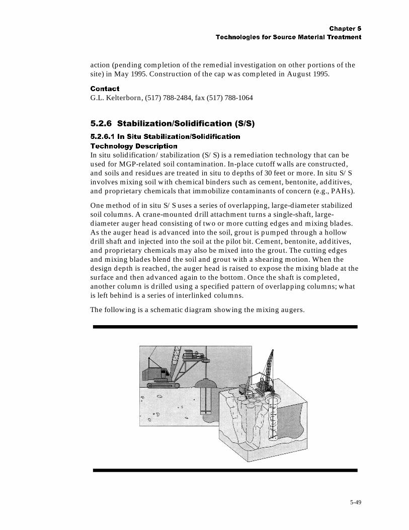
&KDSWHU �
7HFKQRORJLHV IRU 6RXUFH 0DWHULDO 7UHDWPHQW
5-49
action (pending completion of the remedial investigation on other portions of thesite) in May 1995. Construction of the cap was completed in August 1995.
&RQWDFW
G.L. Kelterborn, (517) 788-2484, fax (517) 788-1064
����%�����&�'����"�����������(�"�)
������� ,Q 6LWX 6WDELOL]DWLRQ�6ROLGLILFDWLRQ
7HFKQRORJ\ 'HVFULSWLRQ
In situ solidification/stabilization (S/S) is a remediation technology that can beused for MGP-related soil contamination. In-place cutoff walls are constructed,and soils and residues are treated in situ to depths of 30 feet or more. In situ S/Sinvolves mixing soil with chemical binders such as cement, bentonite, additives,and proprietary chemicals that immobilize contaminants of concern (e.g., PAHs).
One method of in situ S/S uses a series of overlapping, large-diameter stabilizedsoil columns. A crane-mounted drill attachment turns a single-shaft, large-diameter auger head consisting of two or more cutting edges and mixing blades.As the auger head is advanced into the soil, grout is pumped through a hollowdrill shaft and injected into the soil at the pilot bit. Cement, bentonite, additives,and proprietary chemicals may also be mixed into the grout. The cutting edgesand mixing blades blend the soil and grout with a shearing motion. When thedesign depth is reached, the auger head is raised to expose the mixing blade at thesurface and then advanced again to the bottom. Once the shaft is completed,another column is drilled using a specified pattern of overlapping columns; whatis left behind is a series of interlinked columns.
The following is a schematic diagram showing the mixing augers.

&KDSWHU �
7HFKQRORJLHV IRU 6RXUFH 0DWHULDO 7UHDWPHQW
5-50
A second method of in situ S/S requires the MGP wastes to be stabilized inshallow soil (approximately the upper 2 feet). In this scenario, admixturescontaining Portland cement, bentonite, and other chemicals are placed directly onthe ground surface. Tillers and sheepsfoot rollers are used to mix and compact thesoil.
2SHUDWLRQDO &RQVLGHUDWLRQV
The success of S/S methods depends on soil type and properties, contaminanttype and concentrations, moisture content, organic content, density, permeability,unconfined compressive strength, leachability, pH, and particle size. A treatabilitystudy is recommended for this technology to create a mix that minimizes leachingand has appropriate strength characteristics. The creation of concrete-like materialin the subsurface may severely limit access to utilities, which may need to bepermanently rerouted. The machinery used for in situ S/S via mixing augers isapproximately the same size as a large drilling rig; low overhead lines may limitthe use of this technology.
$SSOLFDWLRQV DQG &RVW
Inorganic constituents have traditionally been the target contaminant group for insitu S/S. The technology has limited effectiveness against SVOCs and no expectedeffectiveness against VOCs. It has been applied to MGP sites for PAH treatment.Costs for cement-based S/S techniques vary widely according to materials orreagents used and their availability, project size, and the chemical nature of thecontaminants. In situ mixing/auger techniques average $40 to $60 per cubic yardin shallow applications.
%HQHILWV
� Immobilizes contaminants
� Neutralizes soil
� Improves bearing capacity or shear strength of treated area
� Leaves treated area, if reinforced, able to withstand differential soil andhydrostatic loading
/LPLWDWLRQV
� Possible leaching of volatile or mobile constituents
� Creation of concrete-like material in the subsurface (may severely limit accessto utilities, which may need to be permanently rerouted)
� Possible significant increase in volume of mixture (up to double the originalvolume)
� Reagent delivery and effective mixing more difficult than in ex situapplications
&DVH 6WXGLHV
&ROXPEXV� *HRUJLD� )RUPHU 0*3 6LWH
A full-scale demonstration of in situ S/S for MGP contamination was performed inColumbus, Georgia, where an estimated 94,000 cubic yards of soil at a town gas

&KDSWHU �
7HFKQRORJLHV IRU 6RXUFH 0DWHULDO 7UHDWPHQW
5-51
site were stabilized (Geo-Con, 1993). The 4-acre site is located in the centralbusiness district of Columbus and is bounded to the west by the ChattahoocheeRiver. Contaminated soils extended over a 15-foot interval beneath 10 to 20 feet ofmiscellaneous fill. Depth to groundwater was approximately 20 feet bgs, and the10-foot saturated zone was underlain by bedrock.
In situ treatment was accomplished by mixing/drilling a Type I Portland Cementslurry with the soil to an approximate depth of 35 feet using an 8-foot-diameterauger. A containment wall was installed adjacent to the river; the remainder of thesite was stabilized by advancing augers at approximately 1,800 overlappinglocations.
Prior to treatment, contamination of the MGP-affected soils was as high as 300mg/kg of VOCs, 2,400 mg/kg of PAHs, and 5,500 mg/kg of petroleumhydrocarbons. The performance criteria for the concrete mixtures were:
� Ultimate Compressive Strength (UCS) of 60 psi within 28 days
� Permeability of no more than 1x10 -6 cm/s for the containment wall and nomore than 1x10 -5cm/s for the remainder of the site
� PAH concentration in TCLP leachate not to exceed 10 mg/L
UCS testing was conducted on all samples, and permeability and leach testing wasperformed on 10 percent of the samples obtained from approximately 300randomly selected shafts of freshly stabilized soils. Any shafts that did not complywith the performance criteria had to be reprocessed. After the soils were stabilized,the area was covered with an HDPE liner and backfilled soil and then convertedinto a park and walkway.
&RQWDFWV
Darahyl Dennis, Georgia Power Company, Atlanta, GA 30302, (404) 526-7064Harold F. Reheis, Georgia Department of Natural Resources, Atlanta, GA 30334,(404) 656-4713
0DQLWRZRF� :LVFRQVLQ� )RUPHU 0*3 6LWH
The Wisconsin Fuel & Light site is a former MGP facility located along theManitowoc River in Manitowoc, Wisconsin. The site had been filled withuncontrolled material, including debris and other material typically used behindsea walls. Portions of the foundations from the previous coal gasificationstructures also remained. The underlying soils at this site were contaminated withcoal tars; these were stabilized using a reagent mixture of activated carbon,cement, fly ash, and organophilic clays.
The S/S treatment of impacted soil was accomplished by simultaneous injectionand mixing of cement-based grout using 4- and 7-foot-diameter tools. This createda series of overlapping, vertically oriented columns of stabilized soil. The rotaryand vertical movement of the boring/mixing tool was designed to assure effectivemixing. In 1994 alone, a total volume of 6,859 cubic yards of soil was stabilized

&KDSWHU �
7HFKQRORJLHV IRU 6RXUFH 0DWHULDO 7UHDWPHQW
5-52
with 209 soil columns. Overall, approximately 15,000 cubic yards of soil weretreated during a 2-year period to an average depth of 32 feet.
A minimum UCS of 120 psi and a permeability of 1.8 x 10 -7 cm/s were achievedthrough the stabilization process, and the stabilized material also passed ASTMD559 and D560 durability tests. Verification soil samples were extracted using amodified Static Leaching Method. Of 16 extracts, only one contained a PAH(naphthalene at a concentration of 16 µg/L), and no other SVOCs were detectedabove the Minimum Detection Limit. Four extracts contained a VOC, methylenechloride, but because this compound also showed up in an apparatus blank and isnot a normal constituent of coal tar, it is thought that this was a laboratorycontaminant.
&RQWDFW
Ted Vallis, Wisconsin Fuel & Light, Manitowoc, Wisconsin, (414) 683-2538
������� ([ 6LWX 6WDELOL]DWLRQ�6ROLGLILFDWLRQ �6�6�
7HFKQRORJ\ 'HVFULSWLRQ
Stabilization/solidification (S/S) uses physical and chemical means to reduce themobility of hazardous substances and contaminants. Unlike other remedialtechnologies, S/S seeks to trap or immobilize contaminants, instead of removingthem. The term S/S has been used synonymously with other terms, includingimmobilization, encapsulation, and fixation (GRI, 1996). Specific definitions havebeen assigned to each of these terms by USEPA and others to differentiate amongthem. For the purposes of this document, all of these technologies will be referredto as S/S.
Ex situ S/S was originally developed for inorganic wastes. Although thistechnology has limited applicability to organics and cyanides, it may be useful atMGP sites for management of purifier box wastes, gas-holder tank sludge, andsoils contaminated with organic compounds (GRI, 1996). Contaminants arephysically bound or enclosed within a stabilized mass (solidification), or chemicalreactions are introduced between the stabilizing agent and contaminants to reducetheir mobility (stabilization).
Ex situ S/S is one method by which soil containing MGP wastes can be stabilizedand replaced. The technology typically involves mixing the soil with chemicalbinders that solidify and/or immobilize the chemicals of concern. Pugmills areoften used to perform mixing, although stockpiles may be mixed by mechanicalmeans. Following S/S, treated materials may be replaced in their excavation,recompacted, and allowed to cure. Leachability testing is typically performed toverify contaminant immobilization.
There are many variations of the S/S technology using different processes and/orstabilizing agents such as Pozzolan/Portland cement, bitumen, and emulsifiedasphalt. The technology has been applied to soils, sludges, lagoons, andradioactive waste. The use of MGP soils in the production of asphalt is discussed

&KDSWHU �
7HFKQRORJLHV IRU 6RXUFH 0DWHULDO 7UHDWPHQW
5-53
in Section 5.2.3. The discussion in this section will focus on the use ofPozzolan/Portland Cement with MGP soils.
Pozzolan/Portland cement consists primarily of silicates from Pozzolanic-basedmaterials like fly ash, kiln dust, pumice, or blast furnace slag as well as cement-based materials. These materials react chemically with water to form a solid matrixthat improves the strength of the matrix in which waste is found and minimizesthe likelihood of contaminant leaching. They also raise the pH of the water, whichmay help precipitate and immobilize some heavy metals. Pozzolanic and cement-based binding agents are typically appropriate for inorganic contaminants. Theeffectiveness of this binding agent with organic contaminants varies (USEPA,1998).
2SHUDWLRQDO &RQVLGHUDWLRQV
A key design consideration is the identification of a stabilizing agent that iscompatible with the waste at a site and that yields a treated product that containsno free liquids, meets a minimum compressive strength, and does not leachcontaminants (GRI, 1996). Lab- and pilot-scale studies are required to identify thetype and quantity of agent for each application. Physical and chemicalcharacterization of the soil are also required to select suitable mixing materials.
The effectiveness of ex situ S/S depends primarily on effective mixing. If largematerials (greater than 3/8 inch) are present, they must be excluded by screening.These materials can be used in the S/S process if they are crushed and screened.Mixing time should be sufficient to produce a homogeneous mix. This parameterhas a great impact on project duration and treatment cost (GRI, 1996).
Soil parameters that must be determined for ex situ S/S include particle size,Atterberg limits, moisture content, metal concentrations, sulfate content, organiccontent, and density. Post-treatment parameters that require monitoring andtesting include permeability, unconfined compressive strength, leachability,microstructure analysis, and physical and chemical durability (USEPA, 1998). Soilparticle size is an important factor as fine particles may delay setting and curingtimes and can surround larger particles, causing weakened bonds in S/S processes(USEPA, 1998). Soil homogeneity and isotropy also affect S/S. Larger particles,such as coarse gravel or cobbles, may not be suitable for the S/S technology.
A consideration in the use of the technology at MGP sites is the presence of oil andgrease. Oil and grease coat soil particles, which tends to weaken the bond betweensoil and cement in cement-based solidification (USEPA, 1998).
$SSOLFDWLRQV DQG &RVW
Ex situ S/S may be used to treat soils from MGP sites. It is a viable option whensoil contaminants are primarily metals (as with purifier box wastes). Full-scale S/Sof free-phase hydrocarbons and contaminated soils from MGP sites has beenperformed, but there is little documentation of the result of these demonstrations(GRI, 1996).
Cost of ex situ S/S depends on the costs of mobilization/demobilization ofpersonnel and equipment, excavation, equipment, startup, supplies and

&KDSWHU �
7HFKQRORJLHV IRU 6RXUFH 0DWHULDO 7UHDWPHQW
5-54
consumables, labor, utilities, and analytical requirements. Ex situ S/S processesare among the most accepted remediation technologies. Comparing representativeoverall costs from more than a dozen vendors gives an approximate cost of under$110 per metric ton ($100 per ton), including excavation (USEPA, 1998).
%HQHILWV
� Has been widely used to immobilize inorganic chemicals; several vendorsclaim that their proprietary additives can make organics amenable tostabilization
/LPLWDWLRQV
� Performance of S/S process is dependent upon the chemical composition of thewastes
� Long-term immobilization of contaminants possibly affected by environmentalconditions
� Certain wastes incompatible with certain S/S processes; treatability studiesgenerally required
� VOCs are generally not immobilized by the stabilization process
� Long-term effectiveness not demonstrated for many contaminant/processcombinations
� Volumetric increase in amount of material
&DVH 6WXG\
'X4XRLQ )RUPHU 0*3 6LWH
Remedial activities were conducted under the Illinois Site Remediation Program atan 8-acre former MGP site owned by Ameren CIPS in DuQuoin, Illinois. Theremedial work, funded jointly by Ameren CIPS, Commonwealth Edison, andNicor Gas, was conducted during the first half of 1997.
Tar and purifier waste was excavated from a lagoon approximately 59,650 squarefeet in area. A total of 4,290 tons of tar and tar-contaminated soil was generatedduring the excavation of impacted material at the site. This material wasmanifested as a hazardous waste and transported to a RCRA Subtitle C landfill.
The area identified as the lagoon excavation was stabilized by incorporatingcalciment bottom ash at a ratio of 7 parts ash to 10 parts soil into the bottom twofeet of impacted clay subgrade. The stabilized clay was then placed back in 6-inchlifts and compacted with a D-6 bulldozer and sheepsfoot roller.
Soils from other areas of the site, identified as posing a risk greater that 10 -6 toindustrial workers (hot-spot soils), were excavated, stabilized with calcimentbottom ash (at a one-to-ten ratio) and placed on top of the lagoon subgrade. Thematerial was placed in 6-inch lifts and compacted with the use of the D-6bulldozer and sheepsfoot roller. Approximately 4,611 cubic yards of stabilizedmaterial were used as backfill in the lagoon area. Confirmation sampling

&KDSWHU �
7HFKQRORJLHV IRU 6RXUFH 0DWHULDO 7UHDWPHQW
5-55
performed in the area of excavation and stabilization activities indicated that theremediation activities were successful.
Backfill obtained from an offsite commercial source was used to cover thestabilized material in the lagoon area. The backfill was compacted in place, gradedto promote drainage of precipitation, and seeded with prairie grass.
The site is zoned commercial/industrial and will be used for these purposes in thefuture. Because stabilized impacted soils are present beneath the 1-foot surfacecover, certain procedures and precautions will be followed to maintain this layer.
&RQWDFWV
Don Richardson, Ameren CIPS, (314) 554-4867Peter McCauley, Com Ed, (312) 394-4470Stan Komperta, Illinois Environmental Protection Agency, (217) 782-5504
����*������+����
7HFKQRORJ\ 'HVFULSWLRQ
Soil washing is a physical/chemical process for scrubbing soils ex situ to removecontaminants.
The process removes contaminants from soils in one of two ways (USEPA, 1998):by dissolving or suspending them in the wash solution (which can be sustained bychemical manipulation of pH for a period of time); or by concentrating them into asmaller volume of soil through particle size separation, gravity separation, andattrition scrubbing (similar to techniques used in sand and gravel operations).
Soil washing is considered a media transfer technology because contamination isnot destroyed but merely transferred from solid- to liquid-phase media. Thecontaminated water generated from soil washing is treated with the technologiessuitable for the contaminants. Soil washing is potentially applicable to soilscontaminated with a wide variety of heavy metals, radionuclides, and organiccontaminants. Application of the process is not widespread in the United States.This technology has been more widely applied in Europe.
The concept of reducing soil contamination through the use of particle sizeseparation is based on the finding that most organic and inorganic contaminantstend to bind, either chemically or physically, to clay, silt, and organic soil particles(USEPA, 1998). Silt and clay attach to sand and gravel particles by physicalprocesses, primarily compaction and adhesion. Washing separates the fine (small)clay and silt particles from coarser sand and gravel soil particles thusconcentrating contaminants into a smaller volume of soil that can then bemanaged (treated further or disposed of at a landfill). Gravity separation iseffective for removing high- or low-specific-gravity particles such as heavy-metal-containing compounds. Attrition scrubbing removes adherent contaminant filmsfrom coarser particles. It can also increase the fines in soils. The clean soil can bereturned to the site for reuse.

&KDSWHU �
7HFKQRORJLHV IRU 6RXUFH 0DWHULDO 7UHDWPHQW
5-56
Complex mixtures of contaminants in soil (such as a mixture of metals, nonvolatileorganics, and semivolatile organic compounds) and heterogeneous contaminantcompositions throughout a soil mixture make it difficult to formulate a singlewashing solution that will consistently and reliably remove the different types ofcontaminants. Soil washing is typically not recommended for these types of sites.
2SHUDWLRQDO &RQVLGHUDWLRQV
Soil type is an important factor for soil washing. In general, coarse, unconsolidatedmaterials, such as sands and fine gravels, are easiest to treat. Soil washing may notbe effective where the soil is composed of large percentages of silt and claybecause of the difficulty of separating the adsorbed contaminants from fineparticles and from wash fluids (USEPA, 1998).
High soil moisture content may cause excavation, material handling, and materialtransport problems (USEPA, 1998).
The pH of the waste being treated may affect soil washing; high pH in soilnormally lowers the mobility of inorganics in soil (USEPA, 1998).
High humic content will bind the soil, decreasing the mobility of organics andthus the threat to groundwater; however, high humic content can inhibit soilwashing as a result of strong adsorption of the contaminant by the organicmaterial (USEPA, 1998).
A complete bench-scale treatability study is typically required before using soilwashing as a remedial solution. Like any ex situ soil treatment, this technologyrequires space for soil processing and materials handling.
$SSOLFDWLRQV DQG &RVW
This technology is suitable for treating soils and sediment contaminated withorganics such as PCBs, creosote, fuel residues, and heavy petroleum; heavy metalssucah as cadmium, chromium, lead, arsenic, copper, cyanides, mercury, nickel,and zinc; and radionuclides. The technology can recover metals and can clean awide range of organic and inorganic contaminants from coarse-grained soils.
At the present time, soil washing is used extensively in Europe but has had limiteduse in the United States. Between 1986 and 1989, the technology was one of theselected source control remedies at eight Superfund sites. The average cost for useof this technology, including excavation, is approximately $170 per ton, dependingon site-specific conditions and the target waste quantity and concentration.
%HQHILWV
� Offered by multiple vendors
�� High degree of certainty regarding treatment performance
/LPLWDWLRQV
� Material handling possibly expensive and time consuming, especially for largeamounts

&KDSWHU �
7HFKQRORJLHV IRU 6RXUFH 0DWHULDO 7UHDWPHQW
5-57
� Applicability and effectiveness of the process limited by:
- Complex waste mixtures (e.g., metals with organics) which make formulating washing fluid difficult
- High humic content in soil, which may require pretreatment
� Washwater requiring treatment at demobilization
� Additional treatment steps that may be required to address hazardous levels ofwashing solvent remaining in the treated residuals
� Difficultly removing organics adsorbed onto clay-size particles
&DVH 6WXGLHV
)RUPHU %DVIRUG *DVZRUNV� 1RWWLQJKDP� 8.
A large-scale UK soil washing project is being conducted at the former Basfordgasworks site in Nottingham. The 7.8-hectare (ha) site is owned by BG plc, the UKgas supply infrastructure group. The cleanup is valued at $7.5 million (Haznews,1998).
Soil washing commenced in August 1997, and was scheduled to be completed inJuly 1998 after processing approximately 72,000 cubic meters of contaminatedmaterial. The soil washing was performed by Linatex/Heijmans, a joint-venturebetween UK and Dutch firms, using a plant with a nominal process rate of 50tonnes per hour.
The Basford site is underlain by a drinking water aquifer, with no subsurfacegeological barrier to prevent off-site migration of contaminants. The soilconditions at the site made it a suitable candidate for evaluating the cost-effectiveness of soil washing; information which would be useful in evaluatingthis technology for other contaminated MGP sites. Basford began operating in1854 and was the principal gas supply for the City of Nottingham. The site alsoprovided by-products such as coke, sulphuric acid, and ammonium sulphatefertilizer until gas production stopped in 1972 (Haznews, 1998).
During the site characterization, 350 test pits were dug on a 10 meter grid,producing 2,500 samples for analytical testing. This detailed investigation alloweda more accurate identification of waste types, volume, and location. A model wassubsequently developed to optimize the treatment technology and estimate theamount of materials that could be recycled. For example, 26,000 cubic meters ofclean ash and clinker are being recovered for use in steel and building blockproduction (Haznews, 1998).
Approximately 91,000 cubic meters of contaminated material was identified. Ofthis, about 15,000 cubic meters has been classified as untreatable (along with tarand asbestos wastes) and was sent to an off-site disposal location. The remainderof the wastes are being processed through the soil washing plant.
In the soil washing process, excavated material is crushed and screened to 100 mmand magnetically separated. The remaining material is wetted and then passed to

&KDSWHU �
7HFKQRORJLHV IRU 6RXUFH 0DWHULDO 7UHDWPHQW
5-58
a 2-mm vibrating screen where it is disaggregated with high-pressure water. The >2 mm gravel fraction goes to a counter-current washer and is eventually drainedand discharged for reuse as onsite fill. The gravel washwater and a smaller slurryfraction is split between two hydrocyclones which separates the material into a 63µm to 2 mm sand fraction and a < 63 µm slurry (Haznews, 1998). The sand isprocessed in a dense medium separator from which clean sand is dewatered andthen discharged to a collection bay. The fines fraction slurry is treated in athickener tank where flocculants may be added to improve the treatment process.This tank produces sludge with 20 to 40 percent dry matter which is pumped to acontinuous filter press. The resulting contaminated filter cake is sent to a landfillfor disposal.
Light materials, such as coke, wood fragments, and plastics, are separated outduring the washing process and also sent to the landfill with the contaminatedfines (Haznews, 1998).
According to BG’s property division, the use of soil washing has resulted in aremediation period that is 60 to 70 percent longer than the conventional clean-upapproach of excavation of contaminated material and landfill disposal. Howeverthe advantages of soil washing include the reduced need for imported clean fill,and a large reduction in transportation during the site work. Overall, the cost ofthe project is comparable to a “dig and haul” approach (Haznews, 1998).
6,7( 3URJUDP 'HPRQVWUDWLRQ� 7RURQWR� 2QWDULR
Soil washing was accepted into the Superfund Innovative Technology Evaluation(SITE) Demonstration Program in the winter of 1991. It was demonstrated inToronto, Ontario, Canada, in April 1992 as part of the Toronto HarbourCommission soil recycling process.
The soil washing process begins when an attrition soil wash plant removesrelatively uncontaminated coarse soil fractions using mineral processingequipment; contaminants are concentrated in a fine slurry that is routed for furthertreatment. The wash process includes a trommel washer to remove clean gravel,hydrocyclones to separate the contaminated fines, an attrition scrubber to freefines from sand particles, and a density separator to remove coal and peat from thesand fraction. If only inorganic contaminants are present, the slurry is treated in aninorganic chelator unit. This process uses an acid leach to free inorganiccontaminant from the fine slurry and then removes the metal using solidchelating-agent pellets in a patented countercurrent contactor. The metals arerecovered by electrowinning from the chelation agent regenerating liquid. Organicremoval is accomplished by first chemically pretreating the slurry from the washplant or metal removal process. Next, biological treatment is applied in upflowslurry reactors using bacteria that have developed naturally in the soils. Thetreated soil is dewatered using hydrocyclones and returned to the site from whichit was excavated.
The technology is designed to reduce organic and inorganic contaminants in soils.The process train approach is most useful when sites have been contaminated as a

&KDSWHU �
7HFKQRORJLHV IRU 6RXUFH 0DWHULDO 7UHDWPHQW
5-59
result of multiple uses over a period of time. Typical sites where the process trainmight be used include refinery and petroleum storage facilities, former metalprocessing and metal recycling sites, and manufactured gas and coal or cokeprocessing and storage sites. The process is less suited to soils with high inorganicconstituents that are inherent to the mineralogy.
Results of the demonstration described above have been published in theDemonstration Bulletin (EPA/520/MR-92/015), the Applications Analysis Report(EPA/540/AR-93/517), the Technology Evaluation Report (EPA/540/R-93/517),and the Technology Demonstration Summary (EPA/540/SR-93/517). Thesereports are available from USEPA.
The demonstration results showed that soil washing produced clean coarse soilfractions and concentrated the contaminants in the fine slurry. The chemicaltreatment process and biological slurry reactors, when operated on a batch basiswith a nominal 35-day retention time, achieved at least a 90 percent reduction insimple PAH compounds such as naphthalene, but did not meet the approximately75 percent reduction in benzo(a)pyrene required to achieve the cleanup criteria.
The biological process discharge did not meet the cleanup criteria for oil andgrease; the washing process removed almost no oil and grease. The hydrocyclonedewatering device did not achieve significant dewatering. Final process slurrieswere returned to the excavation site in liquid form.
The metals removal process achieved a removal efficiency of approximately 70percent for toxic heavy metals such as copper, lead, mercury, and nickel.
The metals removal process equipment and chelating agent were fouled by free oiland grease, forcing sampling to end prematurely. Biological treatment or physicalseparation of oil and grease will be required to avoid such fouling.
&RQWDFW
Teri Richardson, USEPA Project Manager, National Risk Management ResearchLaboratory, 26 West Martin Luther King Drive, Cincinnati, OH 45268, (513) 569-7949, fax (513) 569-7105
6,7( 3URJUDP 'HPRQVWUDWLRQ� 6DJLQDZ� 0LFKLJDQ
A field demonstration of Bergmann, Inc.’s soil washing technology was conductedin May 1992 at the Saginaw Bay Confined Disposal Facility in Saginaw, Michigan.The Applications Analysis Report (EPA/540/AR-92/075) and the DemonstrationBulletin (EPA/540/MR-92/075) are available from USEPA.
Demonstration results indicate that the soil- and sediment-washing system caneffectively isolate and concentrate PCB contamination into organic fractions andfines. Levels of metals contamination were also beneficially altered. Theeffectiveness of soil and sediment washing on inorganic compounds equaled orexceeded its performance for PCB contamination.

&KDSWHU �
7HFKQRORJLHV IRU 6RXUFH 0DWHULDO 7UHDWPHQW
5-60
During a 5-day test in May 1992, the Bergmann soil and sediment washing systemexperienced no downtime, operating for 8 hours per day to treat dredgedsediments from the Saginaw River.
The demonstration provided the following results:
� Approximately 71 percent of the particles smaller than 45 µm in the inputsediment were apportioned to the enriched fines stream.
� Fewer than 20 percent of the particles smaller than 45 µm in the input sedimentwere apportioned to the coarse clean fraction of soil.
The distributions of the concentrations of PCBs in the input and output streamswere as follows:
� Input sediment = 1.6 mg/kg
� Output coarse clean fraction = 0.20 mg/kg
� Output humic materials = 11 mg/kg
� Output enriched fines = 4.4 mg/kg
Heavy metals were concentrated in the same manner as the PCBs. The coarse cleansand consisted of approximately 82 percent of the input sediment.
&RQWDFWV
Mr. Jack Hubbard, USEPA Project Manager, National Risk Management ResearchLaboratory, 26 West Martin Luther King Drive, Cincinnati, OH 45268, (513) 569-7507, fax (513) 569-7620Mr. George Jones, Bergmann, A Division of Linatex, Inc., 1550 Airport Road,Gallatin, TN, 37066-3739, (615) 230-2217, fax (615) 452-5525
6,7( 3URJUDP 'HPRQVWUDWLRQ� 1HZ %ULJKWRQ� 0LQQHVRWD
The BioTrol Soil Washing System is a patented, water-based volume reductionprocess used to treat excavated soil. The system may be applied to contaminantsconcentrated in the fine-sized soil fraction (silt, clay, and soil organic matter) or inthe coarse soil fraction (sand and gravel).
In the first part of the process, debris is removed from the soil. The soil is thenmixed with water and subjected to various unit operations common to the mineralprocessing industry. The equipment used in these operations can include mixingtrommels, pugmills, vibrating screens, froth flotation cells, attrition scrubbingmachines, hydrocyclones, screw classifiers, and various dewatering apparatus.
The core of the process is a multistage, countercurrent, intensive scrubbing circuitwith interstage classification. The scrubbing action disintegrates soil aggregates,freeing contaminated fine particles from coarser material. In addition, surficialcontamination is removed from the coarse fraction by the abrasive scouring actionof the particles themselves. Contaminants may also be solubilized as dictated bysolubility characteristics or partition coefficients.

&KDSWHU �
7HFKQRORJLHV IRU 6RXUFH 0DWHULDO 7UHDWPHQW
5-61
Contaminated residual products can be treated by other methods. Process water isnormally recycled after biological or physical treatment. Contaminated fines maybe disposed of offsite, incinerated, stabilized, or biologically treated.
This system was developed initially to clean soils contaminated with woodpreservative wastes, such as PAHs and PCP. The system may also apply to soilscontaminated with petroleum hydrocarbons, pesticides, PCBs, various industrialchemicals, and metals.
The BioTrol Soil Washing System was accepted into the SITE DemonstrationProgram in 1989 and demonstrated between September and October 1989 at theMacGillis and Gibbs Superfund site in New Brighton, Minnesota. A pilot unit witha treatment capacity of 500 pounds per hour operated 24 hours per day during thedemonstration. Feed for the first phase of the demonstration (2 days) consisted ofsoil contaminated with 130 ppm PCP and 247 ppm total PAHs; feed for the secondphase (7 days) consisted of soil containing 680 ppm PCP and 404 ppm total PAHs.Contaminated process water was treated biologically in a fixed-film reactor andthen recycled. A portion of the contaminated soil fines was treated biologically in athree-stage, pilot-scale EIMCO Biolift reactor system supplied by the EIMCOProcess Equipment Company. The Applications Analysis Report (EPA/540/AR-91/003) and the Technology Evaluation Report Volume I (EPA/540/5-91/003a)and Volume II (EPA/540/5-91/003b and EPA/540/5-91/003c) are available fromEPA.
Key findings from the BioTrol demonstration are summarized below:
� Feed soil (dry weight basis) was successfully separated into 83 percent washedsoil, 10 percent woody residues, and 7 percent fines. The washed soil retainedabout 10 percent of the feed soil contamination; 90 percent of thiscontamination was contained in the woody residues, fines, and process wastes.
� The multistage scrubbing circuit removed up to 89 percent PCP and 88 percenttotal PAHs, based on the difference between concentration levels in thecontaminated (wet) feed soil and the washed soil.
� The scrubbing circuit degraded up to 94 percent PCP in process water. PAHremoval could not be determined because of low influent concentrations.
&RQWDFW
Dennis Chilcote, BioTrol, 10300 Valley View Road, Suite 107, Eden Prairie, MN55344-3456, (612) 942-8032, fax (612) 942-8526
����,������-� � �$.� ������(�-$)
SVE is mechanically similar to bioventing (Section 5.2.4.2), but is operated at ahigher flow rate to achieve volatile compound removal in addition to oxygenreplenishment. SVE uses an electric- or gasoline-powered blower systemconnected to wells via manifolds. Air treatment, whether through a separatesystem (such as activated carbon or catalytic oxidation) or as part of a gasoline-

&KDSWHU �
7HFKQRORJLHV IRU 6RXUFH 0DWHULDO 7UHDWPHQW
5-62
powered system, is usually the most expensive single component of an SVE projectand may represent as much as 50 percent of the overall cost.
Performance of an SVE system is monitored using measurements at the blowersystem and at piezometers (small-diameter wells or soil gas sample points)installed in the zone being treated. Flow measurements at the blower or atindividual wells can be used to help calculate removal rates. Vapor samples frompiezometers, wells, or at the blower discharge can be analyzed in the field or by alaboratory, and the results can be used to estimate the rate of subsurfacedecontamination and the rate of volatile compound removal. Vapor samples fromthe discharge of the air treatment system are usually required to test systemperformance and to verify permit requirements. Final evaluation of SVEperformance can be assessed by collecting soil vapor samples from piezometersand/or soil samples from the treated zone.
2SHUDWLRQDO &RQVLGHUDWLRQV
The suitability of SVE for MGP sites will depend on the site-specific requirementsfor volatile compound removal or prevention of volatile compound migration as aremediation objective. The site also needs to have a water table depth at least 10feet and a subsurface profile that allows air to flow through the zone to be treated.This profile criterion is met if the soil is coarse- or fine-grained but not saturatedand if the organic compound mass is infiltrated into the soil, rather than collectedin a subsurface pool (which would be impermeable to air flow).
The design feasibility of SVE is typically proven through a field pilot test. The testtypically consists of pumping a single well that is screened in the center of thezone to be treated. Piezometers are placed throughout and near the margins of thezone to be treated. The purposes of this test are to:
� Size the blower by assessing how much air can be pumped from a well.
� Size the air treatment system by determining what initial concentrations might be expected.
� Observe the subsurface flow pattern throughout the zone of treatment.
If the piezometers indicate the pilot test well did not produce an adequatesubsurface flow pattern, the full-scale design could call for additional wells, a newwell with a deeper screened interval, or sealing to eliminate surface leakage.Shallow sites may be more effectively treated using horizontal wells in trenches.
Most SVE systems operate for 1 to 3 years. During this time, the air treatmentsystem requires periodic maintenance or changeout, a condensate tank requiresemptying (especially in cold weather), and samples and measurements need to becollected and reported. At the site, the aboveground portion of the system usuallytakes up one or two parking spaces and almost always requires 115V or 220Velectrical power. Natural gas is sometimes required (if catalytic oxidation isselected as the air treatment option). The blower itself may be a source of excessivenoise if silencers (upstream and downstream) or soundproof containment are notprovided or if the blower is undersized and working near its maximum output.The underground portion of the system is typically accessed through well vaults,
&KDSWHU �
7HFKQRORJLHV IRU 6RXUFH 0DWHULDO 7UHDWPHQW
5-63
and the manifold lines connecting the wells to the blower system are often buriedin frequently accessed areas.
Sites with relatively shallow water tables or with wells screened near the watertable can experience excessive water accumulation and blockage of air flow if toomuch vacuum is applied to the system. Most systems can be operated safely underthese conditions by managing the applied vacuum (in feet of water column) to beless than one half the distance from the water table to the top of the well screen.
Granular activated carbon is often selected as the air treatment alternative becauseof its minimal power requirements, its availability, and its acceptability toregulators. It is often the least expensive, on a unit basis, for sites with relativelylow vapor concentrations. Carbon operates at highest efficiency whentemperatures are lower than 120(F; however, most SVE design manuals fail toprovide guidance on temperature management of the blower discharge to thecarbon vessels. Excessive heat may be a concern at sites with high ambienttemperature, such as in the south or southwestern United States, and/or whererelatively high vacuums are required because of fine-grained soil conditions. Inthese situations, carbon may still be cost effective if used in conjunction with acondenser or a heat exchanger.
$SSOLFDWLRQV DQG &RVW
SVE has been used as a remediation process of choice at thousands ofunderground storage tank leak sites. Applications at MGP sites are not aswidespread; however, SVE can be used to treat soils at sites contaminated withsome SVOCs (such as naphthalene).
SVE can be applied with little disturbance to existing facilities and operations. Thetechnology can be used at sites where areas of contamination are large and deep orwhen the contamination is present beneath a building. The system may bemodified depending on additional analytical and subsurface characterization dataand/or changing site conditions (RIMS, 1998).
The components of SVE systems are commonly available off the shelf, and thenecessary wells can be installed by any qualified local engineering firm.Aboveground installations typically include:
� Vacuum pumps and/or blowers and associated controls
� Pressure gauges and flow meters at wellheads and pumps
� Control valves to adjust air flow
� An air-liquid separator (for removing moisture from the extracted gases)
� Vapor treatment unit(s)
More complex SVE systems may incorporate trenches, horizontal wells, forced airinjection wells, passive air inlet wells, low permeability or impermeable surfaceseals, or multiple level vapor extraction wells in single boreholes. In addition,sophisticated systems are available to monitor moisture, contaminant levels, andtemperature (RIMS, 1998).

&KDSWHU �
7HFKQRORJLHV IRU 6RXUFH 0DWHULDO 7UHDWPHQW
5-64
The efficiency of SVE can be enhanced through the use of formation fracturing,pulsed pumping, or horizontal extraction wells. These enhancements can increasethe soil permeability or the efficiency of mass removal or allow access topreviously inaccessible areas of contaminated soil (e.g., below the water table, inless permeable formations) (RIMS, 1998).
Treatment costs for sites using SVE depend on various conditions such as site size,extent of contamination, regulatory requirements for permits, other site-specificand chemical-specific conditions, and site cleanup criteria. Therefore, cost can onlybe estimated on a case-by-case basis. To provide an indication of the range in SVEproject costs, the treatment of 185,000 cubic yards of soil at one site cost $2 percubic yard while, at another site where 650 cubic yards required treatment, thecost was $450 per cubic yard. These values represent treating the soil rather thancost per pound of contaminant treated. The major part of the total process costassociated with SVE is usually the operating expenses for labor, maintenance, andmonitoring (RIMS, 1998).
%HQHILWV
� Treats in situ, volatile compounds in soil, including areas beneath structures, atlower cost than excavation
� Accomplishes both volatile compound removal and oxygen replenishment,and promotes in situ biodegradation for compounds that may not be removed
� Can be implemented with relatively little disruption to ongoing operations
�� Focuses on volatile compounds, including benzene and naphthalene; thereforetreats the most mobile of the organic compounds beneath an MGP site, whichmakes it an effective risk-reduction approach
� Has well-established design and feasibility evaluations
/LPLWDWLRQV
� Not effective at sites where remediation goals include concentration reductionof low-volatility compounds (which are frequently important for MGP siterestoration)
� Difficult to successfully implement where the water table is shallower than 5 to10 feet below grade, or where the soil is fine-grained (clayey) and nearlysaturated
� Limited effectiveness on volatile compounds trapped in a liquid mass or poolof subsurface organic compounds (air will not flow through liquids; volatilecompounds trapped in liquids will only be removed through diffusion, whichis too slow to be cost effective)
&DVH 6WXG\
%HDOH $)%� 0DU\VYLOOH &DOLIRUQLD
Numerous SVE systems were installed using granular activated carbon with no airtemperature management. Upon start up, breakthrough of the carbon occurredwithin three days. Systems were retrofitted with a converted truck radiator

&KDSWHU �
7HFKQRORJLHV IRU 6RXUFH 0DWHULDO 7UHDWPHQW
5-65
installed downstream of the blower. Air was produced at ten degrees aboveambient for carbon treatment; and carbon efficiency increased three-fold (CH2M HILL, 1998; Nelline Scheuer).
&RQWDFWV
Ms. Carol Goudette, 9 CES/CEVR, 6601 “B” Street, Beale AFB, CA 95903Ms. Cori Condon, RWGCB, Assistant Engineering Geologist, 3443 Routies Road,Sacramento, CA 95827

&KDSWHU �
7HFKQRORJLHV IRU 6RXUFH 0DWHULDO 7UHDWPHQW
5-66

6-1
Chapter 6
����������
AFCEE, 1994. Bioventing Performance and Cost Summary, Draft. Brooks AFB, TX.
ASTM, 1995. Standard Guide for Risk-Based Corrective Action Applied atPetroleum Release Sites. Designation E-1739-95.
ASTM, 1996. Provisional Standard Guide for Accelerated Site Characterization forConfirmed or Suspected Petroleum Releases. Designation PS 3-95.
Alleman et al., 1995. “Bioventing PAH Contamination at the Reilly Tar Site.” InSitu Aeration: Air Sparging, Bioventing and Related Remediation Processes.Battelle Conference Proceeding.
Backhus, Debra A., Joseph N. Ryan, Daniel M. Groher, John K. MacFarlane, andPhilip M. Gschwerd, 1993. “Sampling Colloids and Colloid-AssociatedContaminants in Ground Water.” Ground Water, May-June, Vol. 31, No. 3, pp. 466-479.
Barnett Alexander, Catherine, 1977. MGP Site Planning: New CommunityDevelopment Opportunities. American Gas, November.
Barr Engineering Company, 1996. “Field Demonstrations of Thermal Desorptionof Manufactured Gas Plant Soils.” EPRI TR-105927. Electric Power ResearchInstitute. Minneapolis, Minnesota. September.
Bay Area Air Quality Management District, 1996. BAAQMD CEQA Guidelines,Assessing the Air Quality Impacts of Projects and Plans. p. 66. April.
Biotreatment News, 1996. “BAC Meets.” p. 10. November.
Bradley, L.J.N., B.H. Magee, and S.L. Allen, 1994. “Background Levels ofPolycyclic Aromatic Hydrocarbons (PAH) and Selected Metals in New EnglandUrban Soils.” Journal of Soil Contamination. CRC Press, Inc.
Bevolo, A.J., B.H. Kjartanson, and J.P. Wonder, 1996. “Ames Expedited SiteCharacterization Demonstration at the Former Manufactured Gas Plant Site,Marshalltown, Iowa.” Ames Laboratory. March.
Brown, S.M., D.R. Lincoln, and W.A. Wallace, 1988. “Application of ObservationalMethod to Hazardous Waste Engineering.” ASCE. Journal of ManagementEngineering, Vol. 6, No. 4, pp. 479-500.
Burton, Jacqueline C., 1994. “Expedited Site Characterization for RemedialInvestigations at Federal Facilities.” Argonne National Laboratory, FER III andWM II Conference & Exhibition. April 27-29.

&KDSWHU �
5HIHUHQFHV
6-2
Cambridge, Megan and Adam Palmer, 1998. “Expedited Remedial ActionProgram, Alhambra Manufactured Gas Plant Site.” Department of ToxicSubstances Control, California Environmental Protection Agency. April.
Chaconas, J. et al., 1997. “Bioremediation of Diesel-Contaminated Soils at NavyNational Test Site.” In-Situ and Onsite Bioremediation, Volume 1. Battelle Press, p.497.
Commonwealth of Pennsylvania, Department of Environmental Protection, 1996a.Multi-Site Remediation Agreements.
Commonwealth of Pennsylvania, Department of Environmental Protection, 1996b.“News Release: DEP Signs Innovative Environmental Agreement with UtilityCompanies.”
Covello, Vincent T. and Miley W. Merkhofer, 1993. Risk Assessment Methods:Approaches for Assessing Health and Environmental Risks. Plenum Press, New York,NY.
D’Appolonia, E, 1990. “Monitored Decisions.” Journal of Geotechnical Engineering,116:4-34.
Daddario, David J, 1997. “Revitalizing Real Estate Having ContaminationConstraints.” Proceedings from Conference on Risk-Based Decision-MakingInfluencing Financial Transactions and Brownfields Redevelopments, RTMCommunications, Inc., San Francisco, CA. November.
Department of Energy, Grand Junction Projects Office. Grand Junction, CO.
DíAngelo, Wm. Chip, and Anthony Chiesa, 1998. “Take it to the MART.” Soil &Groundwater Cleanup, June.
DMLSTM. http://www.margan.com.
Edwards, Nelson, T, 1983. “Polycyclic Aromatic Hydrocarbons (PAHs) in theTerrestrial Environment – A Review.” Journal of Environmental Quality, Vol. 12, No.4, p. 427. October-December.
Elsevier Sciences Inc, 1997. “Three Innovative Soil Gas Monitoring TechnologiesEvaluated.” The Hazardous Waste Consultant. Vol. 15, Issue 6, p. 1.8-1.10. (no authorcredited).
EPRI. Undated. Report Summary – Microscale Solvent Extraction Methods for theAnalysis of Solids and Liquids, Vol. 1 and 2. TR105317.
EPRI Journal, 1995. “In the Field.” May/June.

&KDSWHU �
5HIHUHQFHV
6-3
EPRI, 1997. Cold-Patch Asphalt. Report No. TR-108597.
EPRI, 1997. Review: Asphalt Batching of MGP Tar-Containing Soil. Report No. TR-108597. December.
Finley, et al., 1994. “Recommended Distribution For Exposure Factors FrequentlyUsed in Health Risk Assessment.” Risk Analysis, Vol. 14, No. 4.
Gas Research Institute (GRI), 1996. Management of Manufactured Gas Plant Sites,Volume 2.
Geo-Con, Inc, 1993. SSM Soil Stabilization, Case Study No. 2, Shallow Soil Mixingfrom Geo-Con, Inc.. C-SSM-02-93.
Haimann, Richard, Kathleen Schoen, Houshang Nezafati, and Jim Hartley, 1996.“An Observational Approach to Removing LNAPL.” Non-Aqueous Phase Liquids(NAPLs) in Subsurface Environment. Proceedings of the Conference of AmericanSociety of Civil Engineers. November 12-14.
Hasbrouck, J.C., O.A. Dickenson, T.T. Boyd, and W.P. Hasbrouck, 1996. BaselineSeismic Technology Report, 3D/3C Seismic for Site Characterization. U.S. Departmentof Energy. Grand Junction, CO. April.
Haznews, 1998. “Gasworks Clean-Up First Large-Scale Soil Washing in U.K.”Haznews, No. 122, p. 1. May.
Human and Ecological Risk Assessment, Vol. 4, No. 2, 1998. Special Issue:Probabilistic Methods in Risk Assessment. CRC Press. April.
Kelley, R.L., K. Kayser, V.J. Srivastava, et al, 1997. “MGP-REM Process in Full-Scale Landfarming Application: Integrating Low-Cost, Innovative Technologywith Risk-Based Cleanup.” Presented at the IGT Gas, Oil and EnvironmentalBiotechnology and Site Remediation Technologies, Orlando, Florida. December 8-10.
Leeson, A. and R.E. Hinchee, 1996. Battelle Memorial Institute. Principles andPractices of Bioventing. Volume 1: Bioventing Principles.
Nelson, G.L., Steven Shipley, Johanshir Golchin, Robert K. Kelly, Kevin Kayser,Vipul Srivastava and Don Richard. “Risk-Based Remediation of MGP WastesUsing an Innovative Process.”
Newmark, Robin L., and Roger D. Aines, 1998. “They All Like It Hot: FasterCleanup of Contaminated Soil and Groundwater.” Science & Technology Review.May.
New York State Department of Environmental Conservation, 1992. “News Release:For Release: Immediate, Tuesday, December 8, 1992, Niagra Mohawk to Act on 22Former Coal Gas Plants Statewide.”

&KDSWHU �
5HIHUHQFHV
6-4
Nielsen, P.H., T. Christensen, H. Albrechsten, and R. Gillham, 1996. “Performanceof the In-Situ Microcosm Technique for Measuring the Degradation of OrganicChemicals in Aquifers.” Ground Water Monitoring Review, Winter: 130-140.
NJDEP/PSE&G, 1996. Manufactured Gas Plant Site Remediation Streamlining Report.January.
North American Realty, 1997. CASE STUDY: Adaptive Reuse of Manufactured GasPlant Site to Mixed-Use Redevelopment. Racine, WI.
Onsite Environmental Laboratories Inc, 1998. (510) 490-8571/(617) 472-8022.http://www.onsitelabs.com.
Peck, R. B, 1969. “Advantages and Limitations of the Observational Method inApplied Soil Mechanics.” Geotechnique, Vol. 19, pp. 171-187.
PP&L, Resources, Inc, 1996. “News Release: PP&L to do Cleanup Work as Part ofLycoming College Redevelopment Project.”
PSE&G, 1997. Generic Remedial Investigation Work Plan. November.
Precision Sampling, Inc, 1998. Technical literature from company.
Rader, Kermit L., and Martin H. Sakolow, Jr, 1997. “Multi-Site RemediationAgreements.” Environmental Law, A Supplement to the Legal Intelligencer, PA LawWeekly. April.
RIMS, 1998. Online Remediation Technology Library. http://remedial.com.
Risk Analysis, Volume 14, Number 4, 1994. Special Issue: Uncertainty Analysis.Plenum Publishing Company. August.
Saar, R.A, 1997. “Filtration of Ground Water Samples: A Review of IndustryPractice.” Ground Water Monitoring and Remediation, Winter, Vol. XVII, No. 1, pp.56-62.
Solinst Canada Ltd, 1998. Technical literature from company. 1-800-661-2023.http://www.solinst.com
Srivastava, Vipul J, 1996. “MGP Site Remediation Strategies and a Review ofAvailable Technologies” and “IGT’s Innovative Approaches” from Proceedingsfrom the Ninth International IGT Symposium on Gas, Oil, and EnvironmentalBiotechnology. December 9-11.
TerraTherm, 1997. Cost and Performance Report. Provided to USEPA TechnologyInnovation Office & Tetra Tech EM, Inc. October 7.
The Annals of the American Academy of Political and Social Science, Vol. 545, 1996.Challenges in Risk Assessment and Risk Management. May.
Underhill, 1997. Battelle Bioremediation Conference Proceedings.
USACE, 1995. Engineering and Design Manual—Soil Vapor Extraction and Bioventing.Publication No. EM 1110-1-4001. November.

&KDSWHU �
5HIHUHQFHV
6-5
USACE, 1998. Engineering and Design Manual—Soil Vapor Extraction and Bioventing.Publication No. 1110-1-4001. November 30.
USEPA, 1989. Risk Assessment Guidance for Superfund, Volume 1, Human HealthEvaluation Manual (Part A).
USEPA, 1991. Applications Analysis Report. EPA/540/AR-91/003.
USEPA, 1991. Technology Evaluation Report. Volume 1. EPA/540/5-91/003a.
USEPA, 1991. Technology Evaluation Report, Volume 2. EPA/540/5-91/003b andEPA/540/5-91/003c.
USEPA, 1992. Applications Analysis Report. EPA/540/AR-92/075.
USEPA, 1992. Demonstration Bulletin. EPA/520/MR-92/015.
USEPA, 1993. Applications Analysis Report. EPA/540/AR-93/517.
USEPA, 1993. Technology Demonstration Summary. EPA/540/SR-93/517.
USEPA, 1993. Technology Evaluation Report. EPA/540/AR-93/517.
USEPA, 1997. Analysis of Selected Enhancements for Soil Vapor Extraction.EPA/542/R-97/007. September.
USEPA, 1997. Guiding Principles for Monte Carlo Analysis. Office of Research andDevelopment, NCEA. EPA/630/R-97/001.http://www.epa.gov/ncea/monteabs.htm.
USEPA, 1997. “Policy for Use of Probabilistic Analysis in Risk Assessment at theU.S. Environmental Protection Agency.” Office of the Administrator. Available athttp://www.epa.gov/ORD/spc/probcovr.htm andhttp://www.epa.gov/ORD/spc/probpol.htm.
USEPA, 1998a. Bangor Gas Works, Bangor, Maine. A Superfund RedevelopmentSuccess. Office of Emergency and Remedial Response. EPA/540/F-98/008. June.
USEPA, 1998. Region 9 Preliminary Remediation Goals (PRGs). May.
USEPA, 1998. Remediation Technologies Screening Matrix and Reference Guide.Downloaded from USEPA’s Technology Innovation Office homepage @http://clu-in.com.
Voorhees, John, Isaacson, Rosenbaum, Woods and Levy, 1997. “ManagingBrownfields Risks Using the Systems Approach.” Adapted from the InternationalEnvironmental Risk Management: ISO 14000 and the Systems Approach.
Wilson, John T., Jong S. Cho, and Frank P. Beck, 1997. “Field Estimation ofHydraulic Conductivity for Assessments of Natural Attenuation.” In Situ and On-Site Bioremediation: Volume 2. Presented in New Orleans, April 28 - May 1 andreprinted by Batelle Press.
Wilson, L.G., Larne G. Everett, and Stephen J. Cullen, 1995. Handbook of VadoseZone Characterization and Monitoring.” p. 569.

&KDSWHU �
5HIHUHQFHV
6-6
Winsor, Eleanor W, 1996. “Multi-Site Agreements: A Smart Strategy.”Pennsylvania’s Environment. June.
Work Systems Associates, Inc, 1995. “The Chartering Process to Create HighPerformance Work Teams.”

7-1
Chapter 7
������������� ���������������
American Gas Association. MGP Management Symposium ConferenceProceedings.
Electronic Power Research Institute. 1991. Selected Technologies for MGP SiteRemediation GS-7554. October.
Institute of Gas Technology. Gas, Oil and Environmental BIOTECHNOLOGY IXConference Proceedings.
Edison Electric Institute. 1984. Handbook on Manufactured Gas Plant Sites.September.
Historical Overview of Manufactured Gas Processes Used in the United States.Remediation Technologies, Inc. as presented at the International Symposium andTrade Fair on the Clean-up of Manufactured Gas Plants. September. 1995.
Institute of Gas Technology, Environmental Biotechnologies and Site RemediationTechnologies Conference Proceedings.
Institute of Gas Technology, Hazardous Waste and Environmental Management inGas Industry Conference Proceedings.
Electric Power Research Institute and Gas Research Institute, Management ofManufactured Gas Plant Sites, Technology Transfer Seminar ConferenceProceedings.
Management of Manufactured Gas Plant Sites, a Two-Volume Practical ReferenceGuide from Gas Research Institute. 1996.
Manufactured Gas Plant Overview. Arizona Public Service Company, October.1992.
Recovery of MGP Cleanup Costs Conference Proceedings.
U.S. Production of Manufactured Gases: Assessment of Past Disposal Practices. U.S. Environmental Protection Agency, October. 1987.
Summary Report of the Town Gas Site Workgroup. California EnvironmentalProtection Agency, Department of Toxic Substances Control, Site MitigationBranch. August. 1991.

7-2