Embed Size (px)
Citation preview

Chapter 5
TRANSFORMATIONS,
CLIPPING AND
PROJECTION
5.1 Geometric transformations
Three-dimensional graphics aims at producing an image of 3D objects. Thismeans that the geometrical representation of the image is generated fromthe geometrical data of the objects. This change of geometrical descriptionis called the geometric transformation. In computers the world is repre-sented by numbers; thus geometrical properties and transformations mustalso be given by numbers in computer graphics. Cartesian coordinates pro-vide this algebraic establishment for the Euclidean geometry, which de�nea 3D point by three component distances along three, non-coplanar axesfrom the origin of the coordinate system.The selection of the origin and the axes of this coordinate system may
have a signi�cant e�ect on the complexity of the de�nition and various cal-culations. As mentioned earlier, the world coordinate system is usually notsuitable for the de�nition of all objects, because here we are not only con-cerned with the geometry of the objects, but also with their relative positionand orientation. A brick, for example, can be simplistically de�ned in a co-ordinate system having axes parallel to its edges, but the description of thebox is quite complicated if arbitrary orientation is required. This consid-
99

100 5. TRANSFORMATIONS, CLIPPING AND PROJECTION
eration necessitated the application of local coordinate systems. Viewingand visibility calculations, on the other hand, have special requirementsfrom a coordinate system where the objects are represented, to facilitatesimple operations. This means that the de�nition and the photographingof the objects may involve several di�erent coordinate systems suitable forthe di�erent speci�c operations. The transportation of objects from onecoordinate system to another also requires geometric transformations.Working in several coordinate systems can simplify the various phases
of modeling and image synthesis, but it requires additional transformationsteps. Thus, this approach is advantageous only if the computation neededfor geometric transformations is less than the decrease of the computationof the various steps due to the speci�cally selected coordinate systems. Rep-resentations invariant of the transformations are the primary candidates formethods working in several coordinate systems, since they can easily betransformed by transforming the control or de�nition points. Polygon meshmodels, Bezier and B-spline surfaces are invariant for linear transformation,since their transformation will also be polygon meshes, Bezier or B-splinesurfaces, and the vertices or the control points of the transformed surfacewill be those coming from the transformation of the original vertices andcontrol points.Other representations, sustaining non-planar geometry, and containing,
for example, spheres, are not easily transformable, thus they require all thecalculations to be done in a single coordinate system.Since computer graphics generates 2D images of 3D objects, some kind
of projection is always involved in image synthesis. Central projection,however, creates problems (singularities) in Euclidean geometry, it is thusworthwhile considering another geometry, namely the projective geome-
try, to be used for some phases of image generation. Projective geometry isa classical branch of mathematics which cannot be discussed here in detail.A short introduction, however, is given to highlight those features that arewidely used in computer graphics. Beyond this elementary introduction,the interested reader is referred to [Her91] [Cox74].Projective geometry can be approached from the analysis of central pro-
jection as shown in �gure 5.1.For those points to which the projectors are parallel with the image plane
no projected image can be de�ned in Euclidean geometry. Intuitively speak-ing these image points would be at \in�nity" which is not part of the Eu-

5.1. GEOMETRIC TRANSFORMATIONS 101
center of projection"ideal points"
vanishing line
affine linesprojection plane
Figure 5.1: Central projection of objects on a plane
clidean space. Projective geometry �lls these holes by extending the Eu-clidean space by new points, called ideal points, that can serve as theimage of points causing singularities in Euclidean space. These ideal pointscan be regarded as \intersections" of parallel lines and planes, which are at\in�nity". These ideal points form a plane of the projective space, which iscalled the ideal plane.Since there is a one-to-one correspondence between the points of Eu-
clidean space and the coordinate triples of a Cartesian coordinate system,the new elements obviously cannot be represented in this coordinate system,but a new algebraic establishment is needed for projective geometry. Thisestablishment is based on homogeneous coordinates.For example, by the method of homogeneous coordinates a point of space
can be speci�ed as the center of gravity of the structure containing massXh at reference point p1, mass Yh at point p2, mass Zh at point p3 and massw at point p4. Weights are not required to be positive, thus the center ofgravity can really be any point of the space if the four reference points arenot co-planar. Alternatively, if the total mass, that is h = Xh+Yh+Zh+w,is not zero and the reference points are in Euclidean space, then the centerof gravity will also be in the Euclidean space.Let us call the quadruple (Xh; Yh; Zh; h), where h = Xh + Yh + Zh + w,
the homogeneous coordinates of the center of gravity.Note that if all weights are multiplied by the same (non-zero) factor,
the center of gravity, that is the point de�ned by the homogeneous coordi-

102 5. TRANSFORMATIONS, CLIPPING AND PROJECTION
nates, does not change. Thus a point (Xh; Yh; Zh; h) is equivalent to points(�Xh; �Yh; �Zh; �h), where � is a non-zero number.The center of gravity analogy used to illustrate the homogeneous coor-
dinates is not really important from a mathematical point of view. Whatshould be remembered, however, is that a 3D point represented by homoge-neous coordinates is a four-vector of real numbers and all scalar multiplesof these vectors are equivalent.Points of the projective space, that is the points of the Euclidean space
(also called a�ne points) plus the ideal points, can be represented byhomogeneous coordinates. First the representation of a�ne points whichcan establish a correspondence between the Cartesian and the homogeneouscoordinate systems is discussed. Let us de�ne the four reference points ofthe homogeneous coordinate system in points [1,0,0], [0,1,0], [0,0,1] and in[0,0,0] respectively. If h = Xh + Yh + Zh +w is not zero, then the center ofgravity in Cartesian coordinate system de�ned by axes i; j;k is:
r(Xh; Yh; Zh; h) =1
h(Xh � [1; 0; 0] + Yh � [0; 1; 0] +Zh � [0; 0; 1] +w � [0; 0; 0]) =
Xh
h� i+
Yh
h� j+
Zh
h� k: (5:1)
Thus with the above selection of reference points the correspondence be-tween the homogeneous coordinates (Xh; Yh; Zh; h) and Cartesian coordi-nates (x; y; z) of a�ne points (h 6= 0) is:
x =Xh
h; y =
Yh
h; z =
Zh
h: (5:2)
Homogeneous coordinates can also be used to characterize planes. In theCartesian system a plane is de�ned by the following equation:
a � x+ b � y + c � z + d = 0 (5:3)
Applying the correspondence between the homogeneous and Cartesian co-ordinates, we get:
a �Xh + b � Yh + c � Zh + d � h = 0 (5:4)
Note that the set of points that satisfy this plane equation remains the sameif this equation is multiplied by a scalar factor. Thus a quadruple [a; b; c; d]

5.1. GEOMETRIC TRANSFORMATIONS 103
of homogeneous coordinates can represent not only single points but planesas well. In fact all theorems valid for points can be formulated for planesas well in 3D projective space. This symmetry is often referred to as theduality principle. The intersection of two planes (which is a line) can becalculated as the solution of the linear system of equations. Suppose thatwe have two parallel planes given by quadruples [a; b; c; d] and [a; b; c; d0](d 6= d0) and let us calculate their intersection. Formally all points satisfythe resulting equations for which
a �Xh + b � Yh + c � Zh = 0 and h = 0 (5:5)
In Euclidean geometry parallel planes do not have intersection, thus thepoints calculated in this way cannot be in Euclidean space, but form a subsetof the ideal points of the projective space. This means that ideal pointscorrespond to those homogeneous quadruples where h = 0. As mentioned,these ideal points represent the in�nity, but they make a clear distinctionbetween the \in�nities" in di�erent directions that are represented by the�rst three coordinates of the homogeneous form.Returning to the equation of a projective plane or considering the equa-
tion of a projective line, we can realize that ideal points may also satisfythese equations. Therefore, projective planes and lines are a little bit morethan their Euclidean counterparts. In addition to all Euclidean points, theyalso include some ideal points. This may cause problems when we want toreturn to Euclidean space because these ideal points have no counterparts.Homogeneous coordinates can be visualized by regarding them as Carte-
sian coordinates of a higher dimensional space (note that 3D points arede�ned by 4 homogeneous coordinates). This procedure is called the em-bedding of the 3D projective space into the 4D Euclidean space or thestraight model [Her91] (�gure 5.2). Since it is impossible to create 4Ddrawings, this visualization uses a trick of reducing the dimensionality anddisplays the 4D space as a 3D one, the real 3D subspace as a 2D plane andrelies on the reader's imagination to interpret the resulting image.A homogeneous point is represented by a set of equivalent quadruples
f(�Xh; �Yh; �Zh; �h) j � 6= 0g;
thus a point is described as a 4D line crossing the origin, [0,0,0,0], in thestraight model. Ideal points are in the h = 0 plane and a�ne points arerepresented by those lines that are not parallel to the h = 0 plane.

104 5. TRANSFORMATIONS, CLIPPING AND PROJECTION
h
h
z
affine points
ideal point
embedded Euclidean space
h
=1 plane
=0 plane
Figure 5.2: Embedding of projective space into a higher dimensional Euclidean
space
Since points are represented by a set of quadruples that are equivalentin homogeneous terms, a point may be represented by any of them. Still,it is worth selecting a single representative from this set to identify pointsunambiguously. For a�ne points, this representative quadruple is foundby making the fourth (h) coordinate equal to 1, which has a nice propertythat the �rst three homogeneous coordinates are equal to the Cartesiancoordinates of the same point taking equation 5.2 into account, that is:
(Xh
h;Yh
h;Zh
h; 1) = (x; y; z; 1): (5:6)
In the straight model thus the representatives of a�ne points correspondto the h = 1 hyperplane (a 3D set of the 4D space), where they can beidenti�ed by Cartesian coordinates. This can be interpreted as the 3DEuclidean space and for a�ne points the homogeneous to Cartesian conver-sion of coordinates can be accomplished by projecting the 4D point ontothe h = 1 hyperplane using the origin as the center of projection. Thisprojection means the division of the �rst three coordinates by the fourthand is usually called homogeneous division.Using the algebraic establishment of Euclidean and projective geometries,
that is the system of Cartesian and homogeneous coordinates, geometrictransformations can be regarded as functions that map tuples of coordi-nates onto tuples of coordinates. In computer graphics linear functions are

5.1. GEOMETRIC TRANSFORMATIONS 105
preferred that can conveniently be expressed as a vector-matrix multiplica-tion and a vector addition. In Euclidean geometry this linear function hasthe following general form:
[x0; y0; z0] = [x; y; z] �A3�3 + [px; py; pz ]: (5:7)
Linear transformations of this kind map a�ne points onto a�ne points,therefore they are also a�ne transformations.When using homogeneous representation, however, it must be taken into
account that equivalent quadruples di�ering only by a scalar multiplicationmust be transformed to equivalent quadruples, thus no additive constant isallowed:
[X 0
h; Y0
h; Z0
h; h0] = [Xh; Yh; Zh; h] �T4�4: (5:8)
Matrix T4�4 de�nes the transformation uniquely in homogeneous sense;that is, matrices di�ering in a multiplicative factor are equivalent.Note that in equations 5.7 and 5.8 row vectors are used to identify points
unlike the usual mathematical notation. The preference for row vectorsin computer graphics has partly historical reasons, partly stems from theproperty that in this way the concatenation of transformations correspondsto matrix multiplication in \normal", that is left to right, order. For columnvectors, it would be the reverse order. Using the straight model, equation 5.7can be reformulated for homogeneous coordinates:
[x0; y0; z0; 1] = [x; y; z; 1] �
26664A3�3
000
pT 1
37775 : (5:9)
Note that the 3�3 matrixA is accommodated inT as its upper left minormatrix, while p is placed in the last row and the fourth column vector ofT is set to constant [0,0,0,1]. This means that the linear transformationsof Euclidean space form a subset of homogeneous linear transformations.This is a real subset since, as we shall see, by setting the fourth column toa vector di�erent from [0,0,0,1] the resulting transformation does not havean a�ne equivalent, that is, it is not linear in the Euclidean space.Using the algebraic treatment of homogeneous (linear) transformations,
which identi�es them by a 4 � 4 matrix multiplication, we can de�ne theconcatenation of transformations as the product of transformation matrices

106 5. TRANSFORMATIONS, CLIPPING AND PROJECTION
and the inverse of a homogeneous transformation as the inverse of its trans-formation matrix if it exists, i.e. its determinant is not zero. Taking intoaccount the properties of matrix operations we can see that the concatena-tion of homogeneous transformations is also a homogeneous transformationand the inverse of a homogeneous transformation is also a homogeneoustransformation if the transformation matrix is invertible. Since matrix mul-tiplication is an associative operation, consecutive transformations can al-ways be replaced by a single transformation by computing the product ofthe matrices of di�erent transformation steps. Thus, any number of lineartransformations can be expressed by a single 4 � 4 matrix multiplication.The transformation of a single point of the projective space requires 16multiplications and 12 additions. If the point must be mapped back to theCartesian coordinate system, then 3 divisions by the fourth homogeneouscoordinate may be necessary in addition to the matrix multiplication. Sincelinear transformations of Euclidean space have a [0; 0; 0; 1] fourth columnin the transformation matrix, which is preserved by multiplications withmatrices of the same property, any linear transformation can be calculatedby 9 multiplications and 9 additions.According to the theory of projective geometry, transformations de�ned
by 4 � 4 matrix multiplication map points onto points, lines onto lines,planes onto planes and intersection points onto intersection points, andtherefore are called collinearities [Her91]. The reverse of this statementis also true; each collinearity corresponds to a homogeneous transformationmatrix. Instead of proving this statement in projective space, a specialcase that has importance in computer graphics is investigated in detail. Incomputer graphics the geometry is given in 3D Euclidean space and havingapplied some homogeneous transformation the results are also required inEuclidean space. From this point of view, the homogeneous transformationof a 3D point involves:
1. A 4� 4 matrix multiplication of the coordinates extended by a fourthcoordinate of value 1.
2. A homogeneous division of all coordinates in the result by the fourthcoordinate if it is di�erent from 1, meaning that the transformationforced the point out of 3D space.
It is important to note that a clear distinction must be made between the
5.1. GEOMETRIC TRANSFORMATIONS 107
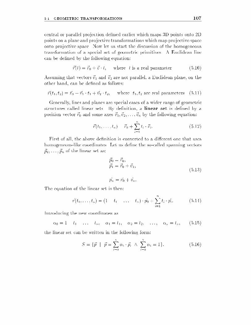
central or parallel projection de�ned earlier which maps 3D points onto 2Dpoints on a plane and projective transformations which map projective spaceonto projective space. Now let us start the discussion of the homogeneoustransformation of a special set of geometric primitives. A Euclidean linecan be de�ned by the following equation:
~r(t) = ~r0 + ~v � t; where t is a real parameter. (5:10)
Assuming that vectors ~v1 and ~v2 are not parallel, a Euclidean plane, on theother hand, can be de�ned as follows:
~r(t1; t2) = ~r0 + ~v1 � t1 + ~v2 � t2; where t1; t2 are real parameters. (5:11)
Generally, lines and planes are special cases of a wider range of geometricstructures called linear sets. By de�nition, a linear set is de�ned by aposition vector ~r0 and some axes ~v1; ~v2; : : : ; ~vn by the following equation:
~r(t1; : : : ; tn) = ~r0 +nX
i=1
ti � ~vi: (5:12)
First of all, the above de�nition is converted to a di�erent one that useshomogeneous-like coordinates. Let us de�ne the so-called spanning vectors~p0; : : : ; ~pn of the linear set as:
~p0 = ~r0;
~p1 = ~r0 + ~v1;...~pn = ~r0 + ~vn:
(5:13)
The equation of the linear set is then:
~r(t1; : : : ; tn) = (1� t1 � : : :� tn) � ~p0 +nX
i=1
ti � ~pi: (5:14)
Introducing the new coordinates as
�0 = 1� t1 � : : :� tn; �1 = t1; �2 = t2; : : : ; �n = tn; (5:15)
the linear set can be written in the following form:
S = f~p j ~p =nX
i=0
�i � ~pi ^nX
i=0
�i = 1g: (5:16)

108 5. TRANSFORMATIONS, CLIPPING AND PROJECTION
The weights (�i) are also called the baricentric coordinates of the point~p with respect to ~p0, ~p1,: : : ,~pn. This name re ects the interpretation that ~pwould be the center of gravity of a structure of weights (�0; �1; : : : ; �n) atpoints ~p0; ~p1; : : : ; ~pn.The homogeneous transformation of such a point ~p is:
[~p; 1] �T = [nX
i=0
�i � ~pi; 1] �T = [nX
i=0
�i � ~pi;nXi=0
�i] �T =
(nX
i=0
�i � [~pi; 1]) �T =nX
i=0
�i � ([~pi; 1] �T) (5:17)
sincePn
i=0 �i = 1. Denoting [~pi; 1] �T by [~Pi; hi] we get:
[~p; 1] �T =nXi=0
�i � [~Pi; hi] = [nX
i=0
�i � ~Pi;nX
i=0
�i � hi]: (5:18)
If the resulting fourth coordinatePn
i=0 �i � hi is zero, then the point ~p ismapped onto an ideal point, therefore it cannot be converted back to Eu-clidean space. These ideal points must be eliminated before the homoge-neous division (see section 5.5 on clipping).After homogeneous division we are left with:
[nX
i=0
�i � hiPnj=1 �j � hj
�~Pi
hi; 1] = [
nXi=0
��i � ~p�
i ; 1] (5:19)
where ~p �
i is the homogeneous transformation of ~pi. The derivation of ��iguarantees that
Pni=0 �
�
i = 1. Thus, the transformation of the linear set isalso linear. Examining the expression of the weights (��i ), we can concludethat generally �i 6= ��i meaning the homogeneous transformation may de-stroy equal spacing. In other words the division ratio is not projectiveinvariant. In the special case when the transformation is a�ne, coordinateshi will be 1, thus �i = ��i , which means that equal spacing (or divisionratio) is a�ne invariant.A special type of linear set is the convex hull. The convex hull is de�ned
by equation 5.16 with the provision that the baricentric coordinates mustbe non-negative.

5.1. GEOMETRIC TRANSFORMATIONS 109
To avoid the problems of mapping onto ideal points, let us assume thespanning vectors to be mapped onto the same side of the h = 0 hyper-plane, meaning that the hi-s must have the same sign. This, with �i � 0,guarantees that no points are mapped onto ideal points and
��i =nX
i=0
�i � hiPni=0 �i � hi
� 0 (5:20)
Thus, baricentric coordinates of the image will also be non-negative, thatis, convex hulls are also mapped onto convex hulls by homogeneous trans-formations if their transformed image does not contain ideal points. Anarbitrary planar polygon can be broken down into triangles that are convexhulls of three spanning vectors. The transformation of this polygon willbe the composition of the transformed triangles. This means that a planarpolygon will also be preserved by homogeneous transformations if its imagedoes not intersect with the h = 0 plane.As mentioned earlier, in computer graphics the objects are de�ned in
Euclidean space by Cartesian coordinates and the image is required in a 2Dpixel space that is also Euclidean with its coordinates which correspond tothe physical pixels of the frame bu�er. Projective geometry may be neededonly for speci�c stages of the transformation from modeling to pixel space.Since projective space can be regarded as an extension of the Euclideanspace, the theory of transformations could be discussed generally only inprojective space. For pedagogical reasons, however, we will use the morecomplicated homogeneous representations if they are really necessary forcomputer graphics algorithms, and deal with the Cartesian coordinates insimpler cases. This combined view of Euclidean and projective geometriesmay be questionable from a purely mathematical point of view, but it isaccepted by the computer graphics community because of its clarity and itselimination of unnecessary abstractions.We shall consider the transformation of points in this section, which will
lead on to the transformation of planar polygons as well.

110 5. TRANSFORMATIONS, CLIPPING AND PROJECTION
5.1.1 Elementary transformations
Translation
Translation is a very simple transformation that adds the translation vector~p to the position vector ~r of the point to be transformed:
~r 0 = ~r + ~p: (5:21)
Scaling along the coordinate axes
Scaling modi�es the distances and the size of the object independently alongthe three coordinate axes. If a point originally has [x; y; z] coordinates, forexample, after scaling the respective coordinates are:
x0 = Sx � x; y0 = Sy � y; z0 = Sz � z: (5:22)
This transformation can also be expressed by a matrix multiplication:
~r 0 = ~r �
264Sx 0 00 Sy 00 0 Sz
375 : (5:23)
Rotation around the coordinate axes
Rotating around the z axis by an angle �, the x and y coordinates of a pointare transformed according to �gure 5.3, leaving coordinate z una�ected.
y
φ
(x’,y’)
(x,y)
xz
Figure 5.3: Rotation around the z axis
By geometric considerations, the new x; y coordinates can be expressedas:
x0 = x � cos �� y � sin �; y0 = x � sin�+ y � cos�: (5:24)

5.1. GEOMETRIC TRANSFORMATIONS 111
Rotations around the y and x axes have similar form, just the roles of x; yand z must be exchanged. These formulae can also be expressed in matrixform:
~r 0(x; �) = ~r �
2641 0 00 cos � sin�0 � sin � cos �
375
~r 0(y; �) = ~r �
264cos � 0 � sin �0 1 0
sin� 0 cos �
375
~r 0(z; �) = ~r �
264
cos � sin � 0� sin� cos� 0
0 0 1
375 :
(5:25)
These rotations can be used to express any orientation [Lan91]. Supposethat K and K 000 are two Cartesian coordinate systems sharing a commonorigin but having di�erent orientations. In order to determine three specialrotations around the coordinate axes which transform K into K 000, let usde�ne a new Cartesian system K 0 such that its z0 axis is coincident with z
and its y0 axis is on the intersection line of planes [x; y] and [x000; y000]. Totransform axis y onto axis y0 a rotation is needed around z by angle �. Thena new rotation around y0 by angle � has to be applied that transforms x0
into x000 resulting in a coordinate system K 00. Finally the coordinate systemK 00 is rotated around axis x00 = x000 by an angle to transform y00 into y000.The three angles, de�ning the �nal orientation, are called roll, pitch and
yaw angles. If the roll, pitch and yaw angles are �, � and respectively,the transformation to the new orientation is:
~r 0 = ~r �
264
cos� sin� 0� sin� cos� 0
0 0 1
375 �264cos� 0 � sin�0 1 0
sin � 0 cos�
375 �2641 0 00 cos sin 0 � sin cos
375 :
(5:26)
Rotation around an arbitrary axis
Let us examine a linear transformation that corresponds to a rotation byangle � around an arbitrary unit axis ~t going through the origin. The origi-nal and the transformed points are denoted by vectors ~u and ~v respectively.

112 5. TRANSFORMATIONS, CLIPPING AND PROJECTION
Let us decompose vectors ~u and ~v into perpendicular (~u?; ~v?) and parallel(~uk; ~vk) components with respect to ~t. By geometrical considerations we canwrite:
~uk = ~t(~t � ~u)
~u? = ~u� ~uk = ~u� ~t(~t � ~u) (5.27)
Since the rotation does not a�ect the parallel component, ~vk = ~uk.
φu
t
t
||u ||
u
v
v
=v
x u
Figure 5.4: Rotating around ~t by angle �
Since vectors ~u?; ~v? and ~t � ~u? = ~t � ~u are in the plane perpendicularto ~t, and ~u? and ~t � ~u? are perpendicular vectors (�gure 5.4), ~v? can beexpressed as:
~v? = ~u? � cos�+ ~t� ~u? � sin�: (5:28)
Vector ~v, that is the rotation of ~u, can then be expressed as follows:
~v = ~vk + ~v? = ~u � cos �+ ~t� ~u � sin�+ ~t(~t � ~u)(1 � cos �): (5:29)
This equation, also called theRodrigues formula, can also be expressedin matrix form. Denoting cos� and sin� by C� and S� respectively andassuming ~t to be a unit vector, we get:
~v = ~u �
264
C�(1 � t2x) + t2x txty(1� C�) + S�tz txtz(1 � C�)� S�tytytx(1 �C�)� S�tz C�(1 � t2y) + t2y txtz(1 �C�) + S�txtztx(1� C�) + S�ty tzty(1� C�)� S�tx C�(1 � t2z) + t2z
375 :
(5:30)

5.2. TRANSFORMATION TO CHANGE THE COORDINATE SYSTEM 113
It is important to note that any orientation can also be expressed asa rotation around an appropriate axis. Thus, there is a correspondencebetween roll-pitch-yaw angles and the axis and angle of �nal rotation, whichcan be given bymaking the two transformation matrices de�ned in equations5.26 and 5.30 equal and solving the equation for unknown parameters.
Shearing
Suppose a shearing stress acts on a block �xed on the xy face of �gure 5.5,deforming the block to a parallepiped. The transformation representing thedistortion of the block leaves the z coordinate una�ected, and modi�es thex and y coordinates proportionally to the z coordinate.
x
y
z
Figure 5.5: Shearing of a block
In matrix form the shearing transformation is:
~r 0 = ~r �
2641 0 00 1 0a b 1
375 : (5:31)
5.2 Transformation to change the
coordinate system
Objects de�ned in one coordinate system are often needed in another co-ordinate system. When we decide to work in several coordinate systemsand to make every calculation in the coordinate system in which it is the

114 5. TRANSFORMATIONS, CLIPPING AND PROJECTION
simplest, the coordinate system must be changed for each di�erent phase ofthe calculation.Suppose unit coordinate vectors ~u, ~v and ~w and the origin ~o of the new
coordinate system are de�ned in the original x; y; z coordinate system:
~u = [ux; uy; uz]; ~v = [vx; vy; vz]; ~w = [wx; wy; wz]; ~o = [ox; oy; oz]: (5:32)
Let a point ~p have x; y; z and �; �; coordinates in the x; y; z and in theu; v; w coordinate systems respectively. Since the coordinate vectors ~u;~v; ~was well as their origin, ~o, are known in the x; y; z coordinate system, ~p canbe expressed in two di�erent forms:
~p = � � ~u+ � � ~v + � ~w + ~o = [x; y; z]: (5:33)
This equation can also be written in homogeneous matrix form, havingintroduced the matrix formed by the coordinates of the vectors de�ning theu; v; w coordinate system:
Tc =
26664ux uy uz 0vx vy vz 0wx wy wz 0ox oy oz 1
37775 ; (5:34)
[x; y; z; 1] = [�; �; ; 1] �Tc: (5:35)
Since Tc is always invertible, the coordinates of a point of the x; y; z
coordinate system can be expressed in the u; v; w coordinate system as well:
[�; �; ; 1] = [x; y; z; 1] �Tc�1: (5:36)
Note that the inversion of matrixTc can be calculated quite e�ectively sinceits upper-left minor matrix is orthonormal, that is, its inverse is given bymirroring the matrix elements onto the diagonal of the matrix, thus:
T�1c =
26664
1 0 0 00 1 0 00 0 1 0�ox �oy �oz 1
37775 �26664ux vx wx 0uy vy wy 0uz vz wz 00 0 0 1
37775 : (5:37)

5.3. DEFINITION OF THE CAMERA 115
5.3 De�nition of the camera
Having de�ned transformation matrices we can now look at their use inimage generation, but �rst some basic de�nitions.In 3D image generation, a window rectangle is placed into the 3D space
of the virtual world with arbitrary orientation, a camera or eye is putbehind the window, and a photo is taken by projecting the model onto thewindow plane, supposing the camera to be the center of projection, andignoring the parts mapped outside the window rectangle or those which arenot in the speci�ed region in front of the camera. The data, which de�nehow the virtual world is looked at, are called camera parameters, andinclude:
vrp
x
y
z
uv
w
bp
fb
eye
window
front clipping plane
vpn
Figure 5.6: De�nition of the camera
� Position and orientation of the window. The center of the win-dow, called the view reference point, is de�ned as a point, or avector ~vrp, in the world coordinate system. The orientation is de�nedby a u; v; w orthogonal coordinate system, which is also called thewindow coordinate system, centered at the view reference point,with ~u and ~v specifying the direction of the horizontal and verticalsides of the window rectangle, and ~w determining the normal of theplane of the window. Unit coordinate vectors ~u;~v; ~w are obviously

116 5. TRANSFORMATIONS, CLIPPING AND PROJECTION
not independent, because each of them is perpendicular to the othertwo, thus that dependence has also to be taken care of during thesetting of camera parameters. To ease the parameter setting phase,instead of specifying the coordinate vector triple, two almost inde-pendent vectors are used for the de�nition of the orientation, whichare the normal vector to the plane of the window, called the viewplane normal, or ~vpn for short, and a so-called view up vector, or~vup, whose component that is perpendicular to the normal and is inthe plane of ~vpn and ~vup de�nes the direction of the vertical edge ofthe window. There is a slight dependence between them, since theyshould not be parallel, that is, it must always hold that ~vup� ~vpn 6= 0.The ~u;~v; ~w coordinate vectors can easily be calculated from the viewplane normal and the view up vectors:
~w =~vpn
j ~vpnj; ~u =
~w � ~vup
j~w � ~vupj; ~v = ~u� ~w: (5:38)
Note that unlike the x; y; z world coordinate system, the u; v; w systemhas been de�ned left handed to meet the user's expectations that ~upoints to the right, ~v points upwards and ~w points away from thecamera located behind the window.
� Size of the window. The length of the edges of the window rectangleare de�ned by two positive numbers, the width by wwidth, the heightby wheight. Photographic operations, such as zooming in and out,can be realized by proper control of the size of the window. To avoiddistortions, the width/height ratio has to be equal to width/heightratio of the viewport on the screen.
� Type of projection. The image is the projection of the virtual worldonto the window. Two di�erent types of projection are usually usedin computer graphics, the parallel projection (if the projectors areparallel), and the perspective projection (if all the projectors gothrough a given point, called the center of projection). Parallel pro-jections are further classi�ed into orthographic and oblique projec-tions depending on whether or not the projectors are perpendicular tothe plane of projection (window plane). The attribute \oblique" mayalso refer to perspective projection if the projector from the center of

5.3. DEFINITION OF THE CAMERA 117
the window is not perpendicular to the plane of the window. Obliqueprojections may cause distortion of the image.
� Location of the camera or eye. The camera is placed behindthe window in our conceptual model. For perspective projection, thecamera position is, in fact, the center of projection, which can bede�ned by a point ~eye in the u; v; w coordinate system. For parallelprojection, the direction of the projectors has to be given by the u; v; wcoordinates of the direction vector. Both in parallel and perspectiveprojections the depth coordinate w is required to be negative in orderto place the camera \behind" the window. It also makes sense toconsider parallel projection as a special perspective projection, whenthe camera is at an in�nite distance from the window.
� Front and back clipping planes. According to the conceptualmodel of taking photos of the virtual world, it is obvious that onlythose portions of the model which lie in the in�nite pyramid de�nedby the camera as the apex, and the sides of the 3D window (for per-spective projection), and in a half-open, in�nite parallelepiped (forparallel projection) can a�ect the photo. These in�nite regions areusually limited to a �nite frustum of a pyramid, or to a �nite par-allelepiped respectively, to avoid over ows and also to ease the pro-jection task by eliminating the parts located behind the camera, byde�ning two clipping planes called the front clipping plane and theback clipping plane. These planes are parallel with the windowand thus have constant w coordinates appropriate for the de�nition.Thus the front plane is speci�ed by an fp value, meaning the planew = fp, and the back plane is de�ned by a bp value. Consideringthe objectives of the clipping planes, their w coordinates have to begreater than the w coordinate of the eye, and fp < bp should alsohold.

118 5. TRANSFORMATIONS, CLIPPING AND PROJECTION
5.4 Viewing transformation
Image generation involves:
1. the projection of the virtual world onto the window rectangle,
2. the determination of the closest surface at each point (visibility calcu-lation) by depth comparisons if more than one surface can be projectedonto the same point in the window, and
3. the placement of the result in the viewport rectangle of the screen.
Obviously, the visibility calculation has to be done prior to the projection ofthe 3D space onto the 2D window rectangle, since this projection destroysthe depth information.These calculations could also be done in the world coordinate system,
but each projection would require the evaluation of the intersection of anarbitrary line and rectangle (window), and the visibility problem wouldrequire the determination of the distance of the surface points along theprojectors. The large number of multiplications and divisions required bysuch geometric computations makes the selection of the world coordinatesystem disadvantageous even if the required calculations can be reduced bythe application of the incremental concept, and forces us to look for othercoordinate systems where these computations are simple and e�ective toperform.In the optimal case the points should be transformed to a coordinate
system where X;Y coordinates would represent the pixel location throughwhich the given point is visible, and a third Z coordinate could be used todecide which point is visible, i.e. closest to the eye, if several points couldbe transformed to the same X;Y pixel. Note that Z is not necessarily pro-portional to the distance from the eye, it should only be a monotonouslyincreasing function of the distance. The appropriate transformation is alsoexpected to map lines onto lines and planes onto planes, allowing simplerepresentations and linear interpolations during clipping and visibility cal-culations. Coordinate systems meeting all the above requirements are calledscreen coordinate systems. In a coordinate system of this type, the visi-bility calculations are simple, since should two or more points have the sameX;Y pixel coordinates, then the visible one has the smallest Z coordinate.

5.4. VIEWING TRANSFORMATION 119
From a di�erent perspective, if it has to be decided whether one point willhide another, two comparisons are needed to check whether they projectonto the same pixel, that is, whether they have the same X;Y coordinates,and a third comparison must be used to select the closest. The projectionis very simple, because the projected point has, in fact, X;Y coordinatesdue to the de�nition of the screen space.For pedagogical reasons, the complete transformation is de�ned through
several intermediate coordinate systems, although eventually it can be ac-complished by a single matrix multiplication. For both parallel and perspec-tive cases, the �rst step of the transformation is to change the coordinatesystem to u; v; w from x; y; z, but after that there will be di�erences de-pending on the projection type.
5.4.1 World to window coordinate system
transformation
First, the world is transformed to the u; v; w coordinate system �xed to thecenter of the window. Since the coordinate vectors ~u, ~v, ~w and the origin~vrp are de�ned in the x; y; z coordinate system, the necessary transforma-tion can be developed based on the results of section 5.2 of this chapter.The matrix formed by the coordinates of the vectors de�ning the u; v; w
coordinate system is:
Tuvw =
26664
ux uy uz 0vx vy vz 0wx wy wz 0vrpx vrpy vrpz 1
37775 ; (5:39)
[x; y; z; 1] = [�; �; ; 1] �Tuvw: (5:40)
Since ~u, ~v, ~w are perpendicular vectors, Tuvw is always invertible. Thus,the coordinates of an arbitrary point of the world coordinate system can beexpressed in the u; v; w coordinate system as well:
[�; �; ; 1] = [x; y; z; 1] �T�1uvw: (5:41)

120 5. TRANSFORMATIONS, CLIPPING AND PROJECTION
5.4.2 Window to screen coordinate system
transformation for parallel projection
Shearing transformation
For oblique transformations, that is when eyeu or eyev is not zero, the pro-jectors are not perpendicular to the window plane, thus complicating visi-bility calculations and projection (�gure 5.7). This problem can be solvedby distortion of the object space, applying a shearing transformation insuch a way that the non-oblique projection of the distorted objects shouldprovide the same images as the oblique projection of the original scene,and the depth coordinate of the points should not be a�ected. A general
w
(0,0,eye )w
P=eyewindow
Figure 5.7: Shearing
shearing transformation which does not a�ect the w coordinate is:
Tshear =
26664
1 0 0 00 1 0 0su sv 1 00 0 0 1
37775 : (5:42)
The unknown elements, su and sv, can be determined by examining thetransformation of the projector ~P = [eyeu; eyev; eyew; 1]. The transformedprojector is expected to be perpendicular to the window and to have depthcoordinate eyew, that is:
~P �Tshear = [0; 0; eyew; 1]: (5:43)

5.4. VIEWING TRANSFORMATION 121
Using the de�nition of the shearing transformation, we get:
su = �eyeu
eyew; sv = �
eyev
eyew: (5:44)
Normalizing transformation
Having accomplished the shearing transformation, the objects for parallelprojection are in a space shown in �gure 5.8. The subspace which can beprojected onto the window is a rectangular box between the front and backclipping plane, having side faces coincident to the edges of the window.To allow uniform treatment, a normalizing transformation can be applied,which maps the box onto a normalized block, called the canonical viewvolume, moving the front clipping plane to 0, the back clipping plane to1, the other boundaries to x = 1, y = 1, x = �1 and y = �1 planesrespectively.
fp
window
bp
w 1
-1
1v
Figure 5.8: Normalizing transformation for parallel projection
The normalizing transformation can also be expressed in matrix form:
Tnorm =
266642=wwidth 0 0 0
0 2=wheight 0 00 0 1=(bp � fp) 00 0 �fp=(bp � fp) 1
37775 : (5:45)
The projection in the canonical view volume is very simple, since theprojection does not a�ect the (X;Y ) coordinates of an arbitrary point, butonly its depth coordinate.
122 5. TRANSFORMATIONS, CLIPPING AND PROJECTION
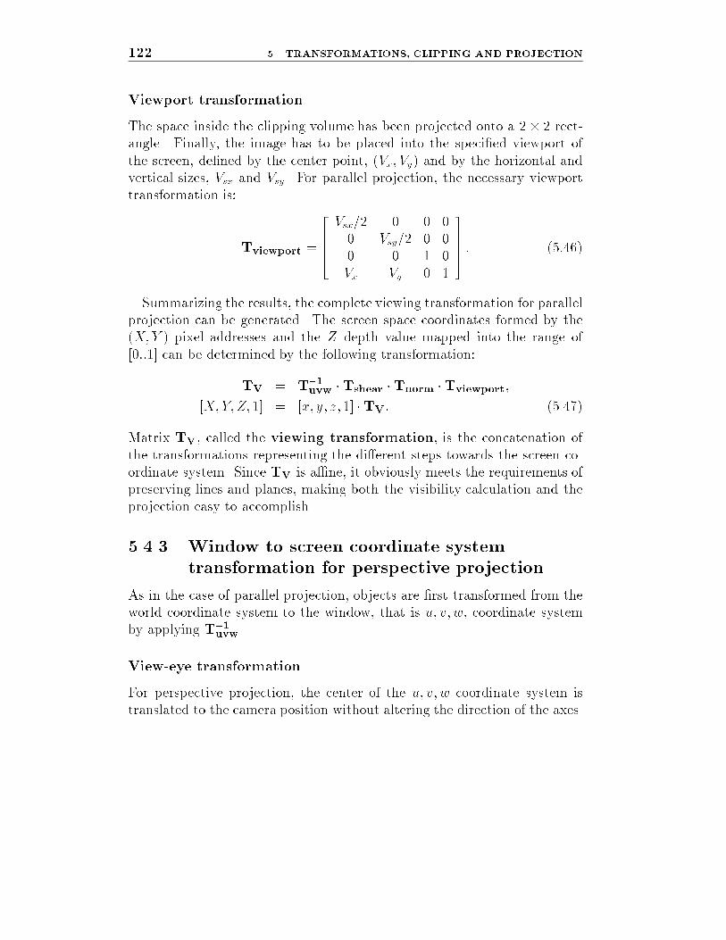
Viewport transformation
The space inside the clipping volume has been projected onto a 2� 2 rect-angle. Finally, the image has to be placed into the speci�ed viewport ofthe screen, de�ned by the center point, (Vx; Vy) and by the horizontal andvertical sizes, Vsx and Vsy. For parallel projection, the necessary viewporttransformation is:
Tviewport =
26664Vsx=2 0 0 00 Vsy=2 0 00 0 1 0Vx Vy 0 1
37775 : (5:46)
Summarizing the results, the complete viewing transformation for parallelprojection can be generated. The screen space coordinates formed by the(X;Y ) pixel addresses and the Z depth value mapped into the range of[0::1] can be determined by the following transformation:
TV = T�1uvw �Tshear �Tnorm �Tviewport;
[X;Y;Z; 1] = [x; y; z; 1] �TV: (5.47)
Matrix TV, called the viewing transformation, is the concatenation ofthe transformations representing the di�erent steps towards the screen co-ordinate system. Since TV is a�ne, it obviously meets the requirements ofpreserving lines and planes, making both the visibility calculation and theprojection easy to accomplish.
5.4.3 Window to screen coordinate system
transformation for perspective projection
As in the case of parallel projection, objects are �rst transformed from theworld coordinate system to the window, that is u; v; w, coordinate systemby applying T�1
uvw.
View-eye transformation
For perspective projection, the center of the u; v; w coordinate system istranslated to the camera position without altering the direction of the axes.
5.4. VIEWING TRANSFORMATION 123
Since the camera is de�ned in the u; v; w coordinate system by a vector~eye, this transformation is a translation by vector � ~eye, which can also beexpressed by a homogeneous matrix:
Teye =
26664
1 0 0 00 1 0 00 0 1 0
�eyeu �eyev �eyew 1
37775 : (5:48)
Shearing transformation
As for parallel projection, if eyeu or eyev is not zero, the projector from thecenter of the window is not perpendicular to the window plane, requiringthe distortion of the object space by a shearing transformation in sucha way that the non-oblique projection of the distorted objects provides thesame images as the oblique projection of the original scene and the depthcoordinate of the points is not a�ected. Since the projector from the centerof the window (~P = [eyeu; eyev; eyew; 1]) is the same as all the projectorsfor parallel transformation, the shearing transformation matrix will havethe same form, independently of the projection type:
Tshear =
26664
1 0 0 00 1 0 0
�eyeu=eyew �eyev=eyew 1 00 0 0 1
37775 : (5:49)
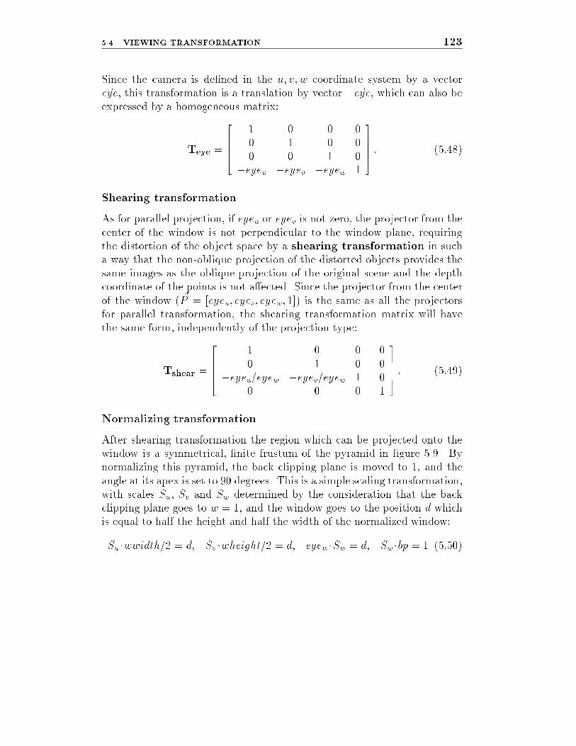
Normalizing transformation
After shearing transformation the region which can be projected onto thewindow is a symmetrical, �nite frustum of the pyramid in �gure 5.9. Bynormalizing this pyramid, the back clipping plane is moved to 1, and theangle at its apex is set to 90 degrees. This is a simple scaling transformation,with scales Su, Sv and Sw determined by the consideration that the backclipping plane goes to w = 1, and the window goes to the position d whichis equal to half the height and half the width of the normalized window:
Su �wwidth=2 = d; Sv �wheight=2 = d; eyew �Sw = d; Sw �bp = 1 (5:50)

124 5. TRANSFORMATIONS, CLIPPING AND PROJECTION
fp window bp
w
1
bp
fp
window
d
w
Figure 5.9: Normalizing transformation for perspective projection
Solving these equations and expressing the transformation in a homoge-neous matrix form, we get:
Tnorm =
266642 � eyew=(wwidth � bp) 0 0 0
0 2 � eyew=(wheight � bp) 0 00 0 1=bp 00 0 0 1
37775 :
(5:51)In the canonical view volume, the central projection of a point Xc; Yc; Zc
onto the window plane is:
Xp = d �Xc
Zc
; Yp = d �Yc
Zc
: (5:52)
Perspective transformation
The projection and the visibility calculations are more di�cult in the canon-ical view volume for central projection than they are for parallel projectionbecause of the division required by the projection. When calculating vis-ibility, it has to be decided if one point (X1
c ; Y1c ; Z
1c ) hides another point
(X2c ; Y
2c ; Z
2c ). This involves the check for relations
[X1c =Z
1c ; Y
1c =Z
1c ] = [X2
c =Z2c ; Y
2c =Z
2c ] and Z1
c < Z2c
which requires division in a way that the visibility check for parallel projec-tion does not. To avoid division during the visibility calculation, a transfor-mation is needed which transforms the canonical view volume to meet the

5.4. VIEWING TRANSFORMATION 125
requirements of the screen coordinate systems, that is, X and Y coordinatesare the pixel addresses in which the point is visible, and Z is a monotonousfunction of the original distance from the camera (see �gure 5.10).
1
1
V ,Vx yV ,Vsx sy
canonical view volume screen coordinate system
eye
Figure 5.10: Canonical view volume to screen coordinate system transformation
Considering the expectations for the X and Y coordinates:
X =Xc
Zc
�Vsx
2+ Vx; Y =
Yc
Zc
�Vsy
2+ Vy : (5:53)
The unknown function Z(Zc) can be determined by forcing the transforma-tion to preserve planes and lines. Suppose a set of points of the canonicalview volume are on a plane with the equation:
a �Xc + b � Yc + c � Zc + d = 0 (5:54)
The transformation of this set is also expected to lie in a plane, that is, thereare parameters a0; b;0 c;0 d0 satisfying the equation of the plane for trans-formed points:
a0 �X + b0 � Y + c0 � Z + d0 = 0 (5:55)
Inserting formula 5.53 into this plane equation and multiplying both sidesby Zc, we get:
a0 �Vsx
2�Xc+ b0 �
Vsy
2�Yc+ c0 �Z(Zc) �Zc+(a0 �Vx+ b0 �Vy+d0) �Zc = 0 (5:56)

126 5. TRANSFORMATIONS, CLIPPING AND PROJECTION
Comparing this with equation 5.54, we can conclude that both Z(Zc) � Zc
and Zc are linear functions of Xc and Yc, requiring Z(Zc) �Zc to be a linearfunction of Zc also. Consequently:
Z(Zc) � Zc = � � Zc + � =) Z(Zc) = �+�
Zc
: (5:57)
Unknown parameters � and � are set to map the front clipping plane ofthe canonical view volume (fp0 = fp=bp) to 0 and the back clipping plane(1) to 1:
� � fp0 + � = 0; � � 1 + � = 1+
� = bp=(bp � fp); � = �fp=(bp � fp)(5:58)
The complete transformation, called the perspective transformation,is:
X =Xc
Zc
�Vsx
2+ Vx; Y =
Yc
Zc
�Vsy
2+ Vy; Z =
Zc � bp � fp
(bp� fp) � Zc
: (5:59)
Examining equation 5.59, we can see that X �Zc, Y �Zc and Z �Zc can beexpressed as a linear transformation of Xc; Yc; Zc, that is, in homogeneouscoordinates [Xh; Yh; Zh; h] = [X �Zc; Y �Zc, Z �Zc; Zc] can be calculated witha single matrix product by Tpersp:
Tpersp =
26664Vsx=2 0 0 00 Vsy=2 0 0Vx Vy bp=(bp � fp) 10 0 �fp=(bp � fp) 0
37775 : (5:60)
The complete perspective transformation, involving homogeneous divi-sion to get real 3D coordinates, is:
[Xh; Yh; Zh; h] = [Xc; Yc; Zc; 1] �Tpersp;
[X;Y;Z; 1] = [Xh
h;Yh
h;Zh
h; 1]: (5:61)
The division by coordinate h is meaningful only if h 6= 0. Note that thecomplete transformation is a homogeneous linear transformation which con-sists of a matrix multiplication and a homogeneous division to convert thehomogeneous coordinates back to Cartesian ones.

5.4. VIEWING TRANSFORMATION 127
This is not at all surprising, since one reason for the emergence of projec-tive geometry has been the need to handle central projection somehow bylinear means. In fact, the result of equation 5.61 could have been derivedeasily if it had been realized �rst that a homogeneous linear transformationwould solve the problem (�gure 5.10). This transformation would transformthe eye onto an ideal point and make the side faces of the viewing pyramidparallel. Using homogeneous coordinates this transformation means that:
T : [0; 0; 0; 1] 7! �1[0; 0;�1; 0]: (5:62)
Multiplicative factor �1 indicates that all homogeneous points di�ering bya scalar factor are equivalent. In addition, the corner points where the sidefaces and the back clipping plane meet should be mapped onto the cornerpoints of the viewport rectangle on the Z = 1 plane and the front clippingplane must be moved to the origin, thus:
T : [1; 1; 1; 1] 7! �2[Vx + Vsx=2; Vy + Vsy=2; 1; 1];T : [1;�1; 1; 1] 7! �3[Vx + Vsx=2; Vy � Vsy=2; 1; 1];T : [�1; 1; 1; 1] 7! �4[Vx � Vsx=2; Vy + Vsy=2; 1; 1];T : [0; 0; fp0; 1] 7! �5[Vx; Vy; 0; 1]:
(5:63)
Transformation T is de�ned by a matrix multiplication with T4�4. Itsunknown elements can be determined by solving the linear system of equa-tions generated by equations 5.62 and 5.63. The problem is not determinantsince the number of equations (20) is one less than the number of variables(21). In fact, it is natural, since scalar multiples of homogeneous matricesare equivalent. By setting �2 to 1, however, the problem will be determinantand the resulting matrix will be the same as derived in equation 5.60.As has been proven, homogeneous transformation preserves linear sets
such as lines and planes, thus deriving this transformation from the re-quirement that it should preserve planes also guaranteed the preservationof lines.However, when working with �nite structures, such as line segments, poly-
gons, convex hulls, etc., homogeneous transformations can cause seriousproblems if the transformed objects intersect the h = 0 hyperplane. (Notethat the preservation of convex hulls could be proven for only those caseswhen the image of transformation has no such intersection.)To demonstrate this problem and how perspective transformation works,
consider an example when Vx = Vy = 0; Vsx = Vsy = 2; fp = 0:5; bp = 1 and

128 5. TRANSFORMATIONS, CLIPPING AND PROJECTION
x
h=
h
z
h
z
x
h
z
x
1. Canonical view volume in 3D Euclidean space
an Euclidean line segment
2. After the perspective transformation
3. After the homogenous division
line segment with wrap-around
eye
eye’
eye’’
intersection with
8
"points"
AB
A’
B’
B’’A’’
1
h=1
h=1
h=0 plane
Figure 5.11: Steps of the perspective transformation and the wrap-around
problem

5.4. VIEWING TRANSFORMATION 129
examine what happens with the clipping region and with a line segmentde�ned by endpoints [0.3,0,0.6] and [0.3,0,-0.6] in the Cartesian coordinatesystem (see �gure 5.11). This line segment starts in front of the eye and goesbehind it. When the homogeneous representation of this line is transformedby multiplying the perspective transformation matrix, the line will intersectthe h = 0 plane, since originally it intersects the Zc = 0 plane (which isparallel with the window and contains the eye) and the matrixmultiplicationsets h = Zc. Recall that the h = 0 plane corresponds to the ideal points inthe straight model, which have no equivalent in Euclidean geometry.The conversion of the homogeneous coordinates to Cartesian ones by ho-
mogeneous division maps the upper part corresponding to positive h valuesonto a Euclidean half-line and maps the lower part corresponding to neg-ative h values onto another half-line. This means that the line segmentfalls into two half-lines, a phenomenon which is usually referred to as thewrap-around problem.Line segments are identi�ed by their two endpoints in computer graph-
ics. If wrap-around phenomena may occur we do not know whether thetransformation of the two endpoints really de�ne the new segment, or theseare the starting points of two half-lines that form the complement of theEuclidean segment. This is not surprising in projective geometry, since aprojective version of a Euclidean line, for example, also includes an idealpoint in addition to all a�ne points, which glues the two \ends" of the lineat in�nity. From this point of view projective lines are similar (more pre-cisely isomorphic) to circles. As two points on a circle cannot identify an arcunambiguously, two points on a projective line cannot de�ne a segment ei-ther without further information. By knowing, however, that the projectiveline segment does not contain ideal points, this de�nition is unambiguous.The elimination of ideal points from the homogeneous representation be-
fore homogeneous division obviously solves the problem. Before the homo-geneous division, this procedure cuts the objects represented by homoge-neous coordinates into two parts corresponding to the positive and negativeh values respectively, then projects these parts back to the Cartesian co-ordinates separately and generates the �nal representation as the union ofthe two cases. Recall that a clipping that removes object parts locatedoutside of the viewing pyramid must be accomplished somewhere in theviewing pipeline. The cutting proposed above is worth combining with thisclipping step, meaning that the clipping (or at least the so-called depth clip-

130 5. TRANSFORMATIONS, CLIPPING AND PROJECTION
ping phase that can remove the vanishing plane which is transformed ontoideal points) must be carried out before homogeneous division. Clipping isaccomplished by appropriate algorithms discussed in the next section.Summarizing the transformation steps of viewing for the perspective case,
the complete viewing transformation is:
TV = T�1uvw �Teye �Tshear �Tnorm �Tpersp;
[Xh; Yh; Zh; h] = [x; y; z; 1] �TV;
[X;Y;Z; 1] = [Xh
h;Yh
h;Zh
h; 1]: (5.64)
5.5 Clipping
Clipping is responsible for eliminating those parts of the scene which do notproject onto the window rectangle, because they are outside the viewingvolume. It consists of depth | front and back plane | clipping and clippingat the side faces of the volume. For perspective projection, depth clipping isalso necessary to solve the wrap-around problem, because it eliminates theobjects in the plane parallel to the window and incident to the eye, whichare mapped onto the ideal plane by the perspective transformation.For parallel projection, depth clipping can be accomplished in any co-
ordinate system before the projection, where the depth information is stillavailable. The selection of the coordinate system in which the clipping isdone may depend on e�ciency considerations, or more precisely:
1. The geometry of the clipping region has to be simple in the selectedcoordinate system in order to minimize the number of necessary op-erations.
2. The transformation to the selected coordinate system from the worldcoordinate system and from the selected coordinate system to pixelspace should involve the minimum number of operations.
Considering the �rst requirement, for parallel projection, the brick shapedcanonical view volume of the normalized eye coordinate system and thescreen coordinate system are the best, but, unlike the screen coordinatesystem, the normalized eye coordinate system requires a new transformationafter clipping to get to pixel space. The screen coordinate system thus ranks

5.5. CLIPPING 131
as the better option. Similarly, for perspective projection, the pyramidshaped canonical view volume of the normalized eye and the homogeneouscoordinate systems require the simplest clipping calculations, but the latterdoes not require extra transformation before homogeneous division. For sideface clipping, the screen coordinate system needs the fewest operations, butseparating the depth and side face clipping phases might be disadvantageousfor speci�c hardware realizations. In the next section, the most general case,clipping in homogeneous coordinates, will be discussed. The algorithmsfor other 3D coordinate systems can be derived from this general case byassuming the homogeneous coordinate h to be constant.
5.5.1 Clipping in homogeneous coordinates
The boundaries of the clipping region can be derived by transforming the re-quirements of the screen coordinate system to the homogeneous coordinatesystem. After homogeneous division, in the screen coordinate system theboundaries are Xmin = Vx � Vsx=2, Xmax = Vx + Vsx=2, Ymin = Vy � Vsy=2and Ymax = Vy + Vsy=2. The points internal to the clipping region mustsatisfy:
Xmin � Xh=h � Xmax;
Ymin � Yh=h � Ymax;
0 � Zh=h � 1(5:65)
The visible parts of objects de�ned in an Euclidean world coordinatesystem must have positive Zc coordinates in the canonical view coordinatesystem, that is, they must be in front of the eye. Since multiplication bythe perspective transformation matrix sets h = Zc, for visible parts, thefourth homogeneous coordinate must be positive. Adding h > 0 to theset of inequalities 5.65 and multiplying both sides by this positive h, anequivalent system of inequalities can be derived as:
Xmin � h � Xh � Xmax � h;
Ymin � h � Yh � Ymax � h;
0 � Zh � h:
(5:66)
Note that inequality h > 0 does not explicitly appear in the requirements,since it comes from 0 � Zh � h. Inequality h > 0, on the other hand,guarantees that all points are eliminated that are on the h = 0 ideal plane,which solves the wrap-around problem.

132 5. TRANSFORMATIONS, CLIPPING AND PROJECTION
h=h
Z
X
h
Z
X
Z =
X = h Xmin
internal point
external point
h
h
h
h
Embedded screen coordinate system
4D homogenous space clipping plane:
clipping plane: 0
Z =hhclipping plane:
1
h=1
Figure 5.12: Transforming the clipping region back to projective space
Notice that the derivation of the homogeneous form of clipping has beenachieved by transforming the clipping box de�ned in the screen coordinatesystem back to the projective space represented by homogeneous coordi-nates (�gure 5.12).When the de�nition of the clipping region was elaborated, we supposed
that the objects are de�ned in a Cartesian coordinate system and reliedon the camera construction discussed in section 5.3. There are �elds ofcomputer graphics, however, where none of these is true. Sometimes it ismore convenient to de�ne the objects directly in the projective space byhomogeneous coordinates. A rational B-spline, for example, can be de�nedas a non-rational B-spline in homogeneous space, since the homogeneous toCartesian mapping will carry out the division automatically. When dealingwith homogeneous coordinates directly, scalar multiples of the coordinates

5.5. CLIPPING 133
are equivalent, thus both positive and negative h regions can contribute tothe visible section of the �nal space. Thus, equation 5.65 must be convertedto two system of inequalities, one supposing h > 0, the other h < 0.
Case 1: h > 0 Case 2: h < 0Xmin � h � Xh � Xmax � h Xmin � h � Xh � Xmax � h
Ymin � h � Yh � Ymax � h Ymin � h � Yh � Ymax � h
0 � Zh � h 0 � Zh � h
(5:67)
Clipping must be carried out for the two regions separately. After homo-geneous division these two parts will meet in the screen coordinate system.Even this formulation | which de�ned a front clipping plane in front
of the eye to remove points in the vanishing plane | may not be generalenough for systems where the clipping region is independent of the viewingtransformation like in PHIGS [ISO90]. In the more general case the imageof the clipping box in the homogeneous space may have intersection withthe ideal plane, which can cause wrap-around. The basic idea remains thesame in the general case; we must get rid of ideal points by some kind ofclipping. The interested reader is referred to the detailed discussion of thisapproach in [Kra89],[Her91].Now the clipping step is investigated in detail. Let us assume that the
clipping region is de�ned by equation 5.66 (the more general case of equa-tion 5.67 can be handled similarly by carrying out two clipping procedures).Based on equation 5.66 the clipping of points is very simple, since their
homogeneous coordinates must be examined to see if they satisfy all theequations. For more complex primitives, such as line segments and planarpolygons, the intersection of the primitive and the planes bounding the clip-ping region has to be calculated, and that part of the primitive should bepreserved where all points satisfy equation 5.66. The intersection calcula-tion of bounding planes with line segments and planar polygons requires thesolution of a linear equation involving multiplications and divisions. Thecase when there is no intersection happens when the solution for a parameteris outside the range of the primitive. The number of divisions and multi-plications necessary can be reduced by eliminating those primitive-planeintersection calculations which do not provide intersection, assuming thatthere is a simple way to decide which these are. Clipping algorithms containspecial geometric considerations to decide if there might be an intersectionwithout solving the linear equation.

134 5. TRANSFORMATIONS, CLIPPING AND PROJECTION
Clipping of line segments
One of the simplest algorithms for clipping line segments with fewer in-tersection calculations is the 3D extension of the Cohen and Sutherlandclipping algorithm.Each bounding plane of the clipping region divides the 3D space into two
half-spaces. Points in 3D space can be characterized by a 6-bit code, whereeach bit corresponds to a respective plane de�ning whether the given pointand the convex view volume are on opposite sides of the plane by 1 (or true)value, or on the same side of the plane, by 0 (or false) value. Formally thecode bits C[0] : : :C[5] of a point are de�ned by:
C[0] =�1 if Xh < Xmin � h
0 otherwiseC[1] =
�1 if Xh > Xmax � h
0 otherwise
C[2] =�1 if Yh < Ymin � h
0 otherwiseC[3] =
�1 if Yh > Ymax � h
0 otherwise
C[4] =�1 if Zh < 00 otherwise
C[5] =�1 if Zh > h
0 otherwise
(5:68)
Obviously, points coded by 000000 have to be preserved, while all othercodes correspond to regions outside the view volume (�gure 5.13).
000000
100010
101000101000
010100
000000
Figure 5.13: Clipping of line segments
Let the codes of the two endpoints of a line segment be C1 and C2 re-spectively. If both C1 and C2 are zero, the endpoints, as well as all inner

5.5. CLIPPING 135
points of the line segment, are inside the view volume, thus the whole linesegment has to be preserved by clipping. If the corresponding bits of bothC1 and C2 are non-zero at some position, then the endpoints, and the innerpoints too, are on the same side of the respective bounding plane, externalto the view volume, thus requiring the whole line segment to be eliminatedby clipping. These are the trivial cases where clipping can be accomplishedwithout any intersection calculation.If this is not the case | that is if at least one bit pair in the two codes are
not equal, and for those bits where they are the same, they have a value of 0,then the intersection between the line and that plane which corresponds tothe bit where the two codes are di�erent has to be calculated, and the partof the line segment which is outside must be eliminated by replacing theendpoint having 1 code bit by the intersection point. Let the two endpointshave coordinates [X
(1)
h ; Y(1)
h ; Z(1)
h ; h(1)] and [X(2)
h ; Y(2)
h ; Z(2)
h ; h(2)] respectively.The parametric representation of the line segment, supposing parameterrange [0::1] for t, is:
Xh(t) = X(1)
h � t+X(2)
h � (1� t)
Yh(t) = Y(1)
h � t+ Y(2)
h � (1 � t)
Zh(t) = Z(1)
h � t+ Z(2)
h � (1� t)
h(t) = h(1) � t+ h(2) � (1 � t)
(5.69)
Note that this representation expresses the line segment as a linear setspanned by the two endpoints. Special care has to be taken when the h
coordinates of the two endpoints have di�erent sign because this meansthat the linear set contains an ideal point as well.Now let us consider the intersection of this line segment with a clipping
plane (�gure 5.14). If, for example, the code bits are di�erent in the �rst bitcorresponding to Xmin, then the intersection with the plane Xh = Xmin � h
has to be calculated thus:
X(1)
h � t+X(2)
h � (1 � t) = Xmin � (h(1) � t+ h(2) � (1� t)): (5:70)
Solving for parameter t� of the intersection point, we get:
t� =Xmin � h
(2) �X(2)
h
X(1)
h �X(2)
h �Xmin � (h(1) � h(2)): (5:71)

136 5. TRANSFORMATIONS, CLIPPING AND PROJECTION
X h.minXh
X(2)h
(t ),*t = t =
hyperplane=
Y(2)h Z
(2)h h
(2)X
(1)h Y
(1)h Z
(1)h h
(1)
X h Yh Z h h(t ),* (t ),* (t )*
, , ,, , ,
10
Figure 5.14: Clipping by a homogeneous plane
Substituting t� back to the equation of the line segment, the homogeneouscoordinates of the intersection point are [Xh(t
�); Yh(t�); Zh(t
�); h(t�)]. Forother bounding planes, the algorithm is similar. The steps discussed canbe converted into an algorithm which takes and modi�es the two endpointsand returns TRUE if some inner section of the line segment is found, andFALSE if the segment is totally outside the viewing volume, thus:
LineClipping(P(1)
h , P(2)
h )
C1 = Calculate code bits for P(1)
h ;
C2 = Calculate code bits for P(2)
h ;loop
if (C1 = 0 AND C2 = 0) then return TRUE; // Accept
if (C1 & C2 6= 0) then return FALSE; // Reject
f = Index of clipping face, where bit of C1 di�ers from C2;
P �
h = Intersection of line (P(1)
h , P(2)
h ) and plane f ;C� = Calculate code bits for P �
h ;
if C1[f ] = 1 then P(1)
h = P �
h ; C1 = C�;
else P(2)
h = P �
h ; C2 = C�;endloop
The previously discussed Cohen{Sutherland algorithm replaces a lot ofintersection calculations by simple arithmetics of endpoint codes, increasingthe e�ciency of clipping, but may still calculate intersections which later

5.5. CLIPPING 137
turn out to be outside the clipping region. This means that it is not optimalfor the number of calculated intersections. Other algorithms make use ofa di�erent compromise in the number of intersection calculations and thecomplexity of other geometric considerations [CB78], [LB84], [Duv90].
Clipping of polygons
Unfortunately, polygons cannot be clipped by simply clipping the edges,because this may generate false results (see �gure 5.15). The core of theproblem is the fact that the edges of a polygon can go around the facesof the bounding box, and return through a face di�erent from where theyleft the inner section, or they may not intersect the faces at all, when thepolygon itself encloses or is enclosed by the bounding box.
Figure 5.15: Cases of polygon clipping
This problem can be solved if clipping against a bounding box is replacedby six clipping steps to the planes of the faces of the bounding box, ashas been proposed for the 2D equivalent of this problem by Hodgman andSutherland [SH74]. Since planes are in�nite objects, polygon edges cannotgo around them, and a polygon, clipped against all the six boundary planes,is guaranteed to be inside the view volume.When clipping against a plane, consecutive vertices have to be examined
to determine whether they are on the same side of the plane. If both ofthem are on the same side of the plane as the region, then the edge is alsothe edge of the clipped polygon. If both are on the opposite side of theplane from the region, the edge has to be ignored. If one vertex is on thesame side and one on the opposite side, the intersection of the edge and theplane has to be calculated, and a new edge formed from that to the pointwhere the polygon returns back through the plane (�gure 5.16).

138 5. TRANSFORMATIONS, CLIPPING AND PROJECTION
p
p
p
p
pp
q
q
q
q
q
clipping plane
[2]
[5]
[4]
[6]
[5][1]
[1]
[4]
[2]
[3]
[3]
Figure 5.16: Clipping of a polygon against a plane
Suppose the vertices of the polygon are in an array p[0]; : : : ; p[n� 1], andthe clipped polygon is expected in q[0]; : : : ; q[m� 1], while the number ofvertices of the clipped polygon in variable m. The clipping algorithm, usingthe notation � for modulo n addition, is:
m = 0;for i = 0 to n� 1 do
if p[i] is inside then f
q[m++] = p[i];if p[i� 1] is outside thenq[m++] = Intersection of edge (p[i]; p[i� 1]);
g else if p[i� 1] is inside thenq[m++] = Intersection of edge (p[i]; p[i� 1]);
endif
endfor
Running this algorithm for concave polygons that should fall into severalpieces due to clipping (�gure 5.17) may result in an even number of edgeswhere no edges should have been generated and the parts that are expectedto fall apart are still connected by these even number of boundary lines.For the correct interpretation of the inside of these polygons, the GKS
concept must be used, that is, to test whether a point is inside or outsidea polygon, a half-line is extended from the point to in�nity and the num-

5.6. VIEWING PIPELINE 139
double boundary
even numberof boundaries
Figure 5.17: Clipping of concave polygons
ber of intersections with polygon boundaries counted. If the line cuts theboundary an odd number of times the point is inside the polygon, if thereare even number of intersections the point is outside the polygon. Thus thesuper�cial even number of boundaries connecting the separated parts donot a�ect the interpretation of inside and outside regions of the polygon.The idea of Sutherland{Hodgman clipping can be used without modi�-
cation to clip a polygon against a convex polyhedron de�ned by planes. Acommon technique of CAD systems requiring the clipping against an arbi-trary convex polyhedron is called sectioning, when sections of objects haveto be displayed on the screen.
5.6 Viewing pipeline
The discussed phases of transforming the primitives from the world coor-dinate system to a pixel space are often said to form a so-called viewing
pipeline. The viewing pipeline is a data ow model representing the trans-formations that the primitives have to go through.Examining �gure 5.18, we can see that these viewing pipelines are some-
how di�erent from the pipelines discussed by other computer graphics text-books [FvDFH90], [NS79], because here the screen coordinates contain in-formation about the viewport, in contrast to many authors who de�ne thescreen coordinate system as a normalized system independent of the �nalphysical coordinates. For parallel projection, it makes no di�erence whichof the two interpretations is chosen, because the transformations are eventu-

140 5. TRANSFORMATIONS, CLIPPING AND PROJECTION
T�1uvw
Teye
Tshear
Tnorm
Tpersp
Depth clipping
Homogenousdivision
Side clipping
Projection
?
?
?
?
T�1uvw
Tshear
Tnorm
Tviewport
Clipping
Projection
?
?
?
? ?
Tv Tv
Screen coordinatesystem
2D pixel space 2D pixel space
4D homogenoussystem
Screen coordinatesystem
World coordinate system
?
?
?
?
?
?
?
?
Figure 5.18: Viewing pipeline for parallel and perspective projection

5.7. COMPLEXITY OF TRANSFORMATION AND CLIPPING 141
ally concatenated to the same �nal matrix. For perspective transformation,however, the method discussed here is more e�cient, although more di�-cult to understand, because it does not need an extra transformation to theviewport after the homogeneous division, unlike the approach based on theconcept of normalized screen coordinates.Concerning the coordinate system where the clipping has to be done,
�gure 5.18 represents only one of many possible alternatives. Nevertheless,this alternative is optimal in terms of the total number of multiplicationsand divisions required in the clipping and the transformation phases.At the end of the viewing pipeline the clipped primitives are available
in the screen coordinate system which is the primary place of visibilitycalculations, since here, as has been emphasized, the decision about whetherone point hides another requires just three comparisons. Projection is alsotrivial in the screen coordinate system, since the X and Y coordinates arein fact the projected values.The angles needed by shading are not invariant to the viewing transfor-
mation from the shearing transformation phase. Thus, color computationby the evaluation of the shading equation must be done before this phase.Most commonly, the shading equation is evaluated in the world coordinatesystem.
5.7 Complexity of transformation and
clipping
Let the number of vertices, edges and faces of a polygon mesh model be v,e and f respectively. In order to transform a polygon mesh model from itslocal coordinate system to the screen coordinate system for parallel projec-tion or to the homogeneous coordinate system for perspective projection,the vector of the coordinates of each vertex must be multiplied by the com-posite transformation matrix. Thus the time and the space required by thistransformation are obviously proportional to the number of vertices, thatis, the transformation is an O(v) algorithm.Clipping may alter the position and the number of vertices of the repre-
sentation. For wireframe display, line clipping is accomplished, which canreturn a line with its original or new endpoints, or it can return no line at

142 5. TRANSFORMATIONS, CLIPPING AND PROJECTION
all. The time for clipping is O(e), and it returns 2e number of points inthe worst case. Projection processes these points or the resulting clippededges independently, thus it is also an O(e) process. For wireframe imagesynthesis, the complexity of the complete viewing pipeline operation is thenO(v + e). According to Euler's theorem, for normal solids, it holds that:
f + v = e+ 2 (5:72)
Thus, e = v + f � 2 > v for normal objects, which means that pipelineoperation has O(e) complexity.For shaded image synthesis, the polygonal faces of the objects must be
clipped. Let us consider the intersection problem of polygon i having eiedges and a clipping plane. In the worst case all edges intersect the plane,which can generate e new vertices on the clipping plane. The discussedclipping algorithm connects these new vertices by edges, which results in atmost ei=2 new edges. If all the original edges are preserved (partially) bythe clipping, then the maximal number of edges of the clipped polygon isei + ei=2. Thus an upper bound for the number of edges clipped by the 6clipping plane is (3=2)6 � ei = const � ei.Since in the polygon mesh model an edge is adjacent to two faces, an
upper bound for the number of points which must be projected is:
2 � const � (e1 + : : :+ ef) = 4 � const � e: (5:73)
Hence the pipeline also requires O(e) time for the polygon clipping mode.In order to increase the e�ciency of the pipeline operation, the method
of bounding boxes can be used. For objects or group of objects, bound-ing boxes that completely include these objects are de�ned in the local orin the world coordinate system, and before transforming the objects theirbounding boxes are checked whether or not their image is inside the clip-ping region. If it is outside, then the complete group of objects is rejectedwithout further calculations.