Embed Size (px)
Citation preview
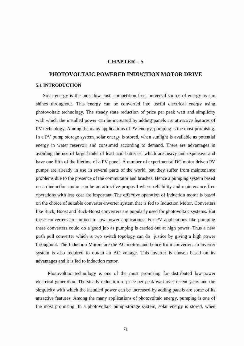
71
CHAPTER – 5
PHOTOVOLTAIC POWERED INDUCTION MOTOR DRIVE
5.1 INTRODUCTION
Solar energy is the most low cost, competition free, universal source of energy as sun
shines throughout. This energy can be converted into useful electrical energy using
photovoltaic technology. The steady state reduction of price per peak watt and simplicity
with which the installed power can be increased by adding panels are attractive features of
PV technology. Among the many applications of PV energy, pumping is the most promising.
In a PV pump storage system, solar energy is stored, when sunlight is available as potential
energy in water reservoir and consumed according to demand. There are advantages in
avoiding the use of large banks of lead acid batteries, which are heavy and expensive and
have one fifth of the lifetime of a PV panel. A number of experimental DC motor driven PV
pumps are already in use in several parts of the world, but they suffer from maintenance
problems due to the presence of the commutator and brushes. Hence a pumping system based
on an induction motor can be an attractive proposal where reliability and maintenance-free
operations with less cost are important. The effective operation of Induction motor is based
on the choice of suitable converter-inverter system that is fed to Induction Motor. Converters
like Buck, Boost and Buck-Boost converters are popularly used for photovoltaic systems. But
these converters are limited to low power applications. For PV applications like pumping
these converters could do a good job as pumping is carried out at high power. Thus a new
push pull converter which is two switch topology can do justice by giving a high power
throughout. The Induction Motors are the AC motors and hence from converter, an inverter
system is also required to obtain an AC voltage. This inverter is chosen based on its
advantages and it is fed to induction motor.
Photovoltaic technology is one of the most promising for distributed low-power
electrical generation. The steady reduction of price per peak watt over recent years and the
simplicity with which the installed power can be increased by adding panels are some of its
attractive features. Among the many applications of photovoltaic energy, pumping is one of
the most promising. In a photovoltaic pump-storage system, solar energy is stored, when

72
sunlight is available, as potential energy in a water reservoir and then consumed according to
demand. There are advantages in avoiding the use of large banks of lead-acid batteries, which
are heavy and expensive and have one-fifth of the lifetime of a photovoltaic panel. It is
important, however, that the absence of batteries does not compromise the efficiency of the
end-to-end power conversion chain, from panels to mechanical pump. Photovoltaic panels
require specific control techniques to ensure operation at their maximum power point (MPP).
Impedance matching issues mean that photovoltaic arrays may operate more or less
efficiently, depending on their series/parallel configuration.
5.1.1 PHOTOVOLTAIC TECHNOLOGY
Converting the sun’s radiation directly into electricity is done by solar cells. These
cells are made of semiconducting materials similar to those used in computer chips. When
sunlight is absorbed by these materials, the solar energy knocks electrons loose from their
atoms, allowing the electrons to flow through the material to produce electricity. This process
of converting light (photons) to electricity (voltage) is called the photovoltaic effect.
Photovoltaics (PV) are thus the field of technology and research related to the application of
solar cells that convert sunlight directly into electricity.
Solar cells, which were originally developed for space applications in the 1950s, are
used in consumer products such as calculators or watches, mounted on roofs of houses or
assembled into large power stations. Today, the majority of photovoltaic modules are used
for grid-connected power generation, but a smaller market for off-grid power is growing in
remote areas and undeveloping countries.
Given the enormous potential of solar energy, photovoltaics may well become a major
source of clean electricity in the future. However, for this to happen, the electricity
generation costs for PV systems need to be reduced and the efficiency of converting sunlight
into electricity needs to increase.
5.2 HOTOVOLTAIC SYSTEM
A photovoltaic system (or PV system) is a system which uses one or more solar panels to
convert sunlight into electricity. It consists of multiple components, including the

73
photovoltaic modules, mechanical and electrical connections and mountings and means of
regulating and modifying the electrical output.
5.2.1 PHOTOVOLTAIC ARRAYS
Due to the low voltage of an individual solar cell typically 0.5V, several cells are wired in
series in the manufacture of a "laminate". The laminate is assembled into a protective
weatherproof enclosure, thus making a photovoltaic module or solar panel. These solar
panels are linked together to form photovoltaic Arrays as shown in Figure5.1.
Figure 5.1 PV array
5.2.2 SERIES CONNECTION OF PV PANELS
The panels are connected in series as shown in Figure5.2. The current through the
cell is constant and the voltage across the cell adds up and the I-V characteristics are shown
in Figure
Figure5.2 Series connection of PV panels
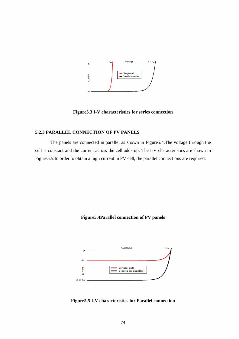
74
Figure5.3 I-V characteristics for series connection
5.2.3 PARALLEL CONNECTION OF PV PANELS
The panels are connected in parallel as shown in Figure5.4.The voltage through the
cell is constant and the current across the cell adds up. The I-V characteristics are shown in
Figure5.5.In order to obtain a high current in PV cell, the parallel connections are required.
Figure5.4Parallel connection of PV panels
Figure5.5 I-V characteristics for Parallel connection

75
5.2.4 WORKING PRINCEPLE OF PV CELL
When photons of light strike the material, however, some normally non-mobile
electrons in the material absorb the photons, and become mobile by virtue of their increased
energy. This creates new holes too - which are just the vacancies created by the newly
created mobile electrons. Because of the "built in" electric field, the new mobile electrons in
the n-material cannot cross over into the p-material. In fact, if they are created near or in the
junction where the electric field exists, they are pushed by the field towards the upper surface
of the n-material. If a wire is connected from the n-material to the p-material, however, they
can flow through the wire, and deliver their energy to a load.
On the other hand, the holes created in the n-material, which are positively charged,
are pushed over into the p-material. In fact, what is really happening here is that an electron
from the p-material, which was also made mobile by the adsorption of a photon, is pushed by
the electric field across the junction and into the n-material to fill the newly created hole.
This completes the circuit as the electrons flows in all the ways around the circuit, dropping
the energy they acquired from photons at a load as shown in Figure5.6.
Figure5.6 PV Cell

76
5.2.5 EQUIVALENT OF PV CELL
The equivalent circuit describes the static behavior of the solar cell. It has a current
source, P-N junction diode, a shunt resistor ( Rsh) and a series resistor (Rse). The practical
and an ideal solar cell is shown in Figure5.7.
Figure5.7: PV equivalent circuit
5.2.6 ADVANTAGES OF PV SOURCE
The following are the outstanding advantages
There are no need for fuel as the, Inexhaustible sunlight is used as the source of electrical
energy.
Clean energy since there is no emission of environmental pollutants, such as NOx and
CO2.
No need for troublesome operations because the system operation is automatic.
Simple system configuration, easy maintenance.
5.2.7 BLOCK DIAGRAM OF PHOTOVOLTAIC PUMPING SYSTEM
Among the many applications of photovoltaic energy, pumping is one of the most
promising. In PV pump storage system, solar energy is stored, when sunlight is available as
potential energy in a water reservoir and is consumed according to the demand. There are
advantages in avoiding the use of large banks of lead acid batteries, which are heavy and
expensive and have one fifth of the lifetime of PV panel.
77
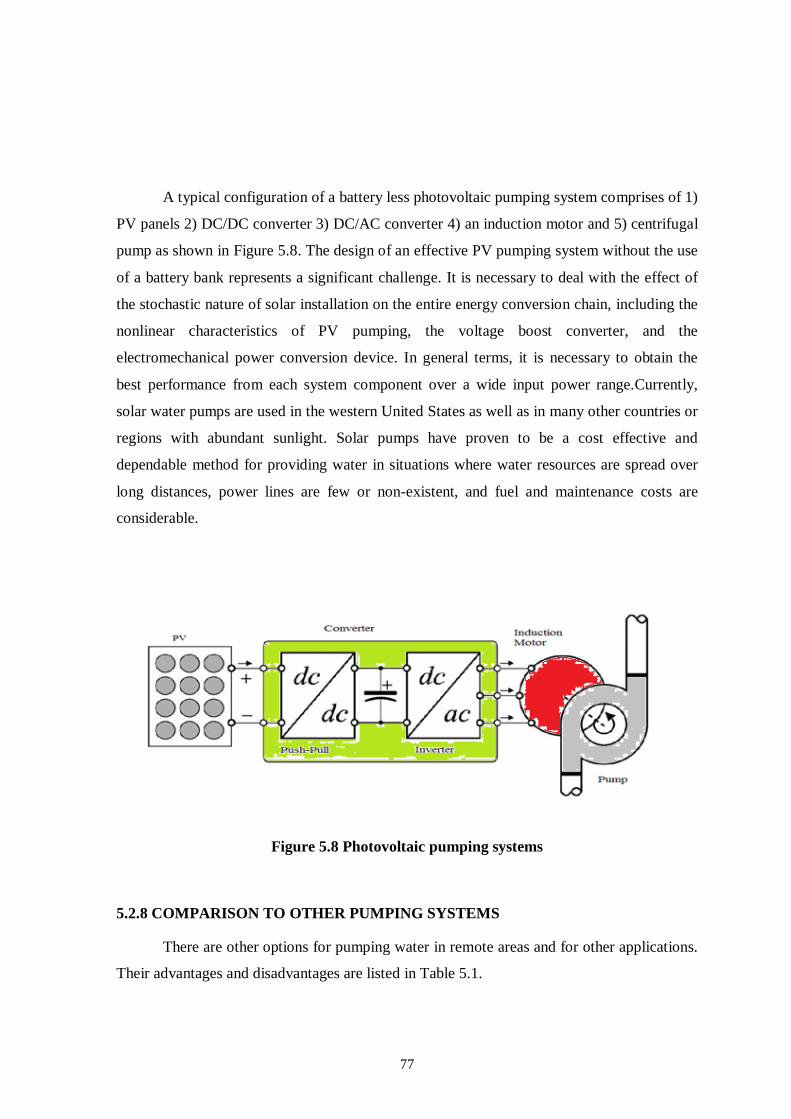
A typical configuration of a battery less photovoltaic pumping system comprises of 1)
PV panels 2) DC/DC converter 3) DC/AC converter 4) an induction motor and 5) centrifugal
pump as shown in Figure 5.8. The design of an effective PV pumping system without the use
of a battery bank represents a significant challenge. It is necessary to deal with the effect of
the stochastic nature of solar installation on the entire energy conversion chain, including the
nonlinear characteristics of PV pumping, the voltage boost converter, and the
electromechanical power conversion device. In general terms, it is necessary to obtain the
best performance from each system component over a wide input power range.Currently,
solar water pumps are used in the western United States as well as in many other countries or
regions with abundant sunlight. Solar pumps have proven to be a cost effective and
dependable method for providing water in situations where water resources are spread over
long distances, power lines are few or non-existent, and fuel and maintenance costs are
considerable.
Figure 5.8 Photovoltaic pumping systems
5.2.8 COMPARISON TO OTHER PUMPING SYSTEMS
There are other options for pumping water in remote areas and for other applications.
Their advantages and disadvantages are listed in Table 5.1.

78
Table 5.1 Comparison of PV and other Pumping system
Pump Type Advantages Disadvantages
Solar Low maintenance
No fuel costs or spills
Easy to install
Simple and reliable
Unattended operation
System can be made to be mobile
Potentially high initial cost
Lower output in cloudy weather
Must have good sun exposure between 9AM to 3PM
Diesel or Gas Moderate capital costs
Can be portable
Extensive experience available
Easy to install
Needs maintenance and replacement
Maintenance often inadequate reducing life
Fuel often expensive and supply intermittent
Noise, dirt and fume problem
Site visits necessary
Windmill Potentially long-lasting
Works well in windy site
High maintenance and costly repair
Difficult to find parts
Seasonal disadvantageous
Need special tool for installation
No wind No power
There are more than 10,000 solar powered water pumps in use in the world today.
They are widely used on farms and outback stations in Australia to supply water to livestock.
In developing countries they are used extensively to pump water from wells and rivers to
villages for domestic consumption and irrigation of crops. A typical PV-powered pumping
system consists of a PV array that powers an electric motor, which drives a pump. The water
is often pumped from the ground or stream into a storage tank that provides a gravity feed.
No energy storage is needed for these systems. PV powered pumping systems are widely

79
available from agricultural equipment suppliers and they are a cost-effective alternative to
agricultural wind turbines for remote area water supply.
Photovoltaic pumping systems are used to pump water for livestock, plants or
humans. Since the need for water is more on hot sunny days the technology is an obvious
choice for this application. Pumping water using PV technology is simple, reliable, and
requires almost no maintenance. Agricultural watering needs are usually more during sunnier
periods when more water can be pumped with a solar system. PV powered pumping systems
are excellent for small to medium scale pumping and there are thousands of agricultural PV
water pumping systems in the field today throughout the world. PV powered water pumping
systems are similar to any other pumping system, only the power source is solar energy. PV
pumping systems have, as a minimum, a PV array, a motor, and a pump. PV water pumping
arrays are fixed, mounted or sometimes placed on passive trackers (which use no motors) to
increase pumping time and volume. AC and DC motors with centrifugal or displacement
pumps are used with PV pumping systems. Assessment of the economic viability of PV
pumping systems by IEA in comparison to diesel pumping systems indicate that, although
the high investment cost of PV pumping systems is a major factor to slowed expansion of the
market. But still the life cycle cost of PV is often less than diesel or petrol-powered pumps
which are a challenging factor
5.2.9 INTRODUCTION TO PUSH PULL CONVERTER
Push-Pull type DC - DC converter is suitable to boost up the voltage from low to high
voltage. This converter may be used in conjunction with a high frequency transformer to
boost the output voltage with the advantage of providing isolation between the input and
output stage. In this project a simple two switch push pull converter topology is used, which
will step up a 12V DC voltage supply to the required output voltage. A 12Vsupply is used as
the input supply. The high frequency transformer is known as the push pull transformer.
This push pull transformer is usually the preferred choice in high power switching
transformer applications exceeding one kilowatt. Power ratings for push pull transformer can
vary from a fraction of a Watt to Kilowatt.

80
5.2.10 CIRCUIT DESCRIPTION OF PUSH PULL CONVERTER
The circuit diagram of the step up dc/dc converter is shown in Figure 5.9
Figure 5.9 Push-Pull converter
With reference to the figure 5.11, when Q1 switch is on, current flows through the
‘upper’ half of ‘n’ primary and the magnetic field in ‘n’ expands. The expanding magnetic
field in ‘n’ induces a voltage across ‘n’ secondary, the polarity is such that D1D2 is forward
biased and D3D4 is reverse biased. D1D2 conducts and charges the output capacitor C.
When Q1 turns off, the magnetic field in ‘n’ collapses, and after a period of dead time,
Q2 conducts, current flows through the ‘lower’ half of ‘n’ primary and the magnetic field in
‘n’expands. Now the direction of the magnetic flux is opposite to that produced when Q1 is
conducted. The expanding magnetic field induces a voltage across n’s secondary, the polarity
is such that D3D4 is forward biased and D1D2 is reverse biased. D3D4conducts and charges
the output capacitor C. After a period of dead time, Q1 conducts and the cycle repeats.
There are two important considerations with the push pull converter:
Both transistors must not conduct together, as this would effectively short circuit the
supply, which means that the conduction time of each transistor must not exceed half of
the total period for one complete cycle, otherwise conduction will overlap.
The magnetic behavior of the circuit must be uniform, otherwise the transformer may
saturate, and this would cause destruction of Q1 and Q2. This requires that the individual

81
conduction times of Q1 and Q2 be exactly equal and the two halves of the centre-tapped
transformer primary be magnetically identical.
5.2.11 SELECTION OF MOTOR DRIVE SYSTEM
The selection criteria of electrical motors depend on the cost and compatibility at
which the motors work. In this project the induction motor is chosen, as the AC motors are
more advantageous than DC motors. The comparison of electrical motors and drawbacks
with DC motors a listed in the Table 5.2.The most common and simple industrial motor is the
three phase AC induction motor. The various aspects at which the three phase AC induction
motor was selected is also listed.
Table 5.2 Comparison of DC and AC drive system
DC MOTORS AC MOTORS
The commutator and brushes makes the motor bulky, costly and heavy.
Costly
It requires frequent maintenance.
Requires battery or inverter.
Not bulky and heavy.
Expensive
Less maintenance
They can be used in all locations, as the supply is AC.
Simple Design
The design of the AC motor is simple because, it has simply a series of three
windings in the exterior (stator) section with a simple rotating section (rotor). The changing
field caused by 50 or 60 Hertz AC line voltage causes the rotor to rotate around the axis of
the motor.
The speed of the AC motor depends only on three variables:

82
The fixed number of winding sets (known as poles) built into the motor, which
determines the motor’s base speed.
The frequency of the AC line voltage. Variable speed drives change this frequency to
change the speed of the motor.
The amount of torque loading on the motor, which causes slip.
Low Cost
The AC motor has the advantage of being the lowest cost motor for applications. This
is due to the simple design of the motor. For this reason, AC motors are overwhelmingly
preferred for fixed speed applications in industrial applications and for commercial and
domestic applications where AC line power can be easily attached. Over 90% of all motors
are AC induction motors. They are found in air conditioners, washers, dryers, industrial
machinery, fans, blowers, vacuum cleaners, and many, many other applications.
Reliable Operation
The simple design of the AC motor results in extremely reliable, low maintenance
operation. Unlike the DC motor, there are no brushes to replace. If run in the appropriate
environment for its enclosure, the AC motor needs new bearings after several years of
operation. If the application is well designed, an AC motor may not need new bearings for
more than a decade.
5.2.12 SIMULINK MODEL OF PUSH PULL CONVERTER
The push-pull converter has a push-pull inverter with transformer and Diode Bridge.
Hence the push-pull inverter is simulated first and then the diode bridge is coupled to push-
pull inverter.
Simulation of Push-Pull Inverter
The simulink model of push-pull inverter is shown in Figure 5.10. The MOSFETS, 1
and 2 do the inverting operation. MOSFETs are used as switches due to its high frequency
operation and because of their fast switching speed; the switching losses can be small. Their
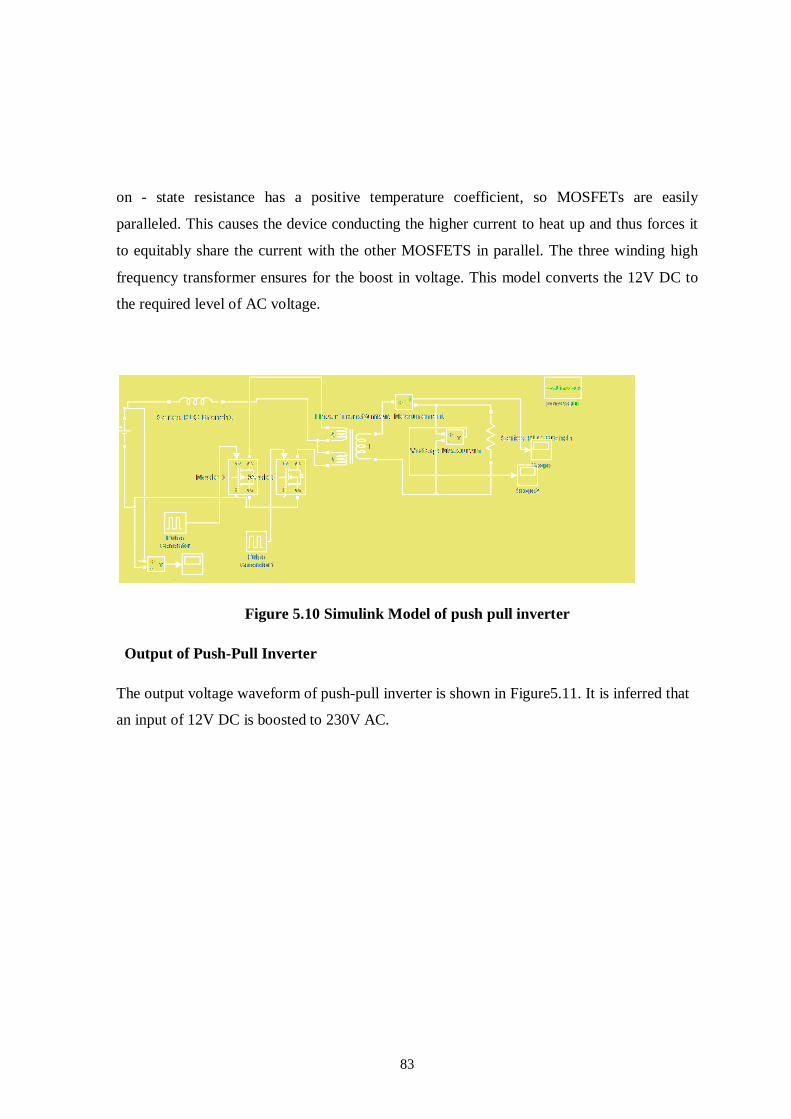
83
on - state resistance has a positive temperature coefficient, so MOSFETs are easily
paralleled. This causes the device conducting the higher current to heat up and thus forces it
to equitably share the current with the other MOSFETS in parallel. The three winding high
frequency transformer ensures for the boost in voltage. This model converts the 12V DC to
the required level of AC voltage.
Figure 5.10 Simulink Model of push pull inverter
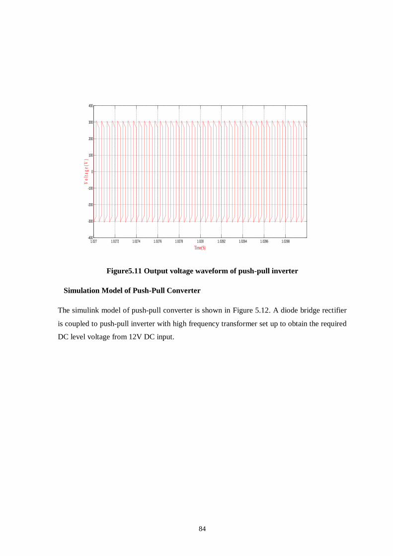
Output of Push-Pull Inverter
The output voltage waveform of push-pull inverter is shown in Figure5.11. It is inferred that
an input of 12V DC is boosted to 230V AC.
84
Figure5.11 Output voltage waveform of push-pull inverter
Simulation Model of Push-Pull Converter
The simulink model of push-pull converter is shown in Figure 5.12. A diode bridge rectifier
is coupled to push-pull inverter with high frequency transformer set up to obtain the required
DC level voltage from 12V DC input.
1.027 1.0272 1.0274 1.0276 1.0278 1.028 1.0282 1.0284 1.0286 1.0288-400
-300
-200
-100
0
100
200
300
400
Time(S)
Vol
tage
(V)

85
Figure 5.12 Simulink Model of push pull converter
Output of Push-Pull Converter
The output voltage waveform of push-pull converter is shown in Figure5.13. It is
observed that the 230V AC obtained at the output of high frequency transformer is rectified
using diode bridge rectifier to approximately 400V DC.
Figure 5.13 Output Voltage Waveform of push-pull converter
0 1 2 3 4 5 6 7 8 9 10-50
0
50
100
150
200
250
300
350
400
Time(S)
Vol
tage
(V)

86
Power measurement for Push-pull converter
The converters like buck, boost, buck-boost and cuk converters employs single
transistor. Due to the current handling limitation of single transistor, the output power of
these converters is small, typically tens of watts. In addition, there is no isolation between the
input and output voltage, which is highly desirable criterion in most applications. The above
drawbacks are overcome by using push-pull converters. The simulink model for power
measurement of push pull converter is shown in Figure 5.14.
Figure 5.14 Simulink model for measurement of power in push-pull converter
It is seen that 51.48W of power is measured from the push-pull converter.
5.3 BOOST CONVERTER
The DC/DC converter boosts the photovoltaic panel voltage up to the value required
to drive an off-the-shelf induction motor. This is needed to accommodate the requirement
that relatively few photovoltaic panels be connected in series. The push–pull converter
topology ensures galvanic isolation between input and output voltages, as well as provides
the required voltage gain. The basic circuit diagram of the step-up converter is shown in
Fig.2. The operation of this converter relies on the time intervals in which power switches qa
and qb conduct. Fig. 3 shows a typical switching pattern for one period T. In this figure, D
denotes the duty cycle defined by
D = Ton/T (5.1)
87
Where Ton corresponds to the total time interval that both Switches conduct (Ton=DT). The
output voltage (E) depends on the input voltage (V), the duty cycle (D), and the high-
frequency transformer turns ratio (n), i.e.,
E = [n/1 – D] V (5.2)
When designing a push–pull converter, it is convenient to select the transformer turns
ratio n such that duty cycle D does not vary in a wide range. At the same time, high values
for n should be avoided to ensure that the pulse width modulation (PWM) voltage inverter
operates with low modulation index.
A. Push–Pull Gain
Acting as an adjustable-ratio DC transformer, the DC/DC converter allows
impedance matching between the panels and the motor drives the centrifugal pump. The
choice of converter gain is most easily explained using an example. Consider the following:
1) The electrical load is a 230 V/50 Hz 0.5 hp induction motor; 2) The photovoltaic array is
composed of ten 130 Wp panels arranged in a 2 (series) × 5 (parallel) layout; and 3) The
losses are neglected. Fig. 4 shows the mechanical torque of the motor, the pump
characteristic (upper plot), and the motor efficiency (lower plot) curves as functions of rotor
(mechanical) speed. Assuming that the motor operates at a constant volt/hertz ratio, the
operating points are determined by the intersection of the mechanical torque and load (pump)
characteristic curves. Based on the power level demanded by the load, it is possible to
determine the numerical values of the input and output push–pull voltages. For each
operating point, therefore, it is possible to recover values for the motor line voltage to
determine the minimum required DC-bus voltage, which corresponds to the push–pull output
voltage. The push–pull input voltage is the MPPT panel array voltage. Thus given the motor
output power, it is possible to numerically find the push–pull input voltage.
5.4 SIMULATION RESUILTS
Push Pull inverter system alone is simulated as shown in figure 5.15. The output of
the Push Pull inverter is stepped up using step up transformer. DC input voltage is shown in
figure 5.16. Drive pulses for M1 and M2 are shown in figure 5.17. It is 24 volts. This voltage
is stepped up to 220 volts as shown in figure 5.18.

88
Push Pull inverter based drive system is shown in figure5.19. The transformer output is
shown in figure 5.20. The rectifier output voltage is as shown in figure5.21. The driving
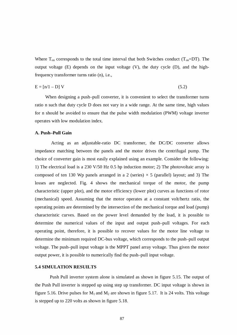
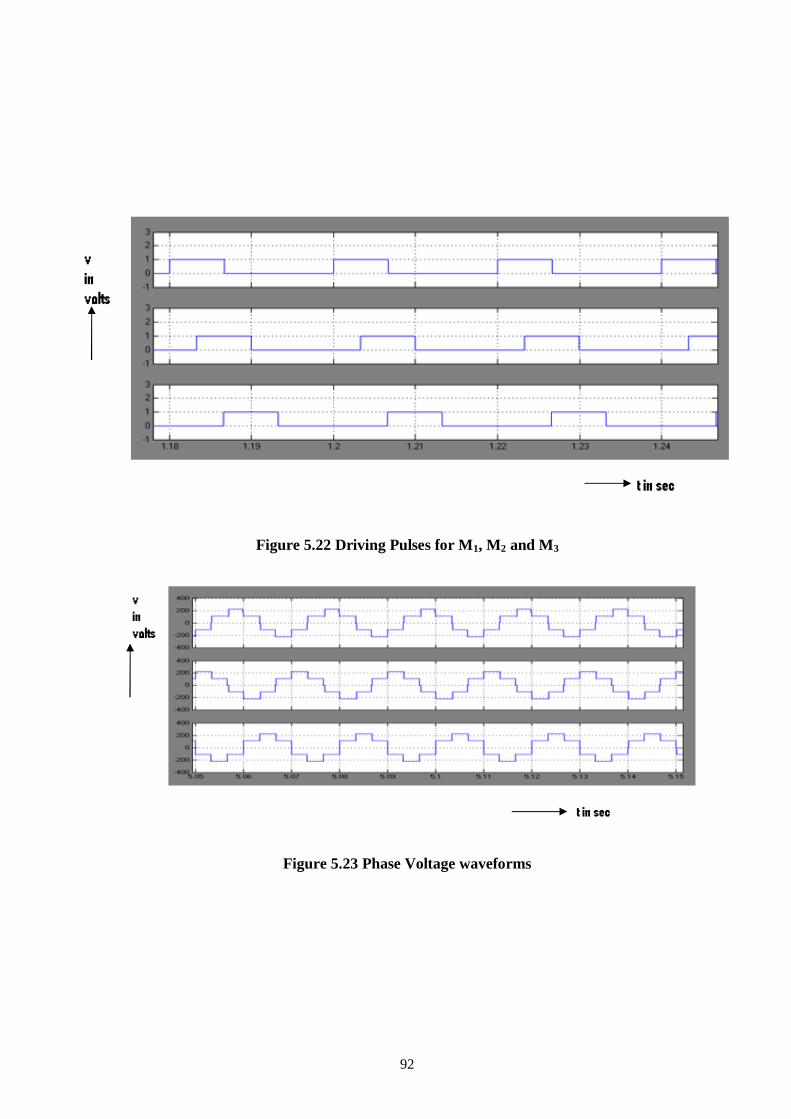
pulses for M1, M2 and M3 are shown in figure 5.22. The phase voltage applied to the motor is
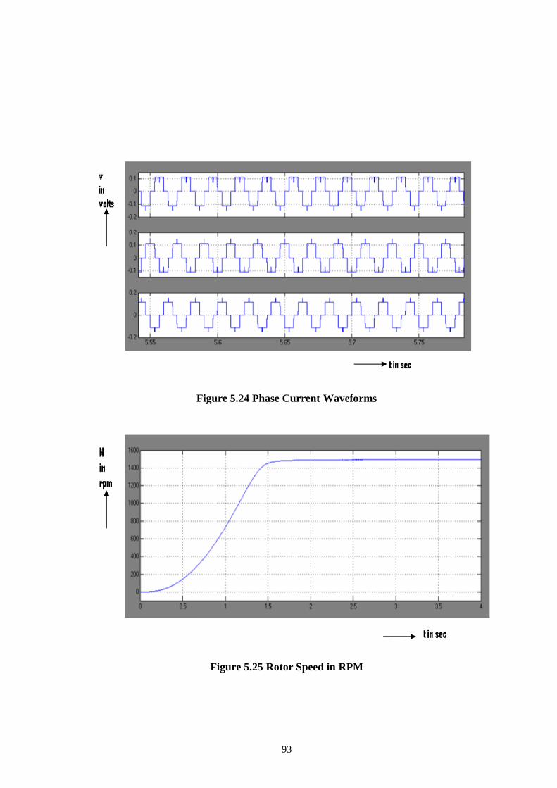
shown in figure 5.23. The voltages are displaced by 120 degrees. The phase currents are
shown in figure 5.24. The speed response is shown in figure 5.25. The speed increases and
settles at 1460 rpm.
Figure 5.15 Push Pull DC to DC Converter

89
Figure 5.16 DC input voltage
Figure 5.17 Driving pulses for M1 and M2

90
Figure 5.18 Transformer primary voltages
Figure 5.19 Three Phase Inverter with Motor load

91
Figure 5.20 Transformer secondary voltage
Figure 5.21 Rectifier output voltage
92
Figure 5.22 Driving Pulses for M1, M2 and M3
Figure 5.23 Phase Voltage waveforms
93
Figure 5.24 Phase Current Waveforms
Figure 5.25 Rotor Speed in RPM

94
5.5 EXPERIMENTAL RESUILTS
The hardware of PV Powered Induction motor drive is fabricated and tested in the
laboratory. The experimental set up of the hardware is shown in figure 5.26. This consists of
inverter board, Push Pull board and control board. The hardware of control circuits alone is
shown in figure 5.27. The hardware of Push Pull Converter is shown in figure 5.28.The Input
voltage waveform of transformer is shown in figure5.29. This consists of two MOSFETS.
The switching pulses for the Push Pull Converter are shown in figure 5.30. The pulses are
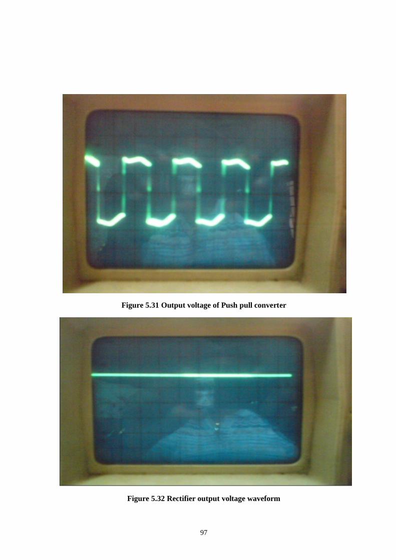
displaced by 180 degrees. The output of the Push Pull Converter is shown in figure 5.31. DC
output of the rectifier is shown in figure 5.32. The phase voltage of the three phase inverter is
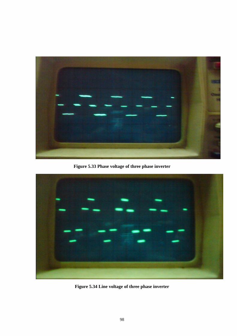
shown in figure 5.33. The line voltage of three phase inverter is shown in figure 5.34.
Figure 5.26 Hardware circuit

95
Figure 5.27 Control circuit
Figure 5.28 Push pull converter

96
Figure 5.29 Input voltage waveform
Figure 5.30 switching pulse for push pull converter
97
Figure 5.31 Output voltage of Push pull converter
Figure 5.32 Rectifier output voltage waveform
98
Figure 5.33 Phase voltage of three phase inverter
Figure 5.34 Line voltage of three phase inverter

99
5.6 CONCLUSION
This work has evaluated the strategy for utilization of PV Cells for induction motor
pumping. The electricity bill gets reduced since solar energy is utilized for agriculture
pumping. The Photo Voltaic powered three phase induction motor drive system is
successfully designed, modelled and simulated using matlab simulink. The concept of Photo
Voltaic pumping is proposed. The simulation and experimental results of three phase
induction motor for Photo Voltaic pumping are presented. The simulation results are in line
with the theoretical results. The scope of this work is the simulation and implementation of
three phase PV Powered Induction motor drive system. The experimental results are similar
to the simulation results.