Embed Size (px)
Citation preview
Chapter 5 (part2) Electric Fields In this chapter we will introduce the concept of an electric field. As long as charges are stationary Coulomb’s law described adequately the forces among charges. If the charges are not stationary we must use an alternative approach by introducing the electric field (symbol ). In connection with the electric field, the following topics will be covered:
-Calculate the electric field generated by a point charge. -Using the principle of superposition determine the electric field created by a collection of point charges as well as continuous charge distributions. -Once the electric field at a point P is known we will be calculate the electric force on any charge placed at P -Define the notion of an “electric dipole”. Determine the net force , the net torque, exerted on an electric dipole by a uniform electric field, as well as the dipole potential energy.
E!
1
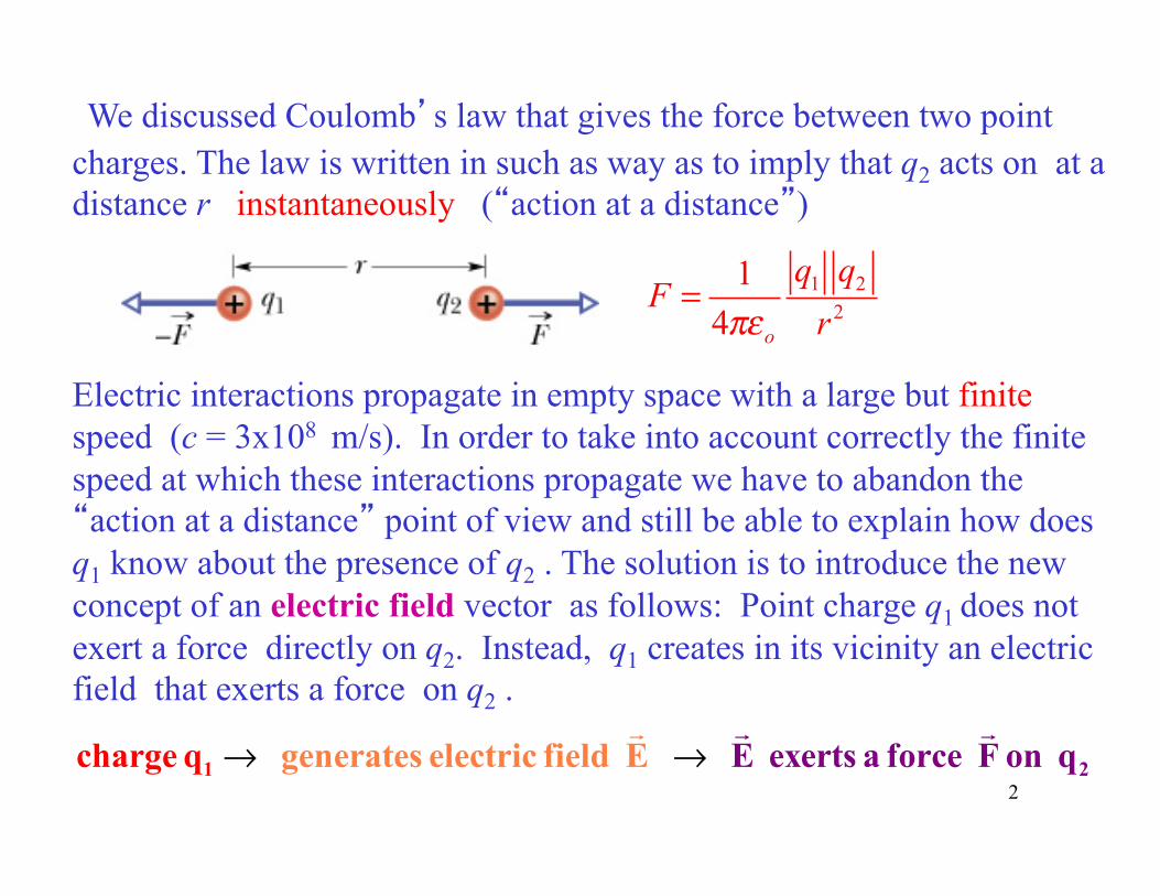
We discussed Coulomb’s law that gives the force between two point charges. The law is written in such as way as to imply that q2 acts on at a distance r instantaneously (“action at a distance”)
Electric interactions propagate in empty space with a large but finite speed (c = 3x10⁸ m/s). In order to take into account correctly the finite speed at which these interactions propagate we have to abandon the “action at a distance” point of view and still be able to explain how does q1 know about the presence of q2 . The solution is to introduce the new concept of an electric field vector as follows: Point charge q1 does not exert a force directly on q2. Instead, q1 creates in its vicinity an electric field that exerts a force on q2 .
1 22
1 4 o
q qF
rπε=
→ →1 2generates electric field E exerts aE f orce char ge F qq on ! !!
2
q
+qo
r
P
E!
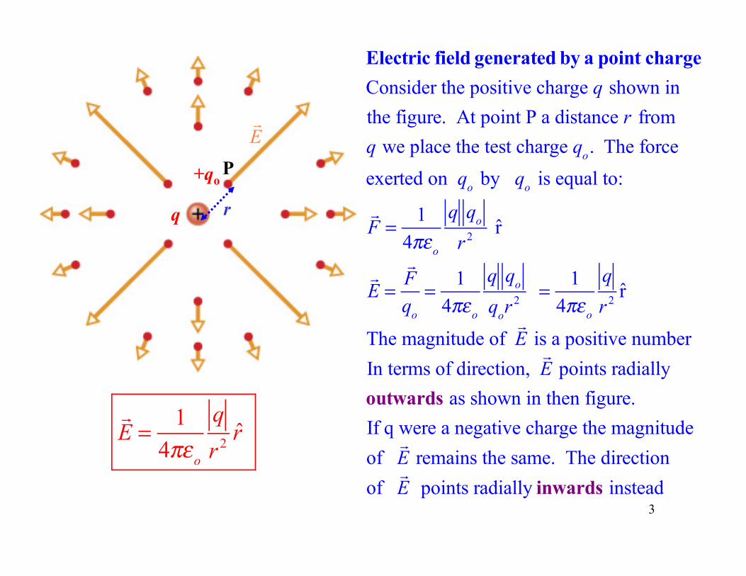
Electric field generated by a point chargeConsider the positive charge q shown inthe figure. At point P a distance r from q we place the test charge qo. The force
exerted on qo by qo is equal to:
!F = 1
4πεo
q qo
r 2 r
!E =
!Fqo
= 14πεo
q qo
qor2 = 1
4πεo
q
r 2 r
The magnitude of !E is a positive number
In terms of direction, !E points radially
outwards as shown in then figure.If q were a negative charge the magnitudeof !E remains the same. The direction
of !E points radially inwards instead
3
!E = 1
4πεo
q
r 2 r
4
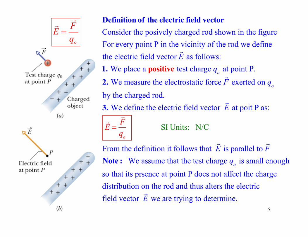
Definition of the electric field vectorConsider the posively charged rod shown in the figureFor every point P in the vicinity of the rod we definethe electric field vector
!E as follows:
1. We place a positive test charge qo at point P.
2. We measure the electrostatic force !F exerted on qo
by the charged rod.3. We define the electric field vector
!E at poit P as:
!E =
!Fqo
SI Units: N/C
From the definition it follows that !E is parallel to
!F
Note : We assume that the test charge qo is small enough
so that its prsence at point P does not affect the chargedistribution on the rod and thus alters the electric field vector
!E we are trying to determine.
o
FE
q=!
!
5
6
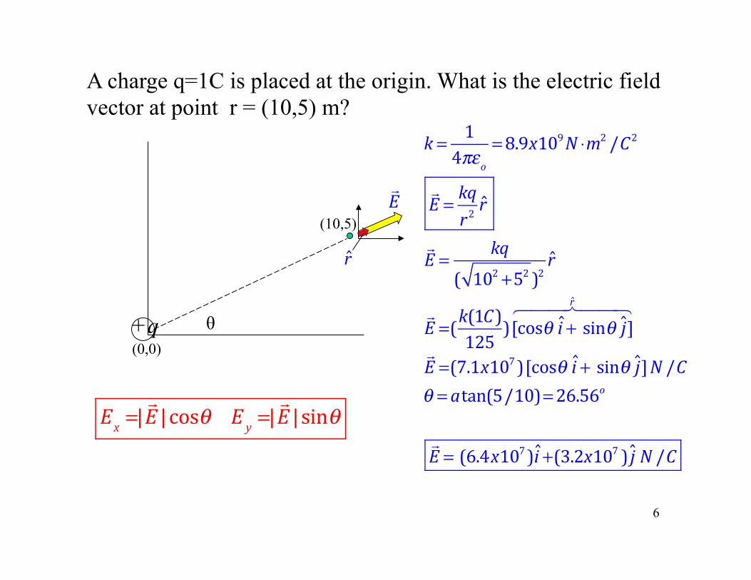
+q
A charge q=1C is placed at the origin. What is the electric field vector at point r = (10,5) m?
(10,5)
(0,0)
k = 14πεo
=8.9x10⁹N ⋅m2 /C2
!E = kq
r2r
!E = kq
( 102 +52 )2r
!E =(k(1C)125 )[cosθ i + sinθ j]
r" #$$ %$$
!E =(7.1x10⁷)[cosθ i + sinθ j]N /Cθ = atan(5/10)=26.56o
!E = (6.4x10⁷)i +(3.2x10⁷ ) j N /C
θ
r
!E
Ex =|
!E |cosθ Ey =|
!E |sinθ
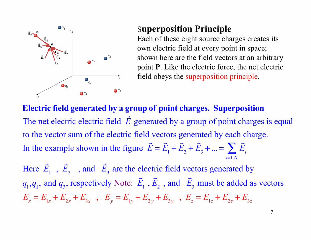
Electric field generated by a group of point charges. SuperpositionThe net electric electric field
!E generated by a group of point charges is equal
to the vector sum of the electric field vectors generated by each charge.In the example shown in the figure
!E =!E1 +
!E2 +
!E3 + ...=
!Ei
i=1,N∑
Here !E1 ,
!E2 , and
!E3 are the electric field vectors generated by
q1,q1, and q3, respectively Note: !E1 , !E2 , and
!E3 must be added as vectors
Ex = E1x + E2x + E3x , Ey = E1y + E2 y + E3y , Ez = E1z + E2z + E3z
7
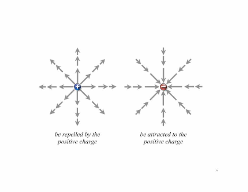
Superposition Principle Each of these eight source charges creates its own electric field at every point in space; shown here are the field vectors at an arbitrary point P. Like the electric force, the net electric field obeys the superposition principle.
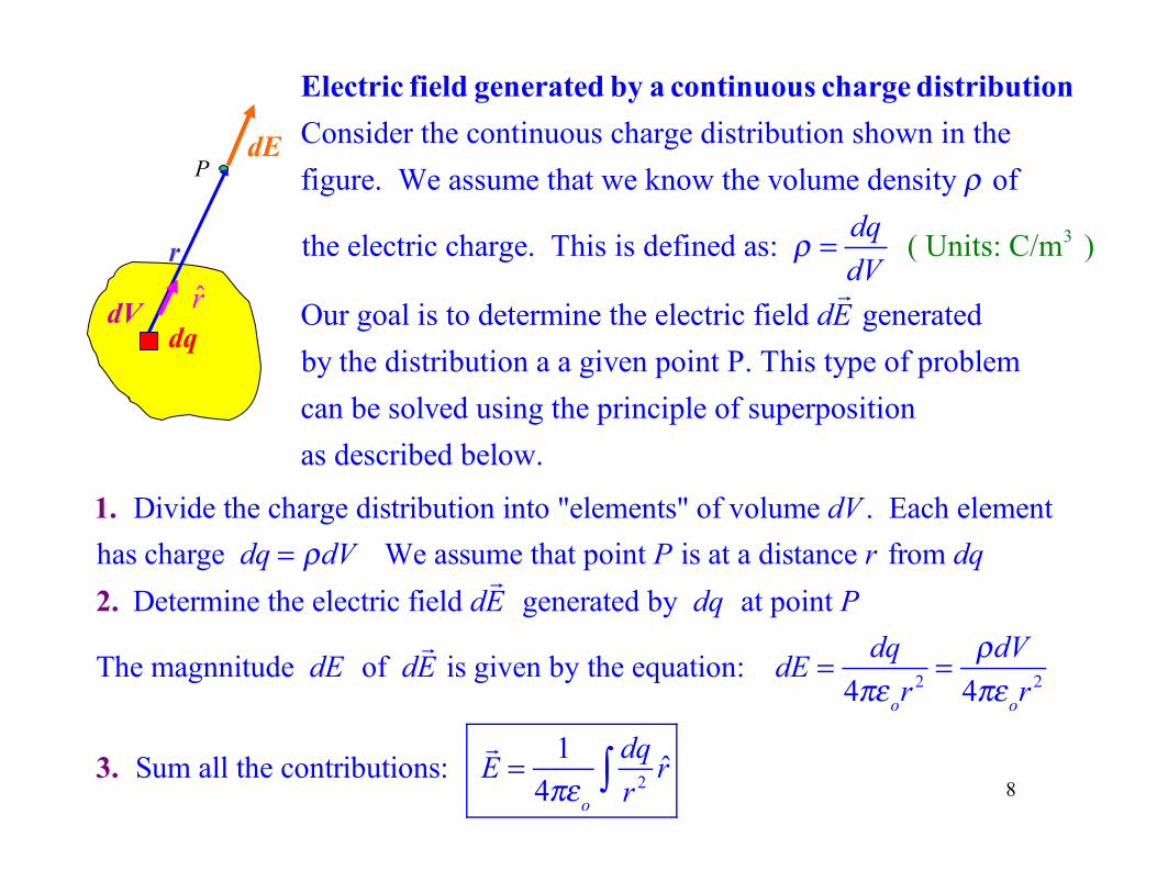
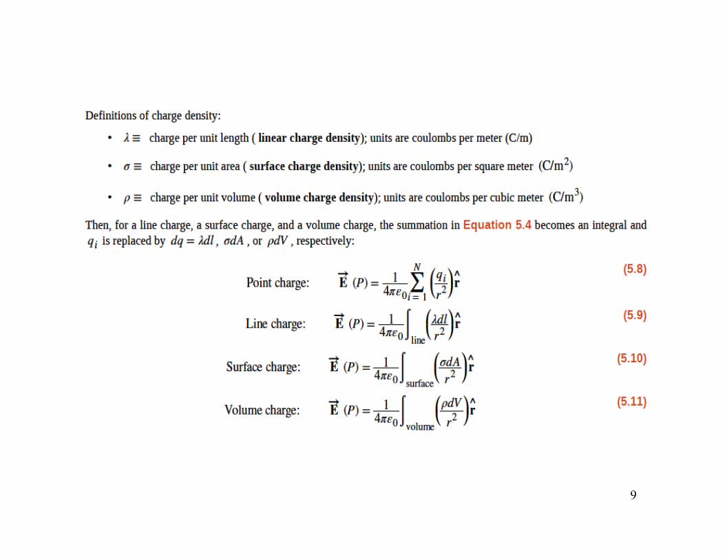
Consider the continuous charge distribution shown in thefigure. We assume that we know the volume density of
the electric charge. This i
ρ
Electric field generated by a continuous charge distribution
3s defined as:
Our goal is to determine the electric field generatedby the distribution a a given point P. This type of problemcan be solved using the
(
principle of sup
Units: C/m
erpo i
)
s
dqdV
dE
ρ =!
tionas described below.
1. Divide the charge distribution into "elements" of volume dV . Each elementhas charge dq = ρdV We assume that point P is at a distance r from dq 2. Determine the electric field d
!E generated by dq at point P
The magnnitude dE of d!E is given by the equation: dE = dq
4πεor2 = ρdV
4πεor2
3. Sum all the contributions: !E = 1
4πεo
dqr 2 r∫
dq
r
dE
dV r
8
P
9
10
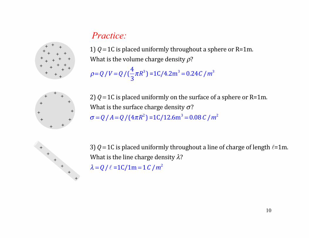
1) Q =1CisplaceduniformlythroughoutasphereorR=1m.Whatisthevolumechargedensityρ?
ρ=Q/V =Q/(43πR3)=1C/4.2m3 =0.24C /m3
2)Q =1CisplaceduniformlyonthesurfaceofasphereorR=1m.Whatisthesurfacechargedensityσ?σ =Q/A=Q/(4πR2)=1C/12.6m3 =0.08C /m2
3)Q =1Cisplaceduniformlythroughoutalineofchargeoflength ℓ=1m.Whatisthelinechargedensityλ?λ =Q/ℓ=1C/1m =1C /m2
+ + +
+ +
+
+
+
+ + +
+
+
+
+ + +
+
+ + +
+ +
+ +
+ +
+ +
+
+ + +
+ +
+ +
+
Practice:
C A
dq
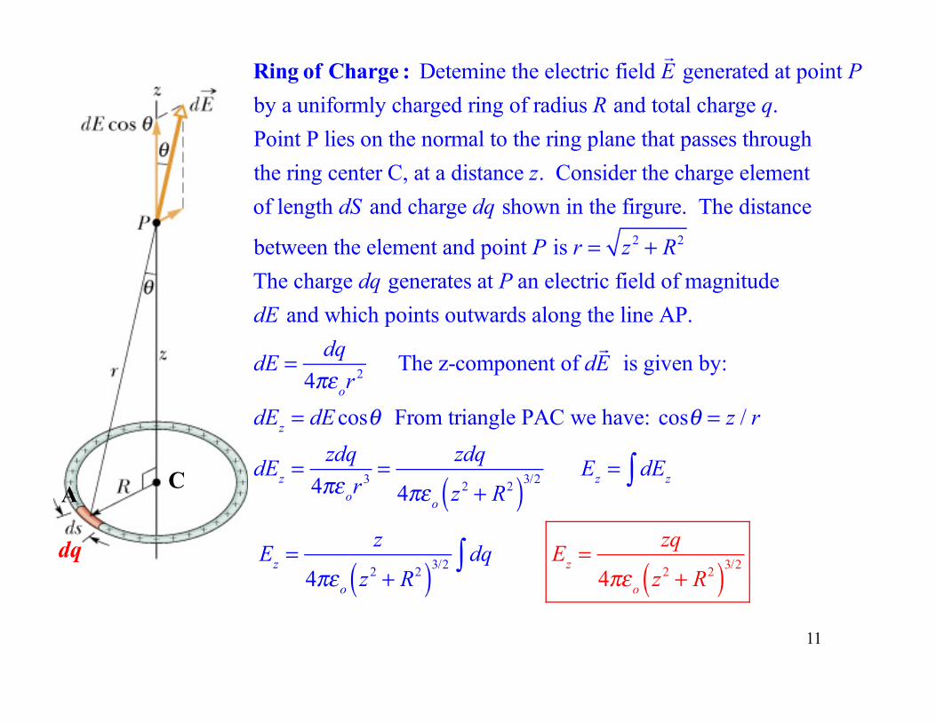
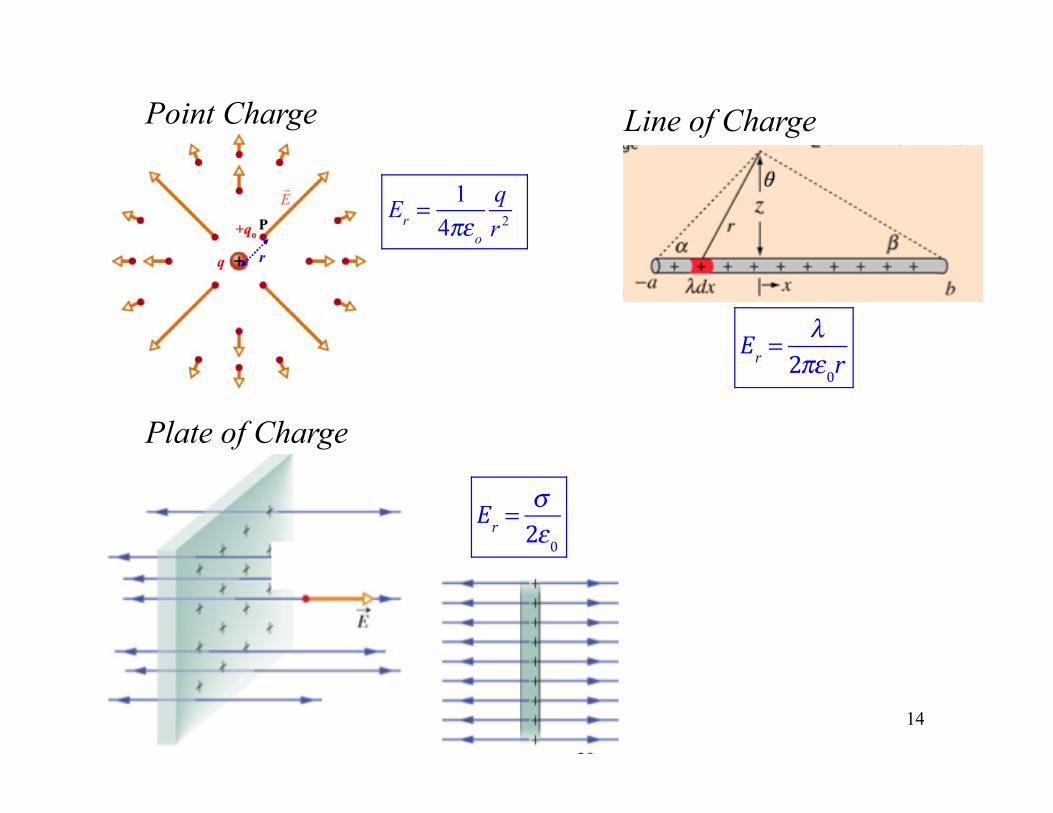
Ring of Charge : Detemine the electric field !E generated at point P
by a uniformly charged ring of radius R and total charge q. Point P lies on the normal to the ring plane that passes throughthe ring center C, at a distance z. Consider the charge elementof length dS and charge dq shown in the firgure. The distance
between the element and point P is r = z2 + R2
The charge dq generates at P an electric field of magnitudedE and which points outwards along the line AP.
dE = dq4πεor
2 The z-component of d!E is given by:
dEz = dE cosθ From triangle PAC we have: cosθ = z / r
dEz =zdq
4πεor3 =
zdq
4πεo z2 + R2( )3/2 Ez = dEz∫
Ez =z
4πεo z2 + R2( )3/2 dq∫ Ez =zq
4πεo z2 + R2( )3/2
11
12
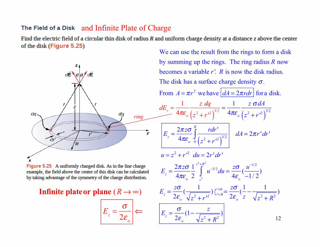
We can use the result from the rings to form a diskby summing up the rings. The ring radius R now becomes a variable r '. R is now the disk radius. The disk has a surface charge density σ .
From A = πr 2 we have dA = 2πrdr fora disk.
dEz =1
4πεo
z dq
z2 + r '2( )3/2 = 14πεo
z σ dA
z2 + r '2( )3/2
Ez =2π zσ4πεo
rdr '
z2 + r '2( )3/20
R
∫ dA = 2πr 'dr '
u = z2 + r '2 du = 2r 'dr '
Ez =2π zσ4πεo
12
u−3/2
z2
z2+R2
∫ du = zσ4εo
(u−1/2
−1/ 2)
Ez =zσ2εo
(1
z2 + r '2) |r '=R
r '=0 = zσ2εo
(1z− 1
z2 + R2)
Ez =σ
2εo
(1− z
z2 + R2)
and Infinite Plate of Charge
Infinite plateor plane (R→∞)
Ez =σ
2εo
⇐
ring
13
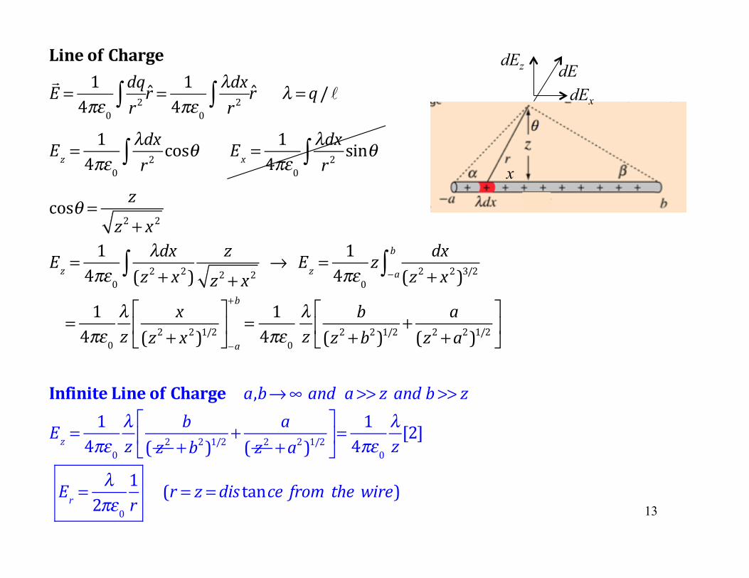
Line of Charge!E = 1
4πε0dqr2∫ r = 1
4πε0λdxr2∫ r λ = q/ℓ
Ez =1
4πε0λdxr2∫ cosθ Ex =
14πε0
λdxr2∫ sinθ
cosθ = z
z2 + x2
Ez =1
4πε0λdx
(z2 + x2)∫z
z2 + x2→ Ez =
14πε0
z dx(z2 + x2)3/2−a
b
∫
= 14πε0
λz
x(z2 + x2)1/2⎡
⎣⎢
⎤
⎦⎥−a
+b
= 14πε0
λz
b(z2 +b2)1/2 +
a(z2 +a2)1/2
⎡
⎣⎢
⎤
⎦⎥
Infinite Line of Charge a,b→∞ and a>> z and b>> z
Ez =1
4πε0λz
b( z2 +b2)1/2 +
a( z2 +a2)1/2
⎡
⎣⎢
⎤
⎦⎥=
14πε0
λz[2]
Er =λ
2πε01r
(r = z = dis tance from the wire)
x
dE dEx
dEz
14
Er =
14πεo
qr 2
Er =
λ2πε0r
Er =
σ2ε0
Plate of Charge
Line of Charge Point Charge
electric field lines P Q
PE!
QE!
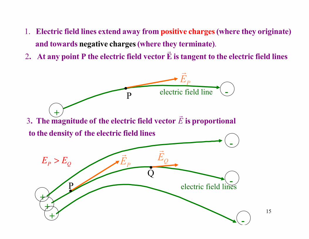
1. Electric field lines extend away from positive charges (where they originate)and towards negative charges (where they terminate).
2. At any point P the electric field vector !E is tangent to the electric field lines
P PE!
electric field line
3. The magnitude of the electric field vector !E is proportional
to the density of the electric field lines
P QE E>
15
+
+++
-
-
-
-

Electric DipoleElectric field lines generated by an electric dipole (a positive and a negative point charge of the same size but of opposite sign)
Same signed dipoleElectric field lines generated by two equal positive point charges.The line move off to find negativecharges at ∞!
16
∞
17
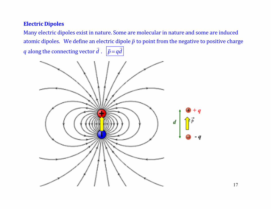
ElectricDipolesManyelectricdipolesexistinnature.Somearemolecularin nature andsomeareinducedatomicdipoles.Wedefineanelectricdipole!ptopointfromthenegativetopositivechargeqalongtheconnectingvector
!d . !p= q
!d
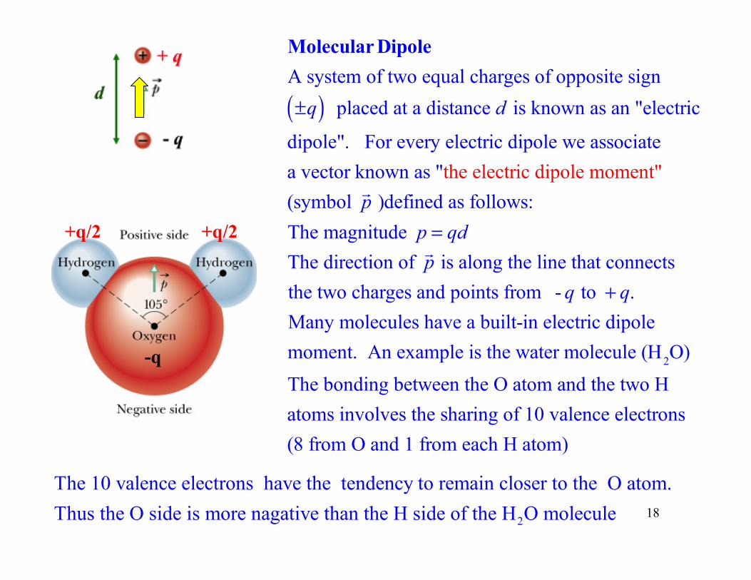
Molecular DipoleA system of two equal charges of opposite sign±q( ) placed at a distance d is known as an "electric
dipole". For every electric dipole we associate a vector known as "the electric dipole moment" (symbol !p )defined as follows:The magnitude p = qdThe direction of !p is along the line that connectsthe two charges and points from - q to + q. Many molecules have a built-in electric dipole moment. An example is the water molecule (H2O)The bonding between the O atom and the two Hatoms involves the sharing of 10 valence electrons(8 from O and 1 from each H atom)
2
The 10 valence electrons have the tendency to remain closer to the O atom.Thus the O side is more nagative than the H side of the H O molecule 18
-q
+q/2 +q/2
19
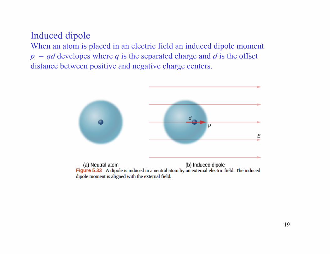
Induced dipole When an atom is placed in an electric field an induced dipole moment p = qd developes where q is the separated charge and d is the offset distance between positive and negative charge centers.
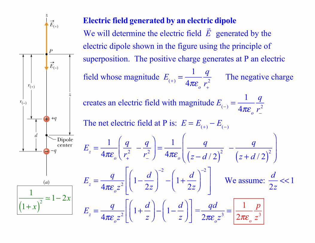
Electric field generated by an electric dipoleWe will determine the electric field
!E generated by the
electric dipole shown in the figure using the principle ofsuperposition. The positive charge generates at P an electric
field whose magnitude E(+ ) =1
4πεo
qr+
2 The negative charge
creates an electric field with magnitude E(− ) =1
4πεo
qr−
2
The net electric field at P is: E = E(+ ) − E(− )
Ez =1
4πεo
qr+
2 − qr−
2
⎛
⎝⎜⎞
⎠⎟= 1
4πεo
q
z − d / 2( )2 − q
z + d / 2( )2
⎛
⎝⎜⎜
⎞
⎠⎟⎟
Ez =q
4πεoz2 1− d2z
⎛⎝⎜
⎞⎠⎟
−2
− 1+ d2z
⎛⎝⎜
⎞⎠⎟
−2⎡
⎣⎢⎢
⎤
⎦⎥⎥
We assume: d2z
<<1
Ez =q
4πεoz2 1+ dz
⎛⎝⎜
⎞⎠⎟− 1− d
z⎛⎝⎜
⎞⎠⎟
⎡
⎣⎢
⎤
⎦⎥ =
qd2πεoz3 =
12πεo
pz3
1
1+ x( )2 ! 1− 2x
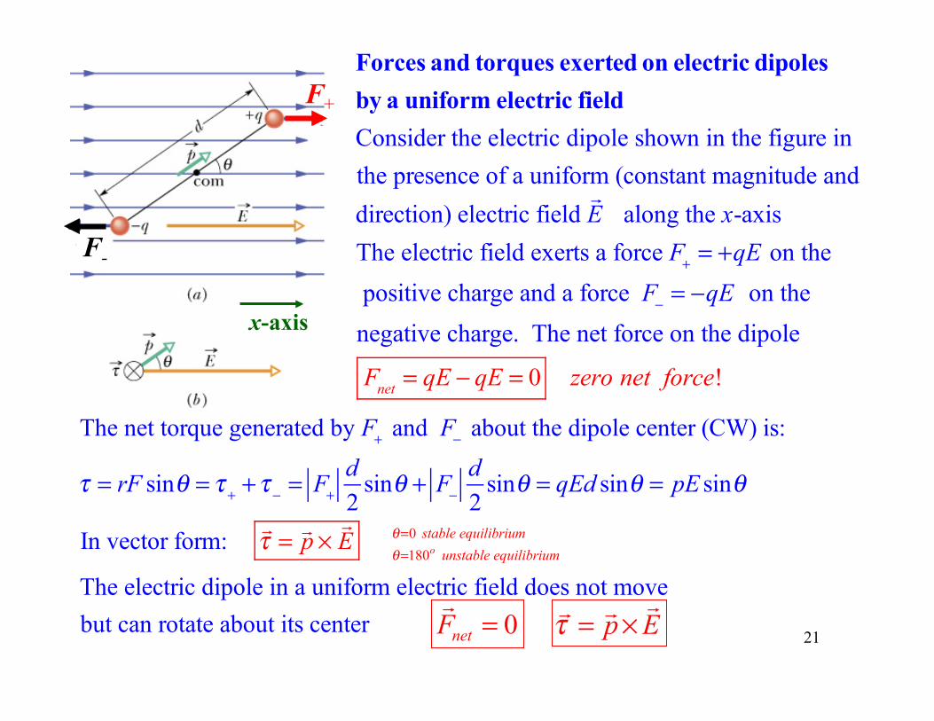
F+
F-
x-axis
Forces and torques exerted on electric dipoles by a uniform electric fieldConsider the electric dipole shown in the figure inthe presence of a uniform (constant magnitude and direction) electric field
!E along the x-axis
The electric field exerts a force F+ = +qE on the
positive charge and a force F− = −qE on the
negative charge. The net force on the dipole
Fnet = qE − qE = 0 zero net force!
The net torque generated by F+ and F− about the dipole center (CW) is:
τ = rF sinθ = τ + +τ − = F+
d2
sinθ + F−
d2
sinθ = qEd sinθ = pE sinθ
In vector form: !τ = !p ×
!E
θ=180o unstable equilibriumθ=0 stable equilibrium
The electric dipole in a uniform electric field does not movebut can rotate about its center p Eτ = ×
!! !0netF =!
21
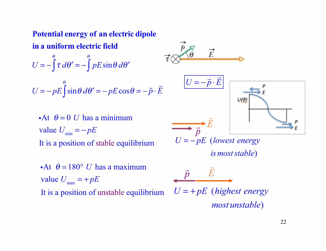
Potential energy of an electric dipole in a uniform electric field
U = − τ d ′θθ
∫ = − pE sinθ d ′θθ
∫
U = − pE sinθ d ′θθ
∫ = − pE cosθ = − !p ⋅!E
p!E!
E!
p!
iAt θ = 0 U has a minimumvalue Umin = − pEIt is a position of stable equilibrium
iAt θ = 180° U has a maximumvalue Umax = + pEIt is a position of unstable equilibrium
22
U = − !p ⋅
!E
U = − pE (lowest energyismost stable)
U = + pE (highest energymost unstable)

23
Practice
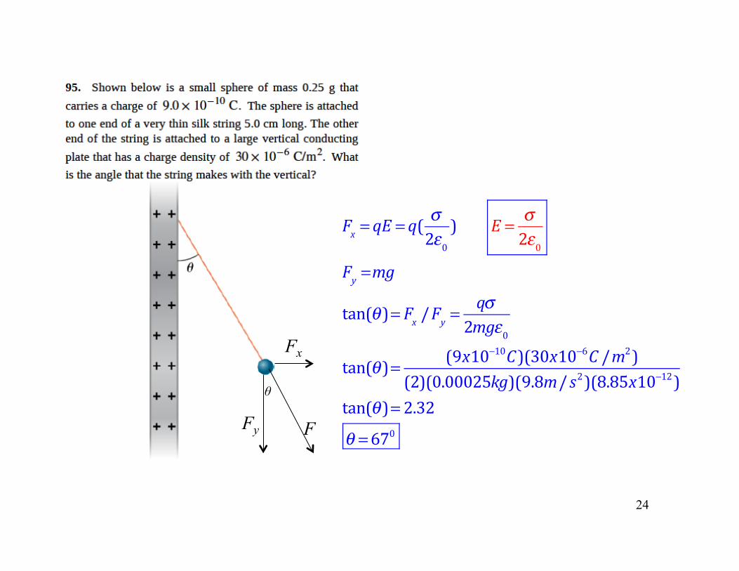
24
Fx = qE = q( σ2ε0) E = σ
2ε0Fy =mg
tan(θ )= Fx /Fy =qσ
2mgε0tan(θ )= (9x10⁻¹⁰C)(30x10−6C /m2)
(2)(0.00025kg)(9.8m/ s2)(8.85x10⁻¹²)tan(θ )= 2.32θ =670
Fx
Fy
θ
F
25
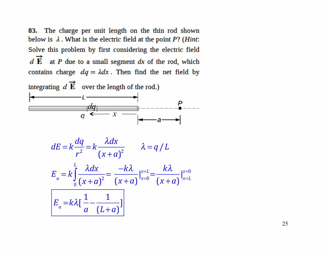
dE = k dqr2
= k λdx(x +a)2 λ = q/L
Ea = kλdx
(x +a)20
L
∫ = −kλ(x +a)|x=0
x=L= kλ(x +a)|x=L
x=0
Ea =kλ[1a− 1(L+a)]
x dq
26
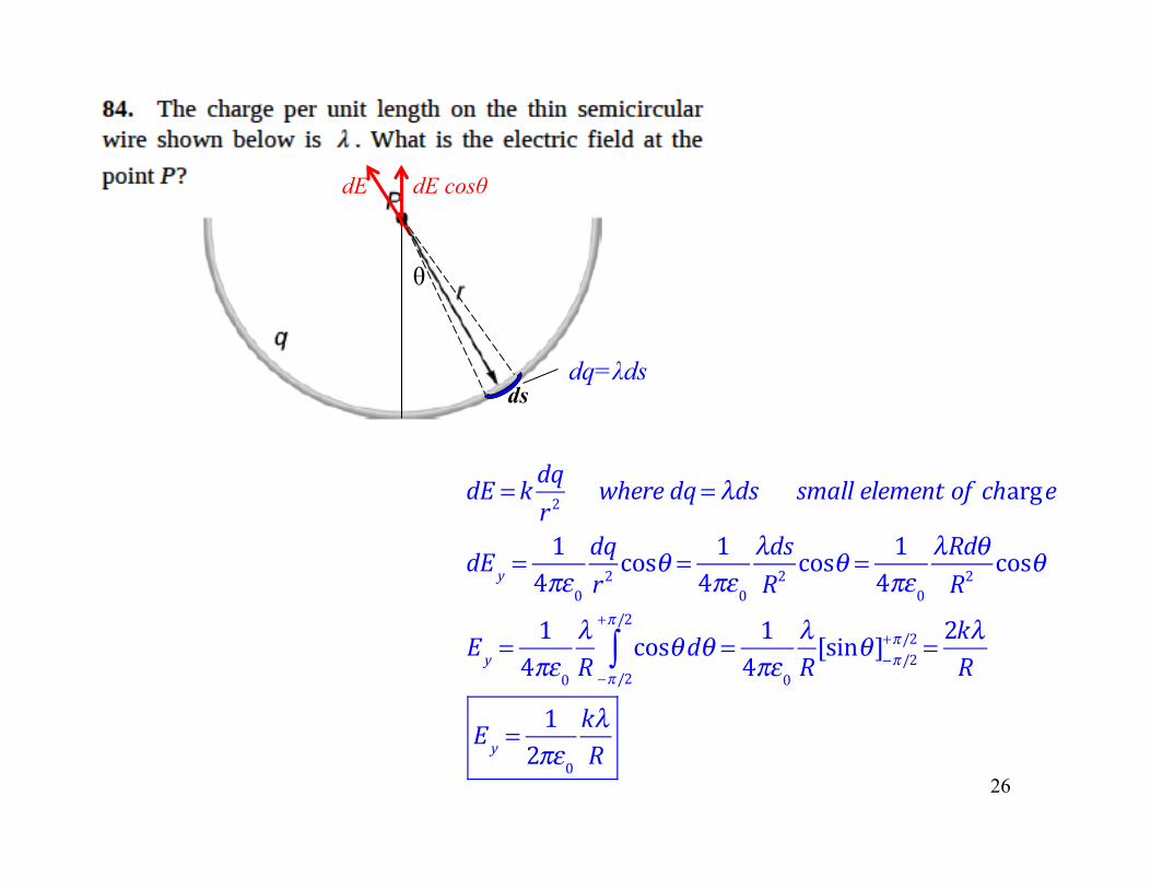
dE = k dqr2
where dq= λds small element of charge
dE y =1
4πε0dqr2cosθ = 1
4πε0λdsR2
cosθ = 14πε0
λRdθR2
cosθ
Ey =1
4πε0λR
cosθdθ−π/2
+π/2
∫ = 14πε0
λR[sinθ ]−π/2+π/2 = 2kλ
R
Ey =1
2πε0kλR
θ
dE cosθ dE
ds dq=λds
27
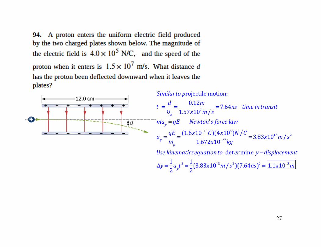
Similarto projectilemotion:
t = dυx
= 0.12m1.57x107m/ s =7.64ns time in transit
may = qE Newton's force law
ay =qEmp
= (1.6x10⁻¹⁹C)(4x10⁵)N /C
1.672x10⁻²⁷kg=3.83x10¹³m/ s2
Use kinematicsequationto determine y −displacement
Δy = 12ayt2 = 12(3.83x10
13m/ s2)(7.64ns)2 = 1.1x10⁻³m

28
STOP HERE
q
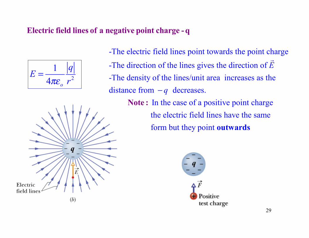
Electric field lines of a negative point charge - q
2
1 4 o
qE
rπε=
-The electric field lines point towards the point charge
-The direction of the lines gives the direction of -The density of the lines/unit area increases as thedistance from decreases.
E
q−N
!
In the case of a positive point charge the electric field lines have the same form but they point
outw
ote :
ards
29
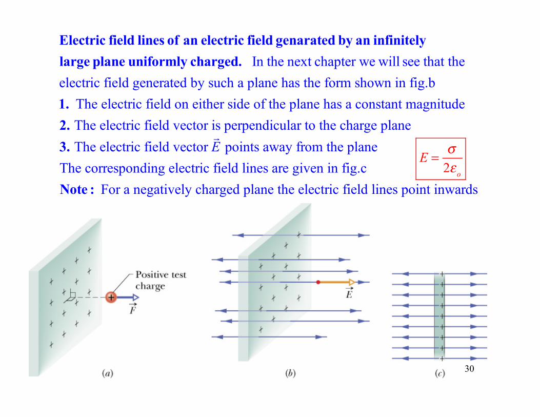
Electric field lines of an electric field genarated by an infinitely large plane uniformly charged. In the next chapter we will see that the electric field generated by such a plane has the form shown in fig.b1. The electric field on either side of the plane has a constant magnitude2. The electric field vector is perpendicular to the charge plane 3. The electric field vector
!E points away from the plane
The corresponding electric field lines are given in fig.cNote : For a negatively charged plane the electric field lines point inwards
30
E = σ
2εo
p!
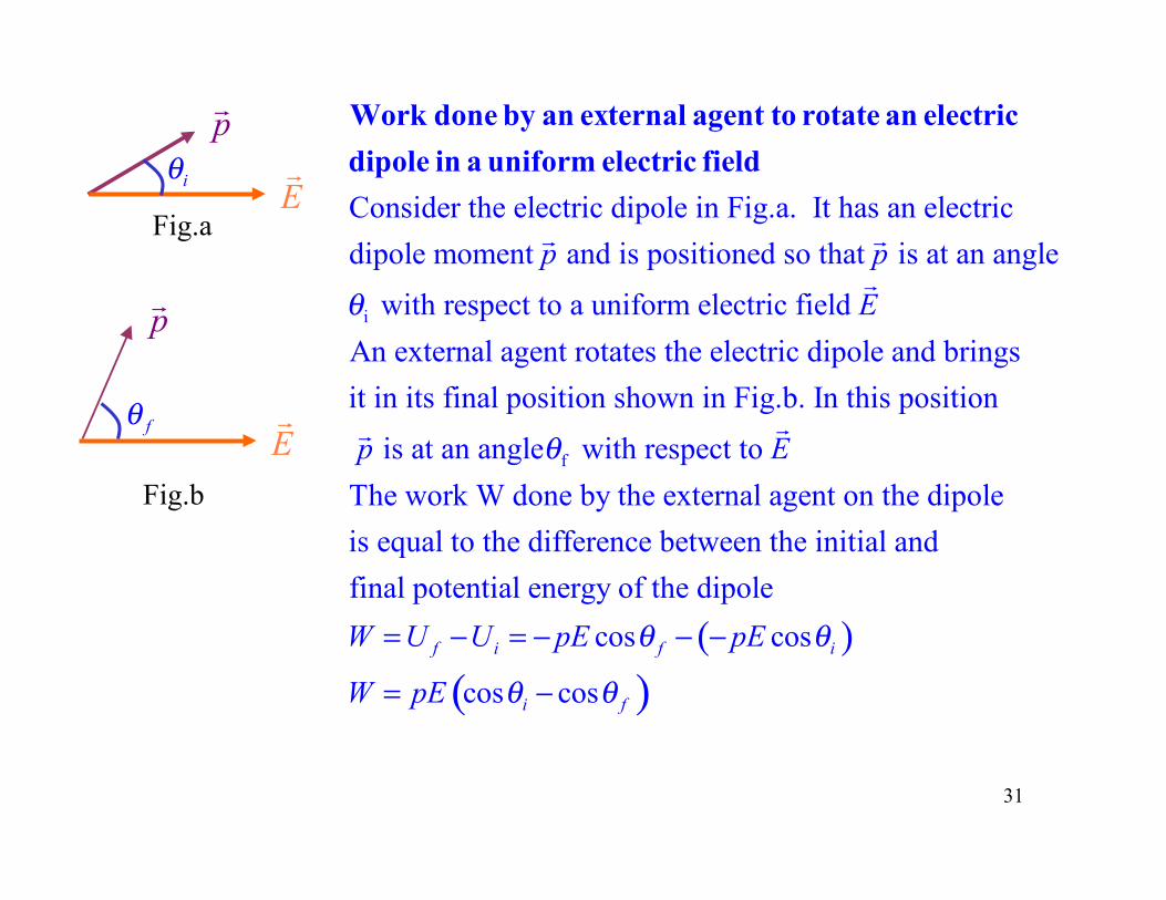
E!fθ
Fig.b
p!
E!iθ
Fig.a Consider the electric dipole in Fig.a. It has an electricdipole moment and is positioned so that is at an p p
Work done by an external agent to rotate an electricdipole in a uniform electric field
! !
i
f
angle
with respect to a uniform electric field An external agent rotates the electric dipole and bringsit in its final position shown in Fig.b. In this position
is at an angle with respect to
E
p
θ
θ
!
!
( )( )
The work W done by the external agent on the dipoleis equal to the difference between the initial andfinal potential energy of the dipole
cos cos
cos cos
f i f i
i f
E
W U U pE pE
W pE
θ θ
θ θ
= − = − − −
= −
!
31