Embed Size (px)
Citation preview

5 - 1
5. Diagnostics The Diagnostics section of the Service Guide help to perform diagnostics in case of problems
affecting the operation and to pinpoint about the source of the problem. The diagnostics can be done directly through the ‘Service’ menu in the Robomow or through the Toolkit software that gives more detailed information in one screen. The Toolkit and the ‘Service’ menu in Robomow have a series of self-diagnostic tests that allow it to pinpoint problems or test systems affecting the operation. By entering the specific system or component test, it will display either a ‘Pass’ or ‘Fail’ message or display a fault code, which is referenced in Section 5.6 to determine the nature of the problem.
This section closely cross-references with Section 3, Troubleshooting. In Section 3, many of the
troubleshooting flow charts request a specific diagnostic test to be performed. The results of each of these diagnostic tests are then used to determine the system or component of failure. This section outlines the procedure for performing these tests as well as an interpretation of the results, found in the Fault Code Tables, Section 5.6.
Contents Subject Page
5.1 General test……………………………………………………………. 5-2 5.2 Service Key Procedure………………………………………………... 5-3 5.3 Toolkit Setup and Main Menu……………………………………….. 5-6 5.4 Toolkit Options………………………………………………………... 5-10
5.4.1 System View………………………………………………………….. 5-10 5.4.2 Tests…………….…………………………………………………….. 5-16 5.4.3 Calibrations…………………………………………………………… 5-17 5.4.4 Settings………………………………………………………………... 5-18 5.4.5 Information……………………………………………………………. 5-19 5.4.5 Downloads……………………………………………………………. 5-20
5.5 Service menu options………………………………………………….. 5-24 5.5.1 Settings procedures……………………………………………….…. 5-24 5.5.2 Calibration procedures……………………………………………… 5-29 5.5.3 Testing procedures…………………………………………………... 5-31
5.6 Diagnostics fault codes……………………………………….….…….. 5-35 5.7 Operation Stop Cause Table…………………………………….…..... 5-37 5.8 Battery Voltage Measurement………………………………………... 5-40 5.9 Charging Current Measurement……………………………………... 5-42

5 - 2
Min 2m (6.5ft)
Min 3m (10ft)
Min 2m (6.5ft)
Min 3m (10ft)
5.1 General Test
The General Test is a basic test that should be performed whenever a technician initiates a service repair on a Robomow. The test is designed so that most common problems found in normal operation will be readily apparent. The General Test should be performed regardless of whether any work was actually performed out on a unit. This ensures a “Duty of Care” to the customer, and will also serve to insure that all safety systems are working properly prior to a customer using the unit.
The General Test should also be performed after any service routine was performed. This will insure that the maintenance was performed correctly and that no additional problems were introduced to the unit during the service routine.
The General Test and certain of the other diagnostics tests need to be performed in a simulated lawn with the layout as shown below:
A. Remove batteries fuse from the Robomow and perform a mechanical inspection:
1. Check the operation of the cutting height adjustment. 2. Confirm the front cover chassis, operating panel and gear cover are closed well in its place. 3. Check that the blade is sharp and securely attached. 4. Check the operation of the front wheel by insuring it is free to rotate in all directions.
B. Clean the unit using compressed air; particularly the mowing decks. A damp cloth and a wooden stick can also be used to remove stubborn dirt and debris. Do not wash with a hose.
C. Insert the batteries fuse and perform the following tests: 1. Check that the operating LED illuminates when the fuse is inserted. 2. Check that the operating panel display and buttons are working properly. 3. Slightly lift the front of the unit and insure that the unit announces the Front Wheel lifted.
Repeat the same test by holding the Front Wheel pressed so it will not activate and lift Robomow to more than 60 degrees to verify the tilt sensor is activated.
4. Confirm that the bumpers are functioning correctly by pressing them and hear the beeps. 5. Check charging using a Power Supply or through the Base Station.
SAFETY FIRST! Before completing the following tests, insure that the test area is clear of persons and obstacles. Remove all floor debris to prevent it from being thrown by the rotating blade. Keep feet and
hands away from the blades and the drive wheels when testing.
Figure 5.1 Simulated Lawn for General Test

5 - 3
D. Using the Remote Control, drive the Robomow manually forwards, backwards, left and right
and perform the ‘Drive motor test’ under the ‘Service’ menu.
E. Manually activate the mowing motors and perform the ‘Mowing test’ under the ‘Service’ menu. F. Operate the Robomow automatically in the simulated lawn. Verify it follow the perimeter wire
in edge mode and move in a straight lines when it moves inside the area in Scan mode.
5.2 Service Key
The Service Key is a function in the Robomow software that allows a service technician to
access diagnostics and service functions. These menu functions are not available to the end user.
There are two ways to unlock the service password protection: § Formula that calculates the required password code based on a counter that is changed every
2 days and called Service Counter. § Master code: ‘01210’ When you are asked to enter the password code the Service Counter is displayed at the right
side of the display inside the brackets. In case of instructing the customer to enter the ‘Service’ menu, it is recommended to use the Service Counter and not the Master code in order to prevent the user to reenter the ‘Service’ Menu in the future. The table in the next pages shows the code required for every Service Counter:

5 - 4
Service Counter
Service Password
Service Counter
Service Password
Service Counter
Service Password
0 00000 52 05356 104 215281 00001 53 05565 105 219452 00006 54 05778 106 223663 00015 55 05995 107 227914 00028 56 06216 108 232205 00045 57 06441 109 236536 00066 58 06670 110 240907 00091 59 06903 111 245318 00120 60 07140 112 249769 00153 61 07381 113 2542510 00190 62 07626 114 2587811 00231 63 07875 115 2633512 00276 64 08128 116 2679613 00325 65 08385 117 2726114 00378 66 08646 118 2773015 00435 67 08911 119 2820316 00496 68 09180 120 2868017 00561 69 09453 121 2916118 00630 70 09730 122 2964619 00703 71 10011 123 3013520 00780 72 10296 124 3062821 00861 73 10585 125 3112522 00946 74 10878 126 3162623 01035 75 11175 127 3213124 01128 76 11476 128 3264025 01225 77 11781 129 3315326 01326 78 12090 130 3367027 01431 79 12403 131 3419128 01540 80 12720 132 3471629 01653 81 13041 133 3524530 01770 82 13366 134 3577831 01891 83 13695 135 3631532 02016 84 14028 136 3685633 02145 85 14365 137 3740134 02278 86 14706 138 3795035 02415 87 15051 139 3850336 02556 88 15400 140 3906037 02701 89 15753 141 3962138 02850 90 16110 142 4018639 03003 91 16471 143 4075540 03160 92 16836 144 4132841 03321 93 17205 145 4190542 03486 94 17578 146 4248643 03655 95 17955 147 4307144 03828 96 18336 148 4366045 04005 97 18721 149 4425346 04186 98 19110 150 4485047 04371 99 19503 151 4545148 04560 100 19900 152 4605649 04753 101 20301 153 4666550 04950 102 20706 154 4727851 05151 103 21115 155 47895
Service Counter and password:

5 - 5
Service Counter
Service Password
Service Counter
Service Password
156 48516 207 85491157 49141 208 86320158 49770 209 87153159 50403 210 87990160 51040 211 88831161 51681 212 89676162 52326 213 90525163 52975 214 91378164 53628 215 92235165 54285 216 93096166 54946 217 93961167 55611 218 94830168 56280 219 95703169 56953 220 96580170 57630 221 97461171 58311 222 98346172 58996 223 99235173 59685 224 00129174 60378 225 01026175 61075 226 01927176 61776 227 02832177 62481 228 03741178 63190 229 04654179 63903 230 05571180 64620 231 06492181 65341 232 07417182 66066 233 08346183 66795 234 09279184 67528 235 10216185 68265 236 11157186 69006 237 12102187 69751 238 13051188 70500 239 14004189 71253 240 14961190 72010 241 15922191 72771 242 16887192 73536 243 17856193 74305 244 18829194 75078 245 19806195 75855 246 20787196 76636 247 21772197 77421 248 22761198 78210 249 23754199 79003 250 24751200 79800 251 25752201 80601 252 26757202 81406 253 27766203 82215 254 28779204 83028 255 29796205 83845206 84666
Service Counter and password (con.):

5 - 6
Application for software download
Service application Driver for the USB to RS-232 adaptor
RS-232 Connector RS-232 to RJ11 Adaptor
5.3 Toolkit Setup and Main Menu
5.3.1 Tools required (Figure 5.2): § A computer at the test bench area § USB to RS-232 adaptor § RS-232 to RJ11 adaptor § Cable with 2 ends of phone jacks (RJ11 connectors) § Service Kit Package
5.3.2 Copy the ‘Service Kit Package’ to your computer. It includes the following:
5.3.3 Copy the ‘RM_Toolkit’ folder to the ‘C’ directory. The ‘RM_Toolkit’ folder MUST be copied to the ‘C’ directory to enable software downloads through the Toolkit application.
5.3.4 Double click to open the 5.3.5 Copy the to Desktop. 5.3.6 Install the driver for the USB to RS-232 adaptor following the instructions in Appendix A
(The Driver for the USB installation is in the ‘USB to Serial’ folder’ – in the Service Kit Package).
5.3.7 Connect the USB to RS-232 adaptor to your PC, when the USB side is connected to the computer, as shown in Figure 5.4 below.
5.3.8 Connect the USB to RS-232 adaptor to the RS-232 to RJ11 adaptor, as shown in Figure 5.5 below.
Figure 5.2 - Tools required
PC
USB to RS-232 adaptor
RS-232 to RJ11 adaptor
Figure 5.4 USB connection to PC
RJ11 cable
Figure 5.3 – Service Kit Package
Figure 5.5 USB to RS-232 Adaptor connection
to RS-232 to RJ11 Adaptor

5 - 7
Robomow
USB to RS-232 Adaptor
Computer
RS-232 to RJ11 Adaptor
RS-232 connection
USB connection
JR11connector
Robomow
USB to RS-232 Adaptor
Computer
RS-232 to RJ11 Adaptor
RS-232 connection
USB connection
JR11connector
5.3.9 Connect the RJ11 cable (phone jack) to the adaptor, as shown in Figure 5.6 and the other
side of the cable to Robomow, as shown in Figure 5.7 (for your convenient, lift the bumper for easier access to the communication socket in the mower).
5.3.10 The following Figure shows the connections from the computer to the Robomow:
Figure 5.6 RJ11 connection to
Adaptor Figure 5.7
RJ11 (phone jack) connection to Robomow
Figure 5.8 Communication between
Robomow and the computer

5 - 8
5.3.11 Double click on the Toolkit icon in the Desktop to open the Toolkit software. The first page of the Toolkit will be opened, where at the top left side of the display, the following options are available (Figure 5.9):
5.3.12 View – ‘Debug window’ uses for Friendly Robotics diagnostic only. 5.3.13 Settings – choosing the ‘Settings’ menu will open the following display (Figure 5.10):
Choose the ‘Communication settings…’ to set the COM in the PC that the Toolkit box is connected to (Figure 5.11). The ‘Baud Rate’ should be set always to ‘19200’ (default).
5.3.14 Help - choosing the ‘Help’ menu will open the following display (Figure 5.12):
Figure 5.9 Toolkit Toolbar
Refer to 5.3.13
Refer to 5.3.12
Refer to 5.3.14
Refer to 5.4.1
Refer to 5.4.2
Refer to 5.4.3
Refer to 5.4.4
Refer to 5.4.5
Figure 5.10 Settings menu
Figure 5.11 Communication
Settings
Figure 5.12 Help Menu
Refer to 5.4.6

5 - 9
Press the ‘About RM Toolkit’ in the ‘Help’ menu to confirm that you are using the most updated Toolkit software version, as shown in Figure 5.13. (Ask your distributor or Friendly Robotics for the most updated Toolkit version).
Press the ‘RM Toolkit Help’ to enter the online help. To have an access to the help pages in the website, it is required to enter ‘User name’ and ‘Password’ (Figure 5.14). Please contact your distributor or Friendly Robotics to receive the ‘User name’ and ‘Password’.
Figure 5.13 About RM Toolkit
Figure 5.14 About RM Toolkit

5 - 10
‘Open’ / ‘Close’ saved files. When ‘Close’ is displayed there is no communication with the robot and the name of the opened file is
displayed as shown below:
Save a file with the displayed values
Click on the ‘Close’ to enable communication with the robot
5.4 Toolkit Options 5.4.1 System View
The System View (Figure 5.15) shows the following information in a real time: - Bumper state and analog readings (refer to paragraph 5.4.1.1) - Cover analog readings (refer to paragraph 5.4.1.2) - Rain sensor analog readings (refer to paragraph 5.4.1.3) - Front Wheel analog readings (refer to paragraph 5.4.1.4) - Tilt state (refer to paragraph 5.4.1.5) - Wire sensors information (refer to paragraph 5.4.1.6) - Remote Control (refer to paragraph 5.4.1.7) - Push buttons in the operating panel (refer to paragraph 5.4.1.8) - Battery and Charging (refer to paragraph 5.4.1.9) - Drive information (refer to paragraph 5.4.1.10) - Mow information (refer to paragraph 5.4.1.11)
Figure 5.15 System View

5 - 11
5.4.1.1 Bumper
The Bumper block shows the bumper state, where there are four options (Figure 5.16): ‘Clear’ if bumper is not detected. ‘Left’ if bumper is pressed from the left side of Robomow. ‘Right’ if bumper is pressed from the right side of Robomow. ‘Front’ if bumper is pressed from the front side of Robomow. When bumper is detected, the box color is changed to blue.
In addition it shows the analog reading of the bumper sensors for the left and right side. You should check that after the bumper is pressed and released, the analog readings are changed back to the original readings displayed in the ‘Clear’ state (+/-3). If the readings are not changed back to the original values, check for dirt or damage in the bumper, bumper shaft and confirm the screws of the bumper shafts are tighten well.
Note: The analog readings of the right and left sensors should not be the same in the ‘Clear’ state, as the distance of the sensor from the magnet is changed between mowers and between the sides.
5.4.1.2 Cover The Cover block shows the cover sensor analog reading (Figure 5.17). When the cover is lifted the box color is changed to blue. When the cover is closed, the reading should be max 5 and when it is lifted it is expected to be higher than 130.
Figure 5.16 Bumper block
Figure 5.17 Cover block

5 - 12
Figure 5.18 Rain sensor block
Figure 5.19 Front Wheel block
Figure 5.20 Front Wheel block
5.4.1.3 Rain Sensor The Rain sensor block shows the analog reading (Figure 5.18). When the reading goes down below 25, the mower detects rain. Normal reading during the season should be 27-29.
5.4.1.4 Front Wheel
The Front Wheel block shows the analog reading of the Drop-off sensor (Figure 5.19). When the Front Wheel is on the ground, the reading should be max 5 and when the Front Wheel is lifted it is expected to be higher than130 and the box color is changed to blue.
5.4.1.5 Tilt The Tilt block shows the state of the tilt sensor (Figure 5.20). The tilt sensor is an optic sensor that detects the situation, which the mower is lifted from the front side in more than 60 degrees. When tilt is detected, the box color is changed to blue.
5.4.1.6 Wire
Note: While working through the Toolkit, the communication causes to noise in the signal, thus it is recommended to test the wire sensors and the signal through the ‘Special display> Sensors> Wire’ and not through the Toolkit.
The Wire block shows the following information (Figure 5.21): - State - In / Out of the wire sensors referring to the perimeter wire loop. - Amplitude - strength of the signal –will be higher as the detected signal is stronger. - Count – digital reading of the sensor readings:
400 – inside the lawn 200 – out of the lawn 0 – no wire signal
- Gain – increasing the signal strength as needed (changed between 0 to 3, where ‘0’ is for very low increasing and ‘3’ is for the highest increasing).

5 - 13
Figure 5.21 Inside the lawn Out of the lawn No wire signal
Figure 5.22 Remote Control block
Manual drive Manual mow
Figure 5.23 Push Buttons block
5.4.1.7 Remote Control The Remote Control block shows if it is activated and which button is pressed (Figure 5.22). The box color is changed to blue when there is transmission from the Remote Control to the mower and the check boxes show, which button is pressed.
5.4.1.8 Push Buttons
The Push Buttons block shows if it is activated and which button is pressed (Figure 5.23). The box color is changed to blue when one of the buttons is pressed.

5 - 14
Figure 5.24 Battery and Charging
block
5.4.1.9 Battery and Charging
The Battery and Charging shows the following information (Figure 5.24): - Box color is blue when the battery is charged. - Charging Stage - The charging process is divided into three stages:
Stage 1 (‘4’ is displayed): Adjust the Charging Power to maintain the max charging current until the battery voltage reaches 29.4V. Stage 2 (‘5’ is displayed): Adjust the Charging Power to maintain a battery voltage of 29.4V. Stage 3 - Floating (‘6’ is displayed): Adjust the Charging Power to maintain a battery voltage of 27.2V until charging process is terminated.
- Charging Voltage – When using 0.9A Power Supply: Expected charging voltage in stage 1 – 30.0V (+/-10%) Expected charging voltage in stage 2 – ~30-37V Expected charging voltage in stage 3 – ~35-37V
- Charging Current – This is the actual charging current. In stage 1 (4) – Max possible charging current. In stage 2 (5)– Changed to control constant voltage of 29.4V. In stage 3 (6)– 0-0.12A
- Charging Power – The Charging Power (PWM) uses to control the parameters in the charging process: In stage one, Robomow changes the Charging Power (PWM) in order to control the max charging current. In stage two, Robomow changes the Charging Power (PWM) in order to control the batteries voltage to 29.4V. In stage three, Robomow changes the Charging Power (PWM) in order to control the batteries voltage to 27.2V. It is expected to be 0-1%.
- Battery Voltage – Expected batteries voltage in stage 1 (4) – goes up until it reaches 29.4V. Expected batteries voltage in stage 2 (5) – 29.4V Expected batteries voltage in stage 3 (6) – 27.2V
- Battery Temperature – battery temperature in Celsius. - Battery Type – Shows the battery type.

5 - 15
Figure 5.25 Drive block
Figure 5.26 Mow block
5.4.1.10 Drive
The box shows the following information, where ‘L’ is for the left drive motor and ‘R’ is for the right one (Figure 5.25):
- Box color is blue when the drive is activated. - Direction – shows the direction (0-359º), where it becomes zero in every ‘GO’ pressing. - Distance – accumulated distance (cm), where it becomes zero in every ‘GO’ pressing. - Power - Drive power (%) - Current - Actual drive motor current.
No load (wheel in the air) – expected current 0.2-0.3A. Over current threshold (default) – 2.0A.
- Temperature - The drive motor temperature. Drive over-heat threshold – 85Cº - Speed - The speed in percent from the max possible speed. - Ticks - The counter of the odometer ticks (turns of the drive motor). - Over-Current - shows indication for drive hardware over-current.
5.4.1.11 Mow The box shows the following information (Figure 5.26):
- Box color is blue when the mow is activated. - Power – shows the mow power (%). - Current – shows the actual mowing current (should be around 1.0A in no load). - Temperature – shows the mow motor temperature. The mow over-heat threshold is 10
minutes above 90Cº or 1 sec 100Cº. - Over-Current – shows indication for mow hardware over-current.

5 - 16
Figure 5.27 Test page
Figure 5.28 Test results
5.4.2 Tests The ‘Tests’ page enables to perform test for the following systems/sensors, as shown in Figure 5.27 below:
All the tests above are available to be performed directly through the ‘Service> Tests’ menu in the Robomow LCD too.
Press the key of the system you want to test. The results of the tests (Figure 5.28) will be a ‘Passed’ or ‘Fail’ with a fault code number. Refer to the fault code in Section 5.7 Diagnostics Fault Codes.
For more details of how to perform the tests procedures refer to section 5.5.3 Tests Procedures.

5 - 17
Figure 5.29 Calibration page
5.4.3 Calibrations The ‘Calibrations’ page enables to perform the calibrations the following systems/sensors, as shown in Figure 5.29 below:
All the calibrations above are available to be performed directly through the ‘Service> Calibrations’ menu in the Robomow LCD too.
Press the key of the system you want to test and simply follow the instructions displayed in the Robomow LCD. The results of the tests will be a ‘Passed’ or ‘Fail’ with a fault code number. Refer to the fault code in Section 5.7 Diagnostics Fault Codes. For more details of how to perform the calibrations procedures, refer to section 5.5.2 Calibrations Procedures.
5.4.4 Settings The ‘Settings’ page enable to receive the settings from the robot, to change them in the
computer (if required) and to send back the updated settings to the robot. This can be use in service mostly when it is required to replace Main Board – this
option enable to keep the settings of the robot (such as Weekly program, entry points, work time and all the others) before the faulty Min Board is replaced, to replace Main Board to the new one and to send back the same settings to the Main Board.
The ‘settings’ page is divided into three main sections, where the upper side of the screen shows the ‘Zones Setup’ settings (user’s level), the left bottom side shows the ‘User Settings’ (Robomow settings at the user’s level) and the right lower side shows the ‘Service Settings’ (Dealer’s level), as shown in Figure 5.30:

5 - 18
Figure 5.30 Settings page
At the bottom of the screen there are four options: Receive Setting From Robot – Press ‘Receive Setting From Robot’ and wait until the display will be updated with the settings from the robot (it may take 40-50 sec). Send Settings To Robot – Press ‘Send Setting To Robot’ and wait until the progress line (the green line at the bottom of the display) is full (it may take few sec). Open / Close – Enables to open a saved file. The file can be opened only when using the Toolkit software. When a file is open the button is changed to ‘Close’ and there is no communication with Robomow. Press the ‘Close’ to enable communication. Save – Enable saving the ‘Settings’ screen as a file. This option is useful in the following: 1. In service when you want to keep the file of the settings so you can use it in the future. 2. When required help from Friendly Robotics in diagnostics of a problem, it is
recommended to attached three files (System View, Settings and Information) as it will save questions and time in the diagnostics process.
To change the setting, press the sign and choose the required setting. In case the setting is blocked for change, its window color will be gray – only the white boxes are available for updating. All the settings are explained in details in Chapter 2 – Menu Items.

5 - 19
Figure 5.31 Information page
Figure 5.32 Configuration
5.4.5 Information
The ‘Information’ page shows the ‘Information’ received from the robot (Figure 5.31). It displays the same information that is available in the ‘Information’ menu in the mower, but it is more convenient to see all the information in one page with no need to scroll between all the screens.
When required help from Friendly Robotics in diagnostics of a problem, it is recommended to attached three files (System View, Settings and Information) as it will save questions and time in the diagnostics process.
The ‘Configuration’ is displayed in a different way (figure 5.32) from the way it is displayed in the ‘Information’ menu in the Robomow itself. Main Board: 1 – ESB5000E
Software: 1 – RM200 5.2v 25/11/07 2 – RM400 5.4v 25/11/07
Base Station: Software version of the base Station Board 27 à 1.27v

5 - 20
Figure 5.34 Perform ‘Reset’ before software download
5.4.6 Downloads
This option enables to download software version from the computer to the Robomow using the Toolkit application. There is another option to download software through the FTP application (please refer to Appendix A numbers 1 to 21). 5.4.6.1 Choose the ‘Download’ page and press the ‘Download Software Version’ button
(Figure 5.33):
5.4.6.2 Perform reset in Robomow (Figure 5.34) before proceeding to the software download process by one of the following options: a. Press the On/ Off button continually for 4 seconds (there is no indication from
Robomow after the reset is done). b. Remove the batteries fuse from Robomow for 2 seconds and reinsert. Press OK to proceed.
Figure 5.33 Download Software Version
5 - 21
Figure 5.35 Choose the software you want to download
Figure 5.36 Press ‘Browse’ to find the RM id file
Figure 5.37 Choose the RM.id file
5.4.6.3 Choose the software to be downloaded and press the ‘Open’ button (Figure 5.35).
5.4.6.4 The display in Figure 5.36 will be opened. Press the ‘Browse…’ button.
5.4.6.5 Choose the and press the ‘Open’ button (Figure 5.37).

5 - 22
Figure 5.38 Press ‘Browse’ to find the RM id file
Figure 5.39 Download Process: Success
5.4.6.6 The new screen with the ID will be displayed. Presses ‘OK’ to proceed in the
software download process (Figure 5.38).
5.4.6.7 Wait until the download process is completed. If the download is completed successfully, the following screen is displayed (Figure 5.39) with ‘Download Process: Succeed’ message at the bottom line.

5 - 23
5.4.6.8 If the download process was completed successfully, you can choose between the
following options: a. Continue downloading software to other mower; then you need to press again
the , to perform reset and repeat the same process, but
with no need to set again the RM ID. It is required to perform Reset in every
Robomow after the software download is completed.
b. Go out from the ‘Download’ page and change to the other Toolkit options;
5.4.6.9 If the software download process fails, check/ perform the following: - Perform reset to the Robomow before starting the download process; - Check connection to the Robomow; - Check connection to the PC; - Close and reopen the Toolkit application; - Confirm communication is enabled (using the ‘System view’ page of the
Toolkit).

5 - 24
ChargingConfirm
ChargingConfirm
TemperaturesConfirm
TemperaturesConfirm
BehaviorConfirmBehaviorConfirm
Drive motorsConfirm
Drive motorsConfirm
Mowing motorConfirm
Mowing motorConfirm
BaseConfirm
BaseConfirm
Special displaysPress GO
Special displaysPress GO
Special displaysPress GO
SensorsPress GOSensors
Press GOSensors
Press GOWire sensors
Press GO
BumperPress GO
Front wheelPress GO
CoverPress GO
Wire sensorsPress GO
Wire sensorsPress GO
BumperPress GOBumper
Press GO
Front wheelPress GO
Front wheelPress GO
CoverPress GO
CoverPress GO
5.5 Service Menu Options
The Service menu, while accessed under the User Options screen, is not a customer menu option. It is only to be used by a trained service technician and requires a specific 5-digit code to be entered in order to access the sub-menus.
Various settings, calibrations and tests are found under the ‘Service’ menu that may be used by the technician. Each of these tests is selectable by simply scrolling through the menu. After completing work in a specific area, perform the test shown in the procedure and then perform the General Test outlined in Section 5.1. This will insure that the repair has been done properly and that the unit functions satisfactorily.
The results of some tests will be a pass or fail while others will display a fault code number. Refer to the fault code in Section 5.6 Diagnostics Fault Codes.
Please follow the instructions for each test carefully. At the end of each test press the ‘STOP’ button to exit. Continual pressing of the ‘STOP’ button will move you up through the menu levels, until you arrive at the Main Menu.
Too busy, lack of time or do not understand the test fully: At least operate the Robomow on the test area in automatic mode, to make sure it is fully operational.. The Robomow has built in warning and indication system that will pop up on the display in Automatic mode in case you forgot to perform any of the needed calibrations after service. 5.5.1 Settings Procedures Only the Special Display is cover in this chapter as all the others settings are explained in Chapter 2 – Menu Items. The ‘Special Display’ is the most useful tool for diagnostics.
5.5.1.1 Special display Choosing the ‘Special display’ option enables to display the relevant parameters to tested process (such as temp, volt and sensor readings) and to perform detailed diagnostics. After a specific display is selected use the ‘STOP’ button to toggle between normal and special display, and the ‘ON/OFF’ button to terminate the special display.
Figure 5.33 Special display menu

5 - 25
Wire In this display the LCD will display the following information: ************************************************************************************** 1) Left amplitude 2) left in/out count 3) left gain 4) wire sensor state 5) Right amplitude 6) right in/out count 7) right gain 8) maximal wire gain ************************************************************************************** 1. Left amplitude (Strength of the signal). 2. Left in/out count (400 – in / 200 – out / 0 – no signal). 3. Left Gain (increasing the signal strength as needed). Wire gain (0-Very Low 1-Low 2-Mid 3-High). 4. Sensors state. 0-Both in 1-Right out 2-Left out 3-Both out 5. Right amplitude (Strength of the signal). 6. Right in/out count (400 – in / 200 – out / 0 – no signal). 7. Right gain (increasing the signal strength as needed). Wire gain (0-Very Low 1-Low 2-Mid 3-High). 8. Maximal allowed wire gain (3 in Scan / 1 in Edge). Bumper In this display the LCD will display the following information: ************************************************************************************* 1) Left reading 2) left idle threshold 3) left detection threshold 4) state 5) Right reading 6) right idle threshold 7) right detection threshold 8) sensitive bumper ************************************************************************************* 1. Left reading (A/D). 2. Left idle threshold (A/D reading / 10). 3. Left detection threshold (A/D reading / 10). 4. Sensor state
0=clear 1=left 2=right 3=front 5. Right reading (A/D). 6. Right idle threshold (A/D reading / 10). 7. Right detection threshold (A/D reading / 10) 8. Sensitive bumper detection
0=not detected 1=detected Front Wheel In this display the LCD will display the following information: ************************************************************************************* 1) Reading 2) idle threshold 3) detection threshold 4) state 5) 6) 7) 8) ************************************************************************************* 1. Reading (A/D). 2. Idle threshold (A/D reading / 10). 3. Detection threshold (A/D reading / 10). 4. Sensor state
0=on the ground 1=lifted

5 - 26
Cover In this display the LCD will display the following information: ************************************************************************************* 1) Reading 2) idle threshold 3) detection threshold 4) state 5) 6) 7) 8) ************************************************************************************* 1. Reading (A/D). 2. Idle threshold (A/D reading / 10). 3. Detection threshold (A/D reading / 10). 4. Sensor state
0=closed 1=lifted Charging In this display the LCD will display the following information: ************************************************************************************* 1) Charging voltage 2) charging current 3) Charging PWM 4) charging stage 5) Battery voltage 6) charger current supply 7) charger source 8) stage 1 time ************************************************************************************* 1. Charging voltage (10mV resolution)
When using 0.9A Power Supply: Expected charging voltage in stage 1 – 30.0V (+/-10%) Expected charging voltage in stage 2 – greater than 30.0V Expected charging voltage in stage 3 – 34-38V
2. Charging current (10mA resolution) – This is the actual charging current. Stage 1 - Robomow changes the Charging Power (PWM) in order to control the charging current to the max. Stage 2 – charging current is changed between 0.2-07A Stage 3 – 0-0.12A
3. Charging Power (PWM) The Charging Power (PWM) uses to control the parameters in the charging process: In stage one, Robomow changes the Charging Power (PWM) in order to control the max charging current. In stage two, Robomow changes the Charging Power (PWM) in order to control the batteries voltage to 29.4V. In stage three, Robomow changes the Charging Power (PWM) in order to control the batteries voltage to 27.2V. It is expected to be 0-1%.
4. Charging stage: 4 – Stage 1 5 – Stage 2 6 – Stage 3 (Floating)
5. Battery voltage (10mV resolution) Expected batteries voltage in stage 1 – goes up until it reaches 29.4V Expected batteries voltage in stage 2 – 29.4V Expected batteries voltage in stage 3 – 27.2V
5 - 27
6. Charger current supply (in 10mA resolution)
The Power Supply current set in the software version. The defaults set in the software are: RM400 Base Station – 0.9A RM400 Winter Charger – 0.3A RM200 Regular Power Supply – 0.9A
7. Charger source 0=unknown 1=Base station 2=Regular charger
8. First charging stage time (hours)
Temperatures In this display the LCD will display the following information: ************************************************************************************* 1) Left drive temperature 2) right drive temperature 3) 4) 5) Row temperature 6) Main board temperature 7) 8) ************************************************************************************ 1. Left drive temperature (ºC) 2. Right drive temperature (ºC) 3. 4. 5. Mow temperature (ºC) 6. Main board temperature (ºC) Behavior In this display the LCD will display the following information: ************************************************************************************* 1) Edge distance 2) Last termination event 3) Edge quarters 4) Scan type 5 ) Last turn angle 6) Last leg distance 7) Corner legs number 8) Narrow passage legs number ************************************************************************************* 1. Edge distance (meters) 2. Last termination event (which terminated the head movement during scan) 0 = None 4 = Distance 5 = Time 6 = Wire 7 = Bumper 8 = Front wheel 9 = Drive overcurrent 3. Edge quarters 4. Scan type 1=random 2= parallel 5. Last turn angle during scan (Degrees) 6. Last leg distance during scan in (10cm resolution) 7. Number of corner legs detected 8. Number of narrow passage legs detected

5 - 28
Drive Motors In this display the LCD will display the following information:
****************************************************************************** 1) Left current 2) left temperature 3) left over-current 4) over-current count 5) Right current 6) right temperature 7) right over-current 8) total over-current events ****************************************************************************** 1. Left drive current (10mA resolution) 2. Left drive temperature (ºC) 3. Left hardware drive over-current 0-not detected 1-detected 4. Over-current counter 5. Right drive current (10mA resolution) 6. Right drive temperature (ºC) 7. Right hardware drive over-current 0-not detected 1-detected 8. Total over-current events in the current operation Mowing Motor In this display the LCD will display the following information: ************************************************************************************** 1) Current 2) temperature 3) over-current 4) over-current count 1 5) Motor on/off reason 6) 7) total over-current events 8) over-current count 2 ************************************************************************************** 1. Mow current (10mA resolution) 2. Mow temperature (ºC) 3. Hardware mow over-current (0-not detected 1-detected 4. Over-current counter 1 5. The reason mowing motor is on or off 1 – mow motor is disabled because the mow on/off menu option is set to off 2 – mow motor is halted 3- mow motor is disabled because bumper is detected 4 - mow motor is disabled because front wheel is detected 5 - mow motor is disabled because cover is detected 6 - mow motor is disabled because tilt is detected 7 - mow motor is disabled because robot is during charging 8 – mow motor is disabled because we are during exiting the base due to charging problem 9 – mow motor is disabled because wire sensors are outside the plot for a long time 10 – mow motor is on because we are during automatic operation and mow motor should be on 11 - mow motor is on because we are during manual mowing 12 - mow motor is on because we are during mowing motor stuck test 13 - mow motor is on because we are during mowing test 14 – mow motor is disabled because we are during demo version 15 - mow motor is disabled because we are during final test version 6. Total over-current events in the current operation 7. Over-current counter 2

5 - 29
Wire sensorsCalibrate
Turn off signalthen press GO
Turn on signalthen press GO
PassedPress GO
Wire sensorsCalibrate
Wire sensorsCalibrate
Turn off signalthen press GOTurn off signalthen press GO
Turn on signalthen press GOTurn on signalthen press GO
PassedPress GOPassed
Press GO
Front wheelCalibrate
Place on groundthen press GO
Lift mowerthen press GO
PassedPress GO
Front wheelCalibrate
Place on groundthen press GO
Lift mowerthen press GO
Front wheelCalibrate
Front wheelCalibrate
Place on groundthen press GO
Place on groundthen press GO
Lift mowerthen press GO
Lift mowerthen press GO
PassedPress GOPassed
Press GO
Base In this display the LCD will display the following information: ************************************************************************************** 1) Primary wire 2) Secondary wire 3) 4) 5 ) Base version 6) Grass sensor reading 7) 8) ************************************************************************************* 1. Primary wire reading 0-1 = disconnected 2 = long cable or poor connection 3-7 = good signal 2. Secondary wire reading 0-1 = disconnected 2 = long cable or poor connection 3-7 = good signal 3. 4. 5. Base station board version 6. Grass sensor reading 0-6 = grass sensor reading 7-15 = grass sensor disconnected
5.5.2 Calibrations Procedures
5.5.2.1 Wire Sensors Wire sensors calibration is the process of teaching the wire sensors their position relative to the mower as well as to the signal of the perimeter wire.
This menu is available just for backup, just in case that a problem was happened while writing to the EEPROM or in case which one of the wire sensor coils is wrapped in the opposite direction to the default. This process is done in Friendly Robotics and there is no need to perform it at any time.
5.5.2.2 Front Wheel Calibration
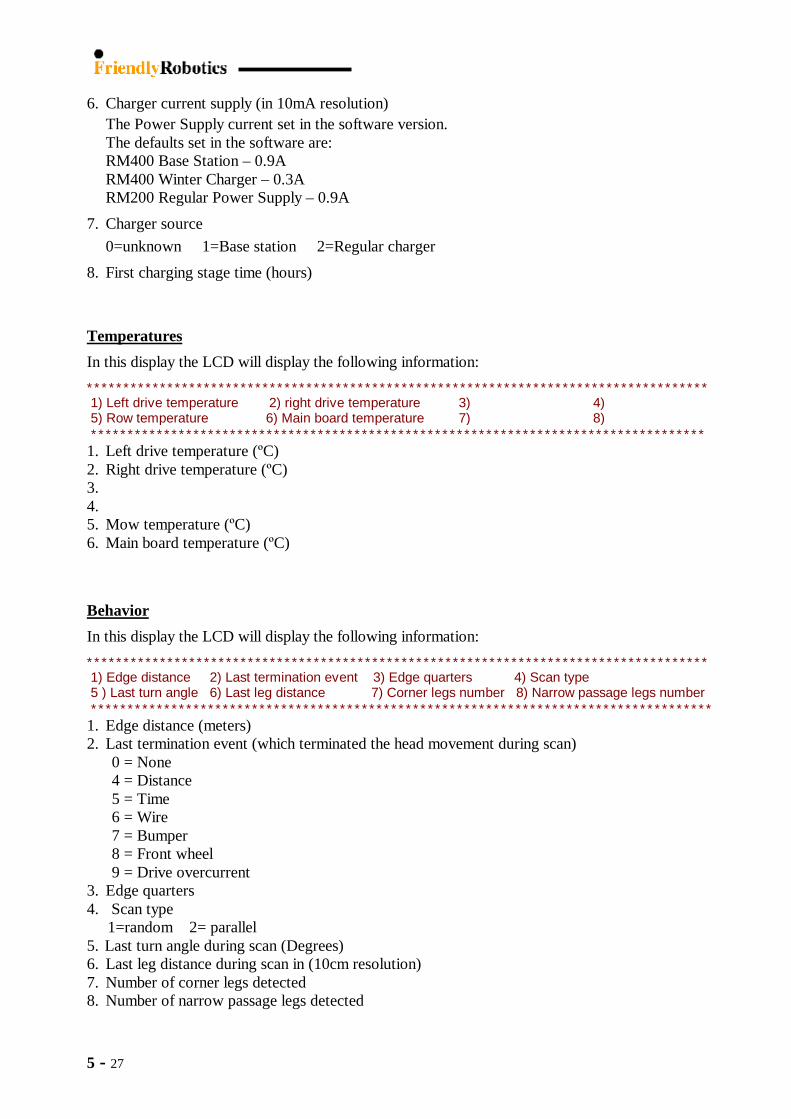
‘Front wheel’ calibration MUST be performed after Factory default (Main Board) is done - Robomow will instruct you to complete the required steps, as shown below:
Figure 5.34 Wire sensors
Calibration menu
Figures 2.28 Front wheel Calibration menu
5 - 30
Close coverthen press GO
Close coverthen press GO
Lift coverthen press GO
Lift coverthen press GO
PassedPress GOPassed
Press GO
BumperCalibrateBumperCalibrateBumperCalibrate
Rotate bumperthen press GORotate bumperthen press GO
Press bumperthen press GOPress bumperthen press GO
Rotate bumper for both directions as much you can although it is very difficult to rotate the joystick and the rotating strong is very short
5.5.2.3 Bumper Calibration ‘Bumper’ calibration MUST be performed after Factory default (Main Board) is done - Robomow will instruct you step by step to complete the required calibrations, as shown below:
A. Close cover B. Lift cover C. Rotate bumper
Figure 5.35 Bumper Calibration menu

5 - 31
VoltageCalibrate
25.2VConfirm
VoltageCalibrateVoltage
Calibrate25.2V
Confirm25.2V
Confirm
25.225.2
5.5.3.1
5.5.3.2
5.5.3.3
5.5.3.4
Sensors
Drive motors
Mowing motor
Edge termination
SettingsCalibrations
TestsService
D. Press bumper
Press bumper for both directions, once to the right side then to the left (there is no need to press the joystick forwards or backwards).
5.5.2.4 Voltage Calibration Option to calibrate the batteries voltage. There is no need to perform this calibration at any time, as it is done in the factory. The battery voltage read by the software should be +/-0.2V from the reading done through voltmeter – in case the different is higher then a voltage calibration should be done.
5.5.3 Tests Procedures
Figures 5.36 Bumper Calibration procedure
Figures 5.38 Tests menu
Figures 5.37 Voltage Calibration menu

5 - 32
Turn on signalthen press GO
Wire sensorsPress GO
Turn off signalthen press GO
Activate motors?Confirm
PassedPress GO
Turn on signalthen press GOTurn on signalthen press GO
Wire sensorsPress GO
Wire sensorsPress GO
Turn off signalthen press GOTurn off signalthen press GO
Activate motors?Confirm
Activate motors?Confirm
PassedPress GOPassed
Press GO
Sensors
Drive motors
Mowing motor
Edge termination
5.5.3.1
5.5.3.2
5.5.3.3
5.5.3.4
Wire sensors
Bumper
Front wheel
Cover
Tilt
Rain sensor
5.5.3.1.1
5.5.3.1.2
5.5.3.1.3
5.5.3.1.4
5.5.3.1.5
5.5.3.1.6
5.5.3.1 Sensors
The ‘Sensors’ tests menu includes the following tests procedures: 5.5.3.1.1 Wire Sensors Test
The ‘Wire sensors’ tests the operation of the two wire sensors on the mower. This test contains 2 steps. The first step in with wire signal turned on and the second one is with wire signal turned off. Step1 This step should be performed when robot is inside the plot and wire signal is on. The following message will be displayed to the user ‘Turn on signal – then press GO’ In this test the following is tested: − Wire signal is detected − Robot is inside the plot − Wire readings are ok Step2 This step should be performed when wire signal is off. The following message will be displayed to the user ‘Turn off signal – then press GO’ In this test the following is tested: − Drive motors are turned on in order to see if wire readings abnormal noises are detected
(this is done to make sure that the wiring of the wire system was done correctly).
If test fails failure number will be displayed (Refer to the fault code in Section 5.6 Diagnostics Fault Codes) and if test passes then ‘Passed’ message will be displayed.
Figures 5.39 Sensors tests menu
Figures 5.40 Wire sensors test menu
5 - 33
5.5.3.1.2 Bumper Test
Press the bumper from different directions. If test fails failure number will be displayed (Refer to the fault code in Section 5.6 Diagnostics Fault Codes) and if test passes then the following will be displayed:
Sensor state Display Bumper not detected -
Sensitive bumper * Front bumper ^ Left bumper <
Right bumper > 5.5.3.1.3 Front Wheel Test
If test fails failure number will be displayed (Refer to the fault code in Section 5.6 Diagnostics Fault Codes) and if test passes then the following will be displayed:
Sensor state Display Front Wheel on the ground -
Front Wheel lifted ^ 5.5.3.1.4 Cover Test
If test fails failure number will be displayed (Refer to the fault code in Section 5.6 Diagnostics Fault Codes) and if test passes then the following will be displayed:
Sensor state Display Cover closed - Cover lifted ^
5.5.3.1.5 Tilt Test
If test fails failure number will be displayed (Refer to the fault code in Section 5.6 Diagnostics Fault Codes) and if test passes then the following will be displayed:
Sensor state Display Tilt not detected -
Tilt detected ^ 5.5.3.1.6 Rain Sensor Test
If test fails failure number will be displayed (Refer to the fault code in Section 5.6 Diagnostics Fault Codes) and if test passes then ‘Passed’ message will be displayed.

5 - 34
5.5.3.2 Drive Motors
This test should be performed when robot is in the air or on a floor and not on the grass where drive over current can occur.
If test fails failure number will be displayed (Refer to the fault code in Section 5.6 Diagnostics Fault Codes) and if test passes then ‘Passed’ message will be displayed.
5.5.3.3 Mowing Motor Mowing motors is the process of testing the mowing motor system of the mower. It has one basic level of testing. This test should be performed when robot is not on the grass where mow over current can occur. If test fails failure number will be displayed (Refer to the fault code in Section 5.6 Diagnostics Fault Codes) and if test passes then ‘Passed’ message will be displayed.
5.5.3.4 Edge Termination Is used for testing the edge mode in case, which the mower does not complete the edge all around the perimeter or when the mower does not drive back to the Base Station at the end of the operation. After this test is selected, operate the mower in Edge mode. At the end of the edge, the mower will display a ‘Test result: X’, which is the reason for Edge termination in this performed test.
Here are the optional Edge termination reasons: 1 – Minimal Edge quarters count 2 – Maximal Edge quarters count 3 - No change in edge quarters for a long time, which probably means the robot is get stuck 4 - Required edge distance reached 5 - Base station detected in a none Base zone 6 - Base station detected while looking for an entry point 7 - Required entry point reached 8 - Edge ended because of drive over current 9 - Edge ended because of drop-off 10 – Edge ended because robot is stuck in place
Figures 5.41 Drive test -
wheel in the air

5 - 35
5.6 Diagnostics Fault Codes Table
Failure Number
Failure Reason Solution
1 Left Bumper pressed reading is equal or smaller than Left Bumper idle reading
Perform calibrationRefer to Flow chart 3.2.9.2
2 Right Bumper pressed reading is equal or smaller than Right Bumper idle reading
Perform calibrationRefer to Flow chart 3.2.9.2
3 Difference between Left Bumper pressed reading and Left Bumper idle reading is too small.
Perform calibrationRefer to Flow chart 3.2.9.2
4 Difference between Right Bumper pressed reading and Right Bumper idle reading is too small.
Perform calibrationRefer to Flow chart 3.2.9.2
7 Left bumper disconnectedreading < 50
Check wiringRefer to Flow chart 3.2.9.2
8 Right bumper disconnectedreading < 50
Check wiringRefer to Flow chart 3.2.9.2
12 Front wheel lifted reading is equal or smaller than Front wheel not lifted reading
Perform calibrationRefer to Flow chart 3.2.8.1
13 Difference between Front wheel lifted reading and Front wheel idle reading is too small.
Perform calibrationRefer to Flow chart 3.2.8.1
22 Cover lifted reading is equal or smaller than Cover not lifted reading
Perform calibrationRefer to Flow chart 3.2.9.3
23 Difference between cover lifted reading cover not lifted reading is too small.
Perform calibrationRefer to Flow chart 3.2.9.3
31 Bad battery voltage calibration Perform voltage calibration
32 Unknown battery typeIf auto battery type detection does not work then constant battery type setting should be used
41 Wire signal off reading is higher than wire signal on reading Perform calibrationRefer to Flow chart 3.2.10.1
42 Difference between wire signal off reading and wire signal on reading is too small.
Perform calibrationRefer to Flow chart 3.2.10.1
43 wire reading indicates calibration failed because we detect that in/out readings are bad
Perform calibrationRefer to Flow chart 3.2.10.1
44Wire reading indicates calibration failed because we detect that robot is not inside the garden during the calibration with signal on
Perform calibrationRefer to Flow chart 3.2.10.1
45 Wire test failed because wire signal is not detected
46 Wire test failed because robot is not inside the plot
47 Wire test failed because of invalid wire in /out count during the wire signal on test
48 Wire test failed because wire signal is detected
49 Wire test failed because of valid wire in /out count during the wire signal off test
5 - 36
Failure Number
Failure Reason Solution
51 Mow thermistor disconnected Check wiringRefer to Flow chart 3.2.3.2
52 Mow motor is disconnected Check wiringRefer to Flow chart 3.2.3.2
53 Mow test failed because of mow overcurrent detection Refer to Flow chart 3.2.3.2
54 Mow test failed because of mow motor is disconnected Check wiringRefer to Flow chart 3.2.3.2
55 Mow test failed because mow motor was disabled for some reason during the test
61 Left drive thermistor disconnected Check wiringRefer to Flow chart 3.2.7.1
62 Right drive thermistor disconnected Check wiringRefer to Flow chart 3.2.7.1
63 Left drive motor disconnected Check wiringRefer to Flow chart 3.2.7.1
64 Right drive motor disconnected Check wiringRefer to Flow chart 3.2.7.1
65 Left drive odometer problem Check wiringRefer to Flow chart 3.2.7.1
66 Right drive odometer problem Check wiringRefer to Flow chart 3.2.7.1
67 Drive test failed because of drive overcurrent detection Refer to Flow chart 3.2.7.1
68 Drive test failed because of left drive motor disconnection detection
Check wiringRefer to Flow chart 3.2.7.1
69 Drive test failed because of right drive motor disconnection detection
Check wiringRefer to Flow chart 3.2.7.1
70 Drive test failed because of left drive odometer problem Check wiringRefer to Flow chart 3.2.7.1
71 Drive test failed because of right drive odometer problem Check wiringRefer to Flow chart 3.2.7.1
72 Drive test failed because left drive motor current is too high Refer to Flow chart 3.2.7.1
73 Drive test failed because right drive motor current is too high Refer to Flow chart 3.2.7.1
81 Rain sensor disconnected Check wiring

5 - 37
5.7 Operation Stop Cause Table Stop
cause number
Message Description
1 No message User tries to initiate operation before the one time setup is completed
2 No message STOP button is pressed during automatic operation 3 No message Edge termination test is completed 4 Close cover Cover lift is detected 5 Splice wire The base station indicates that primary wire loop is
disconnected 6 Splice wire The base station indicates that secondary wire loop is
disconnected 7 Check wire The base station indicates that primary wire loop
connection is poor 8 Check wire The base station indicates that secondary wire loop
connection is poor 9 Rain detected The base station indicates that the grass is wet
10
Start inside
Or
Change wires in plot connector
Automatic operation was initiated by the user while robot is not inside the plot
Wires in plot connector are inverted
11 No wire signal No wire signal is detected when automatic operation is initiated
12 No wire signal No wire signal is detected during automatic operation 13 Replace blade after 200
hours Mowing blade should be replace
14 Change wires in plot connector Wires in plot connector are inverted
15 Failure: 32 Battery type is unknown 16 Recharge battery Low battery voltage is detected during automatic operation 17 Low battery Very low battery voltage is detected during automatic
operation 18 No message Remote control communication is detected during
automatic operation 19 Time completed Timeout is detected during automatic operation 20 Start elsewhere Drive over-current is detected during automatic operation 21 Start elsewhere Drive over-current is detected during remote control
operation 22 Check mow height Mow over-current is detected during automatic operation
23 Check mow height Mow over-current is detected during remote control operation
24 Rain detected Rain is detected during automatic operation 25 Drive overheat Drive overheat is detected during automatic operation 26 Mow overheat Mow overheat is detected during automatic operation 27 Mow overheat Mow overheat is detected during remote control operation 28 Drive overheat Drive overheat is detected during remote control operation 29 Check power Robot got off the base station because charging voltage is
not detected 30 High temperature Robot got off the base station because battery temperature
is too high

5 - 38
Stop
cause number
Message Description
31 Low temperature Robot got off the base station because battery temperature is too low
32 Charging failure Robot got off the base station because charging current is not detected
33 Stuck in place (if robot is inside the plot) Cross outside (if robot is outside the plot)
Robot is stuck in place during automatic operation.
Consecutive turn movements are received without any heading movements
34 Start elsewhere Wire escape is detected during automatic operation 35 Base problem Robot failed to connect to the base station for several times 36 Bumper pressed Bumper detected when automatic operation is initiated 37 Frnt wheel prob Front wheel detected during when automatic operation is
initiated 38 Frnt wheel prob Front wheel detected for a long time during automatic
operation 39 No message Power Supply overheats detected during the charging
process. 40 No message Delayed operation was stopped because operation was
activated during the inactive hours 42 Remove fuse then check
blade Mow motor is stuck
44 No message ON/OFF button is pressed during automatic operation
45 Stuck in place Robot is stuck in place during automatic operation. Robot is performing forward legs without receiving any termination event such as wire or bumper, which means it, is stuck.
46 Reposition Base Robot received a bumper event while searching for the Base station during the Base position one time setup operation
47 No message Robot waited in place for too long during the wire position test waiting for the user to continue the test
48 Key pressed STOP / ONOFF button is constantly pressed and user is trying to start an automatic operation.
49 Remove fuse before lifting Tilt is detected
601 Bumper - calibrate Represents Failure number 1 (look under system failures for more information)
602 Bumper - calibrate Represents Failure number 2 (look under system failures for more information)
603 Bumper - calibrate Represents Failure number 3 (look under system failures for more information)
604 Bumper - calibrate Represents Failure number 4 (look under system failures for more information)
605 Bumper - calibrate Represents Failure number 5 (look under system failures for more information)
606 Bumper - calibrate Represents Failure number 6 (look under system failures for more information)
607 Failure: 7 Represents Failure number 7 (look under system failures for more information)
608 Failure: 8 Represents Failure number 8 (look under system failures for more information)

5 - 39
Stop
cause number
Message Description
611 Failure: 11 Represents Failure number 11 (look under system failures for more information)
612 Front wheel - calibrate Represents Failure number 12 (look under system failures for more information)
613 Front wheel - calibrate Represents Failure number 13 (look under system failures for more information)
614 Front wheel - calibrate Represents Failure number 14 (look under system failures for more information)
621 Failure: 21 Represents Failure number 21 (look under system failures for more information)
622 Bumper - calibrate Represents Failure number 22 (look under system failures for more information)
623 Bumper - calibrate Represents Failure number 23 (look under system failures for more information)
624 Bumper - calibrate Represents Failure number 24 (look under system failures for more information)
641 Wire - calibrate Represents Failure number 41 (look under system failures for more information)
642 Wire - calibrate Represents Failure number 42 (look under system failures for more information)
651 Failure: 51 Represents Failure number 51 (look under system failures for more information)
652 Failure: 52 Represents Failure number 52 (look under system failures for more information)
661 Failure: 61 Represents Failure number 61 (look under system failures for more information)
662 Failure: 62 Represents Failure number 62 (look under system failures for more information)
663 Failure: 63 Represents Failure number 63 (look under system failures for more information)
664 Failure: 64 Represents Failure number 64 (look under system failures for more information)
665 Failure: 65 Represents Failure number 65 (look under system failures for more information)
666 Failure: 66 Represents Failure number 66 (look under system failures for more information)
681 Rain sensor disconnected Represents Failure number 81 (look under system failures for more information)
801 No message Unintended departure from base station occurred because no charging voltage was detected
802 No message Unintended departure from base station occurred because no charging current was detected
803 No message Unintended departure from base station occurred because battery temperature overheat was detected
804 No message Unintended departure from base station occurred because battery temperature overcool was detected
805 No message Manual departure from base station occurred because GO button was pressed
900-901 Error System dead end. This should not happen; if it does a software fix is required.

5 - 40
Power Supply cable + plug
RL Manual Controller cable
ESB5004C Communication Board
The ‘+’ (cable with the white line) is soldered to pin ‘1’
and the ‘-‘ to pin ‘6’
1
6
+
5.8 Battery Voltage Measurement There are few options to measure the actual batteries voltage (not through the software version): 1. Using special tool (Figure 5.42)
A. Building the tool. The following parts are required:
B. Exposed the wire ends of the Power Supply cable and solder them to the Communication
Boards, as shown in Figure 5.43 below:
C. Connect the RL Manual Controller cable to the Communication Board (Figure 5.44) and the tool is ready for use.
Figure 5. 43 Cable soldering
to the board
Figure 5.44 RM Voltage
measurement tool
Figure 5.42 Special tool for batteries voltage measurement

5 - 41
Figure 5.46 Measuring the
batteries voltage
D. Lift the RM bumper and connect the cable to the communication board in the Robomow, as shown in Figure 5.45 below:
E. Measure the battery voltage of the RM, using voltmeter, as shown in Figure 5.46 below:
2. Through the Charging Contacts (Figure 5.47)
Lift the bumper and measure the voltage on the charging contacts as shown in Figure 5.8 below. Multiple the measured voltage by 2.73 to receive the batteries voltage. For example: The charging contacts voltage in the Figure below is 9.46V. Batteries voltage = 9.46 [V] x 2.73 = 25.83 [V]
Figure 5.45 Tool connection to the Robomow
Figure 5.47 Charging contacts voltage

5 - 42
Power Supply plug
Connection to Charging Adaptor
Connection to Multi-meter
Connection to Power Supply
PCB0017B
3. Directly on the Batteries contacts (Figure 48)
If the Front Cover Chassis is removed during service, then it is possible to measure the batteries voltage directly from the batteries, as shown in Figure 5.8 below.
4. Through the software
The ‘Battery voltage’ can be read in two places in the menu: 1. In the ‘Information’ menu: ‘Information > Battery > Battery voltage’ (Chapter 2 section 3.2). 2. In the ‘Service’ menu: ‘Service > Settings > Special display > Charging’ (Chapter 4.1.1).
5.9 Charging Current Measurement There are few options to measure the actual batteries voltage (not through the software version):
1. Using special tool (Figure 5.49) A. Tool Description:
Figure 5.48 Batteries voltage measurement
Figure 5.49 Measuring the charging current

5 - 43
B. Preparing the tool: - Take a Power Supply Plug from a faulty Power Supply and cut about 30cm wire length. - Remove the wire isolation from both wire ends. - Identified the positive (‘+’) cable comes from the Power Supply plug à the cable with
the white lines marked along it (Figure 5.50) and solder it to the red cable in the 3 pin connector (available from Friendly Robotics). It is recommended to use a rubber shrink or other isolation on the soldering point.
- Connect the two negative (‘-‘) wire ends, from the power supply plug and from the 3-pin connector, to banana plug using a screwdriver.
- Connect the 3-pin cable to the DC socket (PCB0017 – available from Friendly).
C. Charging current measurement –
- Connect the 3-pins connector to PCB0017B - Connect the DC plug of the tool to the Robomow charging contacts through the
Charging Adaptor. - Connect the two banana plugs to the ampere-meter. - Read the charging current from the ampere-meter.
Red is the ‘+’
The wire with the white lines is the ‘+’
Red is the ‘+’
Figure 5.50 Tool Assembly
Power Supply plug
Banana plug
PCB0017B


![Pensacola Journal. (Pensacola, Florida) 1908-06-16 [p 6].ufdcimages.uflib.ufl.edu/UF/00/07/59/11/01035/00615.pdf · consider-ing Tallahassee Gov-ernment subscription Repairing afterwards](https://img.pdfslide.us/doc/110x75/5f16ef3625b4df3497463c4a/pensacola-journal-pensacola-florida-1908-06-16-p-6-consider-ing-tallahassee.jpg)